JP3757906B2 - Electronic camera - Google Patents
Electronic camera Download PDFInfo
- Publication number
- JP3757906B2 JP3757906B2 JP2002154006A JP2002154006A JP3757906B2 JP 3757906 B2 JP3757906 B2 JP 3757906B2 JP 2002154006 A JP2002154006 A JP 2002154006A JP 2002154006 A JP2002154006 A JP 2002154006A JP 3757906 B2 JP3757906 B2 JP 3757906B2
- Authority
- JP
- Japan
- Prior art keywords
- mode
- shooting
- unit
- electronic camera
- release
- Prior art date
- Legal status (The legal status is an assumption and is not a legal conclusion. Google has not performed a legal analysis and makes no representation as to the accuracy of the status listed.)
- Expired - Fee Related
Links
Images

Classifications
-
- H—ELECTRICITY
- H04—ELECTRIC COMMUNICATION TECHNIQUE
- H04N—PICTORIAL COMMUNICATION, e.g. TELEVISION
- H04N23/00—Cameras or camera modules comprising electronic image sensors; Control thereof
- H04N23/60—Control of cameras or camera modules
- H04N23/667—Camera operation mode switching, e.g. between still and video, sport and normal or high- and low-resolution modes
-
- H—ELECTRICITY
- H04—ELECTRIC COMMUNICATION TECHNIQUE
- H04N—PICTORIAL COMMUNICATION, e.g. TELEVISION
- H04N1/00—Scanning, transmission or reproduction of documents or the like, e.g. facsimile transmission; Details thereof
-
- H—ELECTRICITY
- H04—ELECTRIC COMMUNICATION TECHNIQUE
- H04N—PICTORIAL COMMUNICATION, e.g. TELEVISION
- H04N23/00—Cameras or camera modules comprising electronic image sensors; Control thereof
- H04N23/60—Control of cameras or camera modules
- H04N23/63—Control of cameras or camera modules by using electronic viewfinders
-
- H—ELECTRICITY
- H04—ELECTRIC COMMUNICATION TECHNIQUE
- H04N—PICTORIAL COMMUNICATION, e.g. TELEVISION
- H04N2101/00—Still video cameras
-
- H—ELECTRICITY
- H04—ELECTRIC COMMUNICATION TECHNIQUE
- H04N—PICTORIAL COMMUNICATION, e.g. TELEVISION
- H04N23/00—Cameras or camera modules comprising electronic image sensors; Control thereof
- H04N23/60—Control of cameras or camera modules
- H04N23/65—Control of camera operation in relation to power supply
Description
【0001】
【発明の属する技術分野】
本発明は、被写体を撮像して画像データを生成し、生成した画像データを記録媒体に記録する電子カメラに関する。また、本発明は、被写体を動画表示する機能を備えた電子カメラに関する。
【0002】
【従来の技術】
従来より、被写体からの光をCCD(Charge Coupled Device)等の撮像素子により電気信号に変換し、この電気信号をデジタルデータに変換してフラッシュメモリ等の記録媒体に記録する電子カメラが知られている。通常、電子カメラは、背面部にカラーLCD(Liquid Crystal Display)を有している。カラーLCDには、以下のようにして、撮影前に被写体が動画で表示される。
【0003】
まず、撮像素子は、被写体から受ける光エネルギーを、電荷として蓄積する。蓄積された電荷は所定の間隔で電気信号として読み出される。読み出された電気信号は、A/D変換処理及びカラープロセス処理等を施され、画像データとしてDRAM等の作業用メモリに取り込まれる。同時に、画像データは、表示部にも出力され、ビデオエンコーダによるイメージ化処理を施される。カラーLCDは、イメージ化処理を施された画像データから被写体の画像を作成し、動画で表示する。そして、カラーLCDは、撮影の構図を決定するためのファインダーとして使用される。
【0004】
なお、撮像素子は、半導体基板に多数の光電変換素子及び電荷転送電極を形成することで構成されている。このような撮像素子として、動画撮影モードと静止画撮影モードとの切り替えを可能にしたものが知られている。この動画撮影モードでは、撮像素子内の電位差を調整することで、ブルーミング(隣接する光電変換素子間、あるいは光電変換素子から電荷転送電極への電荷の漏れ)を軽減している。また、静止画撮影モードでは、ブルーミングの発生は抑制されない。従って、一般には、静止画撮影モードは動画撮影に適していない。
【0005】
【発明が解決しようとする課題】
ところで、従来より電子カメラでは、レリーズタイムラグ(レリーズ釦が全押しされてから、シャッタが実際に動作するまでの時間)を可能な限り短くすることが要望されている。これは、動いている被写体を撮影する場合などにおいて、レリーズタイムラグが短いほど、撮影者はレリーズ釦を全押しするタイミングをとりやすく、連続して軽快に撮影することが容易になるからである。逆にレリーズタイムラグが長いと、シャッタチャンスを逃したり、撮影者にストレスを与える要因になりかねない。
【0006】
そこで、本発明は、被写体を動画表示する機能を備えた電子カメラにおいて、レリーズタイムラグを短くすることを目的とする。
【0007】
【課題を解決するための手段】
請求項1の電子カメラは、撮像部と、表示部と、レリーズ部と、撮影モード制御部とを有している。
【0008】
撮像部は、レンズを介して被写体から受ける光を電気信号に変換し、画像データを生成する。
表示部は、撮像部が生成した画像データを表示する。
レリーズ部は、待機モード、撮影準備モード、撮影準備モードのいずれかに設定される。レリーズ部は、待機モードのときにユーザの操作を受けることで、撮影準備モードに切り替わるとともに撮像部に撮影準備を指令する。レリーズ部は、撮影準備モードのときにユーザの操作を受けることで、撮影モードに切り替わるとともに撮像部に撮影開始を指令する。
【0009】
撮影モード制御部は、レリーズ部が待機モードである場合、撮像部を動画撮影に適したモードに設定する。撮影モード制御部は、レリーズ部が撮影準備モードに切り替わった場合、レリーズ部が撮影モードに切り替わる前に、撮像部を静止画撮影に適したモードに設定する。
請求項2の電子カメラでは、レリーズ部は、レリーズ釦を有している。レリーズ釦は、半押しされたときにレリーズ部を撮影準備モードに切り替え、全押しされたときにレリーズ部を撮影モードに切り替え、押圧の解除以後にレリーズ部を待機モードに切り替える。
【0010】
請求項3の電子カメラでは、撮像部は、複数の光電変換素子及び複数の電荷転送電極を有する撮像素子を備えている。動画撮影に適したモードでは、撮像素子内の電位差操作によりブルーミングは防止される。静止画撮影に適したモードでは、この電位差操作は行われない。
請求項4の電子カメラでは、レリーズ部が撮影モードに切り替わるまでは、被写体の画像は、表示部に動画で表示される。
【0011】
請求項5の電子カメラでは、レリーズ部が撮影準備モードに切り替わった場合、撮像部が被写体から受ける光量に応じてレンズの絞りを調節してから、撮影モード制御部は撮像部を静止画撮影に適したモードに設定する。
【0012】
【発明の実施の形態】
以下、図面に基づいて、請求項1〜請求項5にかかる実施形態を説明する。
【0013】
《本実施形態の構成》
図1は、本実施形態の撮影装置の構成を示すブロック図である。撮影装置10は、撮影レンズ12を装着させた本発明の電子カメラ14に、記録媒体16を接続することで構成されている。電子カメラ14は、絞り20と、機械シャッタ22と、CCD24(撮像素子)と、画像処理部26と、表示回路28と、表示装置30と、CCD制御部32と、メモリ34と、メモリインターフェース36と、CPU38と、レリーズ釦40とで構成されている。
【0014】
なお、CCD24は、半導体基板に多数の光電変換素子及び多数の電荷転送電極を形成することで構成されている(図示せず)。また、CCD24は、動画撮影モードと静止画撮影モードとの切り替えをできる基板電位制御端子(図示せず)を有している。
《請求項との対応関係》
以下、請求項と本発明との対応関係を説明する。なお、ここでの対応関係は、参考のために一解釈を示すものであり、本発明を限定するものではない。
【0015】
請求項記載の撮像部は、絞り20、機械シャッタ22、CCD24、及び画像処理部26に対応している。請求項記載の表示部は、表示回路28及び表示装置30に対応している。請求項記載のレリーズ部は、レリーズ釦40のみで構成されている。請求項記載の撮影モード制御部は、CCD制御部32及びCPU38に対応している。
【0016】
《撮影の動作説明》
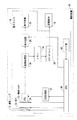
図2は、本実施形態の撮影装置10を用いて撮影を行う場合の動作を示す流れ図である。以下、図2に示すステップ番号に従って、撮影の動作を説明する。
[ステップ1] 電子カメラ14の電源ボタン(図示せず)がオンされると、電源オン処理が行われる。
【0017】
[ステップ2] CPU38は、絞り20により、撮影レンズ12の絞りを開放する。このとき、レリーズ釦40は押されていない状態であり、レリーズ釦40は待機モードに設定されている。
【0018】
[ステップ3] CPU38の指令により、CCD制御部32は、CCD24の基板電位制御端子にブルーミングを防止する電圧を供給し(請求項記載の電位差操作に対応)、CCD24を動画撮影モードに設定する。この電位差操作は、例えば、光電変換素子と半導体基板との電位差を小さくするものである。この場合、光電変換素子に所定量の電荷が蓄積された時点で、光電変換素子から半導体基板に電荷は逃がされ、隣接する光電変換素子間の電荷の漏れは防止される。なお、動画撮影モードは、請求項記載の動画撮影に適したモードに対応している。
【0019】
[ステップ4] CCD24は、被写体(図示せず)から撮影レンズ12を介して受ける光エネルギーを、電荷として蓄積する。画像処理部26は、CCD24が蓄積する電荷を、所定の間隔(電荷蓄積時間)で(連続的に)電気信号として読み出し、デジタルデータに変換する。画像処理部26は、デジタルデータにカラープロセス処理を施し、画像データとして表示回路28及びメモリ34に出力する。表示回路28は、画像データにイメージ化処理を施し、出力する。表示装置30は、表示回路28から連続的に出力される画像データを動画表示する。
【0020】
なお、画像処理部26がCCD24から電荷を読み出す時間間隔(電荷蓄積時間)は、CPU38及びCCD制御部32により制御される。
[ステップ5] CPU38は、被写体と撮影レンズ12との距離、被写体の明るさに応じて、撮影時の機械シャッタ22のシャッタ速度及び撮影レンズ12の絞り(F値)を設定する(AE:Auto Exposure)。
【0021】
[ステップ6] CPU38は、被写体と撮影レンズ12との距離に応じて、撮影レンズ12の位置、すなわち、撮影レンズ12とCCD24との距離を調節する(AF:Auto Focus)。
[ステップ7] ユーザがレリーズ釦40を半押しした場合、レリーズ釦40は、撮影準備モードに切り替わるとともに、CPU38及びCCD制御部32を介して撮影準備を指令し、ステップ8に進む。ここで、撮影準備は、ステップ8〜ステップ10に示す処理である。レリーズ釦40が押されない場合、ステップ15へ進む。
【0022】
[ステップ8] CPU38は、ステップ5で設定されたF値で、絞り20により、撮影レンズ12の絞りを絞り込む。すなわち、被写体から撮影レンズ12を介してCCD24に入射する光量は、絞り20により物理的に調節、固定される。
[ステップ9] CPU38は、撮影レンズ12の位置、及び撮影時の機械シャッタ22のシャッタ速度を固定する。
【0023】
[ステップ10] CPU38の指令により、CCD制御部32は、CCD24の基板電位制御端子に供給する電圧を切り替え、CCD24を静止画撮影モードに設定する。この電圧の切り替えは、例えば、光電変換素子と半導体基板との電位差を大きくするものである。この場合、光電変換素子が蓄積できる電荷量は大きくなるので、ダイナミックレンジは大きくなる。なお、静止画撮影モードは、請求項記載の静止画撮影に適したモードに対応している。
【0024】
[ステップ11] レリーズ釦40が半押しされたままである場合、ステップ12へ進み、ユーザがレリーズ釦40を離した場合、ステップ2へ戻る。
[ステップ12] ユーザがレリーズ釦40を全押しした場合、レリーズ釦40はCPU38を介して撮影開始を指令し、ステップ13へ進む。レリーズ釦40が半押しされたままである場合、ステップ11へ戻る。
【0025】
[ステップ13] CPU38は、表示回路28及び表示装置30に、被写体の画像の表示を動画表示から静止画表示に切り替えさせる。
[ステップ14] CPU38は、ステップ9で固定されたシャッタ速度で、機械シャッタ22を動作させる。機械シャッタ22が開いている間、CCD24に電荷が蓄積される。画像処理部26は、この電荷を電気信号として読み出す。画像処理部26は、読み出した電気信号をデジタルデータに変換してから、カラープロセス処理を施し、画像データとしてメモリ34に出力する。メモリ34に取り込まれた画像データは、メモリインターフェース36を介して、記録媒体16に記録される(撮影終了)。そして、ステップ2に戻る。
【0026】
[ステップ15] 電源ボタンがオンのままである場合、ステップ5に戻り、電源ボタンがオフにされたら、ステップ16へ進む。
[ステップ16] 電源をオフする処理が施される。
《従来の電子カメラとの相違点、本実施形態の効果》
従来の動作機構では、レリーズ釦が全押しされてから、撮像素子を静止画撮影モードに切り替える動作(本実施形態のステップ10に相応)を行い、撮影を開始していた。通常、CCD等の撮像素子のモード変更には時間がかかるため、従来の動作機構では、レリーズタイムラグの短縮には限界があった。
【0027】
そこで、本実施形態では、撮影の動作機構を以下のようにした。
まず、レリーズ釦40が待機モードである場合、CPU38及びCCD制御部32は、CCD24を動画撮影モードに設定する。レリーズ釦40は、待機モードのときに半押しされることで、撮影準備モードに切り替わるとともに撮影準備を指令する。CPU38及びCCD制御部32は、レリーズ釦40が撮影準備モードのときに、CCD24を静止画撮影モードに設定する。そして、レリーズ釦40は、撮影準備モードのときに全押しされることで、撮影モードに切り替わるとともに撮影開始を指令する。
【0028】
従来との違いは、ステップ7でレリーズ釦40が半押しされた後、撮影レンズ12の絞りを調節してから、CCD24を静止画撮影モードに切り替えたことである。従って、ステップ12でユーザがレリーズ釦40を全押しした後、CCD24のモードを変更することなく撮影を開始できる。この結果、従来の電子カメラより、レリーズタイムラグを短くできる。
【0029】
また、ステップ12でレリーズ釦40が全押しされるまでは、表示装置30は被写体の画像を動画で表示する。このため、ユーザは、レリーズ釦40を全押しするまで、表示装置30に動画で表示される被写体の画像に基づいて、撮影の構図を選択できる。
さらに、ステップ8で、被写体から撮影レンズ12を介してCCD24に入射する光量を、絞り20により物理的に小さくした後で、CCD24を静止画撮影モードに切り替えている。すなわち、CCD24が静止画撮影モードで動画撮影を行う間(ステップ10〜ステップ12)、CCD24が受ける光量は小さい。従って、CCD24が静止画撮影モードで動画撮影を行う間、ブルーミングの発生を抑制できる。
【0030】
《本実施形態の補足事項》
なお、上述した実施形態では、撮像素子としてCCD24を用いた例を述べた。本発明はかかる実施形態に限定されるものではない。撮像素子としてCMOS等を用いてもよい。
上述した実施形態では、電子カメラ14と、撮影レンズ12と、記録媒体16とが別々に形成されている例を述べた。本発明はかかる実施形態に限定されるものではない。電子カメラ14が撮影レンズ12または記録媒体16を有していてもよい。
【0031】
【発明の効果】
本発明の電子カメラでは、撮影モード制御部は、レリーズ部が撮影準備モードのときに、撮像部を静止画撮影に適したモードに設定する。このため、ユーザが撮影開始のためにレリーズ部を操作したときには、撮像部は既に静止画撮影に適したモードに設定されている。従って、撮像部が撮影を開始する直前に、撮像部のモードを切り替える必要はない。この結果、従来の電子カメラよりレリーズタイムラグを短くできる。
【図面の簡単な説明】
【図1】本実施形態の撮影装置及び本発明の電子カメラを示すブロック図である。
【図2】本実施形態の撮影装置を用いて撮影を行う場合の動作を示す流れ図である。
【符号の説明】
10 撮影装置
12 撮影レンズ
14 電子カメラ
16 記録媒体
20 絞り
22 機械シャッタ
24 CCD
26 画像処理部
28 表示回路
30 表示装置
32 CCD制御部
34 メモリ
36 メモリインターフェース
38 CPU
40 レリーズ釦[0001]
BACKGROUND OF THE INVENTION
The present invention relates to an electronic camera that captures an image of a subject, generates image data, and records the generated image data on a recording medium. The present invention also relates to an electronic camera having a function of displaying a subject as a moving image.
[0002]
[Prior art]
2. Description of the Related Art Conventionally, there has been known an electronic camera that converts light from a subject into an electric signal by an image pickup device such as a CCD (Charge Coupled Device), converts the electric signal into digital data, and records it on a recording medium such as a flash memory. Yes. Usually, an electronic camera has a color LCD (Liquid Crystal Display) on the back side. On the color LCD, the subject is displayed as a moving image before shooting as follows.
[0003]
First, the image sensor accumulates light energy received from a subject as electric charges. The accumulated charge is read out as an electrical signal at a predetermined interval. The read electrical signal is subjected to A / D conversion processing, color process processing, and the like, and is taken into a working memory such as a DRAM as image data. At the same time, the image data is also output to the display unit and subjected to image processing by a video encoder. A color LCD creates an image of a subject from image data that has been imaged and displays it as a moving image. The color LCD is used as a finder for determining the composition of shooting.
[0004]
Note that the imaging element is configured by forming a large number of photoelectric conversion elements and charge transfer electrodes on a semiconductor substrate. As such an image pickup device, one that enables switching between a moving image shooting mode and a still image shooting mode is known. In this moving image photographing mode, blooming (leakage of charge from adjacent photoelectric conversion elements or from the photoelectric conversion elements to the charge transfer electrodes) is reduced by adjusting the potential difference in the image pickup element. In the still image shooting mode, the occurrence of blooming is not suppressed. Therefore, in general, the still image shooting mode is not suitable for moving image shooting.
[0005]
[Problems to be solved by the invention]
Conventionally, in an electronic camera, it has been desired to shorten the release time lag (the time from when the release button is fully pressed until the shutter actually operates) as much as possible. This is because, for example, when shooting a moving subject, the shorter the release time lag, the easier it is for the photographer to take the timing to fully press the release button, and it becomes easier to continuously and lightly shoot. On the other hand, if the release time lag is long, it may cause a chance to miss a photo opportunity or stress the photographer.
[0006]
Therefore, an object of the present invention is to shorten the release time lag in an electronic camera having a function of displaying a subject as a moving image.
[0007]
[Means for Solving the Problems]
An electronic camera according to a first aspect includes an imaging unit, a display unit, a release unit, and a shooting mode control unit.
[0008]
The imaging unit converts light received from the subject through the lens into an electrical signal, and generates image data.
The display unit displays the image data generated by the imaging unit.
The release unit is set to any one of the standby mode, the shooting preparation mode, and the shooting preparation mode. The release unit receives a user operation in the standby mode, thereby switching to the shooting preparation mode and instructing the imaging unit to prepare for shooting. The release unit receives a user operation in the shooting preparation mode, thereby switching to the shooting mode and instructing the imaging unit to start shooting.
[0009]
The shooting mode control unit sets the imaging unit to a mode suitable for moving image shooting when the release unit is in the standby mode. When the release unit is switched to the shooting preparation mode, the shooting mode control unit sets the imaging unit to a mode suitable for still image shooting before the release unit is switched to the shooting mode.
According to another aspect of the electronic camera of the present invention, the release unit has a release button. The release button switches the release unit to the shooting preparation mode when half-pressed, switches the release unit to the shooting mode when fully pressed, and switches the release unit to the standby mode after releasing the press.
[0010]
According to another aspect of the electronic camera of the present invention, the imaging unit includes an imaging device having a plurality of photoelectric conversion elements and a plurality of charge transfer electrodes. In a mode suitable for moving image shooting, blooming is prevented by a potential difference operation in the image sensor. This potential difference operation is not performed in a mode suitable for still image shooting.
In the electronic camera according to the fourth aspect, the image of the subject is displayed as a moving image on the display unit until the release unit is switched to the shooting mode.
[0011]
In the electronic camera according to claim 5, when the release unit is switched to the shooting preparation mode, the imaging mode control unit sets the imaging unit to a still image shooting after adjusting the aperture of the lens according to the amount of light received from the subject by the imaging unit. Set to a suitable mode.
[0012]
DETAILED DESCRIPTION OF THE INVENTION
Embodiments according to
[0013]
<< Configuration of this embodiment >>
FIG. 1 is a block diagram illustrating the configuration of the photographing apparatus according to the present embodiment. The photographing
[0014]
The
<Correspondence with Claims>
The correspondence between the claims and the present invention will be described below. Note that the correspondence relationship here shows one interpretation for reference, and does not limit the present invention.
[0015]
The imaging unit described in claims corresponds to the diaphragm 20, the mechanical shutter 22, the
[0016]
<Explanation of shooting operation>
FIG. 2 is a flowchart showing an operation when photographing is performed using the photographing
[Step 1] When a power button (not shown) of the
[0017]
[Step 2] The
[0018]
[Step 3] In response to a command from the
[0019]
[Step 4] The
[0020]
The time interval (charge accumulation time) at which the
[Step 5] The
[0021]
[Step 6] The
[Step 7] When the user half-presses the
[0022]
[Step 8] The
[Step 9] The
[0023]
[Step 10] In response to a command from the
[0024]
[Step 11] If the
[Step 12] When the user fully presses the
[0025]
[Step 13] The
[Step 14] The
[0026]
[Step 15] If the power button remains on, the process returns to step 5, and if the power button is turned off, the process proceeds to step 16.
[Step 16] Processing to turn off the power is performed.
<< Differences from conventional electronic cameras, effects of this embodiment >>
In the conventional operation mechanism, after the release button is fully pressed, an operation of switching the image sensor to the still image shooting mode (corresponding to step 10 of the present embodiment) is performed to start shooting. Usually, since it takes time to change the mode of an image sensor such as a CCD, the conventional operation mechanism has a limit in shortening the release time lag.
[0027]
Therefore, in this embodiment, the shooting operation mechanism is as follows.
First, when the
[0028]
The difference from the prior art is that after the
[0029]
Further, until the
Further, in
[0030]
<< Additional items of this embodiment >>
In the above-described embodiment, the example in which the
In the above-described embodiment, the example in which the
[0031]
【The invention's effect】
In the electronic camera of the present invention, the shooting mode control unit sets the imaging unit to a mode suitable for still image shooting when the release unit is in the shooting preparation mode. For this reason, when the user operates the release unit to start shooting, the imaging unit is already set to a mode suitable for still image shooting. Therefore, it is not necessary to switch the mode of the imaging unit immediately before the imaging unit starts shooting. As a result, the release time lag can be shortened compared with the conventional electronic camera.
[Brief description of the drawings]
FIG. 1 is a block diagram showing a photographing apparatus of an embodiment and an electronic camera of the invention.
FIG. 2 is a flowchart showing an operation when photographing is performed using the photographing apparatus of the present embodiment.
[Explanation of symbols]
DESCRIPTION OF
26
40 Release button
Claims (5)
前記画像データを表示する表示部と、
待機モードと撮影準備モードと撮影モードとを有し、前記待機モードのときにユーザの操作を受けることで、前記撮影準備モードに切り替わるとともに前記撮像部に撮影準備を指令し、前記撮影準備モードのときにユーザの操作を受けることで、前記撮影モードに切り替わるとともに前記撮像部に撮影開始を指令するレリーズ部と、
前記レリーズ部が前記待機モードである場合、前記撮像部を動画撮影に適したモードに設定し、前記レリーズ部が前記撮影準備モードに切り替わった場合、前記レリーズ部が前記撮影モードに切り替わる前に、前記撮像部を静止画撮影に適したモードに設定する撮影モード制御部と
を備えていることを特徴とする電子カメラ。An imaging unit that converts light received from a subject via a lens into an electrical signal and generates image data;
A display unit for displaying the image data;
It has a standby mode, a shooting preparation mode, and a shooting mode. By receiving a user operation in the standby mode, it switches to the shooting preparation mode and instructs the imaging unit to prepare for shooting. A release unit that switches to the shooting mode and instructs the imaging unit to start shooting,
When the release unit is in the standby mode, the imaging unit is set to a mode suitable for moving image shooting, and when the release unit is switched to the shooting preparation mode, before the release unit is switched to the shooting mode, An electronic camera comprising: a shooting mode control unit that sets the imaging unit to a mode suitable for still image shooting.
半押しされたときに前記レリーズ部を前記撮影準備モードに切り替え、全押しされたときに前記レリーズ部を前記撮影モードに切り替え、押圧の解除以後に前記レリーズ部を前記待機モードに切り替えるレリーズ釦を、前記レリーズ部は備えていることを特徴とする電子カメラ。The electronic camera according to claim 1.
A release button that switches the release unit to the shooting preparation mode when half-pressed, switches the release unit to the shooting mode when fully pressed, and switches the release unit to the standby mode after release of the press. An electronic camera comprising the release unit.
前記撮像部は、複数の光電変換素子及び複数の電荷転送電極を有する撮像素子を備え、
前記動画撮影に適したモードは、前記撮像素子内の電位差操作によりブルーミングを防止するモードであり、
前記静止画撮影に適したモードは、前記電位差操作が行われないモードであることを特徴とする電子カメラ。The electronic camera according to claim 1 or 2,
The imaging unit includes an imaging element having a plurality of photoelectric conversion elements and a plurality of charge transfer electrodes,
The mode suitable for moving image shooting is a mode for preventing blooming by a potential difference operation in the image sensor,
The mode suitable for still image shooting is a mode in which the potential difference operation is not performed.
前記レリーズ部が前記撮影モードに切り替わるまでは、前記表示部に前記被写体の画像を動画で表示させる手段を備えていることを特徴とする電子カメラ。The electronic camera according to any one of claims 1 to 3,
An electronic camera comprising: means for displaying the subject image as a moving image on the display unit until the release unit is switched to the shooting mode.
前記レリーズ部が前記撮影準備モードに切り替わった場合、前記撮像部が前記被写体から受ける光量に応じて前記レンズの絞りを調節してから、前記撮影モード制御部は前記撮像部を前記静止画撮影に適したモードに設定することを特徴とする電子カメラ。The electronic camera according to claim 4.
When the release unit is switched to the shooting preparation mode, the imaging mode control unit adjusts the imaging unit to the still image shooting after adjusting the aperture of the lens according to the amount of light received from the subject by the imaging unit. An electronic camera that is set to a suitable mode.
Priority Applications (6)
| Application Number | Priority Date | Filing Date | Title |
|---|---|---|---|
| JP2002154006A JP3757906B2 (en) | 2002-05-28 | 2002-05-28 | Electronic camera |
| CNB038121328A CN100380927C (en) | 2002-05-28 | 2003-05-27 | Electronic camera |
| US10/515,379 US7489343B2 (en) | 2002-05-28 | 2003-05-27 | Electronic camera |
| EP03733094A EP1526718B1 (en) | 2002-05-28 | 2003-05-27 | Electronic camera |
| DE60333015T DE60333015D1 (en) | 2002-05-28 | 2003-05-27 | ELECTRONIC CAMERA |
| PCT/JP2003/006603 WO2003101092A1 (en) | 2002-05-28 | 2003-05-27 | Electronic camera |
Applications Claiming Priority (1)
| Application Number | Priority Date | Filing Date | Title |
|---|---|---|---|
| JP2002154006A JP3757906B2 (en) | 2002-05-28 | 2002-05-28 | Electronic camera |
Publications (2)
| Publication Number | Publication Date |
|---|---|
| JP2003348433A JP2003348433A (en) | 2003-12-05 |
| JP3757906B2 true JP3757906B2 (en) | 2006-03-22 |
Family
ID=29561339
Family Applications (1)
| Application Number | Title | Priority Date | Filing Date |
|---|---|---|---|
| JP2002154006A Expired - Fee Related JP3757906B2 (en) | 2002-05-28 | 2002-05-28 | Electronic camera |
Country Status (6)
| Country | Link |
|---|---|
| US (1) | US7489343B2 (en) |
| EP (1) | EP1526718B1 (en) |
| JP (1) | JP3757906B2 (en) |
| CN (1) | CN100380927C (en) |
| DE (1) | DE60333015D1 (en) |
| WO (1) | WO2003101092A1 (en) |
Families Citing this family (12)
| Publication number | Priority date | Publication date | Assignee | Title |
|---|---|---|---|---|
| JP4381053B2 (en) * | 2003-08-07 | 2009-12-09 | 三洋電機株式会社 | Imaging device |
| JP4054918B2 (en) * | 2004-03-26 | 2008-03-05 | カシオ計算機株式会社 | Imaging apparatus, photographing control method, and photographing control program |
| JP2007110178A (en) * | 2005-10-11 | 2007-04-26 | Sanyo Electric Co Ltd | Camera capable of photographing still picture and animation |
| EP2282520A3 (en) * | 2005-12-06 | 2011-09-21 | Panasonic Corporation | Digital camera |
| US7783191B2 (en) | 2006-08-10 | 2010-08-24 | Hoya Corporation | Digital camera |
| JP5086731B2 (en) * | 2006-08-10 | 2012-11-28 | ペンタックスリコーイメージング株式会社 | camera |
| US20080266438A1 (en) * | 2007-04-30 | 2008-10-30 | Henrik Eliasson | Digital camera and method of operation |
| JP2009118215A (en) * | 2007-11-07 | 2009-05-28 | Canon Inc | Imaging apparatus |
| KR101239952B1 (en) * | 2008-03-03 | 2013-03-06 | 삼성전자주식회사 | Image forming apparatus and control method thereof |
| JP5171398B2 (en) * | 2008-06-02 | 2013-03-27 | 三洋電機株式会社 | Imaging device |
| JP5159589B2 (en) * | 2008-12-08 | 2013-03-06 | キヤノン株式会社 | Imaging device |
| JP7101044B2 (en) * | 2018-05-24 | 2022-07-14 | 三井・ケマーズ フロロプロダクツ株式会社 | Fluororesin paint composition |
Family Cites Families (12)
| Publication number | Priority date | Publication date | Assignee | Title |
|---|---|---|---|---|
| JPS58117776A (en) * | 1981-12-30 | 1983-07-13 | Sony Corp | Solid-state image pickup device |
| US5185669A (en) * | 1990-10-01 | 1993-02-09 | Sony Corporation | Still video camera with white balance and image pickup lens adjustment |
| US5703638A (en) * | 1991-09-25 | 1997-12-30 | Canon Kabushiki Kaisha | Image pickup apparatus for moving image photographing or for still image photographing |
| JP3847811B2 (en) | 1995-06-30 | 2006-11-22 | キヤノン株式会社 | Imaging device |
| JPH10136244A (en) * | 1996-11-01 | 1998-05-22 | Olympus Optical Co Ltd | Electronic image pickup device |
| JPH11212177A (en) * | 1998-01-22 | 1999-08-06 | Ricoh Co Ltd | Camera |
| GB9809679D0 (en) * | 1998-05-06 | 1998-07-01 | Xerox Corp | Portable text capturing method and device therefor |
| JP3820497B2 (en) * | 1999-01-25 | 2006-09-13 | 富士写真フイルム株式会社 | Imaging apparatus and correction processing method for automatic exposure control |
| JP3596860B2 (en) | 1999-08-27 | 2004-12-02 | キヤノン株式会社 | Imaging device |
| JP3877474B2 (en) * | 1999-08-03 | 2007-02-07 | 三洋電機株式会社 | Electronic camera |
| JP3679693B2 (en) * | 2000-07-31 | 2005-08-03 | 三洋電機株式会社 | Auto focus camera |
| JP4020591B2 (en) | 2001-03-02 | 2007-12-12 | 富士フイルム株式会社 | Digital camera and voltage supply circuit |
-
2002
- 2002-05-28 JP JP2002154006A patent/JP3757906B2/en not_active Expired - Fee Related
-
2003
- 2003-05-27 EP EP03733094A patent/EP1526718B1/en not_active Expired - Fee Related
- 2003-05-27 CN CNB038121328A patent/CN100380927C/en not_active Expired - Fee Related
- 2003-05-27 WO PCT/JP2003/006603 patent/WO2003101092A1/en active Application Filing
- 2003-05-27 US US10/515,379 patent/US7489343B2/en not_active Expired - Fee Related
- 2003-05-27 DE DE60333015T patent/DE60333015D1/en not_active Expired - Lifetime
Also Published As
| Publication number | Publication date |
|---|---|
| EP1526718A4 (en) | 2007-04-04 |
| EP1526718A1 (en) | 2005-04-27 |
| EP1526718B1 (en) | 2010-06-16 |
| CN100380927C (en) | 2008-04-09 |
| JP2003348433A (en) | 2003-12-05 |
| US20050243179A1 (en) | 2005-11-03 |
| US7489343B2 (en) | 2009-02-10 |
| WO2003101092A1 (en) | 2003-12-04 |
| CN1656795A (en) | 2005-08-17 |
| DE60333015D1 (en) | 2010-07-29 |
Similar Documents
| Publication | Publication Date | Title |
|---|---|---|
| JP4127491B2 (en) | Camera with auto focus function | |
| US7440022B2 (en) | Image sensing apparatus with electronic shutter function and mechanical shutter function, and image sensing method | |
| US7729609B2 (en) | Image sensing apparatus and control method | |
| JP3757906B2 (en) | Electronic camera | |
| JP2003018438A (en) | Imaging apparatus | |
| JP4809537B2 (en) | Imaging control apparatus and imaging control method | |
| JP2006243372A (en) | Camera | |
| JP2011044872A (en) | Imaging apparatus, method of adjusting exposure, and program | |
| JP2003018437A (en) | Imaging apparatus | |
| JP3955493B2 (en) | Digital camera and automatic focusing method thereof | |
| JP2006293082A (en) | Imaging apparatus | |
| JP2011087050A (en) | Digital camera | |
| JP6244824B2 (en) | Imaging apparatus and imaging method | |
| JPH09181954A (en) | Electronic still camera and method for focus-controlling the same | |
| JP4086337B2 (en) | Imaging device | |
| JPH11234573A (en) | Photographing method for electronic camera | |
| JP4468601B2 (en) | Electronic camera | |
| JP2004287183A (en) | Digital camera | |
| JP2005354710A (en) | Image pickup device | |
| JP2004023452A (en) | Electronic camera | |
| JP2005017673A (en) | Method for searching for focusing position of focus lens, and imaging apparatus | |
| JP2007316471A (en) | Imaging apparatus and program therefore | |
| JP2008118263A (en) | Photography apparatus and heat generation suppressing method | |
| JP2005252800A (en) | Digital camera | |
| US20020140840A1 (en) | Camera for film photography and electronic photography |
Legal Events
| Date | Code | Title | Description |
|---|---|---|---|
| A621 | Written request for application examination |
Free format text: JAPANESE INTERMEDIATE CODE: A621 Effective date: 20050425 |
|
| TRDD | Decision of grant or rejection written | ||
| A01 | Written decision to grant a patent or to grant a registration (utility model) |
Free format text: JAPANESE INTERMEDIATE CODE: A01 Effective date: 20051206 |
|
| A61 | First payment of annual fees (during grant procedure) |
Free format text: JAPANESE INTERMEDIATE CODE: A61 Effective date: 20051219 |
|
| R150 | Certificate of patent or registration of utility model |
Ref document number: 3757906 Country of ref document: JP Free format text: JAPANESE INTERMEDIATE CODE: R150 Free format text: JAPANESE INTERMEDIATE CODE: R150 |
|
| FPAY | Renewal fee payment (event date is renewal date of database) |
Free format text: PAYMENT UNTIL: 20120113 Year of fee payment: 6 |
|
| FPAY | Renewal fee payment (event date is renewal date of database) |
Free format text: PAYMENT UNTIL: 20120113 Year of fee payment: 6 |
|
| FPAY | Renewal fee payment (event date is renewal date of database) |
Free format text: PAYMENT UNTIL: 20150113 Year of fee payment: 9 |
|
| S531 | Written request for registration of change of domicile |
Free format text: JAPANESE INTERMEDIATE CODE: R313531 |
|
| FPAY | Renewal fee payment (event date is renewal date of database) |
Free format text: PAYMENT UNTIL: 20150113 Year of fee payment: 9 |
|
| R350 | Written notification of registration of transfer |
Free format text: JAPANESE INTERMEDIATE CODE: R350 |
|
| FPAY | Renewal fee payment (event date is renewal date of database) |
Free format text: PAYMENT UNTIL: 20150113 Year of fee payment: 9 |
|
| R250 | Receipt of annual fees |
Free format text: JAPANESE INTERMEDIATE CODE: R250 |
|
| R250 | Receipt of annual fees |
Free format text: JAPANESE INTERMEDIATE CODE: R250 |
|
| R250 | Receipt of annual fees |
Free format text: JAPANESE INTERMEDIATE CODE: R250 |
|
| R250 | Receipt of annual fees |
Free format text: JAPANESE INTERMEDIATE CODE: R250 |
|
| R250 | Receipt of annual fees |
Free format text: JAPANESE INTERMEDIATE CODE: R250 |
|
| LAPS | Cancellation because of no payment of annual fees |