JP2004287183A - Digital camera - Google Patents
Digital camera Download PDFInfo
- Publication number
- JP2004287183A JP2004287183A JP2003080403A JP2003080403A JP2004287183A JP 2004287183 A JP2004287183 A JP 2004287183A JP 2003080403 A JP2003080403 A JP 2003080403A JP 2003080403 A JP2003080403 A JP 2003080403A JP 2004287183 A JP2004287183 A JP 2004287183A
- Authority
- JP
- Japan
- Prior art keywords
- temperature
- lens
- photographing lens
- image
- focus
- Prior art date
- Legal status (The legal status is an assumption and is not a legal conclusion. Google has not performed a legal analysis and makes no representation as to the accuracy of the status listed.)
- Pending
Links
Images


Landscapes
- Studio Devices (AREA)
- Focusing (AREA)
- Lens Barrels (AREA)
Abstract
Description
【0001】
【発明の属する技術分野】
本発明は、デジタルカメラに関し、更に詳しくは温度変化があってもスルー画をピントよく表示できるデジタルカメラに関するものである。
【0002】
【従来の技術】
CCDやCMOSイメージセンサ等の固体撮像素子を用いて撮影画像の画像データをデジタルデータとしてメモリカードに記録するデジタルカメラが普及してきている。デジタルカメラの多くには、フレーミングの際に、固体撮像素子が撮像した画像をリアルタイムで再生し、これを液晶パネルにスルー画として表示する電子ビューファインダが設けられている。
【0003】
デジタルカメラの比較的高価格帯に属する機種では、コンティニュアスAFを搭載しており、電子ビューファインダの表示画面でもリアルタイムにピント合わせを行って常にシャープなスルー画を表示しているが、比較的低価格帯に属する機種では、撮影レンズを固定焦点式として、コンティニュアスAFを搭載していない。
【0004】
また、比較的低価格帯に属するデジタルカメラでは、よりローコスト化,小型軽量化を図るため、撮影レンズがガラスレンズからプラスチックレンズになってきている。ところが、プラスチックレンズは、温度変化による屈折率の変化がガラスレンズと比べて約100倍と非常に大きいため、温度変化によって焦点距離が大きく変動するという欠点がある。
【0005】
このため、例えば特許文献1記載の固定焦点カメラでは、固定焦点式の撮影レンズまたは固体撮像素子を撮影光軸方向に移動自在に設けるとともに、レンズ鏡胴の外周面に温度センサを取り付け、レンズ鏡胴の温度を示す情報をCPUに出力し、CPUが温度情報に基づいてCCD又は撮影レンズを移動することによりCCDと撮影レンズとの距離を変更し、レンズ鏡胴の熱膨張,熱収縮によるピントずれを補正している。
【0006】
【特許文献1】
特開平8−114736号公報
【0007】
【発明が解決しようとする課題】
ところで、中間的な価格帯のデジタルカメラでは、オートフォーカス機構を搭載しており、実際の撮影時にはピント合わせを行うが、スルー画表示では撮影レンズをパンフォーカスにしてピント合わせを行わないものが多い。ところが、上述したように撮影レンズをプラスチックレンズとすると、温度変化によって撮影レンズのピントずれが発生しやすいため、電子ビューファインダに表示されたスルー画がピンぼけになる場合がある。なお、上記特許文献1には、スルー画についての記載はない。
【0008】
本発明は、温度変化があってもスルー画をピントよく表示できるデジタルカメラを提供することを目的とする。
【0009】
【課題を解決するための手段】
上記目的を達成するために、本発明のデジタルカメラは、撮影レンズによって結像される被写体像を光電変換して撮影画像を得る撮像手段と、前記撮影レンズをパンフォーカスにして撮像手段によって取り込まれるフレームをリアルタイムで再生してスルー画として表示する電子ビューファインダとを備えたデジタルカメラにおいて、前記撮影レンズの温度を測る温度測定手段と、前記撮影レンズの温度に対する撮影レンズのピント修正量を表す温度ルックアップテーブルと、この温度ルックアップテーブルを参照して撮影レンズのピント位置を修正する制御手段とを設けたものである。
【0010】
また、撮影レンズによって結像される被写体像を光電変換して撮影画像を得る撮像手段と、この撮像手段によって取り込まれるフレームをリアルタイムで再生してスルー画として表示する電子ビューファインダと、被写体との距離を測って撮影レンズのピント合わせを行うオートフォーカス手段とを備えたデジタルカメラにおいて、前記撮影レンズの温度を測る温度測定手段と、前記オートフォーカス手段を電源投入に伴って作動させる初期合焦手段と、前記電源投入時の撮影レンズの温度とその後に変化した撮影レンズの温度との差に応じて撮影レンズのピント修正量を表す温度差ルックアップテーブルと、この温度差ルックアップテーブルを参照して撮影レンズのピント位置を修正する制御手段とを設けたものである。
【0011】
また、撮影レンズによって結像される被写体像を光電変換して撮影画像を得る撮像手段と、この撮像手段によって取り込まれるフレームをリアルタイムで再生してスルー画として表示する電子ビューファインダと、シャッタボタンの半押し又は全押しにより撮影レンズのピント合わせを自動的に行うオートフォーカス手段とを備えたデジタルカメラにおいて、前記撮影レンズの温度を測る温度測定手段と、前記オートフォーカス手段による合焦時の撮影レンズの温度とその後に変化した撮影レンズの温度との差に応じて撮影レンズのピント修正量を表す温度差ルックアップテーブルと、この温度差ルックアップテーブルを参照して撮影レンズのピント位置を修正する制御手段とを設けたものである。
【0012】
また、撮影レンズによって結像される被写体像を光電変換して撮影画像を得る撮像手段と、この撮像手段によって取り込まれるフレームをリアルタイムで再生してスルー画として表示する電子ビューファインダと、シャッタボタンの半押し又は全押しにより撮影レンズのピント合わせを自動的に行うオートフォーカス手段とを備えたデジタルカメラにおいて、前記撮影レンズの温度を測る温度測定手段と、前記オートフォーカス手段による合焦時の撮影レンズの温度とその後に変化した撮影レンズの温度との差に応じて撮影レンズのピント修正量を表す温度差ルックアップテーブルと、シャッタボタンの半押しを継続する間に、この温度差ルックアップテーブルを参照して撮影レンズのピント位置を修正する制御手段とを設けたものである。
【0013】
また、前記オートフォーカス手段による撮影レンズの合焦が不成功であった場合に、前記制御手段は、撮影レンズをパンフォーカスにするとともに、撮影レンズの温度に対する撮影レンズのピント修正量を表す温度ルックアップテーブルを参照して撮影レンズのピント位置を修正するものである。
【0014】
また、撮影レンズによって結像される被写体像を光電変換して撮影画像を得る撮像手段と、この撮像手段によって取り込まれるフレームをリアルタイムで再生してスルー画として表示する電子ビューファインダと、シャッタボタンの半押し又は全押しにより撮影レンズのピント合わせを自動的に行うオートフォーカス手段とを備えたデジタルカメラにおいて、前記撮影レンズの温度を測る温度測定手段と、前記撮影レンズの温度に対する撮影レンズのピント修正量を表す温度ルックアップテーブルと、前記温度測定手段から出力された撮影レンズの温度が温度ルックアップテーブルを参照して撮影レンズのピント修正を行うべき温度である場合に、前記撮影レンズをパンフォーカスにするとともに、前記温度ルックアップテーブルを参照して撮影レンズのピント位置を修正する制御手段とを設けたものである。
【0015】
また、撮影レンズによって結像される被写体像を光電変換して撮影画像を得る撮像手段と、この撮像手段によって取り込まれるフレームをリアルタイムで再生してスルー画として表示する電子ビューファインダと、シャッタボタンの半押し又は全押しにより撮影レンズのピント合わせを自動的に行うオートフォーカス手段とを備えたデジタルカメラにおいて、前記撮影レンズの温度を測る温度測定手段と、前記オートフォーカス手段による合焦時の撮影レンズの温度とその後に変化した撮影レンズの温度との差に応じて撮影レンズのピント修正量を表す温度差ルックアップテーブルと、前記撮影レンズの温度に対する撮影レンズのピント修正量を表す温度ルックアップテーブルと、前記合焦時の撮影レンズの温度とその後に変化した撮影レンズの温度との差が予め決められた限界値を超えた場合に、前記撮影レンズをパンフォーカスにするとともに、前記温度ルックアップテーブルを参照して撮影レンズのピント位置を修正する制御手段とを設けたものである。
【0016】
また、撮影レンズによって結像される被写体像を光電変換して撮影画像を得る撮像手段と、この撮像手段によって取り込まれるフレームをリアルタイムで再生してスルー画として表示する電子ビューファインダと、シャッタボタンの半押し又は全押しにより撮影レンズのピント合わせを自動的に行うオートフォーカス手段とを備えたデジタルカメラにおいて、前記撮影レンズの温度を測る温度測定手段と、前記オートフォーカス手段による合焦時の撮影レンズの温度とその後に変化した撮影レンズの温度との差に応じて撮影レンズのピント修正量を表す温度差ルックアップテーブルと、前記撮影レンズの温度に対する撮影レンズのピント修正量を表す温度ルックアップテーブルと、前記オートフォーカス手段による合焦時から一定時間が経過した後、前記撮影レンズをパンフォーカスにするとともに、前記温度ルックアップテーブルを参照して撮影レンズのピント位置を修正する制御手段とを設けたものである。
【0017】
【発明の実施の形態】
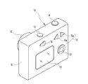
本発明の第1実施形態の外観を示す図1において、デジタルカメラ10のカメラ本体11前面には、ズームレンズが組み込まれたレンズ鏡筒12が設けられており、上面には、電源ボタン13及びシャッタボタン14が設けられている。また、カメラ本体11の背面には、ズームボタン16,4つのボタンが十字配列された汎用キー17,モード選択レバー18、液晶(LCD:Liquid Crystal Display)パネル19が設けられている。
【0018】
モード選択レバー18は、撮影を行う撮影モード、撮影画像を再生する再生モード、各種設定を行うセットアップモードなどの各種のモードを選択する。汎用キー17は、メニュー画面内に表示され各種項目を選択するカーソルの移動や、項目の選択等に使用される。液晶パネル19は、再生モードにおいては、撮影画像の再生表示に使用され、セットアップモードでは、各種設定を行うためのメニュー画面の表示に用いられるとともに、撮影モードでは、被写体確認用画像であるスルー画を表示する電子ビューファインダとして使用される。
【0019】
ズームボタン16は、拡大ボタン16a、縮小ボタン16bからなり、レンズ鏡筒12に組み込まれたズームレンズの変倍を行う。なお、実際にズームレンズの変倍を行う前に、電子ズームによる変倍を行い、フレーミングが決まった後、シャッタボタン14の全押しにより、電子ズーム倍率に応じてズームレンズの光学ズーム倍率を変更して本画像の撮影処理を実行するようにしてもよい。
【0020】
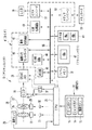
図2は、デジタルカメラ10の構成を示すブロック図である。カメラ本体11には、メモリカード23が着脱自在にセットされる。このメモリカード23には、後述する本画像の画像データが、例えば、JPG(Joint Photographic expert Group )形式の画像ファイルに変換されて記憶される。
【0021】
CPU21は、操作部22から入力される操作信号に応じてデジタルカメラ10の本体各部を制御する。レンズ鏡筒12内には、撮影レンズとしてのズームレンズ24が組み込まれている。このズームレンズ24は、レンズ26と絞り27からなる。
【0022】
前記レンズ26は、複数枚のプラスチックレンズから構成されたバリエータレンズである前群レンズと、やはり複数枚のプラスチックレンズから構成されたフォーカシング機能をもったコンペンセータレンズである後群レンズ(以下フォーカスレンズという)とからなる2群構成となっている。これにより、ズームレンズ24のレンズ26は、軽量化が図られている反面、温度変化によってプラスチックレンズが膨張,収縮してピント位置がずれるという特性を有する。このため、レンズ26の温度(より正確にはズームレンズ24近傍の温度)を測定して温度データをCPU21に出力する温度センサ25が、ズームレンズ24の近傍に設けられている。
【0023】
前記レンズ26は、ステッピングモータを含むレンズ駆動機構28によって駆動されて、光学ズーム倍率の変更と焦点調節が行われる。絞り27は、モータを含む絞り駆動機構29によって駆動されて絞り径が切り換えられる。レンズ駆動機構28及び絞り駆動機構29は、CPU21に制御されるモータドライバ31,32によって駆動される。
【0024】
スルー画の表示を行う際には、各焦点距離(各変倍位置)においてズームレンズ24がパンフォーカス状態となるように、絞り27の絞り径が変更される。
【0025】
撮影光学系の背後には、撮像素子としてCCD33が配置されている。CCD33は、周知のように、多数の受光素子をマトリックス状に配列された光電面を備えており、撮影光学系を通過し、この光電面に結像した被写体光を光電変換する。光電面の前方には、各画素に光を集光するためのマイクロレンズアレイと、各画素がそれぞれR,G,Bのいずれかに対応するように各色のフイルタが規則的に配列されたカラーフイルタアレイとが配置されている。
【0026】
CCD33は、CCDドライバ36から供給される垂直転送クロック及び水平転送クロックに同期して、画素毎に蓄積された電荷を1ラインずつシリアルな撮像信号として出力する。各画素の電荷蓄積時間(露出時間)は、CCDドライバ36から与えられる電子シャッタ駆動信号によって決められる。
【0027】
CCD33から取り込まれたアナログの撮像信号は、アナログ信号処理回路38に入力される。アナログ信号処理回路38は、相関2重サンプリング回路(CDS)と、オートゲインコントローラ(AGC)と、ADコンバータ(ADC)とからなる。前記CDSは、アナログ信号のノイズを除去し、AGCはアナログ信号のゲインを自動調節する。
【0028】
前記ADCは、アナログ信号をデジタル変換して画像データを生成する。この画像データは、各画素毎にR,G,Bの濃度値を持つCCD−RAWデータであり、このCCD−RAWデータがDSP(Digital Signal Processor) 41へ入力される。アナログ信号処理回路38にも、タイミングジェネレータ(TG)37からのタイミング信号が供給され、CCD33から電荷が取り込みまれるタイミングと同期が取られている。
【0029】
CCD33から取り込まれる画像データには、本撮影時に取り込まれメモリカード23へ記録される本画像と、フレーミングに利用されるスルー画とがある。
スルー画は、撮影モードが選択されている間、所定のフレームレート(例えば、1秒間に30コマ)で取り込まれる。また、スルー画は、表示用の画像であるため、本画像と比較して画素数が少ない。シャッタボタン14の全押しにより撮影指示がなされると、本画像が取り込まれる。CCD33から取り込まれた画像は、フレームメモリ39へ書き込まれる。
【0030】
フレームメモリ39は、DSP(Digital Signal Processor) 41が画像データに対して各種信号処理を施す際に使用する作業用メモリである。フレームメモリ39は、データバス55を介して、CPU21とDSP41の各部と接続されている。フレームメモリ39としては、例えば、一定周期のバスクロック信号に同期してデータ転送を行うSDRAM(Synchronous Dynamic Random Access Memory)が使用される。フレームメモリ39に書き込まれた画像は、DSP41によって各種の画像処理が施される。
【0031】
また、データバス55を介して、フラッシュメモリ42が接続されている。このフラッシュメモリ42には、次の表1に示すように、焦点距離Z1,Z2,Z3,・・・におけるズームレンズ24の温度と、ピント位置を補正するためにレンズ駆動機構28のステッピングモータに印加される補正パルス数との関係を表すルックアップテーブル42aが記憶されている。
【0032】
【表1】
なお、焦点距離Z1,Z2,Z3,・・・は、ズームレンズ24のズーミング範囲から、例えば10個の焦点距離を任意に選択したものである。ズームレンズ24のズーミング範囲が、例えば35ミリ換算で28ミリ〜100ミリである場合、焦点距離Z1,Z2,Z3,・・・Z10は、例えば28ミリ,30ミリ,35ミリ,38ミリ,40ミリ,50ミリ,60ミリ,70ミリ,85ミリ,100ミリである。
【0034】
表1に示すように、ルックアップテーブル42aでは、ズームレンズ24の現在の温度Tが、現状位置(焦点距離及びピント位置)での温度範囲(T3+T4)/2<T<(T4+T5)/2を満たす場合には、ピント位置の修正は行わず、例えば、初期位置のワイド端である焦点距離Z1でズームレンズ24の現在の温度Tが、基準温度であるT4(25℃)からT5(30℃)に変動した場合、+方向(ニア(near)方向)にピント位置が移動されるように5個のパルスをステッピングモータに印加する。また、例えば、焦点距離Z2でズームレンズ24の現在の温度TがT4(25℃)からT3(20℃)に変動した場合、−方向(インフ(inf.:infinity)方向)にピント位置を移動するように3個のパルスをステッピングモータに印加する。
【0035】
DSP41は、AF回路43,AE/AWB回路44,画像入力コントローラ46,画像処理回路48,圧縮処理回路49,メディアコントローラ50,ビデオエンコーダ51からなるICチップであり、アナログ信号処理回路38から入力された画像データに対して、各種の信号処理を施すとともに、スルー画のLCD19への表示や、メモリカード23へアクセスして画像ファイルの読み書きを行う。
【0036】
画像入力コントローラ46は、アナログ信号処理回路38から前記CCD−RAWデータを取り込んで、これをフレームメモリ39に書き込む。AF回路43は、シャッタボタン14の半押し又は全押しに応答して、CCD33が撮像した画像に基づいて、焦点位置を検出する。AE回路は、被写体輝度を測定し、絞り値やシャッタ速度等を決定する。AWB回路は、オートホワイトバランス回路であり、撮影時のホワイトバランスを自動調整する。
【0037】
圧縮処理回路49は、画像処理回路48によって各種の画像処理が施された本画像のデータに対して、圧縮処理を施して、画像ファイルを生成する。メディアコントローラ50は、メモリカード23へアクセスして画像ファイルの書き込みと読み込みとを行う。再生モードにおいては、メモリカード23から圧縮された画像データが読み出されて、圧縮処理回路49によって伸張処理が施された後、LCD19に出力される。
【0038】
画像処理回路48は、画像データに対して、ガンマ補正,シャープネス補正,コントラスト補正などの画質補正処理、CCD−RAWデータを輝度信号であるYデータと、青色色差信号であるCbデータ及び赤色色差信号であるCrデータとからなるYCデータに変換するYC処理を施す。
【0039】
VRAM40は、LCD19への画像出力用メモリである。スルー画は、このVRAM40に一旦書き込まれてから、ビデオエンコーダ51へ送られる。ビデオエンコーダ51は、デジタルデータをアナログのコンポジット信号に変換してLCD19に出力する。スルー画は、高速で書き換えられるので、VRAM40には、データの書き込みと読み出しとを並行してできるように、2フレーム分のエリア40a,40bが設けられている。
【0040】
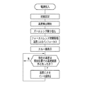
このように構成された第1実施形態の作用について、図3に示すフローチャートを参照しながら説明する。電源ボタン13を押して電源を投入した直後には、デジタルカメラ10の初期設定が行われる。この初期設定では、CPU21や周辺ICの立ち上げ等が行われる。この後、CPU21は、温度センサ25から出力される温度データの読み込みを開始する。
【0041】
続いて、ズームレンズ24が沈胴位置から繰り出され、初期位置であるワイド端(焦点距離Z1)にセットされると同時に、パンフォーカス状態となるように絞り27の絞り径がセットされる。続いて、スルー画取り込みと取り込んだスルー画の液晶パネル19への表示を開始する。
【0042】
ユーザは、自由にズームボタン16の拡大ボタン16a、縮小ボタン16bを押してズームレンズ24の変倍を行いながらフレーミングを行う。このズームレンズ24の変倍中、全ての焦点距離でパンフォーカス状態になるように、絞り27の絞り径が変更され、これに伴って低下する光量を補うために、アナログ信号処理回路38のAGCがCCD33から取り込まれたアナログ信号のゲインを自動調節する。
【0043】
CPU21は、常に温度センサ25から出力される温度データをチェックして、各焦点距離Z1,Z2,・・・における現在の温度Tを確認する。そして、ルックアップテーブル42aを参照して、現在の温度Tが現状位置での温度範囲(T3+T4)/2<T<(T4+T5)/2を満たす場合には、ピント位置の修正は不要であるから、そのままスルー画の表示を継続する。
【0044】
現在の温度Tが温度範囲(T3+T4)/2<T<(T4+T5)/2を満たさなくなった時、例えば現在の温度TがT5(30℃)に達すると、CPU21は、フラッシュメモリ42のルックアップテーブル42aを参照して、焦点距離Z1,Z2,Z3,・・・から現在の焦点距離に最も近い焦点距離を選択し、その焦点距離におけるピント位置を修正するためにレンズ駆動機構28のステッピングモータに印加するべきパルス数を読み出す。例えば焦点距離Z3では、パルス数はニア(near)方向に6個である。
【0045】
更に、現在の温度TがT6(35℃)に達したら、ステッピングモータに7個のパルス数を印加する(T4を基準として+13)。また、この後、現在の温度Tが温度範囲(T3+T4)/2<T<(T4+T5)/2に戻った場合には、インフ(inf.)方向にフォーカスレンズを移動する13個のパルスをステッピングモータに印加する。
【0046】
CPU21は、ルックアップテーブル42aから読み出したパルス数をレンズ駆動機構28のステッピングモータに印加してズームレンズ24のフォーカスレンズを移動する。これにより、ピント位置が修正され、ピントが合ったシャープなスルー画が液晶パネル19に表示される。
【0047】
撮影者は、液晶パネル19に表示されたスルー画を見ながらフレーミングを行う。フレーミングが完了してシャッタボタン14が半押しされると、測光及び測距が行われ、絞り調節やフォーカシングが行われる。このフォーカシングが行われた際には、スルー画表示におけるパンフォーカス状態は解除され、フォーカシングが行われた状態でのスルー画が液晶パネル19に表示される。さらに、シャッタボタン14が全押しされると、スルー画の表示が中断され、CCD33によって本撮影が行われる。取り込まれた本画像は、各種の画像処理が施された後、メモリカード23に記録される。本撮影が終了すると、スルー画の表示が再開される。
【0048】
次に、第2実施形態のデジタルカメラ60は、図4に示すように、フラッシュメモリ42に2つのルックアップテーブル42a,42bを格納している。ルックアップテーブル42bは、次の表2に示すように、相対的な温度差によってピント位置の修正を行うものである。例えば、スルー画のピント合わせが行われた(合焦した)時の温度がT4(25℃)であり、その後、ズームレンズ24の温度が例えば1℃上昇した時には、レンズ駆動機構28のステッピングモータに1個のパルスを印加してズームレンズ24のフォーカスレンズをニア(near)方向に移動し、ピント位置の修正を行う。
【0049】
【表2】
第2実施形態の作用について、図5のフローチャートを参照して説明する。電源投入後に行われるズームレンズ24の繰り出し動作の後、AF回路43が作動してピント合わせが行われ、続けてスルー画が表示される。AF回路43により合焦した場合には、CPU21はズームレンズ24の温度観測を続け、合焦時との温度差が1℃以上になったら、ルックアップテーブル42b(表2参照)を参照して、対応するパルス数をレンズ駆動機構28のステッピングモータに印加する。例えば、合焦時の温度がT3(20℃)であって、その後に温度が2℃降下した場合には、ピント位置がインフ(inf.)方向にずれるように2個のパルスをステッピングモータに印加する。
【0051】
被写体とズームレンズ24との距離が近い場合など、AF回路43で合焦しない場合には、パンフォーカス状態にセットするとともに、ルックアップテーブル42aを参照してズームレンズ24のピント位置を現在の温度に対応したピント位置に修正する。
【0052】
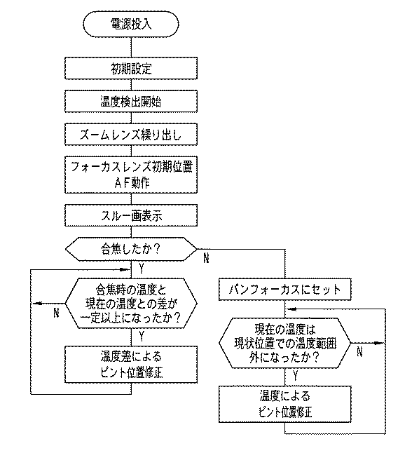
次に、第3実施形態について、図1,図4及び図6を参照して説明する。シャッタボタン14の半押し又は全押しに応答してAE処理,AF処理が行われてから、スルー画が表示される。AF処理で合焦した場合には、CPU21は、合焦時の温度と現在の温度との差が一定,本実施形態では1℃以上になるか否かを観測し、1℃以上になったらルックアップテーブル42bを参照して、フォーカスレンズを移動してピント位置を修正する。
【0053】
また、AF処理で合焦しなかった場合には、ズームレンズ24をパンフォーカスにセットしてから、ルックアップテーブル42aを参照して、現在の温度Tが現状位置(焦点距離及びピント位置)での温度範囲(例えばT4(25℃)が基準の場合(T3+T4)/2<T<(T4+T5)/2)内であれば、そのままスルー画表示が行われる。また、現在の温度Tが現状位置での温度範囲外になった場合には、ルックアップテーブル42aを参照して、現在の温度Tにおけるピント位置の修正を行う。
【0054】
次に、第4実施形態について、図1,図4及び図7を参照して説明する。シャッタボタン14の半押し又は全押しに応答してAE処理,AF処理が行われてから、スルー画が表示される。現在の温度が現状位置での温度範囲内であれば、そのままスルー画表示が行われる。また、現在の温度が現状位置での温度範囲外になった場合には、ズームレンズ24をパンフォーカスにするとともに、ルックアップテーブル42aを参照して、現在の温度におけるピント位置の修正を行う。
【0055】
次に、第5実施形態について、図1,図4及び図8を参照して説明する。シャッタボタン14の半押しに応答してAE処理,AF処理が行われ、合焦した場合には、シャッタボタン14の全押しが可能であるが、合焦しても今だシャッタボタン14が半押し中の場合には、CPU21は、合焦時の温度と現在の温度との差が1℃以上になったらルックアップテーブル42bを参照して、フォーカスレンズを移動してピント位置を修正する。また、シャッタボタン14の半押しを止めた場合には、スルー画表示が行われる。
【0056】
また、AF処理によって合焦しない場合には、ズームレンズ24をパンフォーカスにしてから、ルックアップテーブル42aを参照して、現在の温度Tが現状位置での温度範囲内であれば、そのままスルー画表示が行われる。また、現在の温度Tが現状位置での温度範囲外である場合には、ルックアップテーブル42aを参照して、現在の温度Tにおけるピント位置の修正を行う。この後、シャッタボタン14の半押しを止めた場合には、スルー画表示が行われる。
【0057】
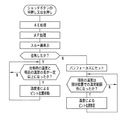
次に、第6実施形態について、図1,図4及び図9を参照して説明する。この図9では、スルー画表示中であるものとする。AF処理が行われ、合焦した場合には、CPU21は、合焦時の温度と現在の温度との差が1℃以上になるか否かを観測し、1℃以上になったら更に合焦時の温度と現在の温度との差が規定限界値(例えば±10℃)以内か否かを見る。この規定限界値内である場合には、ルックアップテーブル42bを参照して、フォーカスレンズを移動してピント位置を修正する。
【0058】
また、規定限界値を超えている場合には、急激な温度変化があることを示しているので、温度センサの追従性を考慮して、ズームレンズ24をパンフォーカスにセットする。また、AF処理によって合焦しない場合もズームレンズ24をパンフォーカスにセットする。そして、ルックアップテーブル42aを参照して、現在の温度におけるピント位置の修正を行う。なお、図9では、AF処理の前処理については図示を省略しているが、図6〜図8に示すものと同様である。
【0059】
次に、第7実施形態について、図1,図4及び図10を参照して説明する。この図10では、スルー画表示中であるものとする。AF処理が行われ、合焦した場合には、CPU21は、合焦時の温度と現在の温度との差が1℃以上になったら合焦時から経過した時間が一定時間、例えば1分を超えた時点でズームレンズ24をパンフォーカスにセットし、ルックアップテーブル42aを参照して、現在の温度におけるピント位置の修正を行う。前記一定時間を超えない間は、ルックアップテーブル42bを参照して温度差によるピント位置の修正を行う。また、AF処理によって合焦しない場合には、ズームレンズ24をパンフォーカスにセットし、ルックアップテーブル42aを参照して、現在の温度におけるピント位置の修正を行う。なお、図10では、AF処理の前処理については図示を省略しているが、図6〜図8に示すものと同様である。
【0060】
以上説明した実施形態では、現在の温度Tが現状位置での温度範囲(T3+T4)/2<T<(T4+T5)/2を満たす場合には、ピント位置の修正は不要としたが、例えばT4(25℃)から±2℃の範囲ではピント位置の修正を不要とし、これを超えて変動した場合、ルックアップテーブル42aにない温度、例えば28℃に変動した場合には、CPUがルックアップテーブル42aから補完的に演算して、例えばニア(near)方向にピント位置が移動されるように3個のパルスを印加するというようにしてもよい。この場合、例えば、現在の温度Tが例えば32℃になった場合には、T5とT6のデータから演算する。
【0061】
また、表1,表2における数値によって、本発明が限定されることがないのはもちろんである。また、上記一定時間は、一例として1分としたが、この数値に本発明が限定されることがないのはもちろんである。
【0062】
【発明の効果】
以上詳細に説明したように、本発明のデジタルカメラは、撮影レンズをパンフォーカスにして電子ビューファインダにスルー画表示するとともに、撮影レンズの温度を測り、撮影レンズの温度に対する撮影レンズのピント修正量を表す温度ルックアップテーブルを参照して撮影レンズのピント位置を修正するので、温度変化があってもスルー画をピントよく表示できる。
【0063】
また、電子ビューファインダにスルー画表示し、電源投入に伴ってオートフォーカス手段を作動させるとともに、撮影レンズの温度を測り、電源投入時の撮影レンズの温度とその後に変化した撮影レンズの温度との差に応じて撮影レンズのピント位置を修正するので、電源投入で撮影レンズのピント合わせができ、更にその後に温度変化があってもスルー画をピントよく表示できる。
【0064】
また、電子ビューファインダにスルー画表示し、シャッタボタンの半押し又は全押しによりオートフォーカス手段を作動させるとともに、撮影レンズの温度を測り、オートフォーカス手段による合焦時の撮影レンズの温度とその後に変化した撮影レンズの温度との差に応じて撮影レンズのピント位置を修正するので、温度変化があってもスルー画をピントよく表示できる。
【0065】
また、電子ビューファインダにスルー画表示し、シャッタボタンの半押し又は全押しによりオートフォーカス手段を作動させるとともに、撮影レンズの温度を測り、シャッタボタンの半押しを継続する間に、オートフォーカス手段による合焦時の撮影レンズの温度とその後に変化した撮影レンズの温度との差に応じて撮影レンズのピント位置を修正するので、温度変化があってもスルー画をピントよく表示できる。
【0066】
また、撮影レンズのオートフォーカスが不成功であった場合に、撮影レンズをパンフォーカスにするとともに、撮影レンズの温度に対する撮影レンズのピント修正量を表す温度ルックアップテーブルを参照して撮影レンズのピント位置を修正するので、撮影レンズが非合焦であっても、また温度変化があってもスルー画をピントよく表示できる。
【0067】
また、電子ビューファインダにスルー画表示し、シャッタボタンの半押し又は全押しによりオートフォーカス手段を作動させるとともに、撮影レンズの温度を測り、撮影レンズの温度が温度ルックアップテーブルを参照して撮影レンズのピント修正を行うべき温度である場合に、撮影レンズをパンフォーカスにするとともに温度ルックアップテーブルを参照して撮影レンズのピント位置を修正するので、温度変化があってもスルー画をピントよく表示できる。
【0068】
また、電子ビューファインダにスルー画表示し、シャッタボタンの半押し又は全押しによりオートフォーカス手段を作動させるとともに、撮影レンズの温度を測り、オートフォーカス手段による合焦時の撮影レンズの温度とその後に変化した撮影レンズの温度との差が予め決められた限界値を超えた場合に、撮影レンズをパンフォーカスにするとともに、温度ルックアップテーブルを参照して撮影レンズのピント位置を修正するので、急激な温度変化があってもスルー画をピントよく表示できる。
【0069】
また、電子ビューファインダにスルー画表示し、シャッタボタンの半押し又は全押しによりオートフォーカス手段を作動させるとともに、撮影レンズの温度を測り、オートフォーカス手段による合焦時から一定時間が経過した後、撮影レンズをパンフォーカスにするとともに、温度ルックアップテーブルを参照して撮影レンズのピント位置を修正するので、時間制限を設けることで非パンフォーカス状態の時間を短くでき、温度変化があってもスルー画をピントよく表示できる。
【図面の簡単な説明】
【図1】第1実施形態に係るデジタルカメラの背面斜視図である。
【図2】第1実施形態に係るデジタルカメラの電気構成を示すブロック図である。
【図3】第1実施形態に係るスルー画表示のシーケンスを示すフローチャートである。
【図4】第2実施形態に係るデジタルカメラの電気構成を示すブロック図である。
【図5】第2実施形態に係るスルー画表示のシーケンスを示すフローチャートである。
【図6】第3実施形態に係るスルー画表示のシーケンスを示すフローチャートである。
【図7】第4実施形態に係るスルー画表示のシーケンスを示すフローチャートである。
【図8】第5実施形態に係るスルー画表示のシーケンスを示すフローチャートである。
【図9】第6実施形態に係るスルー画表示のシーケンスを示すフローチャートである。
【図10】第7実施形態に係るスルー画表示のシーケンスを示すフローチャートである。
【符号の説明】
10,60 デジタルカメラ
12 レンズ鏡筒
13 電源ボタン
14 シャッタボタン
16 ズームボタン
19 液晶パネル
21 CPU
24 ズームレンズ
25 温度センサ
28 レンズ駆動機構
33 CCD
42 フラッシュメモリ
42a,42b ルックアップテーブル[0001]
BACKGROUND OF THE INVENTION
The present invention relates to a digital camera, and more particularly to a digital camera that can display a through image with good focus even when there is a temperature change.
[0002]
[Prior art]
Digital cameras that record image data of captured images as digital data on a memory card using a solid-state imaging device such as a CCD or a CMOS image sensor have become widespread. Many digital cameras are provided with an electronic viewfinder that reproduces an image captured by a solid-state imaging device in real time during framing and displays the image as a through image on a liquid crystal panel.
[0003]
Digital cameras with a relatively high price range are equipped with continuous AF, and the electronic viewfinder's display screen focuses in real time and always displays a sharp through image. In a model belonging to a low price range, the photographic lens is a fixed focus type and is not equipped with a continuous AF.
[0004]
In addition, in digital cameras belonging to a relatively low price range, in order to further reduce the cost and reduce the size and weight, the taking lens is changed from a glass lens to a plastic lens. However, the plastic lens has a disadvantage that the focal length fluctuates greatly due to the temperature change because the change in the refractive index due to the temperature change is as large as about 100 times that of the glass lens.
[0005]
For this reason, for example, in the fixed-focus camera described in Patent Document 1, a fixed-focus imaging lens or a solid-state imaging device is provided so as to be movable in the imaging optical axis direction, and a temperature sensor is attached to the outer peripheral surface of the lens barrel. Information indicating the temperature of the barrel is output to the CPU, and the CPU moves the CCD or the photographing lens based on the temperature information to change the distance between the CCD and the photographing lens, thereby focusing on the thermal expansion and contraction of the lens barrel. The deviation is corrected.
[0006]
[Patent Document 1]
JP-A-8-114736
[0007]
[Problems to be solved by the invention]
By the way, digital cameras with an intermediate price range are equipped with an autofocus mechanism, and focus is performed during actual shooting. However, in live view display, there are many cameras that do not focus using the shooting lens as pan focus. . However, if the photographic lens is a plastic lens as described above, the photographic lens is likely to be out of focus due to a temperature change, and the through image displayed on the electronic viewfinder may be out of focus. Note that Patent Document 1 does not describe a through image.
[0008]
It is an object of the present invention to provide a digital camera that can display a through image with good focus even when there is a temperature change.
[0009]
[Means for Solving the Problems]
In order to achieve the above object, a digital camera of the present invention is captured by an imaging means for obtaining a photographed image by subjecting a subject image formed by a photographing lens to photoelectric conversion, and taking the photographing lens as a pan focus. In a digital camera provided with an electronic viewfinder that reproduces a frame in real time and displays it as a through image, temperature measuring means for measuring the temperature of the photographing lens, and a temperature representing a focus correction amount of the photographing lens with respect to the temperature of the photographing lens A lookup table and control means for correcting the focus position of the photographing lens with reference to the temperature lookup table are provided.
[0010]
Further, an imaging unit that photoelectrically converts a subject image formed by a photographing lens to obtain a captured image, an electronic viewfinder that reproduces a frame captured by the imaging unit in real time and displays it as a through image, and a subject In a digital camera including an autofocus unit that measures the distance and focuses the photographing lens, a temperature measuring unit that measures the temperature of the photographing lens, and an initial focusing unit that operates the autofocus unit when the power is turned on. And a temperature difference lookup table that represents the focus correction amount of the photographic lens according to the difference between the temperature of the photographic lens at the time of power-on and the temperature of the photographic lens that has changed thereafter, and this temperature difference lookup table. And a control means for correcting the focus position of the photographing lens.
[0011]
In addition, an image pickup unit that photoelectrically converts a subject image formed by the shooting lens to obtain a shot image, an electronic viewfinder that reproduces a frame captured by the image pickup unit in real time and displays it as a through image, and a shutter button In a digital camera including an autofocus unit that automatically focuses the photographing lens by half-pressing or full-pressing, a temperature measuring unit that measures the temperature of the photographing lens, and a photographing lens at the time of focusing by the autofocusing unit A temperature difference look-up table that indicates the amount of correction of the focus of the taking lens according to the difference between the temperature of the taking lens and the temperature of the taking lens that has changed thereafter, and the focus position of the taking lens is corrected with reference to this temperature difference look-up table And a control means.
[0012]
In addition, an image pickup unit that photoelectrically converts a subject image formed by the shooting lens to obtain a shot image, an electronic viewfinder that reproduces a frame captured by the image pickup unit in real time and displays it as a through image, and a shutter button In a digital camera including an autofocus unit that automatically focuses the photographing lens by half-pressing or full-pressing, a temperature measuring unit that measures the temperature of the photographing lens, and a photographing lens at the time of focusing by the autofocusing unit The temperature difference look-up table showing the focus correction amount of the taking lens according to the difference between the temperature of the taking lens and the temperature of the taking lens changed thereafter, and this temperature difference look-up table while the shutter button is half-pressed A control means for correcting the focus position of the photographing lens is provided.
[0013]
In addition, when the focusing of the photographic lens by the autofocus unit is unsuccessful, the control unit sets the photographic lens to pan focus, and also displays a temperature look indicating the focus correction amount of the photographic lens with respect to the temperature of the photographic lens. The focus position of the photographing lens is corrected with reference to the up table.
[0014]
In addition, an image pickup unit that photoelectrically converts a subject image formed by the shooting lens to obtain a shot image, an electronic viewfinder that reproduces a frame captured by the image pickup unit in real time and displays it as a through image, and a shutter button In a digital camera including an autofocus unit that automatically focuses the photographing lens by half-pressing or full-pressing, a temperature measuring unit that measures the temperature of the photographing lens, and a focus correction of the photographing lens with respect to the temperature of the photographing lens A temperature look-up table representing the amount, and when the temperature of the photographing lens output from the temperature measuring means is a temperature at which the photographing lens focus should be corrected with reference to the temperature look-up table, the photographing lens is pan-focused And refer to the temperature lookup table. It is provided with a control means for correcting the focus position of the shadow lens.
[0015]
In addition, an image pickup unit that photoelectrically converts a subject image formed by the shooting lens to obtain a shot image, an electronic viewfinder that reproduces a frame captured by the image pickup unit in real time and displays it as a through image, and a shutter button In a digital camera including an autofocus unit that automatically focuses the photographing lens by half-pressing or full-pressing, a temperature measuring unit that measures the temperature of the photographing lens, and a photographing lens at the time of focusing by the autofocusing unit Temperature difference look-up table representing the focus correction amount of the taking lens according to the difference between the temperature of the taking lens and the temperature of the taking lens changed thereafter, and a temperature look-up table representing the focus correction amount of the taking lens with respect to the temperature of the taking lens The photographic lens temperature at the time of focusing and the photographic lens that changed after that. And a control means for correcting the focus position of the photographic lens with reference to the temperature look-up table, when the difference from the temperature of the lens exceeds a predetermined limit value. It is a thing.
[0016]
In addition, an image pickup unit that photoelectrically converts a subject image formed by the shooting lens to obtain a shot image, an electronic viewfinder that reproduces a frame captured by the image pickup unit in real time and displays it as a through image, and a shutter button In a digital camera including an autofocus unit that automatically focuses the photographing lens by half-pressing or full-pressing, a temperature measuring unit that measures the temperature of the photographing lens, and a photographing lens at the time of focusing by the autofocusing unit Temperature difference look-up table representing the focus correction amount of the taking lens according to the difference between the temperature of the taking lens and the temperature of the taking lens changed thereafter, and a temperature look-up table representing the focus correction amount of the taking lens with respect to the temperature of the taking lens And a certain amount of time has elapsed since the in-focus means After, as well as the taking lens to the pan-focus, is provided with a control means for correcting the focus position of the photographing lens by referring to the temperature lookup tables.
[0017]
DETAILED DESCRIPTION OF THE INVENTION
In FIG. 1 showing the appearance of the first embodiment of the present invention, a
[0018]
The mode selection lever 18 selects various modes such as a shooting mode for shooting, a playback mode for playing back a shot image, and a setup mode for making various settings. The general-
[0019]
The
[0020]
FIG. 2 is a block diagram showing the configuration of the
[0021]
The
[0022]
The
[0023]
The
[0024]
When displaying a through image, the aperture diameter of the
[0025]
Behind the photographic optical system, a
[0026]
The
[0027]
An analog imaging signal captured from the
[0028]
The ADC generates image data by digitally converting an analog signal. This image data is CCD-RAW data having R, G, and B density values for each pixel, and this CCD-RAW data is input to a DSP (Digital Signal Processor) 41. The analog
[0029]
The image data captured from the
The through image is captured at a predetermined frame rate (for example, 30 frames per second) while the shooting mode is selected. Further, since the through image is a display image, the number of pixels is smaller than that of the main image. When a shooting instruction is issued by fully pressing the
[0030]
The
[0031]
Further, the
[0032]
[Table 1]
The focal lengths Z1, Z2, Z3,... Are, for example, 10 focal lengths arbitrarily selected from the zooming range of the
[0034]
As shown in Table 1, in the lookup table 42a, the current temperature T of the
[0035]
The
[0036]
The
[0037]
The
[0038]
The
[0039]
The VRAM 40 is a memory for image output to the
[0040]
The operation of the first embodiment configured as described above will be described with reference to the flowchart shown in FIG. Immediately after the
[0041]
Subsequently, the
[0042]
The user performs framing while zooming the
[0043]
The
[0044]
When the current temperature T does not satisfy the temperature range (T3 + T4) / 2 <T <(T4 + T5) / 2, for example, when the current temperature T reaches T5 (30 ° C.), the
[0045]
Further, when the current temperature T reaches T6 (35 ° C.), seven pulse numbers are applied to the stepping motor (+13 with reference to T4). Thereafter, when the current temperature T returns to the temperature range (T3 + T4) / 2 <T <(T4 + T5) / 2, 13 pulses for moving the focus lens in the inf (inf.) Direction are stepped. Apply to the motor.
[0046]
The
[0047]
The photographer performs framing while viewing the through image displayed on the
[0048]
Next, the
[0049]
[Table 2]
The operation of the second embodiment will be described with reference to the flowchart of FIG. After the
[0051]
When the
[0052]
Next, a third embodiment will be described with reference to FIGS. A through image is displayed after AE processing and AF processing are performed in response to half-press or full-press of the
[0053]
If the focus is not achieved by the AF process, the
[0054]
Next, 4th Embodiment is described with reference to FIG.1, FIG4 and FIG.7. A through image is displayed after AE processing and AF processing are performed in response to half-press or full-press of the
[0055]
Next, a fifth embodiment will be described with reference to FIGS. In response to half-pressing of the
[0056]
If the focus is not achieved by AF processing, the
[0057]
Next, a sixth embodiment will be described with reference to FIGS. In FIG. 9, it is assumed that a through image is being displayed. When AF processing is performed and in-focus, the
[0058]
If the specified limit value is exceeded, it indicates that there is a rapid temperature change, so the
[0059]
Next, a seventh embodiment will be described with reference to FIGS. In FIG. 10, it is assumed that a through image is being displayed. When AF processing is performed and in-focus is achieved, the
[0060]
In the embodiment described above, when the current temperature T satisfies the temperature range (T3 + T4) / 2 <T <(T4 + T5) / 2 at the current position, it is not necessary to correct the focus position. 25 ° C.) to ± 2 ° C., correction of the focus position is not necessary, and if it fluctuates beyond this, if the temperature fluctuates beyond the look-up table 42a, for example, 28 ° C., the CPU detects the look-up table 42a. For example, three pulses may be applied so that the focus position is moved in the near direction. In this case, for example, when the current temperature T becomes 32 ° C., for example, the calculation is performed from the data of T5 and T6.
[0061]
Of course, the present invention is not limited by the numerical values in Tables 1 and 2. Moreover, although the said fixed time was made into 1 minute as an example, of course, this invention is not limited to this numerical value.
[0062]
【The invention's effect】
As described in detail above, the digital camera of the present invention displays the through image on the electronic viewfinder with the photographing lens as pan focus, measures the temperature of the photographing lens, and adjusts the focus correction amount of the photographing lens with respect to the temperature of the photographing lens. Since the focus position of the photographic lens is corrected with reference to the temperature look-up table indicating, a through image can be displayed with good focus even if the temperature changes.
[0063]
In addition, a live view is displayed on the electronic viewfinder, the autofocus unit is activated when the power is turned on, the temperature of the photographic lens is measured, and the temperature of the photographic lens when the power is turned on and the temperature of the photographic lens that has changed thereafter are displayed. Since the focus position of the photographic lens is corrected according to the difference, the photographic lens can be focused when the power is turned on, and a through image can be displayed with good focus even if there is a temperature change thereafter.
[0064]
In addition, through images are displayed on the electronic viewfinder, and the autofocus unit is activated by half-pressing or full-pressing the shutter button, and the temperature of the photographic lens is measured. Since the focus position of the photographic lens is corrected according to the difference between the changed temperature of the photographic lens, the through image can be displayed with good focus even if the temperature changes.
[0065]
In addition, a through image is displayed on the electronic viewfinder, and the autofocus unit is activated by half-pressing or full-pressing the shutter button, the temperature of the photographing lens is measured, and the auto-focusing unit keeps pressing the shutter button halfway. Since the focus position of the photographic lens is corrected in accordance with the difference between the temperature of the photographic lens at the time of focusing and the temperature of the photographic lens that has changed thereafter, a through image can be displayed with good focus even if the temperature changes.
[0066]
In addition, if auto-focusing of the taking lens is unsuccessful, the taking lens is set to pan focus, and the focus of the taking lens is referred to by referring to a temperature look-up table that shows the amount of focus correction of the taking lens with respect to the taking lens temperature Since the position is corrected, a through image can be displayed with good focus even if the taking lens is out of focus or there is a temperature change.
[0067]
In addition, a through image is displayed on the electronic viewfinder, and the auto focus unit is activated by half-pressing or full-pressing the shutter button, and the temperature of the photographing lens is measured, and the temperature of the photographing lens is referred to the temperature lookup table. When the temperature is to be corrected, the shooting lens is set to pan focus and the focus position of the shooting lens is corrected with reference to the temperature lookup table, so that the through image is displayed well even if there is a temperature change. it can.
[0068]
In addition, through images are displayed on the electronic viewfinder, and the autofocus unit is activated by half-pressing or full-pressing the shutter button, and the temperature of the photographic lens is measured. When the difference between the temperature of the changed photographic lens exceeds a predetermined limit, the photographic lens is pan-focused and the focus position of the photographic lens is corrected by referring to the temperature lookup table. A through image can be displayed in focus even if there is a significant temperature change.
[0069]
In addition, through images are displayed on the electronic viewfinder, the autofocus unit is activated by half-pressing or full-pressing the shutter button, the temperature of the photographing lens is measured, and after a certain time has elapsed since the in-focus state by the autofocus unit, Since the shooting lens is set to pan focus and the focus position of the shooting lens is corrected by referring to the temperature look-up table, the time in non-pan focus can be shortened by setting a time limit. The image can be displayed in focus.
[Brief description of the drawings]
FIG. 1 is a rear perspective view of a digital camera according to a first embodiment.
FIG. 2 is a block diagram showing an electrical configuration of the digital camera according to the first embodiment.
FIG. 3 is a flowchart showing a through image display sequence according to the first embodiment.
FIG. 4 is a block diagram showing an electrical configuration of a digital camera according to a second embodiment.
FIG. 5 is a flowchart showing a through image display sequence according to the second embodiment.
FIG. 6 is a flowchart showing a through image display sequence according to the third embodiment.
FIG. 7 is a flowchart showing a through image display sequence according to the fourth embodiment.
FIG. 8 is a flowchart showing a through image display sequence according to a fifth embodiment.
FIG. 9 is a flowchart showing a through image display sequence according to the sixth embodiment.
FIG. 10 is a flowchart showing a through image display sequence according to the seventh embodiment.
[Explanation of symbols]
10, 60 Digital camera
12 Lens barrel
13 Power button
14 Shutter button
16 Zoom button
19 LCD panel
21 CPU
24 Zoom lens
25 Temperature sensor
28 Lens drive mechanism
33 CCD
42 Flash memory
42a, 42b Look-up table
Claims (8)
前記撮影レンズの温度を測る温度測定手段と、前記撮影レンズの温度に対する撮影レンズのピント修正量を表す温度ルックアップテーブルと、この温度ルックアップテーブルを参照して撮影レンズのピント位置を修正する制御手段とを設けたことを特徴とするデジタルカメラ。An imaging unit that photoelectrically converts a subject image formed by a photographic lens to obtain a photographic image, and an electronic view finder that reproduces a frame captured by the imaging unit in real time with the photographic lens being pan-focused and displays it as a through image In a digital camera equipped with
Temperature measuring means for measuring the temperature of the photographing lens, a temperature look-up table indicating a focus correction amount of the photographing lens with respect to the temperature of the photographing lens, and control for correcting the focus position of the photographing lens with reference to the temperature lookup table And a digital camera.
前記撮影レンズの温度を測る温度測定手段と、前記オートフォーカス手段を電源投入に伴って作動させる初期合焦手段と、前記電源投入時の撮影レンズの温度とその後に変化した撮影レンズの温度との差に応じて撮影レンズのピント修正量を表す温度差ルックアップテーブルと、この温度差ルックアップテーブルを参照して撮影レンズのピント位置を修正する制御手段とを設けたことを特徴とするデジタルカメラ。An imaging unit that photoelectrically converts a subject image formed by a photographic lens to obtain a captured image, an electronic viewfinder that reproduces a frame captured by the imaging unit in real time and displays it as a through image, and a distance between the subject In a digital camera equipped with an autofocus means for measuring and focusing the taking lens,
A temperature measuring means for measuring the temperature of the photographing lens, an initial focusing means for operating the autofocus means when the power is turned on, a temperature of the photographing lens at the time of turning on the power, and a temperature of the photographing lens changed thereafter. A digital camera comprising a temperature difference look-up table representing a focus correction amount of the photographing lens in accordance with the difference and a control means for correcting the focus position of the photographing lens with reference to the temperature difference look-up table .
前記撮影レンズの温度を測る温度測定手段と、前記オートフォーカス手段による合焦時の撮影レンズの温度とその後に変化した撮影レンズの温度との差に応じて撮影レンズのピント修正量を表す温度差ルックアップテーブルと、この温度差ルックアップテーブルを参照して撮影レンズのピント位置を修正する制御手段とを設けたことを特徴とするデジタルカメラ。Imaging means for photoelectrically converting a subject image formed by a photographing lens to obtain a photographed image, an electronic viewfinder for reproducing a frame captured by the imaging means in real time and displaying it as a through image, and half-pressing a shutter button Or in a digital camera equipped with autofocus means for automatically focusing the photographic lens by pressing fully,
A temperature measurement unit that measures the temperature of the photographing lens, and a temperature difference that represents a focus correction amount of the photographing lens according to a difference between the temperature of the photographing lens at the time of focusing by the autofocus unit and the temperature of the photographing lens that has changed after that. A digital camera comprising a look-up table and control means for correcting the focus position of the taking lens with reference to the temperature difference look-up table.
前記撮影レンズの温度を測る温度測定手段と、前記オートフォーカス手段による合焦時の撮影レンズの温度とその後に変化した撮影レンズの温度との差に応じて撮影レンズのピント修正量を表す温度差ルックアップテーブルと、シャッタボタンの半押しを継続する間に、この温度差ルックアップテーブルを参照して撮影レンズのピント位置を修正する制御手段とを設けたことを特徴とするデジタルカメラ。Imaging means for photoelectrically converting a subject image formed by a photographing lens to obtain a photographed image, an electronic viewfinder for reproducing a frame captured by the imaging means in real time and displaying it as a through image, and half-pressing a shutter button Or in a digital camera equipped with autofocus means for automatically focusing the photographic lens by pressing fully,
A temperature measurement unit that measures the temperature of the photographing lens, and a temperature difference that represents a focus correction amount of the photographing lens according to a difference between the temperature of the photographing lens at the time of focusing by the autofocus unit and the temperature of the photographing lens that has changed after that. A digital camera comprising a look-up table and control means for correcting the focus position of the photographing lens with reference to the temperature difference look-up table while the shutter button is half-pressed.
前記撮影レンズの温度を測る温度測定手段と、前記撮影レンズの温度に対する撮影レンズのピント修正量を表す温度ルックアップテーブルと、前記温度測定手段から出力された撮影レンズの温度が温度ルックアップテーブルを参照して撮影レンズのピント修正を行うべき温度である場合に、前記撮影レンズをパンフォーカスにするとともに、前記温度ルックアップテーブルを参照して撮影レンズのピント位置を修正する制御手段とを設けたことを特徴とするデジタルカメラ。Imaging means for photoelectrically converting a subject image formed by a photographing lens to obtain a photographed image, an electronic viewfinder for reproducing a frame captured by the imaging means in real time and displaying it as a through image, and half-pressing a shutter button Or in a digital camera equipped with autofocus means for automatically focusing the photographic lens by pressing fully,
A temperature measuring means for measuring the temperature of the photographing lens; a temperature lookup table indicating a focus correction amount of the photographing lens with respect to the temperature of the photographing lens; and a temperature of the photographing lens output from the temperature measuring means is a temperature lookup table. And a control means for correcting the focus position of the photographic lens with reference to the temperature look-up table as well as setting the photographic lens to pan focus when the temperature is to be corrected by referring to the photographic lens. A digital camera characterized by that.
前記撮影レンズの温度を測る温度測定手段と、前記オートフォーカス手段による合焦時の撮影レンズの温度とその後に変化した撮影レンズの温度との差に応じて撮影レンズのピント修正量を表す温度差ルックアップテーブルと、前記撮影レンズの温度に対する撮影レンズのピント修正量を表す温度ルックアップテーブルと、前記合焦時の撮影レンズの温度とその後に変化した撮影レンズの温度との差が予め決められた限界値を超えた場合に、前記撮影レンズをパンフォーカスにするとともに、前記温度ルックアップテーブルを参照して撮影レンズのピント位置を修正する制御手段とを設けたことを特徴とするデジタルカメラ。Imaging means for photoelectrically converting a subject image formed by a photographing lens to obtain a photographed image, an electronic viewfinder for reproducing a frame captured by the imaging means in real time and displaying it as a through image, and half-pressing a shutter button Or in a digital camera equipped with autofocus means for automatically focusing the photographic lens by pressing fully,
A temperature measurement unit that measures the temperature of the photographing lens, and a temperature difference that represents a focus correction amount of the photographing lens according to a difference between the temperature of the photographing lens at the time of focusing by the autofocus unit and the temperature of the photographing lens that has changed after that. The difference between the look-up table, the temperature look-up table indicating the focus correction amount of the taking lens with respect to the temperature of the taking lens, and the temperature of the taking lens at the time of focusing and the temperature of the taking lens changed thereafter is determined in advance. And a control means for adjusting the focus position of the photographing lens with reference to the temperature look-up table when the photographing lens is pan-focused when the limit value is exceeded.
前記撮影レンズの温度を測る温度測定手段と、前記オートフォーカス手段による合焦時の撮影レンズの温度とその後に変化した撮影レンズの温度との差に応じて撮影レンズのピント修正量を表す温度差ルックアップテーブルと、前記撮影レンズの温度に対する撮影レンズのピント修正量を表す温度ルックアップテーブルと、前記オートフォーカス手段による合焦時から一定時間が経過した後、前記撮影レンズをパンフォーカスにするとともに、前記温度ルックアップテーブルを参照して撮影レンズのピント位置を修正する制御手段とを設けたことを特徴とするデジタルカメラ。Imaging means for photoelectrically converting a subject image formed by a photographing lens to obtain a photographed image, an electronic viewfinder for reproducing a frame captured by the imaging means in real time and displaying it as a through image, and half-pressing a shutter button Or in a digital camera equipped with autofocus means for automatically focusing the photographic lens by pressing fully,
A temperature measurement unit that measures the temperature of the photographing lens, and a temperature difference that represents a focus correction amount of the photographing lens according to a difference between the temperature of the photographing lens at the time of focusing by the autofocus unit and the temperature of the photographing lens that has changed after that. A look-up table, a temperature look-up table that represents the amount of focus correction of the taking lens with respect to the temperature of the taking lens, and after a fixed time has elapsed from the time of focusing by the autofocus means, the taking lens is set to pan focus And a control means for correcting the focus position of the taking lens with reference to the temperature look-up table.
Priority Applications (1)
| Application Number | Priority Date | Filing Date | Title |
|---|---|---|---|
| JP2003080403A JP2004287183A (en) | 2003-03-24 | 2003-03-24 | Digital camera |
Applications Claiming Priority (1)
| Application Number | Priority Date | Filing Date | Title |
|---|---|---|---|
| JP2003080403A JP2004287183A (en) | 2003-03-24 | 2003-03-24 | Digital camera |
Publications (1)
| Publication Number | Publication Date |
|---|---|
| JP2004287183A true JP2004287183A (en) | 2004-10-14 |
Family
ID=33294265
Family Applications (1)
| Application Number | Title | Priority Date | Filing Date |
|---|---|---|---|
| JP2003080403A Pending JP2004287183A (en) | 2003-03-24 | 2003-03-24 | Digital camera |
Country Status (1)
| Country | Link |
|---|---|
| JP (1) | JP2004287183A (en) |
Cited By (7)
| Publication number | Priority date | Publication date | Assignee | Title |
|---|---|---|---|---|
| JP2008042248A (en) * | 2006-08-01 | 2008-02-21 | Fujifilm Corp | Electronic camera and its exposure control method |
| WO2008078150A1 (en) * | 2006-12-22 | 2008-07-03 | Nokia Corporation | Calculating camera lens position information |
| JP2010267086A (en) * | 2009-05-14 | 2010-11-25 | Sony Corp | Vein imaging apparatus, displacement interpolation method, and program |
| CN102256054A (en) * | 2011-01-19 | 2011-11-23 | 深圳市保千里电子有限公司 | Camera capable of being normally started at low temperature and realization method thereof |
| US8068166B2 (en) | 2007-10-31 | 2011-11-29 | Hitachi, Ltd. | Zoom camera with manual focus function |
| JP2014082590A (en) * | 2012-10-15 | 2014-05-08 | Canon Inc | Imaging apparatus, control method and program thereof |
| WO2017104774A1 (en) * | 2015-12-18 | 2017-06-22 | 旭化成エレクトロニクス株式会社 | Drive device, lens unit, device, correction method, and program |
-
2003
- 2003-03-24 JP JP2003080403A patent/JP2004287183A/en active Pending
Cited By (11)
| Publication number | Priority date | Publication date | Assignee | Title |
|---|---|---|---|---|
| JP2008042248A (en) * | 2006-08-01 | 2008-02-21 | Fujifilm Corp | Electronic camera and its exposure control method |
| WO2008078150A1 (en) * | 2006-12-22 | 2008-07-03 | Nokia Corporation | Calculating camera lens position information |
| US8068166B2 (en) | 2007-10-31 | 2011-11-29 | Hitachi, Ltd. | Zoom camera with manual focus function |
| JP2010267086A (en) * | 2009-05-14 | 2010-11-25 | Sony Corp | Vein imaging apparatus, displacement interpolation method, and program |
| CN102256054A (en) * | 2011-01-19 | 2011-11-23 | 深圳市保千里电子有限公司 | Camera capable of being normally started at low temperature and realization method thereof |
| CN102256054B (en) * | 2011-01-19 | 2012-09-19 | 深圳市保千里电子有限公司 | Camera capable of being normally started at low temperature and realization method thereof |
| JP2014082590A (en) * | 2012-10-15 | 2014-05-08 | Canon Inc | Imaging apparatus, control method and program thereof |
| WO2017104774A1 (en) * | 2015-12-18 | 2017-06-22 | 旭化成エレクトロニクス株式会社 | Drive device, lens unit, device, correction method, and program |
| JPWO2017104774A1 (en) * | 2015-12-18 | 2018-08-09 | 旭化成エレクトロニクス株式会社 | Drive device, lens unit, device, correction method, and program |
| CN108700723A (en) * | 2015-12-18 | 2018-10-23 | 旭化成微电子株式会社 | Driving device, lens unit, equipment, bearing calibration and program |
| US11042041B2 (en) | 2015-12-18 | 2021-06-22 | Asahi Kasei Microdevices Corporation | Lens driving apparatus, method, and device having correction of temperature information according to drive current |
Similar Documents
| Publication | Publication Date | Title |
|---|---|---|
| JP4528235B2 (en) | Digital camera | |
| JP2019054461A (en) | Imaging apparatus and imaging method | |
| JP3823921B2 (en) | Imaging device | |
| JP3395770B2 (en) | Digital still camera | |
| KR20100039430A (en) | Image processor, image processing method, digital camera, and imaging apparatus | |
| JP4533735B2 (en) | Stereo imaging device | |
| JP2010268388A (en) | Imaging apparatus | |
| JP2007311861A (en) | Photographic apparatus and method | |
| JP5967865B2 (en) | IMAGING DEVICE, IMAGING DEVICE CONTROL METHOD, AND PROGRAM | |
| JP2003018438A (en) | Imaging apparatus | |
| JP2006091915A (en) | Imaging apparatus | |
| JP2010154310A (en) | Compound-eye camera, and photographing method | |
| JP5011235B2 (en) | Imaging apparatus and imaging method | |
| JP2008053931A (en) | Imaging apparatus | |
| JP2006261929A (en) | Image pickup device | |
| JP5100410B2 (en) | Imaging apparatus and control method thereof | |
| JP4033456B2 (en) | Digital camera | |
| JPH0943507A (en) | Electric still camera and focusing control method thereof | |
| JP2007225897A (en) | Focusing position determination device and method | |
| JP2006217505A (en) | Photographing device | |
| JP2004287183A (en) | Digital camera | |
| JP2009223056A (en) | Photographic apparatus and method | |
| JP4767904B2 (en) | Imaging apparatus and imaging method | |
| JP2018011268A (en) | Imaging apparatus, image superimposition method, and program | |
| JPH09181954A (en) | Electronic still camera and method for focus-controlling the same |