JP3757385B2 - Film holding device in stretch wrapping machine - Google Patents
Film holding device in stretch wrapping machine Download PDFInfo
- Publication number
- JP3757385B2 JP3757385B2 JP2001273930A JP2001273930A JP3757385B2 JP 3757385 B2 JP3757385 B2 JP 3757385B2 JP 2001273930 A JP2001273930 A JP 2001273930A JP 2001273930 A JP2001273930 A JP 2001273930A JP 3757385 B2 JP3757385 B2 JP 3757385B2
- Authority
- JP
- Japan
- Prior art keywords
- film
- holding
- article
- stretch
- endless
- Prior art date
- Legal status (The legal status is an assumption and is not a legal conclusion. Google has not performed a legal analysis and makes no representation as to the accuracy of the status listed.)
- Expired - Fee Related
Links
Images


Description
【0001】
【発明の属する技術分野】
この発明は、保持されたストレッチフィルムに向けて物品を持ち上げてその上面を覆った後、物品の周縁から延出するフィルム端部を物品の底面側に折込むストレッチ包装機において、物品の上方に搬送されたストレッチフィルムに向けて物品が持ち上げられる際に、該フィルムを保持するフィルム保持装置に関するものである。
【0002】
【従来の技術】
トレー等の容器に商品を収容した物品をストレッチフィルムによってタイトに包装するストレッチ包装機では、原反ロールから引出されたストレッチフィルムを所定の長さで切断し、この切断されたストレッチフィルムの側縁部を挟持して物品の上方へ搬送するよう構成されている。
【0003】
前記ストレッチフィルムの搬送手段として、所定間隔離間するプーリ間に巻架した複数本の無端丸ベルトを上下に設け、上側の無端丸ベルトにおける下側の直線走行部分と、下側の無端丸ベルトにおける上側の直線走行部分とを、略同一面で交互に並ぶように配置し、これら丸ベルトの間でストレッチフィルムの側縁部を波状に挟持した状態で、上下の無端丸ベルトを互いに反対向きに回転させることにより、ストレッチフィルムを搬送するよう構成したものが知られている。
【0004】
そしてストレッチ包装機では、前記搬送手段による物品上方へのフィルム搬送が停止した後、該ストレッチフィルムに向けて物品が持ち上げられるよう構成される。このとき、ストレッチフィルムは保持手段で保持されるようになっており、例えば特開昭61−14112号公報に開示の保持手段は、前記両無端丸ベルトの直線走行部分を挟圧可能な押え部材と受圧板、および押え部材を動作させるソレノイド等とを具備している。すなわちこの保持手段では、物品が持ち上げられる際には、前述のようにしてストレッチフィルムの側縁部を挟持している状態の両無端丸ベルトの直線走行部分を押え部材と受圧板とで挟圧していて、無端丸ベルトと共に保持されたストレッチフィルムに物品を下から押付けることで、該フィルムが伸張されて物品の上面を覆うようになっている。次いで、物品の周縁から延出するフィルム端部を、折込み部材で物品の底面側に折込む最中の適宜タイミングで、該保持手段によるストレッチフィルムの保持を解除することでフィルム折込みが達成される。
【0005】
前記ストレッチフィルムの搬送手段としては、丸ベルトを用いたものの他に、平ベルトを用いたものもある。すなわちこの搬送手段は、所定間隔離間するプーリ間に巻架した無端平ベルトを上下に設け、上側の無端平ベルトにおける下側の直線走行部分と、下側の無端平ベルトにおける上側の直線走行部分とを対接するように配置し、これら平ベルトの間でストレッチフィルムの側縁部を挟持した状態で、上下の無端平ベルトを互いに反対向きに回転させることにより、ストレッチフィルムを搬送するよう構成される。
【0006】
前記無端平ベルトを用いる搬送手段を採用した、例えば特開平8−119212号公報に開示の保持手段は、前述した対接状態の無端平ベルトの直線走行部分を密着可能なクランプ部材と、このクランプ部材を作動させるソレノイド等とを具備している。そしてこの保持手段では、搬送手段により物品上方へのフィルム搬送が停止した後、このストレッチフィルムに向けて物品が持ち上げられる際には、対接状態の両無端平ベルトの直線走行部分をクランプ部材により密着していて、該無端平ベルトを介して保持されているストレッチフィルムに物品を下から押付けることで、該フィルムが伸張されて物品の上面を覆うようになっている。次いで、物品の周縁から延出するフィルム端部を折込み部材で物品の底面側に折込む最中の適宜タイミングで、該クランプ部材によるストレッチフィルムの保持を解除することでフィルム折込みが達成される。
【0007】
【発明が解決しようとする課題】
前述した何れの構成のフィルム保持手段においても、上下のベルトを挟圧することでストレッチフィルムを保持している。また、物品が持ち上げられる際には、ストレッチフィルムに物品を下から押付けることで該フィルムを伸張させなければならないので、このときにはベルトを強く挟圧し、上下のベルト間からストレッチフィルムが抜けないように設定してある。この場合に、ストレッチフィルムは粘着性を有しているので、ベルトに対する挟圧を止めてストレッチフィルムに対する保持を解除しても、該フィルムがベルトに付着したままとなり、フィルム折込み時にベルト間から良好に抜けないことがある。このようにストレッチフィルムに対する保持の解除が不完全であると、前記折込み部材がストレッチフィルムを破ってしまい、包装不良品が発生する問題がある。また、折込み部材に押されたストレッチフィルムが物品(トレー等)に強く押付けられることで該物品が破損し、この場合も包装不良品の発生を招く。
【0008】
【発明の目的】
この発明は、前述した従来の技術に内在している前記課題に鑑み、これを好適に解決するべく提案されたものであって、ストレッチフィルムに対する保持の解除を良好に行ない得るストレッチ包装機におけるフィルム保持装置を提供することを目的とする。
【0009】
【課題を解決するための手段】
前述した課題を解決し、所期の目的を好適に達成するため、本発明に係るストレッチ包装機におけるフィルム保持装置は、
フィルム展張部で保持したフィルムに向けて持ち上げた物品の上面を覆い、該物品の周縁から延出するフィルム端部を物品の底面側に折込むストレッチ包装機において、
前記フィルムの側縁部を上下の無端ベルトで挟持して前記フィルム展張部に搬送する一対の無端ベルトコンベヤと、
前記フィルム展張部において前記フィルムを前記上下の無端ベルトより内側で保持可能に配設された上下の保持部材を備えた一対の保持手段と、
前記両無端ベルトコンベヤに対応して設けられ、前記上下の無端ベルトを相対的に離間してフィルムの挟持を解除する解除手段とを備え、
前記一対の無端ベルトコンベヤによりフィルム展張部にフィルムが搬送された後のタイミングで、該フィルムを保持すると共に、フィルム端部の折込みに先立ち、前記各無端ベルトコンベヤにおける上下の無端ベルトによるフィルムの挟持を解除するよう前記保持手段と解除手段との夫々を作動制御するようにしたことを特徴とする。
【0010】
【発明の実施の形態】
次に、本発明に係るストレッチ包装機におけるフィルム保持装置につき、好適な実施例を挙げて、添付図面を参照しながら以下説明する。なお実施例では、ストレッチフィルムのフィルム展張部への水平な搬送方向を左右方向と称し、これと水平に交差する方向を前後方向と称するものとする。
【0011】
(フィルムの搬送機構について)
図1および図2に示すように、実施例に係るフィルム保持装置が採用されるストレッチ包装機の機枠10には、前後方向に離間して一対の搬送機構11,12が配設され、供給源としての原反ロール13から引出されてカッター14により切断された所定寸法のストレッチフィルムFは、両搬送機構11,12により前後方向の両側縁部を挟持された状態でフィルム展張部Sまで搬送されるよう構成される。なお、搬送機構11,12の基本的な構成は同一であるので、前側に配設される搬送機構11の構成についてのみ説明し、後側に配設される搬送機構12の同一部材には同じ符号を付して示すこととする。
【0012】
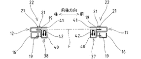
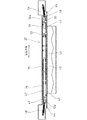
図12に示す如く、前記機枠10の左右方向に離間する位置に、フィルム搬送方向と直交する一対の案内軸15,15が配設され、両軸15,15間に、搬送機構11の左右方向に延在する搬送用フレーム16が摺動筒17,17を介して摺動可能に架設されて前後動可能に構成されている。この搬送用フレーム16には、図4に示す如く、その左右両端部近傍に下プーリ18,18が回転可能に枢支されると共に、両下プーリ18,18間には、その軸方向に所定間隔離間して複数(実施例では3本)の下無端丸ベルト19が巻掛けられている。また各下プーリ18の上側に上プーリ20が夫々回転可能に枢支されると共に、両上プーリ20,20間に、その軸方向に所定間隔離間して複数(実施例では2本)の上無端丸ベルト21が巻掛けられている。下無端丸ベルト19と上無端丸ベルト21とは、図6に示す如く、上無端丸ベルト21における下側の直線走行部分と、下無端丸ベルト19における上側の直線走行部分とが略同一面で前後方向に交互に並ぶように配置され、これら上下の無端丸ベルト19,21の間でストレッチフィルムFの側縁部を波状に挟持するよう構成される。また、上下のプーリ18,20には、噛合する従動歯車18a,20aが一体回転可能に配設されており、両プーリ18,20は相互に反対向きに回転するようになっている。そして、実施例では上下の無端丸ベルト19,21から無端ベルトコンベヤ22が構成される。なお、図4において符号23は、上無端丸ベルト21の巻掛け経路を変移させる遊転ローラを示す。
【0013】
前記機枠10の左右方向に離間する位置に、図3に示す如く、フィルム搬送方向と直交する一対の駆動軸24,24が配設され、各駆動軸24には、キー24aを介して軸方向への移動が許容された状態で一体的に回転する駆動歯車25が配設されている。この駆動歯車25は、前記対応する下プーリ18の従動歯車18aに噛合している。また、両駆動軸24,24における機枠10の後方に延出する軸端に従動プーリ24b,24bが一体回転可能に配設されると共に、両プーリ24b,24b間に無端ベルト26が巻掛けられている。この無端ベルト26は、機枠10に配設された走行用サーボモータ27により回転される駆動プーリ28にも巻掛けられており、該モータ27を所定方向に回転することで、駆動歯車25と従動歯車18aとの噛合作用下に、上無端丸ベルト21の下側直線走行部分と下無端丸ベルト19の上側直線走行部分とが同一方向に走行し、これによって側縁部が挟持されているストレッチフィルムFがフィルム展張部Sに向けて搬送されるよう構成される。なお、両搬送機構11,12によるストレッチフィルムFの搬送量は、走行用サーボモータ27が図示しない制御手段で制御されることで、物品(トレーに商品を収容したもの)29の大きさ(左右方向の長さ)によって変更される。また、駆動歯車25の軸端部に係合溝25aが形成され、該係合溝25aに前記搬送用フレーム16の対応する端部が係合し、後述するように搬送機構11が前後動する際には駆動歯車25が駆動軸24に沿って追従移動し、従動歯車18aとの噛合状態を維持し得るようになっている。
【0014】
(解除手段について)
前記搬送用フレーム16における各プーリ配設位置に近接する部位に、上下の無端丸ベルト19,21によるストレッチフィルムFの挟持を解除する解除手段30が夫々配設されている。各解除手段30は、図4および図5に示す如く、搬送用フレーム16に配設した支持軸31に揺動可能に枢支した揺動レバー32を備え、該レバー32の先端部には、各上無端丸ベルト21における下側直線走行部分の下方に臨む押上げローラ33が回転可能に配設されている。また、揺動レバー32に作動レバー34が一体的に揺動可能に配設されると共に、該作動レバー34には、搬送用フレーム16に配設された解除用ソレノイド35の上向きのロッド35aが連結してある。作動レバー34と搬送用フレーム16との間に板バネ36が弾力的に配設され、揺動レバー32を介して押上げローラ33は、常には上無端丸ベルト21の下側直線走行部分から下方に離間する退避位置に保持されるよう設定してある。そして、解除用ソレノイド35を励磁してロッド35aを磁力吸引することで、板バネ36の弾力に抗して揺動レバー32が押上げローラ33を上動するよう揺動し、該押上げローラ33の上部が上無端丸ベルト21の下側直線走行部分より上方の解除位置まで上動することで、押上げローラ33によって各上無端丸ベルト21の下側直線走行部分が下無端丸ベルト19の上側直線走行部分より上方に押上げられて、ストレッチフィルムFの挟持が解除されるようになっている(図7参照)。
【0015】
(保持機構について)
前記両搬送機構11,12の前後方向内側(両無端ベルトコンベヤ22,22の対向方向内側)に、ストレッチフィルムFの両側縁部を挟んで保持する保持機構37,38が配設されている。なお、保持機構37,38の基本的な構成は同一であるので、前側に配設される保持機構37の構成についてのみ説明し、後側に配設される保持機構38の同一部材には同じ符号を付して示すこととする。
【0016】
前記保持機構37は、図8に示す如く、前記両案内軸15,15に摺動筒39,39を介して前後方向に摺動可能な保持用フレーム40に、フィルム搬送経路を挟んで上側に位置する固定保持部材41と、該固定保持部材41の下側において、そのフィルム搬送方向(左右方向)中央に位置する中央可動保持部材42および該中央可動保持部材42の左右両側に位置する一対の側部可動保持部材43,43とが配設され、これら保持部材41,42,43,43はフィルム搬送方向に沿った形状に形成されている。中央可動保持部材42および両側部可動保持部材43,43は、夫々対応する作動機構44,45により固定保持部材41に対して離間する位置と当接する位置との間で開閉動可能に配設され、固定保持部材41と3個の可動保持部材42,43,43とでストレッチフィルムFの側端縁を、フィルム搬送方向で3分割された部位で挟むよう構成してある。実施例では、固定保持部材41とフィルム搬送方向で分割された3個の可動保持部材42,43,43とからストレッチフィルムFを挟んで保持する保持手段が構成される。なお、この保持手段、詳しくは保持手段がストレッチフィルムFを保持するフィルム保持領域(固定保持部材41と3個の可動保持部材42,43,43との当接領域)はそのフィルム搬送方向中央が、持ち上げられる物品29のフィルム搬送方向中央と対応するよう配設される。また、この保持手段、詳しくは前記フィルム保持領域のフィルム搬送方向長さは、当該ストレッチ包装機で包装可能な最大寸法の物品29の対応する左右長さより長く設定されている。
【0017】
前記中央可動保持部材42は、図8および図10に示す如く、保持用フレーム40に回動可能に枢支された略L形の第1中央レバー46の一端部に枢支されると共に、該中央レバー46の他端部が中央作動部材47の一端部に枢支されている。また中央作動部材47の他端部には、保持用フレーム40に回動可能に枢支された略L形の第2中央レバー49の一端部が枢支されると共に、該中央レバー49の他端部には、保持用フレーム40に配設された中央用ソレノイド51の上向きのロッド51aが連結してある。この中央作動部材47の他端部と保持用フレーム40との間に中央用コイルバネ48が張設され、該中央作動部材47は、常には第1中央レバー46を介して中央可動保持部材42を固定保持部材41から離間する退避位置に保持するよう設定されている。そして、中央用ソレノイド51を励磁してロッド51aを磁力吸引することで、第2中央レバー49および中央作動部材47を介して第1中央レバー46が所定方向に回動し、これによって中央可動保持部材42が固定保持部材41に近接してストレッチフィルムFの側端縁中央部を挟むよう構成される。実施例では、第1中央レバー46、中央作動部材47、中央用コイルバネ48、第2中央レバー49および中央用ソレノイド51から、中央可動保持部材42を開閉作動させる中央作動機構44が構成される。
【0018】
前記各側部可動保持部材43は、図8および図11に示す如く、保持用フレーム40に回動可能に枢支された略L形の第1側部レバー52の一端部に枢支されると共に、該側部レバー52の他端部が側部作動部材53に枢支されている。この側部作動部材53における前記中央用コイルバル48の配設側とは反対側を向く端部と、保持用フレーム40との間に側部用コイルバネ54が張設され、該側部作動部材53は、常には第1側部レバー52を介して側部可動保持部材43,43を固定保持部材41から離間する退避位置に保持するよう設定されている。また側部作動部材53には、保持用フレーム40に回動可能に枢支された略L形の第2側部レバー55の一端部が枢支されると共に、該側部レバー55の他端部には、保持用フレーム40に配設された側部用ソレノイド56の上向きのロッド56aが連結してある。そして、側部用ソレノイド56を励磁してロッド56aを磁力吸引することで、第2側部レバー55および側部作動部材53を介して第1側部レバー52,52が所定方向に回動し、これによって両側部可動保持部材43,43が固定保持部材41に近接してストレッチフィルムFを中央可動保持部材42の左右両側で挟むよう構成される。実施例では、第1側部レバー52,52、側部作動部材53、側部用コイルバネ54、第2側部レバー55および側部用ソレノイド56から、側部可動保持部材43,43を開閉作動させる側部作動機構45が構成される。
【0019】
前記固定保持部材41、前記中央可動保持部材42および側部可動保持部材43,43の各ストレッチフィルムFと接触する面(固定保持部材41の下面,可動保持部材42,43,43の上面)に、ストレッチフィルムFが付着しない材質のシート材79が夫々貼着してある。このシート材79は可撓性を有し、ストレッチフィルムFを保持部材41,42,43,43で挟む際のクッション材としても機能する。なお、シート材79を貼着するのに代えて、固定保持部材41と各可動保持部材42,43,43との対向面に、ストレッチフィルムFが付着することを防止し得る処理や加工、あるいは部材を取着することが可能である。
【0020】
(保持機構の予備伸張手段および張力減少手段について)
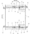
前記前後の保持機構37,38の間に臨む機枠10の左右両側に保持軸57が夫々配設され(図12参照)、各保持軸57には軸方向に離間して第1歯付きプーリ58と第2歯付きプーリ59が夫々回転可能に配設されている。図13に示す如く、第1歯付きプーリ58と対応する機枠10の前側に対をなす第1歯付きプーリ58が回転可能に配設され、両第1歯付きプーリ58,58間に巻掛けられた無端状の第1歯付きベルト60の適宜位置に前側の保持機構37の摺動筒39が固定されている。また第2歯付きプーリ59と対応する機枠10の後側に対をなす第2歯付きプーリ59が回転可能に配設され、両第2歯付きプーリ59,59間に巻掛けられた無端状の第2歯付きベルト61の適宜位置に後側の保持機構38の摺動筒39が固定されている。
【0021】
前側に位置する左右両側の第1歯付きプーリ58,58は、機枠10に配設された第1サーボモータ62にプーリ−ベルト等の第1連繋手段63により連繋されており、該サーボモータ62の正逆回転により両第1歯付きベルト60,60を同期して前後に走行させることで、前側の保持機構37が前後方向に移動するよう構成される。また後側に位置する左右両側の第2歯付きプーリ59,59は、機枠10に配設された第2サーボモータ64にプーリ−ベルト等の第2連繋手段65により連繋されており、該サーボモータ64の正逆回転により両第2歯付きベルト61,61を同期して前後に走行させることで、後側の保持機構38が前後方向に移動するよう構成される。すなわち、前後の保持機構37,38は、夫々独立して前後動可能に構成され、両保持機構37,38の対向方向間隔を広げたり狭めることができるようになっている。
【0022】
そして実施例では、前側の保持機構37を前後動させる第1歯付きプーリ58,58、第1歯付きベルト60、第1連繋手段63および第1サーボモータ62から前記ストレッチフィルムFの前後方向の予備伸張および張力の減少(伸張量減少)を行なわせる予備伸張手段および張力減少手段が構成される。同様に、後側の保持機構38を前後動させる第2歯付きプーリ59,59、第2歯付きベルト61、第2連繋手段65および第2サーボモータ64からストレッチフィルムFの前後方向の予備伸張および張力の減少(伸張量減少)を行なわせる予備伸張手段および張力減少手段が構成される。
【0023】
前記前後の保持機構37,38の各摺動筒39には、図12および図13に示す如く、係合部材66と押部材67とが設けられ、両部材66,67の間に対応する搬送機構11,12の摺動筒17が配置されている。すなわち、両保持機構37,38が近接する方向に移動する際には、係合部材66が摺動筒17に係合することで搬送機構11,12が移動する。また両保持機構37,38が離間する方向に移動する際には、押部材67が摺動筒17に当接して搬送機構11,12を押して移動させるよう構成されている。このように両保持機構37,38と連動して搬送機構11,12を前後動させる予備伸張手段および張力減少手段は、搬送機構11,12の対向方向(前後方向)間隔を調整する間隔調整手段としても機能し、両搬送機構11,12の対向方向間隔を、前記ストレッチフィルムFの同方向の長さ、すなわち幅寸法に合わせて調整し得るようになっている。この場合、前側の保持機構37および搬送機構11を基準として、後側の保持機構38および搬送機構12を、使用されるストレッチフィルムFの幅寸法に合わせて前後に移動させ、後側の搬送機構12がストレッチフィルムFの後側側縁部を挟持するように調整する。なお、係合部材66と押部材67との前後方向の間隔は、搬送機構11,12の摺動筒17における前後方向寸法より若干大きく設定され、保持機構37,38の前後方向の移動に際して、搬送機構11,12の移動量は保持機構37,38の移動量より若干少なくなるよう構成してある。
【0024】
(折込み部材について)
図1および図2に示す如く、前記フィルム展張部Sより上方の機枠10には、後述するリフト装置77により上昇位置まで持ち上げられた物品29の下方に臨む位置に、物品29の周縁から外方に延出するフィルム端部を該物品29の底面側に折込む後部折込み部材68が前後方向に移動可能に配設されると共に、その下方に左右の側部折込み部材69,69が水平方向に回動可能に配設され、更にフィルム展張部Sを挟んで後部折込み部材68とは反対の前側に前部折込み部材70が配設されている。また、後部および側部折込み部材68,69,69の上方の機枠10に、前後方向に移動可能な排出プッシャー71が設けられ、後部折込み部材68および側部折込み部材69,69によるフィルム折込みが終了したタイミングで、排出プッシャー71により物品29を前進移動することで、物品29の前側の周縁から外方に延出するフィルム端部が、前部折込み部材70に当接して物品29の底面側に折込まれるよう構成される。更に、フィルム展張部Sの前方に搬出コンベヤ72が配設され、排出プッシャー71により移動された物品29は、該コンベヤ72を介して下流側に搬出されるようになっている。
【0025】
なお、前記左右の側部折込み部材69,69の回動支点69a,69aは、図3に示す如く、前記後側の保持機構38より後方に位置しており、両側部折込み部材69,69のフィルム折込みに際して、物品29の左右の周縁から外方に延出するフィルム縁部は側部折込み部材69,69により物品29の後側角部側から順にその底面側に向けて折込まれることとなる。従って、このフィルム折込みに際しての前後の保持機構37,38によるフィルム保持の解除タイミングは、フィルム端部に対する側部折込み部材69,69の折込み順等に応じて異なるように設定される。
【0026】
(物品の供給コンベヤについて)
前記フィルム展張部Sの下方には、図1に示す如く、第1供給コンベヤ73と第2供給コンベヤ74とが、フィルム搬送方向とは直交する前後方向に直列に配置され、第1供給コンベヤ73に載置された物品29を、該コンベヤ73および第2供給コンベヤ74によりフィルム展張部Sの真下まで搬送するよう構成される。第2供給コンベヤ74は、左右方向に離間する複数の無端ベルト74aで構成され(図2参照)、後述するリフト装置77の各載置部材78が隣り合う無端ベルト74a,74a間や外側を昇降動するよう構成されている。なお、第2供給コンベヤ74における物品搬送方向下流側の上方にストッパ75が配設され、該コンベヤ74で搬送される物品29は、下流側先端(前端)がストッパ75に当接することでその前端を基準としてフィルム展張部Sの真下に位置決めされるよう設定される。
【0027】
前記第1供給コンベヤ73における物品29の搬送経路の側方に、該物品29を検出する物品センサ76が配設され、該センサ76の検出信号に基づいて、前記制御手段がストレッチ包装機による包装を開始させるよう設定されている。
【0028】
(リフト装置について)
前記ストッパ75の配設位置より物品搬送方向上流側で、前記フィルム展張部Sの真下に臨む位置には、該ストッパ75で位置決めされた物品29を第2供給コンベヤ74から受取り載置して、該物品29をフィルム展張部Sに向けて持ち上げるリフト装置77が昇降動可能に配設される。このリフト装置77は、その上端部に、前後および左右方向に離間して複数の載置部材78が配設され、該載置部材78の物品載置面が第2供給コンベヤ74の物品載置面より下方に臨む下降位置から、昇降機構(図示せず)によりフィルム展張部Sを越える上昇位置まで上昇するよう設定され、該載置部材78に載置されている物品29でストレッチフィルムFを押上げてその上面を覆い得るよう構成される。
【0029】
(制御手段について)
前記制御手段は、前記保持機構37,38を前後動するサーボモータ62,64、搬送機構11,12の無端丸ベルト19,21を走行駆動する走行用サーボモータ27、解除手段30の解除用ソレノイド35、保持機構37,38における可動保持部材42,43,43を閉成するソレノイド51,56に接続されている。また、前記物品センサ76も制御手段に接続してある。
【0030】
前記制御手段には、ストレッチ包装機を作動するための各種データ等を入力する入力部が接続されると共に、該データを記憶する記憶部を備え、入力部を介して包装する物品(トレーに商品を収容したもの)29に対する商品番号と共にこれらデータを記憶部に記憶させるようになっている。そして、包装に際して入力部を介して商品番号を呼び出すことで、前記各サーボモータやソレノイドが予め設定されたタイミングで作動されると共に、該サーボモータに関しては公知の制御方法で制御される。なお、前記データとしては、例えば物品(トレー)29の大きさ、前後の保持機構37,38における3基の可動保持部材42,43,43による保持および解除タイミング、各保持機構37,38の前後方向の移動量等が挙げられる。そして、これら各データは、入力部により任意に設定変更可能である。
【0031】
【実施例の作用】
次に、前述した実施例に係るストレッチ包装機におけるフィルム保持装置の作用につき説明する。先ず、包装対象となる物品29の商品番号を、前記制御手段の入力部により呼び出す。これにより、商品番号毎に記憶部に記憶されたデータが読み出され、該データに基づき各種機構が作動制御されるようになる。
【0032】
すなわち、走行している前記第1供給コンベヤ73に物品29を載置すると、該物品29は下流側に搬送されて第2供給コンベヤ74に受渡され、前記ストッパ75に当接する位置まで搬送される。前記第1供給コンベヤ73による物品29の搬送中に、前記物品センサ76が物品29の通過を検出すると、前記一対の搬送機構11,12の無端ベルトコンベヤ22,22が、原反ロール13から引出されたストレッチフィルムの前後方向両端縁を挟持して走行し、適宜のタイミングで前記カッター14が作動してストレッチフィルムが切断される。そして、搬送機構11,12は切断されたストレッチフィルムFのみをフィルム展張部Sまで搬送して停止する。このとき、前後の保持機構37,38における中央可動保持部材42および両側部可動保持部材43,43は固定保持部材41に対し開いており(図6参照)、固定保持部材41と各可動保持部材42,43,43との間にストレッチフィルムFが通されてフィルム展張部Sまで搬送される。なお、フィルム搬送方向(左右方向)において、搬送が停止されたストレッチフィルムFの中央は保持手段(固定保持部材41,可動保持部材42,43,43)の中央と対応する。
【0033】
前記搬送機構11,12によるフィルム搬送が停止した後のタイミングで、中央可動保持部材42と両側部可動保持部材43,43に対応する中央用ソレノイド51および側部用ソレノイド56が励磁され、各作動機構44,45により中央可動保持部材42および両側部可動保持部材43,43が固定保持部材41に対し閉じる。これにより、ストレッチフィルムFは、図7に示す如く、両搬送機構11,12の内側において前後方向に離間した部位が、固定保持部材41と可動保持部材42,43,43とで夫々一定の力で挟まれて保持される。また両搬送機構11,12の各解除手段30の解除用ソレノイド35が励磁され、押上げローラ33が解除位置まで上動することで、前記上無端丸ベルト21の下側直線走行部分が、下無端丸ベルト19の上側直線走行部分より上方に押上げられ、これによって両丸ベルト19,21によるストレッチフィルムFの挟持は解除される。
【0034】
前記保持機構37,38によりストレッチフィルムFが保持された後の所要タイミングにおいて、両保持機構37,38を前後動するサーボモータ62,64が所定方向に回転され、両保持機構37,38が相互に離間する方向(対向方向間隔を広げる方向)に移動されることで、ストレッチフィルムFが前後方向へ予備伸張される。これにより、フィルム展張部SのストレッチフィルムFは皺のない状態で保持され、良好な包装が可能となる。なお、この予備伸張に際しての両保持機構37,38における前後方向の移動量は、包装対象となる物品29に応じて設定記憶されるものであり、両保持機構37,38の移動量は同一であっても異なっていてもよい。また、前側の保持機構37または後側の保持機構38のみを、予備伸張に際して前後方向へ移動させることも可能であり、この場合、移動しない側の保持機構の移動量は0と設定記憶される。なお、予備伸張の必要のない物品29の場合は、両保持機構37,38の前後方向の移動量を共に0と設定記憶することで、これらは移動されない。
【0035】
前記物品29がストッパ75に当接すると、前記リフト装置77が昇降機構により上昇され、前記第2供給コンベヤ74上の物品29を前記複数の載置部材78上に載置する。このリフト装置77が更に上昇することで、載置された物品29はフィルム展張部Sにおいて予備伸張状態で展張されているストレッチフィルムFに向けて持ち上げられ、該フィルムFを物品29で押上げて伸展させつつ上昇位置に至る。
【0036】
前記物品29が上昇位置に至る前であって、物品29の上部がストレッチフィルムFと略接触するタイミングにて、前記サーボモータ62,64が逆転され、両保持機構37,38が相互に近接する方向(対向方向間隔を狭める方向)に移動して、予備伸張したストレッチフィルムFの伸張量を所定量減少させて、張力を減少させる。従って、物品29がストレッチフィルムFを押上げる際に、ストレッチフィルムFの張力によって物品29が破損されることは低減される。なお、この張力減少に際しての両保持機構37,38における前後方向の移動量は、物品29に応じて設定記憶されるものであり、その移動量は、前記予備伸張時の移動量と同じでも、大きくてもよい。また、両保持機構37,38の移動量は同一であっても異なっていてもよく、更には、0と設定記憶することで、前側の保持機構37または後側の保持機構38のみを、張力減少に際して前後方向へ移動させることや、両保持機構37,38を移動させずに張力減少を行なわないことも可能である。
【0037】
ここで、前記保持機構37,38による予備伸張および張力減少時の移動量に関しては、物品29毎に設定記憶されたものでなく、所定の標準移動量を設定しておくことで、何れの物品29に対しても同じ移動動作を行なうこともできる。また、前述の操作において、両保持機構37,38の予備伸張に係わる移動量を共に0と設定記憶すれば、両保持機構37,38は予備伸張動作を行なわず、物品29がストレッチフィルムFを押上げる際に、両保持機構37,38または一方の保持機構37,38を相互に近接する方向へのみ移動させることもできる。従って、軟弱な物品29や背の高い物品29がストレッチフィルムFの張力で破損されることは低減される。
【0038】
なお、前記保持機構37,38の張力減少時の移動量に関しては、前述したように物品29毎に設定記憶された値や標準移動量の他に、前記リフト装置77に向けて物品29を搬送する第1供給コンベヤ73に設けた高さ検出センサ(図示せず)で検出された物品29の高さに応じて、予め設定された移動量だけ保持機構37,38を移動させることも可能になっている。
【0039】
前記リフト装置77が上昇位置に停止している際に、前記左右の側部折込み部材69,69が相互に近接すると共に、後部折込み部材68が前進して、物品29の左右両側の周縁から外方に延出するフィルム端部、次いで後側の周縁から外方に延出するフィルム端部を物品29の底面側に夫々折込む。この場合に、左右の側部折込み部材69,69によるフィルム折込み時に、先ず前記後側の保持機構38の側部作動機構45の側部用ソレノイド56が励磁されて両側部可動保持部材43,43が固定保持部材41から離間してフィルム保持が解除され、次いで前側の保持機構37の側部作動機構45の側部用ソレノイド56が励磁されて両側部可動保持部材43,43が固定保持部材41から離間して側部可動保持部材43,43によるフィルム保持が解除される。また後部折込み部材68によるフィルム折込み時に、前記後側の保持機構38の中央作動機構44の中央用ソレノイド51が励磁されて中央可動保持部材42が固定保持部材41から離間してフィルム保持が解除される。
【0040】
なお、物品29の大きさによっては、左右の側部折込み部材69,69によるフィルム折込み時に、前後の保持機構37,38における各側部可動保持部材43,43によるフィルム保持を同時に解除する場合もある。また、後部折込み部材68が前進する際に物品29は、リフト装置77の載置部材78上から後部折込み部材68上に移載される。
【0041】
次に、前記排出プッシャー71が前進する際に、物品29が後部折込み部材68上から前部折込み部材70上に移載されて前進移動することで、物品29は搬出コンベヤ72に向けて搬出される。このとき、前記前側の保持機構37の中央作動機構44の中央用ソレノイド51が励磁されて中央可動保持部材42が固定保持部材41から離間してフィルム保持が解除され、物品29の前側の周縁から外方に延出するフィルム端部は、物品29が前部折込み部材70上を通過する際に底面側に折込まれて包装が完了する。
【0042】
前記固定保持部材41と可動保持部材42,43,43とによるフィルム保持は、前記無端丸ベルト19,21を介して行なうものではないから、該保持部材41,42,43,43によるフィルム保持の解除に際し、ストレッチフィルムFが無端丸ベルト19,21に付着したままとなることはない。また無端丸ベルト19,21によるフィルム挟持を、前述したように解除手段30により強制的に解除しているから、ストレッチフィルムFは両無端丸ベルト19,21の間から確実に抜ける。従って、前記各折込み部材68,69,69,70によるフィルム折込みに際し、固定保持部材41と可動保持部材42,43,43との間からストレッチフィルムFは容易に抜けて、該フィルムFに大きな力が加わって破れたり、あるいは物品29が破損するのを低減し得る。すなわち、包装不良品が発生するのは抑制される。
【0043】
前記物品29が前記後部折込み部材68上へ移載された後の適宜のタイミングで、前記リフト装置77は下降を始めて下降位置に戻ると共に、後部折込み部材68上から物品29が搬出された後の適宜のタイミングで、前記各後部折込み部材68および側部折込み部材69,69が復帰動作を始めて初期位置に戻り、次の物品29の到来を待機する。なお、保持機構37,38の前後方向の移動に関して、予備伸張動作後、張力減少動作を行なわない場合や、張力減少動作のみを行なう場合等は、前側の中央可動保持部材42がフィルム保持を解除した後の適宜タイミングで初期位置に戻る。
【0044】
【変更例】
本願は前述した実施例の構成に限定されるものでなく、その他の構成を適宜に採用することができる。
1 無端ベルトコンベヤに関しては、丸ベルトに代えて、平ベルトや歯付きベルト等の無端ベルトを採用し得る。
2 解除手段は、上側の丸ベルトに代えて下側の丸ベルトを下げるように構成してもよい。あるいは、巻架状態の無端丸ベルトごと相互に離間させるようにすることも可能である。丸ベルトを平ベルトや歯付きベルトに変更した場合も同様である。
3 保持機構に代えて、搬送機構を前後方向に移動させることで、保持機構を搬送機構に連動させるようにしてもよい。
4 搬送機構にも駆動源を設けて独自に前後方向に移動させる構成を採用し得る。この場合、保持機構が外側に移動する際には、これと干渉しないように搬送機構を外側に移動させる必要はあるが、保持機構が内側に移動する際には、搬送機構は内側に移動させなくてもよい。
5 保持機構における可動保持部材を開閉する作動機構に関して、その駆動源としてのソレノイドに代えて、シリンダやモータ等を用いることができる。
【0045】
【発明の効果】
以上説明した如く、本発明に係る請求項1および2に係るストレッチ包装機におけるフィルム保持装置によれば、フィルムが物品により持ち上げられる際には、無端ベルトコンベヤとは別に設けた保持手段のみで該フィルムを直接保持するよう構成したから、従来の技術とは異なり、ベルトと共にフィルムを保持することがないので、該フィルムがベルトに付着することは低減される。従って、フィルムに対する保持の解除が良好となり、フィルムが破れたり物品が破損するのを抑制し得る。また、無端ベルトコンベヤによるフィルム挟持を解除手段で強制的に解除するので、フィルムのベルトへの付着を一層低減できる。そして、フィルム端部の折込みの際には、無端ベルトコンベヤによるフィルムの挟持が解除手段により解除されているから、上下の無端ベルトの間からフィルムは容易に抜けて、該フィルムに大きな力が加わって破れたり、あるいは物品が破損するのを低減し、包装不良品が発生するのを抑制し得る。
【0046】
請求項3に係るフィルム保持装置によれば、フィルムを予備伸張手段により予備伸張し得るから、フィルムの皺がとれて良好な包装状態が得られる。また請求項4に係るフィルム保持装置によれば、張力減少手段によりフィルム張力を減少し得るから、包装に際して物品を破損することはなく、包装不良品が発生するのは低減される。特に、軟弱な物品や背の高い物品に有効である。
【0047】
請求項5に係るフィルム保持装置によれば、保持手段を分割してフィルムをフィルム搬送方向の複数箇所で保持するよう構成し、分割された各保持手段によるフィルム保持の解除タイミングを個々に設定可能であるから、フィルムが折込まれるタイミングに合わせて、対応する箇所の保持手段によるフィルム保持を解除するタイミングを設定でき、種々の大きさの物品に対応して張りのある美麗な包装状態が得られる。
【図面の簡単な説明】
【図1】本発明の好適な実施例に係るフィルム保持装置を採用したストレッチ包装機の概略構成を示す正面図である。
【図2】実施例に係るストレッチ包装機の概略構成を示す側面図である。
【図3】実施例に係るフィルム保持装置の概略構成を示す平面図である。
【図4】実施例に係るフィルム保持装置の搬送機構を示す側面図である。
【図5】実施例に係る搬送機構の解除手段を示す要部平面図である。
【図6】実施例に係るフィルム保持装置を保持機構のフィルム保持解除状態で示す概略正面図である。
【図7】実施例に係るフィルム保持装置を保持機構のフィルム保持状態で示す概略正面図である。
【図8】実施例に係るフィルム保持装置の保持機構を示す縦断側面図である。
【図9】実施例に係る保持機構を一部切欠いて示す平面図である。
【図10】実施例に係る保持機構の中央可動保持部材を示す縦断正面図である。
【図11】実施例に係る保持機構の側部可動保持部材を示す縦断正面図である。
【図12】実施例に係る予備伸張手段(張力減少手段)を示す概略平面図である。
【図13】実施例に係る予備伸張手段(張力減少手段)を示す概略正面図である。
【符号の説明】
19 下無端丸ベルト ( 下無端ベルト )
21 上無端丸ベルト ( 上無端ベルト )
22 無端ベルトコンベヤ
29 物品
30 解除手段
41 固定保持部材(保持手段)
42 中央可動保持部材(保持手段)
43 側部可動保持部材(保持手段)
58 第1歯付きプーリ(予備伸張手段,張力減少手段)
59 第2歯付きプーリ(予備伸張手段,張力減少手段)
60 第1歯付きベルト(予備伸張手段,張力減少手段)
61 第2歯付きベルト(予備伸張手段,張力減少手段)
62 第1サーボモータ(予備伸張手段,張力減少手段)
63 第1連繋手段(予備伸張手段,張力減少手段)
64 第2サーボモータ(予備伸張手段,張力減少手段)
65 第2連繋手段(予備伸張手段,張力減少手段)
F ストレッチフィルム[0001]
BACKGROUND OF THE INVENTION
This invention relates to a stretch wrapping machine in which an end of a film extending from the periphery of an article is folded to the bottom side of the article after the article is lifted toward the stretch film held to cover the upper surface thereof, and above the article. The present invention relates to a film holding device that holds the film when the article is lifted toward the conveyed stretch film.
[0002]
[Prior art]
In a stretch wrapping machine that tightly wraps articles containing products in a container such as a tray with a stretch film, the stretch film drawn from the roll is cut to a predetermined length, and the side edges of the cut stretch film are cut. It is comprised so that a part may be clamped and it may convey above goods.
[0003]
As the transport means for the stretch film, a plurality of endless round belts wound between pulleys spaced apart by a predetermined distance are provided above and below, and the lower linear running portion of the upper endless round belt and the lower endless round belt The upper straight running parts are arranged so that they are alternately arranged on substantially the same plane, and the upper and lower endless round belts are placed in opposite directions with the side edges of the stretch film sandwiched between the round belts in a wave shape. What is comprised so that a stretch film may be conveyed by rotating is known.
[0004]
The stretch wrapping machine is configured such that the article is lifted toward the stretch film after the conveyance of the film above the article by the conveying means is stopped. At this time, the stretch film is held by holding means. For example, the holding means disclosed in Japanese Patent Application Laid-Open No. 61-14112 is a holding member capable of pinching the linear running portion of both endless round belts. And a pressure receiving plate, a solenoid for operating the pressing member, and the like. That is, in this holding means, when the article is lifted, the linearly running portion of both endless round belts holding the side edges of the stretch film as described above is clamped between the pressing member and the pressure receiving plate. In addition, by pressing the article against the stretch film held together with the endless round belt, the film is stretched to cover the upper surface of the article. Next, film folding is achieved by releasing the holding of the stretch film by the holding means at an appropriate timing during folding of the film end extending from the peripheral edge of the article to the bottom surface side of the article with the folding member. .
[0005]
As a means for transporting the stretch film, a flat belt may be used in addition to a round belt. That is, the conveying means is provided with an endless flat belt wound up and down between pulleys spaced apart by a predetermined distance, and a lower linear traveling portion of the upper endless flat belt and an upper linear traveling portion of the lower endless flat belt. Are arranged so as to be in contact with each other, and the upper and lower endless flat belts are rotated in opposite directions with the side edges of the stretch film being sandwiched between the flat belts to convey the stretch film. The
[0006]
For example, the holding means disclosed in Japanese Patent Application Laid-Open No. 8-119212 adopts the conveying means using the endless flat belt, and a clamp member capable of closely contacting the linear running portion of the endless flat belt in the above-mentioned contact state, and the clamp And a solenoid for operating the member. In this holding means, when the article is lifted toward the stretch film after the conveyance means stops the film conveyance above the article, the linear running portions of both endless flat belts in the contact state are clamped by the clamp member. The article is pressed against the stretch film that is in close contact with the endless flat belt from below, so that the film is stretched to cover the upper surface of the article. Next, film folding is achieved by releasing the holding of the stretch film by the clamp member at an appropriate timing during folding of the film end extending from the periphery of the article to the bottom side of the article by the folding member.
[0007]
[Problems to be solved by the invention]
In any of the above-described film holding means, the stretch film is held by sandwiching the upper and lower belts. Also, when the article is lifted, the film must be stretched by pressing the article against the stretch film from the bottom. At this time, the belt is strongly pinched so that the stretch film does not come out between the upper and lower belts. It is set to. In this case, since the stretch film has adhesiveness, even if the holding pressure on the belt is stopped and the holding on the stretch film is released, the film remains attached to the belt and is good from between the belt when the film is folded. It may not be possible to escape. Thus, when the release | release of holding | maintenance with respect to a stretch film is incomplete, the said folding member will tear a stretch film and there exists a problem which a packaging defect product generate | occur | produces. Further, the stretch film pressed by the folding member is strongly pressed against the article (tray or the like), and the article is damaged. In this case, a defective packaging product is also generated.
[0008]
OBJECT OF THE INVENTION
In view of the above-mentioned problems inherent in the prior art described above, the present invention has been proposed to suitably solve this problem, and a film in a stretch wrapping machine that can satisfactorily release the stretch film. An object is to provide a holding device.
[0009]
[Means for Solving the Problems]
In order to solve the above-described problems and achieve the desired purpose suitably, the film holding device in the stretch wrapping machine according to the present invention is:
Film extensionHold onTheFor the filmHoldPick upTheIn a stretch wrapping machine that covers the top surface of the article and folds the film end extending from the periphery of the article to the bottom side of the article,
in frontWritingThe side edge of the filmWith upper and lower endless beltsPinchThe film extension sectionA pair of endless belt conveyors transported to
In the film extension sectionin frontWritingFilmA pair of upper and lower holding members arranged to be held inside the upper and lower endless beltsHolding means and,
A release means provided corresponding to the both endless belt conveyors, wherein the upper and lower endless belts are relatively spaced apart to release the film;With
The film is held at the timing after the pair of endless belt conveyors has transported the film to the film extending section, and the film is sandwiched by the upper and lower endless belts in each of the endless belt conveyors before the end of the film is folded. Each of the holding means and the releasing means is controlled to be released.It is characterized by that.
[0010]
DETAILED DESCRIPTION OF THE INVENTION
Next, the film holding device in the stretch wrapping machine according to the present invention will be described below with reference to the accompanying drawings by giving a preferred embodiment. In the examples, the horizontal conveyance direction of the stretch film to the film spreading portion is referred to as the left-right direction, and the direction horizontally intersecting with this is referred to as the front-rear direction.
[0011]
(About film transport mechanism)
As shown in FIGS. 1 and 2, a
[0012]
As shown in FIG. 12, a pair of
[0013]
As shown in FIG. 3, a pair of
[0014]
(Release means)
Release means 30 for releasing the holding of the stretch film F by the upper and lower
[0015]
(About the holding mechanism)
Holding
[0016]
As shown in FIG. 8, the holding
[0017]
As shown in FIGS. 8 and 10, the central movable holding
[0018]
Each of the side
[0019]
On the surface (the lower surface of the fixed holding
[0020]
(About the pre-extension means and tension reduction means of the holding mechanism)
Holding
[0021]
The first toothed pulleys 58, 58 located on the left and right sides located on the front side are connected to a
[0022]
In the embodiment, the stretch film F is moved in the front-rear direction from the first toothed pulleys 58, 58, the first
[0023]
As shown in FIGS. 12 and 13, each sliding
[0024]
(About folding members)
As shown in FIGS. 1 and 2, the
[0025]
In addition, as shown in FIG. 3, the
[0026]
(About the article supply conveyor)
Below the film spreading section S, as shown in FIG. 1, a
[0027]
An
[0028]
(About lift device)
The
[0029]
(About control means)
The control means includes
[0030]
The control means is connected to an input unit for inputting various data for operating the stretch wrapping machine, and is provided with a storage unit for storing the data, and the article (the product on the tray) to be packaged via the input unit. These data are stored in the storage unit together with the product number for 29). Then, by calling the product number via the input unit during packaging, the servo motors and solenoids are actuated at preset timings, and the servo motors are controlled by a known control method. The data includes, for example, the size of the article (tray) 29, holding and releasing timings by the three movable holding
[0031]
[Effect of the embodiment]
Next, the operation of the film holding device in the stretch wrapping machine according to the above-described embodiment will be described. First, the product number of the
[0032]
That is, when the
[0033]
At the timing after the film conveyance by the
[0034]
At a required timing after the stretch film F is held by the holding
[0035]
When the
[0036]
Before the
[0037]
Here, the movement amount at the time of preliminary extension and tension reduction by the holding
[0038]
Regarding the movement amount when the tension of the holding
[0039]
When the
[0040]
Depending on the size of the
[0041]
Next, when the
[0042]
Since the film holding by the fixed holding
[0043]
At an appropriate timing after the
[0044]
[Example of change]
The present application is not limited to the configuration of the above-described embodiment, and other configurations can be appropriately employed.
1 With regard to the endless belt conveyor, an endless belt such as a flat belt or a toothed belt may be employed instead of the round belt.
2 The release means may be configured to lower the lower round belt instead of the upper round belt. Alternatively, the endless round belts in a wound state can be separated from each other. The same applies when the round belt is changed to a flat belt or a toothed belt.
3 Instead of the holding mechanism, the holding mechanism may be interlocked with the transport mechanism by moving the transport mechanism in the front-rear direction.
4 It is possible to adopt a configuration in which a driving source is also provided in the transport mechanism and is independently moved in the front-rear direction. In this case, when the holding mechanism moves outward, it is necessary to move the transport mechanism outward so as not to interfere with this, but when the holding mechanism moves inward, the transport mechanism is moved inward. It does not have to be.
5 Regarding the operation mechanism for opening and closing the movable holding member in the holding mechanism, a cylinder, a motor, or the like can be used instead of the solenoid as the drive source.
[0045]
【The invention's effect】
As described above, claim 1 according to the present invention.And 2According to the film holding device in the stretch wrapping machineTheWhen the film is lifted by the article, the film is directly held only by holding means provided separately from the endless belt conveyor.NiSince the film is not retained, the film is less likely to adhere to the belt. ThereforeTheThe release of the film from the holding becomes good, and the film can be prevented from being broken or the article is damaged.Further, since the film clamping by the endless belt conveyor is forcibly released by the release means, the adhesion of the film to the belt can be further reduced. When the film end is folded, the film is not easily held by the endless belt conveyor by the releasing means, so that the film can be easily pulled out between the upper and lower endless belts, and a large force is applied to the film. It is possible to reduce tearing or breakage of articles, and to suppress the occurrence of defective packaging.
[0046]
Claim3According to the film holding device according toTheFilm can be pre-stretched by pre-stretching meansTheThe film can be removed to obtain a good packaging state. And claims4According to the film holding apparatus according to the present invention, since the film tension can be reduced by the tension reducing means, the article is not damaged during packaging, and the occurrence of defective packaging is reduced. In particular, it is effective for soft articles and tall articles.
[0047]
Claim5According to the film holding device according to the present invention, the holding means is divided.TehuIt is configured to hold the film at multiple points in the film transport direction.Since the release timing of film holding by each divided holding means can be set individually,According to the timing when the film is folded, the timing for releasing the film holding by the holding means at the corresponding location can be set,In response to articles of various sizesA tight and beautiful packaging condition can be obtained.
[Brief description of the drawings]
FIG. 1 is a front view showing a schematic configuration of a stretch wrapping machine employing a film holding device according to a preferred embodiment of the present invention.
FIG. 2 is a side view showing a schematic configuration of a stretch wrapping machine according to an embodiment.
FIG. 3 is a plan view illustrating a schematic configuration of a film holding device according to an embodiment.
FIG. 4 is a side view illustrating a transport mechanism of the film holding device according to the embodiment.
FIG. 5 is a plan view of a principal part showing release means of the transport mechanism according to the embodiment.
FIG. 6 is a schematic front view showing the film holding device according to the embodiment in a film holding release state of the holding mechanism.
FIG. 7 is a schematic front view showing the film holding device according to the embodiment in a film holding state of a holding mechanism.
FIG. 8 is a longitudinal side view showing a holding mechanism of the film holding device according to the example.
FIG. 9 is a plan view showing the holding mechanism according to the embodiment with a part cut away.
FIG. 10 is a longitudinal front view showing a central movable holding member of the holding mechanism according to the embodiment.
FIG. 11 is a longitudinal front view showing a side movable holding member of the holding mechanism according to the embodiment.
FIG. 12 is a schematic plan view showing preliminary extension means (tension reduction means) according to the embodiment.
FIG. 13 is a schematic front view showing preliminary stretching means (tension reducing means) according to the embodiment.
[Explanation of symbols]
19 Lower endless belt ( Lower endless belt )
21 Upper endless round belt ( Upper endless belt )
22 Endless belt conveyor
29 articles
30 Release means
41 Fixed holding member (holding means)
42 Central movable holding member (holding means)
43 Side movable holding member (holding means)
58 First toothed pulley (pre-extension means, tension reduction means)
59 Second toothed pulley (pre-extension means, tension reduction means)
60 First toothed belt (pre-stretching means, tension reducing means)
61 Second toothed belt (pre-extension means, tension reduction means)
62 1st servo motor (preliminary extension means, tension reduction means)
63 First linkage means (preliminary extension means, tension reduction means)
64 Second servo motor (preliminary extension means, tension reduction means)
65 Second connecting means (preliminary extension means, tension reduction means)
F Stretch film
Claims (5)
前記フィルム(F)の側縁部を上下の無端ベルト (19,21) で挟持して前記フィルム展張部 (S)に搬送する一対の無端ベルトコンベヤ(22,22)と、
前記フィルム展張部 (S) において前記フィルム(F)を前記上下の無端ベルト (19,21) より内側で保持可能に配設された上下の保持部材 (41,42,43,43) を備えた一対の保持手段(41,42,43)と、
前記両無端ベルトコンベヤ (22,22) に対応して設けられ、前記上下の無端ベルト (19,21) を相対的に離間してフィルム (F) の挟持を解除する解除手段 (30) とを備え、
前記一対の無端ベルトコンベヤ (22,22) によりフィルム展張部 (S) にフィルム (F) が搬送された後のタイミングで、該フィルム (F) を保持すると共に、フィルム端部の折込みに先立ち、前記各無端ベルトコンベヤ (22) における上下の無端ベルト (19,21) によるフィルム (F) の挟持を解除するよう前記保持手段 (41,42,43) と解除手段 (30) との夫々を作動制御するようにした
ことを特徴とするストレッチ包装機におけるフィルム保持装置。 Towards off and kept at the film stretched portion (S) Irumu (F) covers the upper surface of the lifting Chiage was article (29), the film ends extending from the periphery of the article (29) article (29) In the stretch wrapping machine that folds into the bottom side,
The film stretched portion by sandwiching the side edge portion at the upper and lower endless belts (19, 21) before notated Irumu (F) and a pair of endless conveyor belt for conveying the (S) (22, 22),
The film stretched portion the upper and lower retaining member arranged to be held from inside the upper and lower endless belt pre notated Irumu (F) (19,21) in (S) (41,42,43,43) A pair of holding means (41, 42, 43) provided ;
Said provided corresponding to both the endless belt conveyor (22, 22), and a release means (30) for releasing the holding of the film relatively apart the upper and lower endless belts (19, 21) (F) Prepared,
At the timing after the film (F) is conveyed to the film spreading section (S ) by the pair of endless belt conveyors (22, 22) , while holding the film (F) , prior to folding the film end, Each of the holding means (41, 42, 43) and the releasing means (30) are operated so as to release the holding of the film (F) by the upper and lower endless belts (19, 21 ) in each endless belt conveyor (22) . A film holding device in a stretch wrapping machine, characterized by being controlled .
Priority Applications (1)
| Application Number | Priority Date | Filing Date | Title |
|---|---|---|---|
| JP2001273930A JP3757385B2 (en) | 2001-09-10 | 2001-09-10 | Film holding device in stretch wrapping machine |
Applications Claiming Priority (1)
| Application Number | Priority Date | Filing Date | Title |
|---|---|---|---|
| JP2001273930A JP3757385B2 (en) | 2001-09-10 | 2001-09-10 | Film holding device in stretch wrapping machine |
Publications (3)
| Publication Number | Publication Date |
|---|---|
| JP2003081210A JP2003081210A (en) | 2003-03-19 |
| JP2003081210A5 JP2003081210A5 (en) | 2004-08-19 |
| JP3757385B2 true JP3757385B2 (en) | 2006-03-22 |
Family
ID=19099071
Family Applications (1)
| Application Number | Title | Priority Date | Filing Date |
|---|---|---|---|
| JP2001273930A Expired - Fee Related JP3757385B2 (en) | 2001-09-10 | 2001-09-10 | Film holding device in stretch wrapping machine |
Country Status (1)
| Country | Link |
|---|---|
| JP (1) | JP3757385B2 (en) |
-
2001
- 2001-09-10 JP JP2001273930A patent/JP3757385B2/en not_active Expired - Fee Related
Also Published As
| Publication number | Publication date |
|---|---|
| JP2003081210A (en) | 2003-03-19 |
Similar Documents
| Publication | Publication Date | Title |
|---|---|---|
| US4939889A (en) | Package wrapping apparatus equipped with film hauling device | |
| JPH092420A (en) | Film feeding device for packaging machine | |
| AU2010320997B2 (en) | Machine for the automatic packaging of loose products or products placed in trays, with a usually heat-weldable stretch film | |
| JP3757385B2 (en) | Film holding device in stretch wrapping machine | |
| WO1998054055A1 (en) | Film tuck-in device of packaging apparatus | |
| JP6279455B2 (en) | Container banding device | |
| JP3648691B2 (en) | Automatic packing machine seal unloading device | |
| JPH11292025A (en) | Suction conveyer, and method and machine for packaging using the same | |
| JP3301374B2 (en) | Stretch wrapping machine | |
| JP2929972B2 (en) | Stretch film packaging machine | |
| JP3385956B2 (en) | Stretch wrapping machine | |
| JP2932971B2 (en) | Stretch film packaging machine | |
| JPH0343305A (en) | Belt conveyor for box motion type heating welding sealing device for horizontal bag making filling packaging | |
| JP3039471B2 (en) | Stretch film packaging machine | |
| JP2707201B2 (en) | Device for transferring body-wrapped articles | |
| JP3455525B2 (en) | Packaging machine | |
| JP2006327670A (en) | Packaging device | |
| JP3405436B2 (en) | Film folding device in packaging equipment | |
| JP3245852B2 (en) | Film folding device in packaging equipment | |
| JPH0471762B2 (en) | ||
| JPH0541001Y2 (en) | ||
| JPH07267219A (en) | Film supplying mechanism in packing machine | |
| JPH0350007Y2 (en) | ||
| JPH01279012A (en) | Discharge apparatus in packer | |
| JP2012144279A (en) | Packaging apparatus |
Legal Events
| Date | Code | Title | Description |
|---|---|---|---|
| A977 | Report on retrieval |
Free format text: JAPANESE INTERMEDIATE CODE: A971007 Effective date: 20050817 |
|
| A131 | Notification of reasons for refusal |
Free format text: JAPANESE INTERMEDIATE CODE: A131 Effective date: 20050906 |
|
| A521 | Written amendment |
Free format text: JAPANESE INTERMEDIATE CODE: A523 Effective date: 20051028 |
|
| TRDD | Decision of grant or rejection written | ||
| A01 | Written decision to grant a patent or to grant a registration (utility model) |
Free format text: JAPANESE INTERMEDIATE CODE: A01 Effective date: 20051118 |
|
| A61 | First payment of annual fees (during grant procedure) |
Free format text: JAPANESE INTERMEDIATE CODE: A61 Effective date: 20051216 |
|
| R150 | Certificate of patent or registration of utility model |
Free format text: JAPANESE INTERMEDIATE CODE: R150 |
|
| FPAY | Renewal fee payment (event date is renewal date of database) |
Free format text: PAYMENT UNTIL: 20110113 Year of fee payment: 5 |
|
| FPAY | Renewal fee payment (event date is renewal date of database) |
Free format text: PAYMENT UNTIL: 20130113 Year of fee payment: 7 |
|
| FPAY | Renewal fee payment (event date is renewal date of database) |
Free format text: PAYMENT UNTIL: 20130113 Year of fee payment: 7 |
|
| FPAY | Renewal fee payment (event date is renewal date of database) |
Free format text: PAYMENT UNTIL: 20150113 Year of fee payment: 9 |
|
| R250 | Receipt of annual fees |
Free format text: JAPANESE INTERMEDIATE CODE: R250 |
|
| LAPS | Cancellation because of no payment of annual fees |