JP3756979B2 - Girder fall prevention structure - Google Patents
Girder fall prevention structure Download PDFInfo
- Publication number
- JP3756979B2 JP3756979B2 JP08205196A JP8205196A JP3756979B2 JP 3756979 B2 JP3756979 B2 JP 3756979B2 JP 08205196 A JP08205196 A JP 08205196A JP 8205196 A JP8205196 A JP 8205196A JP 3756979 B2 JP3756979 B2 JP 3756979B2
- Authority
- JP
- Japan
- Prior art keywords
- girder
- buffer
- prevention structure
- pin
- drop prevention
- Prior art date
- Legal status (The legal status is an assumption and is not a legal conclusion. Google has not performed a legal analysis and makes no representation as to the accuracy of the status listed.)
- Expired - Lifetime
Links
Images


Description
【0001】
【発明の属する技術分野】
本発明は、鉄道や道路等に用いる桁と、橋脚や橋台等の桁支持構造物との間、又は連続する桁どうしの間に設ける桁落下防止構造に関するものである。
【0002】
【従来の技術】
従来、この種の桁落下防止構造は、図7の要部説明図に示すように構成されていた。図7に示すように、この桁落下防止構造200は、橋脚1と桁2との間に設けられていた。桁2は、支承部材3を介して橋脚1上に支持されていた。
【0003】
また、この桁落下防止構造200は、橋脚1の上端部付近に側面等に固定された定着部材8Bと、桁2の端部付近の下面等に固定された定着部材10Bと、これらの間を接続するチェーン4Bを備えて構成されていた。このチェーン4Bの両端は、各定着部材8B,10Bに直接、又は環やピン等を介して取り付けられていた。
【0004】
また、上記のチェーン4Bは、桁2が温度により伸縮することに対応させるためと、チェーン4Bの長さがリング単位となり定着部材8B,10B間の距離とまったく同一の長さにすることができないことから、若干たるませた状態で設置されていた。
【0005】
【発明が解決しようとする課題】
しかしながら、上記従来の桁落下防止構造200においては、桁2が温度変化により伸縮して定着部材8B,10B間の距離が増減した場合、特に2点間の距離が長くなった場合に追随できず、桁2や橋脚1に不測の引抜力を作用させ、桁の変位や橋脚の損傷等の悪影響を及ぼすおそれがあった。
【0006】
また、上記したように、定着部材8B,10B間を接続するチェーン4Bは、通常たるんだ状態にある。したがって、地震時のように、水平方向あるいは垂直方向に瞬間的に大きな振動が加わった場合、弛緩していたチェーン4Bに急激な引張力が作用する。このためチェーン4Bが破断し、最悪の場合には桁2が落下する、というおそれもあった。
【0007】
また、上記のような大きな振動により、チェーン4B自体は破断しなくても、定着部材8B,10Bのボルト等や、チェーン4Bと各定着部材8B,10Bとを連結する部分等が破断し、桁2と橋脚1とが分離してしまうので、桁の落下を防止する、という本来の機能が果たせなくなる、という問題があった。
【0008】
本発明は上記の問題を解決するためになされたものであり、本発明の解決しようとする課題は、地震力等の衝撃力が作用しても桁落下防止機能を十分確保し得る桁落下防止構造を提供することにある。
【0009】
【発明を解決するための手段】
上記課題を解決するため、本発明の請求項1に係る桁落下防止構造は、複数の閉合体(6)の各々が接触しないように間隙を配して相互に嵌合させるとともに前記閉合体(6)の全体を直線状に整列させた状態で前記各閉合体(6)を弾性体(7)内に埋設しかつ前記間隙にも前記弾性体(7)を充填することにより略棒状に形成した緩衝部材(5)の一端部(60)を桁(2)の端部付近に定着させ、前記桁(2)を支持する桁支持構造物(1)の上部付近に前記緩衝部材(5)の他端部(60)を定着させ、前記緩衝部材(5)の端部と前記桁支持構造物(1)の上部付近との間に、チェーン(4)を設けたことを特徴とする。
【0010】
また、本発明の請求項2に係る桁落下防止構造は、複数の閉合体(6)の各々が接触しないように間隙を配して相互に嵌合させるとともに前記閉合体(6)の全体を直線状に整列させた状態で前記各閉合体(6)を弾性体(7)内に埋設しかつ前記間隙にも前記弾性体(7)を充填することにより略棒状に形成した緩衝部材(5)の一端部(60)を桁(2)の端部付近に定着させ、前記桁(2)に隣接する他の桁である隣接桁(2A)の端部付近に前記緩衝部材(5)の他端部(60)を定着させ、前記緩衝部材(5)の端部と前記桁(2)の端部付近との間に、チェーン(4)を設けたことを特徴とする。
【0011】
また、本発明の請求項3に係る桁落下防止構造は、請求項1記載の桁落下防止構造において、前記桁支持構造物(1)の上部付近には、金属からなる金具である定着部材(8)が緩衝ボルト(12)により固定されるとともに、前記緩衝ボルト(12)は、軸部(13)の周囲に弾力材と布材とが交互に積層された衝撃緩和部(14)を有することを特徴とする。
【0012】
また、本発明の請求項4に係る桁落下防止構造は、請求項2記載の桁落下防止構造において、前記隣接桁(2A)の端部付近には、金属からなる金具である定着部材(8)が緩衝ボルト(12)により固定されるとともに、前記緩衝ボルト(12)は、軸部(13)の周囲に弾力材と布材とが交互に積層された衝撃緩和部(14)を有することを特徴とする。
【0013】
また、本発明の請求項5に係る桁落下防止構造は、請求項1記載の桁落下防止構造において、前記桁(2)の端部付近には、金属からなる金具である定着部材(10)が緩衝ボルト(12)により固定されるとともに、前記緩衝ボルト(12)は、軸部(13)の周囲に弾力材と布材とが交互に積層された衝撃緩和部(14)を有することを特徴とする。
【0014】
また、本発明の請求項6に係る桁落下防止構造は、請求項2記載の桁落下防止構造において、前記桁(2)の端部付近には、金属からなる金具である定着部材(10)が緩衝ボルト(12)により固定されるとともに、前記緩衝ボルト(12)は、軸部(13)の周囲に弾力材と布材とが交互に積層された衝撃緩和部(14)を有することを特徴とする。
【0015】
また、本発明の請求項7に係る桁落下防止構造は、請求項3記載の桁落下防止構造において、前記桁支持構造物(1)の上部付近に固定された定着部材(8)の平面状部材(31)の面上に立設された第2ヒンジ片(32、32)には、金属からなる金具である連結部材(9)の一端である第1ヒンジ片(23)がヒンジピン(17)により回動可能に取り付けられ、前記連結部材(9)の他端には、円形孔(21)と、その内部の空間(22)が設けられ、前記円形孔(21)に緩衝ピン(12A)が挿入され、前記緩衝ピン(12A)は、軸部(13A)の周囲に弾力材と布材とが交互に積層された衝撃緩和部(14A)を有し、前記空間(22)内で前記緩衝ピン(12A)の衝撃緩和部(14A)に前記緩衝部材(5)の端部(60)が嵌合して装着されることを特徴とする。
【0016】
また、本発明の請求項8に係る桁落下防止構造は、請求項4記載の桁落下防止構造において、前記隣接桁(2A)の端部付近に固定された定着部材(8)の平面状部材(31)の面上に立設された第2ヒンジ片(32、32)には、金属からなる金具である連結部材(9)の一端である第1ヒンジ片(23)がヒンジピン(17)により回動可能に取り付けられ、前記連結部材(9)の他端には、円形孔(21)と、その内部の空間(22)が設けられ、前記円形孔(21)に緩衝ピン(12A)が挿入され、前記緩衝ピン(12A)は、軸部(13A)の周囲に弾力材と布材とが交互に積層された衝撃緩和部(14A)を有し、前記空間(22)内で前記緩衝ピン(12A)の衝撃緩和部(14A)に前記緩衝部材(5)の端部(60)が嵌合して装着されることを特徴とする。
【0017】
また、本発明の請求項9に係る桁落下防止構造は、請求項5記載の桁落下防止構造において、前記桁(2)の端部付近に固定された定着部材(10)の平面状部材(31)の面上に立設された第2ヒンジ片(32、32)には、金属からなる金具である連結部材(11)の一端である第1ヒンジ片(23)がヒンジピン(17)により回動可能に取り付けられ、前記連結部材(9)の他端には、円形孔(21)と、その内部の空間(22)が設けられ、前記円形孔(21)に緩衝ピン(12A)が挿入され、前記緩衝ピン(12A)は、軸部(13A)の周囲に弾力材と布材とが交互に積層された衝撃緩和部(14A)を有し、前記空間(22)内で前記緩衝ピン(12A)の衝撃緩和部(14A)に前記緩衝部材(5)の端部(60)が嵌合して装着されることを特徴とする。
【0018】
また、本発明の請求項10に係る桁落下防止構造は、請求項6記載の桁落下防止構造において、前記桁(2)の端部付近に固定された定着部材(10)の平面状部材(31)の面上に立設された第2ヒンジ片(32、32)には、金属からなる金具である連結部材(11)の一端である第1ヒンジ片(23)がヒンジピン(17)により回動可能に取り付けられ、前記連結部材(9)の他端には、円形孔(21)と、その内部の空間(22)が設けられ、前記円形孔(21)に緩衝ピン(12A)が挿入され、前記緩衝ピン(12A)は、軸部(13A)の周囲に弾力材と布材とが交互に積層された衝撃緩和部(14A)を有し、前記空間(22)内で前記緩衝ピン(12A)の衝撃緩和部(14A)に前記緩衝部材(5)の端部(60)が嵌合して装着されることを特徴とする。
【0019】
また、本発明の請求項11に係る桁落下防止構造は、請求項1記載の桁落下防止構造において、前記緩衝部材(5)の端部を、前記桁支持構造物(1)の上部付近に固定された金属からなる金具である定着部材(8)に、前記緩衝部材(5)の軸回りに回動可能に定着させたことを特徴とする。
【0020】
また、本発明の請求項12に係る桁落下防止構造は、請求項2記載の桁落下防止構造において、前記緩衝部材(5)の端部を、前記桁(2)に隣接する他の桁である隣接桁(2A)の端部付近に固定された金属からなる金具である定着部材(8)に、前記緩衝部材(5)の軸回りに回動可能に定着させたことを特徴とする。
【0021】
【発明の実施の形態】
以下、本発明の実施形態について、図面を参照しながら詳細に説明する。
【0022】
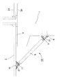
図1は、本発明の一実施形態である桁落下防止構造の構成を示した要部説明図である。
図1に示すように、この桁落下防止構造101は、橋脚1と桁2との間をつなぐように設けられる。桁2は、支承部材3を介して橋脚1上に支持されている。また、桁2には、桁2Aが隣接・連続しており、桁2Aは、支承部材3Aを介して橋脚1上に支持されている。
【0023】
また、この桁落下防止構造101は、橋脚1の上端部付近に側面等に固定された定着部材8と、桁2の端部付近の下面等に固定された定着部材10と、これらの間に配置された緩衝部材5と、緩衝部材5の一端と定着部材8とを連結する連結部材9と、緩衝部材5の他端と定着部材10とを連結する連結部材11を備えて構成されている。
【0024】
次に、以下に、上記した緩衝部材5のさらに詳細な構成について、図2を参照しつつ説明する。図2に示すように、この緩衝部材5は、略丸棒状に形成されており、複数のリング6,6,…の周囲に、ゴムや合成樹脂等の弾性体7を略円柱状に充填して形成されている。各リング6,6,…の各々は、互いに接触しないように所定の間隙を配して配列され、相互に嵌合し、チェーンを形成している。また、これら複数のリング6,6,…の全体は、直線状に整列されている。
【0025】
なお、図2においては、リング6としては長円状の環が図示されているが、円状や楕円状、略「ロ」字状でもよく、略「θ」字状や略「日」字状の部材のように中間に結合部材が取り付けられてもよく、一般に線の両端が閉じた閉合体であればよい。
【0026】
上記の緩衝部材5は、例えば、リング6,6,…を上記の状態で金型(図示せず)等の中に配置し、各リング6,6,…の周囲に弾性体となるべき未固化の原料を流し込み、固化させることにより形成される。弾性体7がゴムの場合には、さらに金型(図示せず)内において加熱する加硫工程等を施す。
【0027】
この緩衝部材5においては、各リング6,6,…が弾性体7内に埋設されるとともに、各リング間の間隙にも弾性体7が充填される。また、緩衝部材5の両端には、端部のリング60,60の一部が弾性体7の外部に露出しており、この部分が略環状をなし、他の部材と連結可能になっている。あるいは、緩衝部材5の両端のリングに別の取付金具(図示せず)を嵌合させておき、この取付金具(図示せず)の一部が弾性体7の外部に露出させるようにしてもよい。
【0028】
このように構成されることにより、緩衝部材5の端リング60,60間に軸方向の引張力が作用すると、この引張力により緩衝部材5内に発生する引張応力は、緩衝部材5の内部の弾性体7を介して各リング6に伝達される。したがって、地震力のような衝撃的応力が加わっても、弾性体7により緩和・減衰された後に各リング6に伝達されるので、従来の裸の状態のチェーン4(図7)の場合とは異なり、破断することがない。
【0029】
次に、上記した連結部材と定着部材のさらに詳細な構成について、図3を参照しつつ説明する。図3は、例として、連結部材9と定着部材8の構成を示しているが、桁2と連結する側の連結部材11と定着部材10の構成も同様である。
図3に示すように、連結部材9は、例えば鋼鉄等の金属からなる金具であり、その一端(図上の左端)には、接続具である緩衝ピン12Aが装着可能な円形孔21が設けられ、この円形孔21に緩衝ピン12Aが挿入され装着されている。
【0030】
また、緩衝ピン12Aの軸部13Aには、後述する衝撃緩和部14Aが設けられており、この衝撃緩和部14Aの周囲は空間22となっており、この空間22内で緩衝部材5の端部の端リング60が緩衝ピン12Aの衝撃緩和部14Aに嵌合し装着されるようになっている。このため、緩衝部材5は、軸部13Aのまわりに回動可能となっている。
【0031】
また、連結部材9の他端(図上の右端)には円盤の一部をなす形状に形成された第1ヒンジ片23が設けられており、この第1ヒンジ片23にヒンジピン17が挿入可能な円形孔が設けられている。
一方、定着部材8は、例えば鋼鉄等の金属からなる金具であり、平板状部材31の略中央に、円盤の一部をなす形状に形成された2つの第2ヒンジ片32,32(一方のみ図示)が平板状部材31の面上で互いに離間されて垂直に立設されている。また、2つ第2ヒンジ片32,32にはヒンジピン17が挿入可能な円形孔が設けられている。
【0032】
そして、2つの第2ヒンジ片32,32の間のスリット空間(図示せず)内に、第1ヒンジ片23が挿入されて各円形孔が連通するように整合され、円形孔内に丸棒状のヒンジピン17が挿入された後、ヒンジピン17の両端が円形孔から抜け出さないように拡径処理されている。このため、連結部材9は、ヒンジピン17のまわりに回動可能となっている。
【0033】
また、定着部材8の平面状部材31には、第2ヒンジ片32をはさんで両側には、それぞれ固定具である緩衝ボルト12が挿入可能な円形孔33が設けられている。また、これらの円形孔33,33に連通するようにして、橋脚1にボルト孔34,34が設けられている。ボルト孔34の内周面には、雌ネジが形成されている。この円形孔33には、それぞれ緩衝ボルト12が挿入され、緩衝ボルト12の軸部13の根元側に設けられた後述する衝撃緩和部14が円形孔33の内壁と対向し、緩衝ボルト12の軸部の先端側外周面に形成された雄ネジがボルト孔34の内周面の雌ネジと螺合することにより、定着部材8が橋脚1に固定されるようになっている。
【0034】
次に、上記した緩衝ボルト12と緩衝ピン12Aのさらに詳細な構成について、図5を参照しつつ説明する。
図5(A)に示すように、緩衝ボルト12は、軸部13と、衝撃緩和部14と、押え板15を有して構成されている。衝撃緩和部14は、六角形状の頭部から延びる軸部13の根元側(六角形状頭部側)の周囲に設けられており、弾力材と布材とが交互に積層された形成されている。弾力材としては、ゴムや合成樹脂等からなる帯状材が用いられ、布材としては天然繊維又は合成繊維等からなる織布又は不織布等が用いられる。押え板15は、ボルトの六角形状の頭部と衝撃緩和部14との間に配置されている。また、軸部13の先端部(六角形状頭部の反対側の端部)の外周面には、上述したように雄ネジが形成されている。
【0035】
上記の衝撃緩和部14は、例えば、上記の帯状材の裏面又は表面に同一形状の布材を当接し、弾力材と布材の2層からなる帯状材とし、軸部13の周囲に巻回し、接着又は加熱溶着等により略円筒状に成形する。弾力材がゴムの場合には、さらに金型(図示せず)内において加熱する加硫工程等を施す。
【0036】
また、図5(B)に示すように、緩衝ピン12Aは、円盤状のフランジ部から延びる軸部13Aと、衝撃緩和部14Aと、キャップ16を有して構成されている。衝撃緩和部14Aは、軸部13Aの根元側(円盤状フランジ側)の周囲に設けられており、その構成は、上記した緩衝ボルト12の衝撃緩和部14とまったく同様である。
【0037】
上記の軸部13Aの先端部(円盤状フランジ部の反対側の端部)には雌ネジ孔25が形成されている。また、キャップ16は、円盤状のフランジ部から延びる軸部を有しており、このキャップ16の軸部の外周面には、雌ネジ孔25と螺合可能な雄ネジが形成されている。
【0038】
したがって、図3に示す連結部材9の円形孔21に緩衝ピン12Aを装着する場合には、例えば、図3において円形孔21の右上方から緩衝ピン12Aの衝撃緩和部13Aの部分を挿入し、図3において円形孔21の左下方にのぞく雌ネジ孔25にキャップ16を螺着させることにより、緩衝ピン12Aが円形孔21から抜け出さないように装着することができる。
【0039】
図4は、図1に示す桁落下防止構造における連結部材と定着部材の他の構成例を示す図である。図4は、例として、他の連結部材9Aと定着部材8Aの構成を示しているが、桁2と連結する側の連結部材と定着部材の構成も同様である。
図4に示すように、連結部材9Aは、例えば鋼鉄等の金属からなる金具であり、平板状部材の一側に抜出防止部35が垂直に(図の下方に)立設され、平板状部材には、上記した緩衝ボルト12の衝撃緩和部14が挿入可能な円形孔36が設けられている。また、抜出防止部35を設けるかわりに、平板状部材を、緩衝部材5の端リング60又は取付金具(図示せず)の平面投影面(定着部材方向への投影面)よりも大きな形状としてもよい。
【0040】
また、定着部材8Aは、例えば鋼鉄等の金属からなる金具であり、ブロック状部材に、上記した緩衝ボルト12の軸部13の先端付近が挿入可能な円形孔37が設けられている。
また、円形孔37に連通するようにして、橋脚1にボルト孔38が設けられている。ボルト孔38の内周面には、雌ネジが形成されている。上記の円形孔により緩衝ボルト12が挿入可能となっており、緩衝ボルト12の軸部13の衝撃緩和部14に、緩衝部材5の端リング60が嵌合し装着されるようになっている。また、緩衝ボルト12の軸部の先端側外周面に形成された雄ネジがボルト孔38の内周面の雌ネジと螺合することにより、定着部材8Aが橋脚1に固定されるようになっている。このように構成しても、緩衝部材5を桁2や橋脚1に定着することができる。
【0041】
この場合、緩衝部材5は、緩衝ボルト12の軸部13のまわりに回動可能となっている。また、連結部材9Aには、抜出防止部35が設けられたり、連結部材9Aの平板状部材の投影面が、緩衝部材5の端リング60又は取付金具(図示せず)よりも大きく設定されているので、緩衝部材5の端リング60又は取付金具(図示せず)と緩衝ボルト12との嵌合が外れることはない。
【0042】
図4に示す定着方式においては、緩衝ボルト12を、緩衝部材5と連結部材9Aとを接続する接続具と、連結部材9Aを定着部材8Aに固定する固定具とを兼用させるようにして用いることができる。あるいは、図4に示した定着部材8Aを他の別のアンカーボルト等により橋脚1や桁2に固定しておき、緩衝ボルト12を接続具としてのみ使用してもよい。あるいはまた、定着部材8Aを橋脚1や桁2と別体の部材とせず、橋脚1や桁2の一部、例えば突起部として形成してもよい。
【0043】
上記のような構成により、橋脚1が図の上下方向又は左右方向に振動し、定着部材8又は8Aと緩衝ボルト12との間のせん断力や、緩衝ボルト12の引抜力等が作用しても、これらの力は、緩衝ボルト12の衝撃緩和部14により緩和され、緩衝部材5に軸方向の減衰した引張力として伝達される。
逆に、緩衝部材5側から橋脚1側へ向う引張力は、緩衝ボルト12の衝撃緩和部14により緩和され、減衰したせん断力やボルトの引抜力等として橋脚1側へ伝達される。
【0044】
同様にして、図1において、桁2が図の上下方向又は左右方向に振動し、定着部材10とその固定用の緩衝ボルト12との間のせん断力や、緩衝ボルト12の引抜力等が作用しても、これらの力は、固定用の緩衝ボルト12の衝撃緩和部14により緩和され、緩衝部材5に減衰した引張力として伝達される。
逆に、緩衝部材5側から桁2側へ向う引張力は、緩衝ボルト12の衝撃緩和部14により緩和され、減衰したせん断力やボルトの引抜力等として桁2側へ伝達される。
【0045】
一方、連結部材9,9A又は11と、緩衝部材5との間には、緩衝ピン12Aの衝撃緩和部14A又は緩衝ボルト12の衝撃緩和部14が介在するため、この部分により、緩衝部材5へ向う力、あるいは緩衝部材5からの力は、緩和・減衰されて伝達される。
また、上記したように、緩衝部材5に伝達された力は、弾性体7により緩和・減衰される。
【0046】
したがって、この桁落下防止構造101に地震力のような衝撃的応力が加わっても、衝撃緩和部14Aあるいは14の弾力材により、さらには緩衝部材5内の弾性体7により緩和・減衰されるので、従来の裸の状態のチェーン4(図7)の場合とは異なり、緩衝部材5の端リング60,緩衝ピン12A,連結部材9又は11,ヒンジピン17,定着部材8又は10,緩衝ボルト12などが損傷又は破断することはない。
また、緩衝部材5が弾性を有するため、桁落下防止構造の設置時の公差に追随可能である、という利点もある。
【0047】
本発明は、他の実施形態としても実施可能である。
例えば、図6に示すように構成してもよい。図6に示すように、この桁落下防止構造102は、図1に示す桁落下防止構造101の橋脚側の連結部材9と定着部材8との間に、複数のリング6Aからなるチェーン4を介在させたものである。
【0048】
このように介在部材を配置すると、桁落下防止構造の設置長さが緩衝部材5の長さよりもかなり長い場合などに、チェーン4によって長さ調整を行うことが可能となる。
介在部材としては、他の構成のものも使用可能であり、鋼棒や細長い鋼材等であってもよい。また、上記の鋼棒等の両端にネジを形成して両端を螺合により連結部材と定着部材に取り付けることもできる。
【0049】
また、この変形として、いわゆる「ターンバックル」状の部材を介在部材としてもよい。ターンバックルのような部材を用いれば、回動することにより介在部材の部材長を増減調整することが可能となる。
【0050】
また、介在部材は、図6に示すように、桁落下防止構造の橋脚側の連結部材と定着部材との間に設けるだけでなく、桁落下防止構造の桁側の連結部材と定着部材との間に設けてもよく、また、橋脚側及び桁側の双方に設けてもよい。
【0051】
さらに他の実施形態として、図示はしないが、隣接する桁2Aと桁2との間に上記と同様の構成の桁落下防止構造を配置してもよい。また、桁2と橋脚1との間と、隣接する桁2Aと桁2との間の双方に、上記と同様の構成の桁落下防止構造を配置してもよい。
【0052】
なお、上記した緩衝部材5が衝撃緩和機能を発揮し得る応力の上限値は、実験によれば、緩衝部材5内に埋設されるチェーンの材質には関係がなく、概ね緩衝部材5内に埋設されるチェーンの断面応力値でσc =250kg/cm2となっている。また、実験結果より、この緩衝部材5の引張耐力は、埋設されるチェーンの断面積の2倍にチェーンの断面応力値を乗じた値に等しくなっている。このため、緩衝部材5内に埋設されるチェーンの直径をdとすると、緩衝部材5の引張耐力Pは、下式
P=π・d2 ・σc /2
で与えられる。
【0053】
なお、本発明は、上記各実施形態に限定されるものではない。上記各実施形態は、例示であり、本発明の特許請求の範囲に記載された技術的思想と実質的に同一な構成を有し、同様な作用効果を奏するものは、いかなるものであっても本発明の技術的範囲に包含される。
【0054】
例えば、上記各実施形態においては、連結部材として、図3に示すような緩衝ピン12A、あるいは図4に示すような緩衝ボルトを使用する例について説明したが、本発明はこれには限定されず、他の構造であってもよく、例えば、環状部材の組み合わせ、環状部材とピンとの組み合わせ、環状部材とフックとの組み合わせ、あるいは螺合による連結等であってもよく、機械的な連結であればどのようなものであってもよい。また、各嵌合部分に、上記した衝撃緩和部14又は14Aと同様の衝撃緩和部を設けるようにしてもよい。
【0055】
また、上記各実施形態においては、図3に示すように、緩衝ピン12Aの軸回りに回動可能でかつヒンジピン17の軸回りに回動可能な例、あるいは図4に示すように、緩衝ボルト12の軸回りに回動可能な例などについて説明したが、本発明はこれには限定されず、図3において、さらに緩衝部材5の軸回りに回動可能に構成してもよい。このように構成すると、3次元のいずれの方向の回動も可能となり、地震力等により桁落下防止構造にねじれ力が作用した場合でも、各部に悪影響や損傷等を与えることがない。
【0056】
【発明の効果】
以上説明したように、本発明によれば、複数の閉合体(6)の各々が接触しないように間隙を配して相互に嵌合させるとともに閉合体(6)の全体を直線状に整列させた状態で各閉合体(6)を弾性体(7)内に埋設しかつ間隙にも弾性体(7)を充填することにより略棒状に形成した緩衝部材(5)の一端部(60)を桁(2)の端部付近に定着させ、桁(2)を支持する桁支持構造物(1)の上部付近に緩衝部材(5)の他端部(60)を定着させ、緩衝部材(5)の端部と桁支持構造物(1)の上部付近との間に、チェーン(4)を設けるようにするか、あるいは、複数の閉合体(6)の各々が接触しないように間隙を配して相互に嵌合させるとともに閉合体(6)の全体を直線状に整列させた状態で各閉合体(6)を弾性体(7)内に埋設しかつ間隙にも弾性体(7)を充填することにより略棒状に形成した緩衝部材(5)の一端部(60)を桁(2)の端部付近に定着させ、桁(2)に隣接する他の桁である隣接桁(2A)の端部付近に緩衝部材(5)の他端部(60)を定着させ、緩衝部材(5)の端部と桁(2)の端部付近との間に、チェーン(4)を設けるようにしたので、地震力のような衝撃的外力が加わっても、緩衝部材により緩和・減衰され、つねに良好な桁落下防止機能を果たすことができる。
また、緩衝部材(5)が弾性を有するため、桁落下防止構造の設置時の公差に対応可能である、という利点もある。
【図面の簡単な説明】
【図1】 本発明の一実施形態である桁落下防止構造の構成を示す要部説明図である。
【図2】 図1に示す桁落下防止構造における緩衝部材の構成を示す一部欠截斜視図である。
【図3】 図1に示す桁落下防止構造における連結部材と定着部材の一構成例を示す図である。
【図4】 図1に示す桁落下防止構造における連結部材と定着部材の他の構成例を示す図である。
【図5】 図1及び図2に示す桁落下防止構造に用いる固定具又は接続具の構成例を示す図であり、図5(A)はボルトとして構成した例を、図5(B)はピンとして構成した例を、それぞれ示している。
【図6】 本発明の他の実施形態である桁落下防止構造の構成を示す要部説明図である。
【図7】 従来の桁落下防止構造の構成を示す要部説明図である。
【符号の説明】
1 橋脚
2,2A 桁
3 支承部材
4 チェーン
5 緩衝部材
6,6A リング
7 弾性体
8,8A,10 定着部材
9,9A,11 連結部材
12 緩衝ボルト
12A 緩衝ピン
13,13A 軸部
14,14A 衝撃緩和部
15 押え板
16 キャップ
25 ネジ孔
17 ヒンジピン
21 円形孔
22 空間
23 第1ヒンジ片
31 平板状部材
32 第2ヒンジ片
33 円形孔
34 ボルト孔
35 抜出防止部
36,37 円形孔
38 ボルト孔
60 端リング
101,102,200 桁落下防止構造[0001]
BACKGROUND OF THE INVENTION
The present invention relates to a girder falling prevention structure provided between a girder used for a railway or a road and a girder support structure such as a pier or an abutment or between successive girder.
[0002]
[Prior art]
Conventionally, this type of girder dropping prevention structure has been configured as shown in the explanatory view of the main part in FIG. As shown in FIG. 7, this girder
[0003]
The girder
[0004]
Further, the above-described chain 4B cannot cope with the expansion and contraction of the
[0005]
[Problems to be solved by the invention]
However, the conventional girder
[0006]
Further, as described above, the chain 4B connecting the
[0007]
Further, due to the large vibration as described above, even if the chain 4B itself does not break, the bolts of the
[0008]
The present invention has been made to solve the above-mentioned problems, and the problem to be solved by the present invention is to prevent a girder falling that can sufficiently ensure a girder falling prevention function even when an impact force such as seismic force is applied. To provide a structure.
[0009]
[Means for Solving the Invention]
In order to solve the above-described problem, the girder dropping prevention structure according to claim 1 of the present invention is arranged so that each of the plurality of closing bodies (6) is fitted with a gap so as not to contact each other, and the closing body ( 6) Each of the closed bodies (6) is embedded in an elastic body (7) in a state where the whole is linearly aligned, and the gap is filled with the elastic body (7) to form a substantially rod shape. One end (60) of the buffer member (5) is fixed near the end of the beam (2), and the buffer member (5) is near the upper portion of the beam support structure (1) for supporting the beam (2). Fix the other end (60) of A chain (4) is provided between the end of the buffer member (5) and the vicinity of the upper part of the girder support structure (1). It is characterized by that.
[0010]
Moreover, the girder dropping prevention structure according to
[0011]
The girder drop prevention structure according to
[0012]
The girder drop prevention structure according to claim 4 of the present invention is the girder drop prevention structure according to
[0013]
The girder drop prevention structure according to claim 5 of the present invention is the girder drop prevention structure according to claim 1, wherein the fixing member (10) is a metal fitting in the vicinity of the end of the girder (2). Is fixed by a buffer bolt (12), and the buffer bolt (12) has an impact relaxation portion (14) in which elastic materials and cloth materials are alternately laminated around the shaft portion (13). Features.
[0014]
The girder drop prevention structure according to
[0015]
A girder drop prevention structure according to
[0016]
The girder drop prevention structure according to claim 8 of the present invention is the girder drop prevention structure according to claim 4, wherein the planar member of the fixing member (8) fixed near the end of the adjacent girder (2A). On the second hinge piece (32, 32) erected on the surface of (31), the first hinge piece (23) which is one end of the connecting member (9) which is a metal fitting is a hinge pin (17). The other end of the connecting member (9) is provided with a circular hole (21) and a space (22) therein, and a buffer pin (12A) is provided in the circular hole (21). The buffer pin (12A) has an impact relaxation portion (14A) in which elastic material and cloth material are alternately laminated around the shaft portion (13A), and the shock pin (12A) has the impact relaxation portion (14A) in the space (22). The end portion (60) of the buffer member (5) is attached to the impact relaxation portion (14A) of the buffer pin (12A). Combined, characterized in that it is mounted.
[0017]
The girder drop prevention structure according to claim 9 of the present invention is the girder drop prevention structure according to claim 5, wherein the fixing member (10) is a planar member (10) fixed in the vicinity of the end of the girder (2). The first hinge piece (23), which is one end of the connecting member (11), which is a metal fitting, is provided on the second hinge piece (32, 32) erected on the surface of 31) by the hinge pin (17). A circular hole (21) and an internal space (22) are provided at the other end of the connecting member (9), and a buffer pin (12A) is provided in the circular hole (21). The inserted buffer pin (12A) has an impact buffering portion (14A) in which elastic material and cloth material are alternately stacked around the shaft portion (13A), and the buffer pin (12A) has the shock absorbing portion in the space (22). The end portion (60) of the cushioning member (5) is fitted into the impact relaxation portion (14A) of the pin (12A). And characterized in that it is mounted.
[0018]
A girder drop prevention structure according to claim 10 of the present invention is the girder drop prevention structure according to
[0019]
The girder drop prevention structure according to claim 11 of the present invention is the girder drop prevention structure according to claim 1, wherein the end of the buffer member (5) is located near the upper part of the girder support structure (1). The fixing member (8), which is a metal fitting made of a fixed metal, is fixed so as to be rotatable about the axis of the buffer member (5).
[0020]
A girder drop prevention structure according to claim 12 of the present invention is the girder drop prevention structure according to
[0021]
DETAILED DESCRIPTION OF THE INVENTION
Hereinafter, embodiments of the present invention will be described in detail with reference to the drawings.
[0022]
FIG. 1 is an explanatory view of a main part showing a configuration of a girder dropping prevention structure according to an embodiment of the present invention.
As shown in FIG. 1, the girder
[0023]
The girder dropping
[0024]
Next, a more detailed configuration of the buffer member 5 described above will be described with reference to FIG. As shown in FIG. 2, the buffer member 5 is formed in a substantially round bar shape, and an
[0025]
In FIG. 2, an oval ring is illustrated as the
[0026]
For example, the buffer member 5 is configured such that the
[0027]
In the buffer member 5, the
[0028]
With this configuration, when an axial tensile force acts between the end rings 60, 60 of the buffer member 5, the tensile stress generated in the buffer member 5 by this tensile force is generated inside the buffer member 5. It is transmitted to each
[0029]
Next, a more detailed configuration of the connecting member and the fixing member will be described with reference to FIG. FIG. 3 shows the configuration of the connecting member 9 and the fixing member 8 as an example, but the configuration of the connecting member 11 and the fixing
As shown in FIG. 3, the connecting member 9 is a metal fitting made of metal such as steel, and a
[0030]
Further, an
[0031]
Further, the other end (right end in the figure) of the connecting member 9 is provided with a
On the other hand, the fixing member 8 is a metal fitting made of a metal such as steel, and has two
[0032]
The
[0033]
In addition, the
[0034]
Next, a more detailed configuration of the
As shown in FIG. 5A, the
[0035]
For example, the
[0036]
Further, as shown in FIG. 5B, the
[0037]
A
[0038]
Therefore, when attaching the
[0039]
FIG. 4 is a view showing another configuration example of the connecting member and the fixing member in the girder dropping prevention structure shown in FIG. FIG. 4 shows the configuration of another connecting
As shown in FIG. 4, the connecting member 9 </ b> A is a metal fitting made of a metal such as steel, for example, and an
[0040]
The fixing member 8A is a metal fitting made of a metal such as steel, and a
A
[0041]
In this case, the buffer member 5 is rotatable around the
[0042]
In the fixing method shown in FIG. 4, the
[0043]
Even if the bridge pier 1 vibrates in the vertical direction or the horizontal direction in the figure and the shearing force between the fixing member 8 or 8A and the
Conversely, the tensile force from the buffer member 5 side toward the pier 1 side is relaxed by the
[0044]
Similarly, in FIG. 1, the
On the contrary, the tensile force from the buffer member 5 side toward the
[0045]
On the other hand, between the connecting member 9, 9 </ b> A or 11 and the buffer member 5, the
Further, as described above, the force transmitted to the buffer member 5 is relaxed and attenuated by the
[0046]
Therefore, even if impact stress such as seismic force is applied to the girder
Moreover, since the buffer member 5 has elasticity, there is also an advantage that the tolerance at the time of installation of the girder dropping prevention structure can be followed.
[0047]
The present invention can be implemented as other embodiments.
For example, you may comprise as shown in FIG. As shown in FIG. 6, this girder
[0048]
When the interposition member is arranged in this way, the length can be adjusted by the chain 4 when the installation length of the girder dropping prevention structure is considerably longer than the length of the buffer member 5 or the like.
As the interposition member, those having other configurations can be used, and may be a steel bar, an elongated steel material, or the like. It is also possible to form screws at both ends of the steel rod or the like and attach both ends to the connecting member and the fixing member by screwing.
[0049]
In addition, as a modification, a so-called “turn buckle” -shaped member may be used as the interposed member. If a member such as a turnbuckle is used, the length of the interposed member can be increased or decreased by rotating.
[0050]
Further, as shown in FIG. 6, the interposition member is not only provided between the connecting member on the pier side of the girder fall prevention structure and the fixing member, but also between the connecting member on the girder fall prevention structure and the fixing member. It may be provided between them, or may be provided on both the pier side and the girder side.
[0051]
As yet another embodiment, although not shown, a girder dropping prevention structure having the same configuration as described above may be disposed between the
[0052]
Note that the upper limit value of the stress at which the buffer member 5 described above can exert an impact mitigating function is not related to the material of the chain embedded in the buffer member 5 according to experiments, and is generally embedded in the buffer member 5. The cross-sectional stress value of the chain is σc = 250 kg /
P = π ·
Given in.
[0053]
The present invention is not limited to the above embodiments. Each of the embodiments described above is an exemplification, and any configuration that has substantially the same configuration as the technical idea described in the claims of the present invention and has the same operational effects can be used. It is included in the technical scope of the present invention.
[0054]
For example, in each of the above embodiments, the example in which the
[0055]
Further, in each of the above-described embodiments, as shown in FIG. 3, an example that can rotate around the axis of the
[0056]
【The invention's effect】
As described above, according to the present invention, a gap is arranged so that each of the plurality of closing bodies (6) does not come into contact with each other, and the entire closing body (6) is aligned linearly. One end portion (60) of the buffer member (5) formed in a substantially rod shape by embedding each closed body (6) in the elastic body (7) in a state of being closed and filling the gap with the elastic body (7). Fix near the end of the beam (2), and fix the other end (60) of the buffer member (5) near the top of the beam support structure (1) that supports the beam (2). A chain (4) is provided between the end of the buffer member (5) and the vicinity of the upper part of the girder support structure (1). Alternatively, each of the plurality of closed bodies (6) may be fitted to each other with a gap so that each of the closed bodies (6) does not come into contact with each other, and the entire closed body (6) is aligned in a straight line. One end (60) of the buffer member (5) formed in a substantially rod shape by embedding the closed body (6) in the elastic body (7) and filling the gap with the elastic body (7) is used as the girder (2). The other end (60) of the buffer member (5) is fixed near the end of the adjacent beam (2A), which is another beam adjacent to the beam (2). A chain (4) is provided between the end of the buffer member (5) and the vicinity of the end of the beam (2). As a result, even if an impact external force such as seismic force is applied, it is relaxed and attenuated by the buffer member, and a good girder fall prevention function can always be achieved.
Moreover, since the buffer member (5) has elasticity, there is also an advantage that it is possible to cope with a tolerance at the time of installation of the girder dropping prevention structure.
[Brief description of the drawings]
FIG. 1 is a main part explanatory view showing a configuration of a girder drop prevention structure according to an embodiment of the present invention.
FIG. 2 is a partially broken perspective view showing a configuration of a buffer member in the girder dropping prevention structure shown in FIG. 1;
FIG. 3 is a view showing a configuration example of a connecting member and a fixing member in the girder dropping prevention structure shown in FIG. 1;
4 is a view showing another configuration example of a connecting member and a fixing member in the girder dropping prevention structure shown in FIG. 1. FIG.
5A and 5B are diagrams showing a configuration example of a fixture or connection tool used in the girder dropping prevention structure shown in FIGS. 1 and 2, FIG. 5A is an example configured as a bolt, and FIG. Each example is configured as a pin.
FIG. 6 is a main part explanatory view showing a configuration of a girder drop prevention structure according to another embodiment of the present invention.
FIG. 7 is a main part explanatory view showing a configuration of a conventional girder dropping prevention structure.
[Explanation of symbols]
1 Pier
2,2A digits
3 Bearing members
4 Chain
5 cushioning member
6,6A ring
7 Elastic body
8, 8A, 10 Fixing member
9, 9A, 11 connecting member
12 Buffer bolt
12A Buffer pin
13, 13A Shaft
14, 14A Impact mitigation part
15 Presser plate
16 cap
25 Screw holes
17 Hinge pin
21 circular holes
22 space
23 First hinge piece
31 Flat member
32 Second hinge piece
33 circular holes
34 Bolt hole
35 Extraction prevention part
36, 37 round holes
38 bolt holes
60 end ring
101, 102, 200 girder fall prevention structure
Claims (12)
Priority Applications (1)
| Application Number | Priority Date | Filing Date | Title |
|---|---|---|---|
| JP08205196A JP3756979B2 (en) | 1996-03-11 | 1996-03-11 | Girder fall prevention structure |
Applications Claiming Priority (1)
| Application Number | Priority Date | Filing Date | Title |
|---|---|---|---|
| JP08205196A JP3756979B2 (en) | 1996-03-11 | 1996-03-11 | Girder fall prevention structure |
Publications (2)
| Publication Number | Publication Date |
|---|---|
| JPH09242019A JPH09242019A (en) | 1997-09-16 |
| JP3756979B2 true JP3756979B2 (en) | 2006-03-22 |
Family
ID=13763722
Family Applications (1)
| Application Number | Title | Priority Date | Filing Date |
|---|---|---|---|
| JP08205196A Expired - Lifetime JP3756979B2 (en) | 1996-03-11 | 1996-03-11 | Girder fall prevention structure |
Country Status (1)
| Country | Link |
|---|---|
| JP (1) | JP3756979B2 (en) |
Cited By (1)
| Publication number | Priority date | Publication date | Assignee | Title |
|---|---|---|---|---|
| JP2010053618A (en) * | 2008-08-29 | 2010-03-11 | Kawakin Core-Tech Co Ltd | Device for preventing bridge fall |
Families Citing this family (13)
| Publication number | Priority date | Publication date | Assignee | Title |
|---|---|---|---|---|
| JP4744307B2 (en) * | 2006-01-19 | 2011-08-10 | 濱中ナット株式会社 | Mechanical property imparting structure |
| JP4794309B2 (en) * | 2006-02-06 | 2011-10-19 | 株式会社エスイー | Structure coupling device |
| JP4827612B2 (en) * | 2006-05-24 | 2011-11-30 | 中日本高速道路株式会社 | Stretched gap covering structure for wall rail |
| JP4766429B2 (en) * | 2006-10-23 | 2011-09-07 | 株式会社駒井ハルテック | Method for drilling mounting holes for bracket fittings in fallen bridge prevention device |
| JP5443323B2 (en) * | 2010-11-16 | 2014-03-19 | 三井造船株式会社 | Floating pier |
| JP5689699B2 (en) * | 2011-01-28 | 2015-03-25 | 悟 川上 | Fall bridge prevention device |
| JP5638981B2 (en) * | 2011-02-25 | 2014-12-10 | 株式会社横河ブリッジ | Fall-bridge prevention device and fall-bridge prevention structure |
| CN103306193B (en) * | 2013-06-15 | 2015-02-25 | 中南大学 | Vertical beam falling-off prevention system |
| JP6298668B2 (en) * | 2014-03-18 | 2018-03-20 | ショーボンド建設株式会社 | Bridge girder fall prevention device |
| CN104499422B (en) * | 2014-11-24 | 2016-09-14 | 北京工业大学 | A kind of friction energy-dissipating anti-fall girder apparatus |
| JP2020158959A (en) * | 2019-03-25 | 2020-10-01 | シバタ工業株式会社 | Cover body and manufacturing method of cover body |
| CN110965456B (en) * | 2019-12-20 | 2021-06-25 | 中国地震局工程力学研究所 | Synchronous limiting and beam falling preventing device based on energy dissipation type structure |
| CN112815152B (en) * | 2021-01-23 | 2022-07-22 | 浙江亿火建筑科技有限公司 | Drainage combination one-way antidetonation support |
-
1996
- 1996-03-11 JP JP08205196A patent/JP3756979B2/en not_active Expired - Lifetime
Cited By (1)
| Publication number | Priority date | Publication date | Assignee | Title |
|---|---|---|---|---|
| JP2010053618A (en) * | 2008-08-29 | 2010-03-11 | Kawakin Core-Tech Co Ltd | Device for preventing bridge fall |
Also Published As
| Publication number | Publication date |
|---|---|
| JPH09242019A (en) | 1997-09-16 |
Similar Documents
| Publication | Publication Date | Title |
|---|---|---|
| JP3756979B2 (en) | Girder fall prevention structure | |
| US8215607B2 (en) | Damping device of stay cable | |
| JP2944217B2 (en) | Vibration suppression coupling device for earthquake resistance of structures | |
| US4514942A (en) | Damping installation for earthquake-endangered buildings | |
| US4166344A (en) | Earthquake guarding system | |
| KR20010000649A (en) | Apparatus for preveting separating super structure from continous steel box bridge and construction work method there of | |
| JP3871393B2 (en) | Insulating support device and seismic isolation structure using this support device | |
| KR102198672B1 (en) | Distribution panel with earthquake-proof function | |
| JPH1096337A (en) | Cylinder type disc lead damper | |
| JP3699944B2 (en) | Protective device for falling rocks and net for the device | |
| JP5925514B2 (en) | Laminated rubber structure | |
| KR102174473B1 (en) | Earthquake-proof expansion joint | |
| WO2017103729A1 (en) | Anti-seismic connection joint | |
| JPH11131426A (en) | Bridge falling preventing device | |
| JP4483151B2 (en) | Vertical seismic isolation device | |
| JP3699943B2 (en) | Protective device for falling rocks and net for the device | |
| JP3757237B2 (en) | Structure coupling device | |
| KR100319957B1 (en) | Elastic support for absorbing pulse and preventing removement of slab | |
| KR100387949B1 (en) | Apparatus for prevetion falling from upper structure of steel box bridge on simple support and its construction work method | |
| JP7121543B2 (en) | Fall prevention device for side blocks in bridge bearings | |
| JP2002322654A (en) | Structure of pile head joint part | |
| JP2604159Y2 (en) | Bridge. Structure fall prevention device | |
| JP2886163B2 (en) | Vibration and shock isolation and energy absorber | |
| JP2000129629A (en) | Steel damper device | |
| JPS61189342A (en) | Damper |
Legal Events
| Date | Code | Title | Description |
|---|---|---|---|
| A977 | Report on retrieval |
Free format text: JAPANESE INTERMEDIATE CODE: A971007 Effective date: 20050120 |
|
| A131 | Notification of reasons for refusal |
Free format text: JAPANESE INTERMEDIATE CODE: A131 Effective date: 20050201 |
|
| A521 | Written amendment |
Free format text: JAPANESE INTERMEDIATE CODE: A523 Effective date: 20050329 |
|
| A131 | Notification of reasons for refusal |
Free format text: JAPANESE INTERMEDIATE CODE: A131 Effective date: 20050913 |
|
| A521 | Written amendment |
Free format text: JAPANESE INTERMEDIATE CODE: A523 Effective date: 20051108 |
|
| TRDD | Decision of grant or rejection written | ||
| A01 | Written decision to grant a patent or to grant a registration (utility model) |
Free format text: JAPANESE INTERMEDIATE CODE: A01 Effective date: 20051206 |
|
| A61 | First payment of annual fees (during grant procedure) |
Free format text: JAPANESE INTERMEDIATE CODE: A61 Effective date: 20051226 |
|
| R150 | Certificate of patent or registration of utility model |
Free format text: JAPANESE INTERMEDIATE CODE: R150 |
|
| S111 | Request for change of ownership or part of ownership |
Free format text: JAPANESE INTERMEDIATE CODE: R313118 |
|
| R350 | Written notification of registration of transfer |
Free format text: JAPANESE INTERMEDIATE CODE: R350 |
|
| FPAY | Renewal fee payment (event date is renewal date of database) |
Free format text: PAYMENT UNTIL: 20100106 Year of fee payment: 4 |
|
| FPAY | Renewal fee payment (event date is renewal date of database) |
Free format text: PAYMENT UNTIL: 20100106 Year of fee payment: 4 |
|
| S111 | Request for change of ownership or part of ownership |
Free format text: JAPANESE INTERMEDIATE CODE: R313118 |
|
| FPAY | Renewal fee payment (event date is renewal date of database) |
Free format text: PAYMENT UNTIL: 20100106 Year of fee payment: 4 |
|
| R350 | Written notification of registration of transfer |
Free format text: JAPANESE INTERMEDIATE CODE: R350 |
|
| S111 | Request for change of ownership or part of ownership |
Free format text: JAPANESE INTERMEDIATE CODE: R313117 |
|
| FPAY | Renewal fee payment (event date is renewal date of database) |
Free format text: PAYMENT UNTIL: 20110106 Year of fee payment: 5 |
|
| FPAY | Renewal fee payment (event date is renewal date of database) |
Free format text: PAYMENT UNTIL: 20110106 Year of fee payment: 5 |
|
| R350 | Written notification of registration of transfer |
Free format text: JAPANESE INTERMEDIATE CODE: R350 |
|
| FPAY | Renewal fee payment (event date is renewal date of database) |
Free format text: PAYMENT UNTIL: 20120106 Year of fee payment: 6 |
|
| FPAY | Renewal fee payment (event date is renewal date of database) |
Free format text: PAYMENT UNTIL: 20120106 Year of fee payment: 6 |
|
| S533 | Written request for registration of change of name |
Free format text: JAPANESE INTERMEDIATE CODE: R313533 |
|
| FPAY | Renewal fee payment (event date is renewal date of database) |
Free format text: PAYMENT UNTIL: 20120106 Year of fee payment: 6 |
|
| R350 | Written notification of registration of transfer |
Free format text: JAPANESE INTERMEDIATE CODE: R350 |
|
| FPAY | Renewal fee payment (event date is renewal date of database) |
Free format text: PAYMENT UNTIL: 20130106 Year of fee payment: 7 |
|
| FPAY | Renewal fee payment (event date is renewal date of database) |
Free format text: PAYMENT UNTIL: 20130106 Year of fee payment: 7 |
|
| FPAY | Renewal fee payment (event date is renewal date of database) |
Free format text: PAYMENT UNTIL: 20140106 Year of fee payment: 8 |
|
| R250 | Receipt of annual fees |
Free format text: JAPANESE INTERMEDIATE CODE: R250 |
|
| R250 | Receipt of annual fees |
Free format text: JAPANESE INTERMEDIATE CODE: R250 |
|
| R250 | Receipt of annual fees |
Free format text: JAPANESE INTERMEDIATE CODE: R250 |
|
| EXPY | Cancellation because of completion of term |