JP3755966B2 - Pile joint structure - Google Patents
Pile joint structure Download PDFInfo
- Publication number
- JP3755966B2 JP3755966B2 JP20291997A JP20291997A JP3755966B2 JP 3755966 B2 JP3755966 B2 JP 3755966B2 JP 20291997 A JP20291997 A JP 20291997A JP 20291997 A JP20291997 A JP 20291997A JP 3755966 B2 JP3755966 B2 JP 3755966B2
- Authority
- JP
- Japan
- Prior art keywords
- pile
- fitting end
- end portion
- engaged
- joint
- Prior art date
- Legal status (The legal status is an assumption and is not a legal conclusion. Google has not performed a legal analysis and makes no representation as to the accuracy of the status listed.)
- Expired - Lifetime
Links
Images


Description
【0001】
【発明の属する技術分野】
本発明は、互いに嵌合自在な一対の外嵌端部と内嵌端部とを、軸芯方向に隣接する第1杭と第2杭とに各別に形成し、前記外嵌端部と前記内嵌端部とを嵌合させた状態で、軸芯周りの相対回動操作によって互いに抜止めすべく係合し合う係合部と被係合部とを、前記外嵌端部の内壁部と、前記内嵌端部の外壁部とに各別に設けてある杭の継手部構造に関する。
【0002】
【従来の技術】
従来、この種の杭の継手部構造としては、図7に示すごとくねじ式のものがあった。即ち、連接する一方の杭の端部には雄ねじ部30を形成し、他方の杭の端部には雌ねじ部31を形成しておく。例えば、このうち雌ねじ部31を形成した杭を先ず地中に埋設し、雄ねじ部30を形成した杭を前記埋設した杭に螺合させ、連結するのである。この螺合作業は、双方の杭の軸芯Z1,Z2どうしを一致させた状態で行う。
杭の継手部構造がねじ式であれば、杭の長手方向に沿った多数のねじ山が係合する。よって、連結が終了したのち杭に作用する曲げ力等に対して高い耐力を有することとなる。
【0003】
【発明が解決しようとする課題】
しかし、上記従来の杭の継手部構造においても次のような問題があった。
例えば、継手部に強い曲げ力が加わった場合には、図7(イ)に示すごとく、第1杭1の基端部9と第2杭2の先端部10とが、および、第1杭1の先端部10と第2杭2の基端部9とが離間する状態に継手部が変形する場合がある。当該変形が生じた場合には、杭に対する曲げ力は、第1杭1の外嵌端部4と第2杭2の内嵌端部6との間で未だ当接している部分に集中し、前記外嵌端部4と前記内嵌端部6との変形は益々増大して、第1杭1と第2杭2との連結が外れるおそれがある。
また、図7(ロ)に示すごとく、継手部に強い引張り力が加わった場合、或いは、図7(ハ)に示すごとく、継手部に強い圧縮力が加わった場合にも、やはり、基端部9と先端部10とが離間して、第1杭1と第2杭2とが抜け出し易い状態となる。これらは、係合部7と被係合部8との係合に抗って第1杭1と第2杭2とが離間・近接する結果、外嵌端部4は拡径し、内嵌端部6は縮径することに起因する。
このように、変形が生じ易い継手部は、十分な継手耐力を発揮することができず、未だ改善の余地があった。
本発明の目的は、このような従来技術の欠点を解消し、杭の継手部の変形を抑制して、高い曲げ耐力を備えた杭の継手部構造を提供することにある。
【0004】
【課題を解決するための手段】
(構成1)
本発明の杭の継手部構造は、請求項1に記載したごとく、係合した係合部と被係合部とが第1杭あるいは第2杭の径方向に離間するのを阻止するための離間阻止手段を、前記係 合部と前記被係合部とに設けてあるとともに、前記離間阻止手段を構成するのに、第1杭あるいは第2杭の縦断面視において、前記係合部および前記被係合部のうちの一方を、杭軸芯方向の幅が狭い幅狭部分と杭軸芯方向の幅が前記幅狭部分よりも幅広の幅広部分とが杭径方向に突出し、かつ、前記幅広部分が前記幅狭部分よりも突出方向先端側で突出している拡大突出部を有する形状とし、他方を前記拡大突出部が杭周方向から挿入可能で、かつ、前記拡大突出部の幅広部分を杭径方向に係合可能な幅狭の溝幅部分を備えた溝形状としてある点に特徴を有する。
(作用・効果)
本構成のごとく、係合した係合部と被係合部とを、第1杭あるいは第2杭の径方向に離間させないものとすれば、第1杭の外嵌端部と第2杭の内嵌端部との当接状態を良好に維持できる。例えば、杭の継手部に曲げ力が加わった場合でも、前記外嵌端部と前記内嵌端部との接当面積が変化しない。よって、外嵌端部および内嵌端部の断面形状等が変化するのを抑制することができる。この結果、高い曲げ耐力を有する継手部を得ることができる。
また、前記離間阻止手段を、前記係合部と前記被係合部とに設けてあるので、継手部に加わった曲げ力を外嵌端部と内嵌端部との全体で負担することができる。
【0005】
更に、前記離間阻止手段を構成するのに、第1杭あるいは第2杭の縦断面視において、前記係合部および前記被係合部のうちの一方を、杭軸芯方向の幅が狭い幅狭部分と杭軸芯方向の幅が前記幅狭部分よりも幅広の幅広部分とが杭径方向に突出し、かつ、前記幅広部分が前記幅狭部分よりも突出方向先端側で突出している拡大突出部を有する形状とし、他方を前記拡大突出部が杭周方向から挿入可能で、かつ、前記拡大突出部の幅広部分を杭径方向に係合可能な幅狭の溝幅部分を備えた溝形状としてあり、拡大突出部を有する係合部と溝状の被係合部とを係合させるものとしては、例えば、アリ溝構造のものが考えられる。この場合には、継手部に曲げ力が加わった場合は勿論のこと、引張り力あるいは圧縮力が加わった場合にも、外嵌端部と内嵌端部との離間を有効に阻止するから、あらゆる外力に対して高い耐力を発揮する継手部を構成することができる。
【0006】
(構成2)
本発明の杭の継手部構造は、請求項2に記載したごとく、前記外嵌端部の先端部に凸部を設けると共に、前記内嵌端部の基端部に、前記第1杭あるいは前記第2杭の軸芯方向から前記凸部に係合可能な基端溝部を設けて構成することができる。
(作用・効果)
一般的には、筒状体において断面変形が最も生じ易いのは開口端部である。つまり、開口端部は杭本体に比べて肉厚が薄く、また、基端部と比較して杭本体による変形拘束の程度が少ないからである。
しかし、本構成であれば、外嵌端部の先端部が、内嵌端部の基端部から離間するのを阻止するから、前記先端部の変形を有効に防止することができ、曲げ力等に対して高い耐力を発揮する継手部を得ることができる。
【0007】
(構成3)
本発明の杭の継手部構造は、請求項3に記載したごとく、前記内嵌端部の先端部に凸部を設けると共に、前記外嵌端部の基端部に、前記第1杭あるいは前記第2杭の軸芯方向から前記凸部に係合可能な基端溝部を設けて構成することができる。
(作用・効果)
一般的には、筒状体において断面変形が最も生じ易いのは開口端部である。つまり、開口端部は杭本体に比べて肉厚が薄く、また、基端部と比較して杭本体による変形拘束の程度が少ないからである。
しかし、本構成であれば、内嵌端部の先端部が、外嵌端部の基端部から離間するのを阻止するから、前記先端部の変形を有効に防止することができ、曲げ力等に対して高い耐力を発揮する継手部を得ることができる。
(構成4)
本発明の杭の継手部構造は、請求項4に記載したごとく、外嵌端部および内嵌端部の夫々の先端部に環状の凸部を設けると共に、前記外嵌端部および前記内嵌端部の夫々の基端部に、前記第1杭あるいは前記第2杭の軸芯方向から前記環状の凸部に係合可能な基端溝部を設けて構成することができる。
(作用・効果)
一般的には、筒状体において断面変形が最も生じ易いのは開口端部である。本構成の場合にも、第1杭の先端部および第2杭の先端部が、最も変形し易いと考えられる。つまり、これらの先端部は、第1杭の本体あるいは第2杭の本体に比べて肉厚が薄く、また、基端部と比較して杭本体による変形拘束の程度が少ないからである。
しかし、本構成であれば、例えば内嵌端部の先端部が、外嵌端部の基端部から離間するのを阻止するから、前記先端部の変形を有効に防止することができ、曲げ力等に対して高い耐力を発揮する継手部を得ることができる。
【0008】
(構成5)
本発明の杭の継手部構造は、請求項5に記載したごとく、前記内嵌端部に係る先端部の外周部と、前記外嵌端部に係る先端部の内周部とに面取り部を設けて構成することができる。
(作用・効果)
本構成であれば、前記内嵌端部を外嵌端部に挿入する際に、両者が当接して内嵌端部の挿入に支障をきたす事態を避けることができ、杭の連結作業の円滑化を図ることができる。
【0009】
(構成6)
本発明の杭の継手部構造は、請求項6に記載したごとく、前記係合部と前記被係合部が、前記第1杭あるいは前記第2杭の軸芯方向に沿って複数設けることができる。
(作用・効果)
本構成であれば、第1杭と第2杭との長手方向における杭の継手部長さを確実に確保することができるから、より高い曲げ耐力を有する継手部を得ることができる。
(構成7)
本発明の杭の継手部構造は、請求項7に記載したごとく、前記係合部と前記被係合部との互いの接当面を、前記第1杭・第2杭の周方向に対して斜めに形成し、螺旋の一部を構成するように形成することができる。
(作用・効果)
本構成のごとく、係合部と被係合部との接当面が傾斜していれば、第2杭を回転させる際に係合部と被係合部との当接力を高めることができ、強固な継手部を得ることができる。
また、たとえ第2杭を第1杭の内部に挿入した時点で係合部と被係合部との間にガタが存在する場合でも、第2杭の回転に伴ってこのようなガタをなくすることができるから、係合部等の製作精度を緩和することができる。
さらに、本構成の場合には、第2杭を回転させる際のストッパ機能が生じる。つまり、第2杭を回転させ過ぎて、係合部と被係合部との係合が外れる等の不都合を回避できるから、杭の連結作業が簡便なものとなる。
【0010】
【発明の実施の形態】
以下に本発明の実施例を図面に基づいて説明する。
【0011】
(概要)
本発明の杭の継手部構造は、図1に示すごとく、例えば、埋設用穴に先に埋設された第1杭1と、当該第1杭1に接続される第2杭2との間に設けられる。
具体的には、前記第1杭1が、第1杭本体3と外嵌端部4とからなり、前記第2杭2が、第2杭本体5と内嵌端部6とからなる。通常の場合には、作業の進行状況を視認し易い等の理由から、前記内嵌端部6を前記外嵌端部4に挿入させて第1杭1と第2杭2とを連結する。
本願発明の杭の継手部構造は、係合部7を形成した外嵌端部4に対して、被係合部8を形成した内嵌端部6を挿入した後、前記内嵌端部6を第2杭2の軸芯Z2の回りに所定角度だけ回転させて係合部7と被係合部8とを係合させ、前記内嵌端部6が前記外嵌端部4から抜け出るのを阻止する状態に両者を固定するものである。
【0012】
(係合部および被係合部)
第1杭1および第2杭2は、例えば図1に示す外観を有する。
前記外嵌端部4は、基端部9と先端部10とから成る。基端部9とは、外嵌端部4のうち第1杭本体3側の部分をいい、先端部10とは、文字どおり第1杭1の先端部10近傍の部分をいう。
前記先端部10から前記基端部9に亘る前記外嵌端部4の内壁部11は、略円筒状をなす。当該内壁部11には、第1杭1の軸芯Z1の径方向Xに突出した係合部7を設けてある。当該係合部7は、後述するごとく第2杭2の被係合部8と係合する部分である。
前記係合部7は、前記内壁部11においては、その周方向Yに沿って間隔を開けた状態に複数設けてある。本実施形態では、周方向Yに沿って四箇所設けてある。個々の係合部7は、軸芯Z1を中心に略90度の方向に分散配置すると共に、個々の係合部7はおよそ45度の範囲に亘って延出させてある。
本実施形態においては、前記係合部7は、軸芯Z1方向に沿う方向においても複数箇所に設ける。勿論、当該係合部7は、前記軸芯Z1方向に沿って一つだけ設けるものでもよい。しかし、複数カ所に設けた場合には、杭の長手方向における杭の継手部長さを確実に確保することができるから、より高い曲げ耐力を有する継手部を得ることができる。
軸芯Z1方向に隣接する係合部7どうしの位置関係は、図1に示すごとく軸芯Z1方向に略一致するものとする。このようにして計16箇所に係合部7を形成する。
【0013】
一方、第2杭2の内嵌端部6も、基端部9と先端部10とからなる。内嵌端部6の外壁部12も略円筒状に構成してある。内嵌端部6の外壁部12には、被係合部8を設ける。当該被係合部8は、第1杭1と同様に第2杭2の軸芯Z2を中心に略90度の方向に分散配置し、周方向Yに沿っておよそ45度の範囲に亘って延出させてある。当該被係合部8を、軸芯Z2の方向に沿って複数設けると共に、軸芯Z2の方向に隣接する被係合部8どうしを、軸芯Z2の方向に略一致させる。このようにして被係合部8も計16箇所に形成する。
【0014】
本実施形態では、前記係合部7と前記被係合部8とはアリ溝状に構成する。
即ち、例えば図1に示すごとく、外嵌端部4に形成した係合部7を、第1杭1の縦断面視において、突出先端側ほど幅広な拡大突出部7aを有する構成とする。
一方の被係合部8は、前記拡大突出部7aが前記周方向Yから挿入可能となるように溝状に構成する。
ただし、拡大突出部7aであるか溝部8bであるかといった形状の差が生じるのは、前記係合部7および前記被係合部8を前記軸芯Z1,Z2の方向において一箇所のみに形成した場合である。図1に示す本実施形態の場合には、前記拡大突出部7aおよび前記溝部8bを軸芯Z1,Z2方向に沿って四箇所に形成してあるから、軸芯方向に隣接する拡大突出部7aどうしの間には必然的に溝部が形成されることとなって、何れが拡大突出部7aで何れが溝部8bであるかの差異は生じない。
【0015】
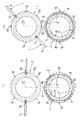
第1杭1に対する第2杭2の連結は、以下の要領で行う。
図1および図2に示すごとく、前記第2杭2の挿入は、軸芯Z1方向の係合部7の並びと、軸芯Z2方向の被係合部8の並びとが、周方向Yにおいて異なる位置となる状態で行う。第2杭2の挿入は、例えば、内嵌端部6の先端部10が外嵌端部4の基端部9に当接し、内嵌端部6の基端部9が外嵌端部4の先端部10に当接するまで行う。
前記第2杭2が所定の深さまで挿入されると、互いに係合すべき係合部7と被係合部8とは、軸芯Z1,Z2方向において異なる部位に位置する。この状態が図2(ロ)である。この状態で第2杭2を軸芯Z2周りに回転させれば、図2(ハ)のごとく前記係合部7と前記被係合部8とが係合し、第1杭1に対して第2杭2を連結することができる。
尚、当該第2杭2の挿入を容易にするためには、図1に示すごとく、前記内嵌端部6に係る先端部10の外周部と、前記外嵌端部4に係る先端部10の内周部とに、面取り部13を設けておくのがよい。
【0016】
第2杭2の回転作業を円滑に行うためには、例えば、図3(イ)(ロ)に示すごとく、第2杭本体5の外周部であって基端部9の近傍に回転作業用の把手14を取付けると便利である。当該把手14は取り外し自在に構成する。そのためには、前記外周部にボルト穴15を設けておき、端部に雄ねじ部を設けた把手14を螺入させる構成にするとよい。
また、第2杭2の回転作業を確実に行うためには、例えば図3(イ)(ロ)に示すごとく、第1杭1に係る外嵌端部4の先端部10の外周面10aと、第2杭2に係る第2杭本体5の外周面5aであって基端部9の近傍に夫々合わせマーク16を設けておくとよい。つまり、当該合わせマーク16が一致するまで第2杭2を回転させれば、係合部7と被係合部8とが確実に係合する。
【0017】
以上のごとく構成した係合部7と被係合部8とは、単に、前記第1杭1と前記第2杭2とが双方の軸芯Z1,Z2方向に沿って変位するのを阻止するに止まらず、前記外嵌端部4と前記内嵌端部6とを同軸芯状に嵌合させて、係合した前記係合部7と前記被係合部8とが前記軸芯Z1,Z2の径方向Xに離間するのを阻止するための離間阻止手段を構成する。
この結果、第1杭1と第2杭2との継手部に曲げ力が加わった場合、あるいは、引っ張り・圧縮力が加わった場合にも、図7に示すような前記外嵌端部4と前記内嵌端部6との離間が生じず、前記外嵌端部4および前記内嵌端部6の断面変形が抑制されて、強固な継手部を得ることができる。
【0018】
本発明のごとく、第2杭2を軸芯Z2の周りに所定の角度だけ回転させる場合には、当該回転操作を行うことができるよう係合部7と被係合部8とを形成する結果、杭の連結が終了した状態で継手部にガタが存在する場合がある。このようなガタが存在すると、継手部の強度は低下する。
これを防止するために、本発明の杭の継手部構造では、図4に示すごとく、係合部7と被係合部8との接当面17を、螺旋の一部を形成するよう軸芯Z1,Z2の周方向Yに対して斜めに形成してある。図4の場合には、個々の係合部7あるいは個々の被係合部8の上下面に逆の傾斜を設けてある。
本構成であれば、第2杭2を回転させる際に係合部7と被係合部8との間のガタを解消し、係合部7と被係合部8との当接力を高めて強固な継手部を得ることができる。
また、この場合には、第2杭2を回転させる際のストッパ機能が生じて、第2杭2を回転し過ぎることがなく、杭の連結作業を簡便なものにすることもできる。
【0019】
(その他)
前記第1杭本体3及び前記第2杭本体5は、高強度で加工性に優れている等の理由から、通常、圧延鋼管・鋳造管等の鋼管で構成することができる。ただし、特にこれに限定されるわけではなく、コンクリート製の杭であってもよい。コンクリート製の杭の場合には、あらかじめ形成した前記外嵌端部4あるいは前記内嵌端部6を杭の端部に埋設して用いる。
【0020】
(効果)
本発明の杭の継手部構造は、係合した係合部7と被係合部8とを第1杭1の径方向Xに離間させないようにするために、係合部7と被係合部8とに離間阻止手段を設けてある。
この結果、第1杭1と第2杭2との継手部に曲げ力が加わった場合、あるいは、引っ張り・圧縮力が加わった場合にも、前記外嵌端部4および前記内嵌端部6との断面変形が抑制されて外嵌端部4等が高い曲げ耐力を発揮し、強固な継手部を構成することができる。
また、第2杭2の連結に際しては、第2杭2を自身の軸芯Z2周りに所定の角度のみ回転させるだけでよいから、杭の連結作業が非常に簡便なものとなる。
さらに、連結作業の終了は、例えば第2杭2の回転角度をもって判断できるから、継手部の品質管理が容易となる。
この他、本発明の杭の継手部構造であれば、天候によって作業の進行が妨げられることも少ないから、工期の短縮、コストダウンが可能である等の利点も得られる。
【0021】
〔別実施形態〕
〈1〉 上記実施形態では、前記係合部7と前記被係合部8とをアリ溝状に構成したが、当該構成に限られるものではない。例えば、図5に示すごとく、杭の縦断面視における前記係合部7と前記被係合部8との断面形状を略T字状に形成して、離間阻止手段を構成するものであってもよい。
本構成の場合にも、外嵌端部4および内嵌端部6の断面形状の変形を阻止して、曲げ耐力等に優れた杭の継手部を得ることができる。
【0022】
〈2〉 上記実施形態では、係合部7と被係合部8とが径方向Xに離間しないように係合部7および被係合部8自身に離間阻止手段を形成した。しかし、離間阻止手段は、以下のごとく構成することもできる。
即ち、図6(イ)(ロ)に示すごとく、外嵌端部4および内嵌端部6の夫々の先端部10に環状の凸部18を設け、外嵌端部4および内嵌端部6の夫々の基端部9に基端溝部19を設ける。
外嵌端部4の環状の凸部18は、先端部10の内周側に設けてあり、内嵌端部6の環状の凸部18は先端部10の外周側に設けてある。
一方、内嵌端部6の基端部9と外嵌端部4の基端部9とには、全周に沿って基端溝部19を形成してある。双方の基端溝部19は、軸芯Z1,Z2方向に突出している。
本構成であれば、第2杭2を第1杭1に挿入した場合、あるいは、第2杭2と第1杭1との連結が終了した状態では、図6(ロ)に示すごとく、環状の凸部18と基端溝部19とが同軸芯状に係合する。特に、環状の凸部18と基端溝部19とは、軸芯Z1,Z2の径方向Xに当接する。
つまり、本構成であれば、継手部に曲げ力が加わった場合、或いは、軸芯方向に沿った過度の圧縮力・引張力が加わった場合に、先端部10と基端部9とが離間するのを防止する。例えば、継手部に曲げ力が加わると、外嵌端部4および内嵌端部6は図7(イ)のように変形して係合部7と被係合部8との係合度合いが弱まり、第2杭2が抜け出すおそれが生じるし、第2杭2の抜け出しが防止できても、外嵌端部4あるいは内嵌端部6が変形するおそれがあり、その場合には、継手部の耐力が低下する。しかし、本構成のごとく、環状の凸部18と基端溝部19とを設けておけば、継手部に曲げ力が加わった際の先端部10と基端部9との離間を抑制できる。特に、肉厚の薄くなりがちな内嵌端部6および外嵌端部4の先端部10の断面形状が円断面に維持されて、高い耐力を備えた継手部を得ることができる。
図6(イ)(ロ)では、杭の縦断面視における前記環状の凸部18および前記基端溝部19の断面形状を略矩形状としたが、当該構成に限られず、断面形状を例えば、三角形状等に構成してもよい。要するに、前記環状の凸部18と前記基端溝部19との係合によって、前記先端部10および前記基端部9の断面形状の変形を抑制できるものであれば何れの構成であってもよい。
さらに、本別実施形態では、前記係合部7と被係合部8とを略矩形状の断面に形成したが本構成に限られるものではない。即ち、図示は省略するが、前記環状の凸部18および前記基端溝部19を設けつつ、前記係合部7と前記被係合部8とを、図1・図2に示すような拡大突出部を有する形状に構成してもよい。この場合には、前記外嵌端部4と前記内嵌端部6との係合程度をさらに高めることができる。
【0023】
〈3〉
上記実施形態では、係合部7および被係合部8を軸芯Z1,Z2の周方向Yに断続的に配置した例を示した。しかし、上記に係合部7および被係合部8を単にネジ状に構成してもよい。ただし、その場合においても、前記係合部7などの断面形状は、例えばアリ溝形状とし、前記係合部7と前記被係合部8とが前記軸芯の径方向Xに離間しない構成とする。
本構成の場合、上記実施形態に比較して、係合部7等の製作の手間および第2杭2の螺合作業の手間が増大するものの、継手部の全周に亘って係合部7と被係合部8とが係合可能であるから、より強固な杭の継手部を得ることができる。
【0024】
尚、上記特許請求の範囲の記載中、図面を参照し、図面との対照を便利にするために符号を記すが、当該記入により本発明が添付図面の構成に限定されるものではない。
【図面の簡単な説明】
【図1】 本発明に係る杭の継手部構造を示す説明図
【図2】 杭の連結過程を示す縦断面図
【図3】 杭の連結過程を示す横断面図
【図4】 係合部および被係合部の傾斜状態を示す説明図
【図5】 別実施形態に係る杭の継手部構造を示す説明図
【図6】 別実施形態に係る杭の連結過程を示す縦断面図
【図7】 従来技術に係る杭の継手部構造を示す縦断面図
【符号の説明】
1 第1杭
2 第2杭
4 外嵌端部
6 内嵌端部
7 係合部
7a 拡大突出部
8 被係合部
9 外嵌端部・内嵌端部の基端部
10 外嵌端部・内嵌端部の先端部
11 外嵌端部の内壁部
12 内嵌端部の外壁部
13 先端部の面取り部
18 環状の凸部
19 基端溝部
Y 第1杭・第2杭の周方向[0001]
BACKGROUND OF THE INVENTION
In the present invention, a pair of external fitting end portions and internal fitting end portions that can be fitted to each other are separately formed in a first pile and a second pile adjacent in the axial direction, and the outer fitting end portion and the The inner wall portion of the outer fitting end portion is engaged with the engaging portion and the engaged portion that are engaged with each other so as to be prevented from being pulled out by a relative rotation operation around the shaft core in a state where the inner fitting end portion is fitted. And the joint part structure of the pile provided separately in the outer wall part of the said internal fitting end part.
[0002]
[Prior art]
Conventionally, as this type of pile joint structure, there has been a screw type as shown in FIG. That is, the
If the joint part structure of a pile is a screw type, many screw threads along the longitudinal direction of a pile will engage. Therefore, it has high proof stress with respect to the bending force etc. which act on a pile after a connection is complete | finished.
[0003]
[Problems to be solved by the invention]
However, the above-described conventional pile joint structure has the following problems.
For example, when a strong bending force is applied to the joint portion, the
In addition, when a strong tensile force is applied to the joint portion as shown in FIG. 7 (B), or when a strong compressive force is applied to the joint portion as shown in FIG. The
As described above, the joint portion that is likely to be deformed cannot exhibit sufficient joint yield strength, and there is still room for improvement.
An object of the present invention is to provide a pile joint structure having a high bending strength by eliminating the drawbacks of the prior art and suppressing deformation of the joint portion of the pile.
[0004]
[Means for Solving the Problems]
(Configuration 1)
As described in
(Action / Effect)
As in this configuration, if the engaged portion and the engaged portion are not separated in the radial direction of the first pile or the second pile, the external fitting end portion of the first pile and the second pile The contact state with the inner fitting end can be maintained well. For example, even when a bending force is applied to the joint portion of the pile, the contact area between the outer fitting end portion and the inner fitting end portion does not change. Therefore, it can suppress that the cross-sectional shape etc. of an outer fitting end part and an inner fitting end part change. As a result, a joint portion having a high bending strength can be obtained.
Moreover, since the said separation prevention means is provided in the said engaging part and the said to-be-engaged part, it can bear the bending force added to the joint part by the whole outer fitting end part and an inner fitting end part. it can.
[0005]
Furthermore, in order to constitute the separation preventing means, in the longitudinal cross-sectional view of the first pile or the second pile, one of the engaging portion and the engaged portion has a narrow width in the pile axis direction. An enlarged protrusion in which a narrow portion and a wide portion whose width in the pile axis direction is wider than the narrow portion protrudes in the pile radial direction, and the wide portion protrudes on the front side in the protruding direction from the narrow portion A groove shape having a narrow groove width portion in which the widened portion of the enlarged protruding portion can be engaged in the pile radial direction, and the enlarged protruding portion can be inserted from the circumferential direction of the pile. For example, a dovetail structure is conceivable for engaging the engaging portion having the enlarged protrusion and the groove-like engaged portion. In this case, not only when a bending force is applied to the joint portion, but also when a tensile force or a compressive force is applied, the separation between the outer fitting end portion and the inner fitting end portion is effectively prevented. A joint portion that exhibits a high yield strength against any external force can be configured.
[0006]
(Configuration 2 )
As described in
(Action / Effect)
In general, it is the opening end that is most likely to undergo cross-sectional deformation in a cylindrical body. That is, the opening end is thinner than the pile main body, and the degree of deformation restraint by the pile main body is less than that of the base end.
However, with this configuration, the distal end portion of the outer fitting end portion is prevented from being separated from the proximal end portion of the inner fitting end portion, so that the deformation of the distal end portion can be effectively prevented, and the bending force It is possible to obtain a joint portion that exhibits a high yield strength against the above.
[0007]
(Configuration 3 )
As described in
(Action / Effect)
In general, it is the opening end that is most likely to undergo cross-sectional deformation in a cylindrical body. That is, the opening end is thinner than the pile main body, and the degree of deformation restraint by the pile main body is less than that of the base end.
However, with this configuration, the distal end portion of the inner fitting end portion is prevented from being separated from the proximal end portion of the outer fitting end portion, so that the deformation of the distal end portion can be effectively prevented, and the bending force It is possible to obtain a joint portion that exhibits a high yield strength against the above.
(Configuration 4 )
As described in
(Action / Effect)
In general, it is the opening end that is most likely to undergo cross-sectional deformation in a cylindrical body. Even in the case of this configuration, it is considered that the tip of the first pile and the tip of the second pile are most easily deformed. That is, these tip portions are thinner than the first pile main body or the second pile main body, and are less deformed and restrained by the pile main body than the base end portion.
However, with this configuration, for example, the distal end portion of the inner fitting end portion is prevented from being separated from the proximal end portion of the outer fitting end portion, so that deformation of the distal end portion can be effectively prevented, and bending It is possible to obtain a joint portion that exhibits a high yield strength against force and the like.
[0008]
(Configuration 5 )
As described in
(Action / Effect)
With this configuration, when the inner fitting end portion is inserted into the outer fitting end portion, it is possible to avoid a situation in which both of them come into contact with each other and hinder the insertion of the inner fitting end portion, and the pile connection work can be smoothly performed. Can be achieved.
[0009]
(Configuration 6 )
As described in
(Action / Effect)
If it is this structure, since the joint part length of the pile in the longitudinal direction of a 1st pile and a 2nd pile can be ensured reliably, the joint part which has higher bending strength can be obtained.
(Configuration 7 )
As described in
(Action / Effect)
As in this configuration, if the contact surfaces of the engaging portion and the engaged portion are inclined, the contact force between the engaging portion and the engaged portion can be increased when rotating the second pile, A strong joint part can be obtained.
Moreover, even when there is a backlash between the engaging portion and the engaged portion at the time when the second pile is inserted into the first pile, such backlash is eliminated along with the rotation of the second pile. Therefore, the manufacturing accuracy of the engaging portion and the like can be eased.
Furthermore, in the case of this structure, the stopper function at the time of rotating a 2nd pile arises. That is, since it is possible to avoid inconveniences such as the engagement between the engaging portion and the engaged portion being disengaged by rotating the second pile too much, the connecting operation of the pile becomes simple.
[0010]
DETAILED DESCRIPTION OF THE INVENTION
Embodiments of the present invention will be described below with reference to the drawings.
[0011]
(Overview)
As shown in FIG. 1, the pile joint structure of the present invention is, for example, between the
Specifically, the
In the joint part structure of a pile according to the present invention, the inner
[0012]
(Engagement part and engaged part)
The
The outer
An
A plurality of the engaging
In the present embodiment, the engaging
It is assumed that the positional relationship between the engaging
[0013]
On the other hand, the inner
[0014]
In the present embodiment, the engaging
That is, for example, as shown in FIG. 1, the engaging
One engaged
However, the difference in the shape of whether it is the enlarged projecting
[0015]
The
As shown in FIGS. 1 and 2, the
When the
In order to facilitate the insertion of the
[0016]
In order to smoothly rotate the
Moreover, in order to perform the rotation operation | work of the
[0017]
The engaging
As a result, even when a bending force is applied to the joint portion between the
[0018]
As in the present invention, when the
In order to prevent this, in the joint structure of a pile according to the present invention, as shown in FIG. 4, the
If it is this structure, when rotating the
Moreover, in this case, the stopper function at the time of rotating the
[0019]
(Other)
The said 1st pile
[0020]
(effect)
The joint part structure of the pile of the present invention is such that the
As a result, even when a bending force is applied to the joint portion between the
Further, when the
Furthermore, since the end of the connection work can be determined from the rotation angle of the
In addition, since the pile joint structure of the present invention is less likely to prevent work from proceeding due to the weather, advantages such as shortening the construction period and reducing costs are also obtained.
[0021]
[Another embodiment]
<1> In the above embodiment, the engaging
Also in the case of this configuration, it is possible to obtain a joint portion of a pile excellent in bending strength and the like by preventing the deformation of the cross-sectional shapes of the outer
[0022]
<2> In the above embodiment, the separation preventing means is formed in the
That is, as shown in FIGS. 6 (a) and 6 (b), an annular
The annular
On the other hand, a proximal
In this configuration, when the
In other words, with this configuration, the
6A and 6B, the cross-sectional shapes of the annular
Furthermore, in this another embodiment, although the said
[0023]
<3>
In the said embodiment, the example which arrange | positioned the
In the case of this structure, compared with the said embodiment, although the effort of manufacture of the
[0024]
In the description of the appended claims, reference is made to the drawings to refer to the drawings for convenience of comparison with the drawings, but the present invention is not limited to the configuration of the attached drawings by such entry.
[Brief description of the drawings]
FIG. 1 is an explanatory view showing a joint structure of a pile according to the present invention. FIG. 2 is a longitudinal sectional view showing a connecting process of piles. FIG. 3 is a cross-sectional view showing a connecting process of piles. Explanatory drawing which shows the inclination state of a to-be-engaged part, FIG. 5 Explanatory drawing which shows the joint part structure of the pile which concerns on another embodiment FIG. 6 A longitudinal cross-sectional view which shows the connection process of the pile which concerns on another embodiment 7] Longitudinal sectional view showing the joint structure of a pile according to the prior art [Explanation of symbols]
DESCRIPTION OF
Claims (7)
係合した前記係合部(7)と前記被係合部(8)とが前記第1杭あるいは前記第2杭の径方向に離間するのを阻止するための離間阻止手段を、前記係合部(7)と前記被係合部(8)とに設けてあるとともに、
前記離間阻止手段を構成するのに、第1杭あるいは第2杭の縦断面視において、前記係合部(7)および前記被係合部(8)のうちの一方を、杭軸芯方向の幅が狭い幅狭部分と杭軸芯方向の幅が前記幅狭部分よりも幅広の幅広部分とが杭径方向に突出し、かつ、前記幅広部分が前記幅狭部分よりも突出方向先端側で突出している拡大突出部(7a)を有する形状とし、他方を前記拡大突出部(7a)が杭周方向から挿入可能で、かつ、前記拡大突出部(7a)の幅広部分を杭径方向に係合可能な幅狭の溝幅部分を備えた溝形状としてある杭の継手部構造。A pair of outer fitting end portions (4) and inner fitting end portions (6) that can be fitted to each other are formed separately on the first pile (1) and the second pile (2) adjacent in the axial direction. In the state in which the outer fitting end portion (4) and the inner fitting end portion (6) are fitted, the engaging portions (7 are engaged with each other so as to be prevented from being pulled out by a relative rotation operation around the axis. ) And the engaged portion (8) are provided separately on the inner wall portion (11) of the outer fitting end portion (4) and the outer wall portion (12) of the inner fitting end portion (6). The joint part structure of
Separation preventing means for preventing the engaged portion (7) engaged and the engaged portion (8) from separating in the radial direction of the first pile or the second pile, the engagement Provided in the part (7) and the engaged part (8),
To constitute the separation preventing means, in the longitudinal sectional view of the first pile or the second pile, one of the engaging portion (7) and the engaged portion (8) is arranged in the pile axis direction. A narrow portion having a narrow width and a wide portion having a width in the pile axis direction wider than the narrow portion protrude in the pile radial direction, and the wide portion protrudes on the front side in the protruding direction from the narrow portion. The other side of the enlarged protrusion (7a) can be inserted from the circumferential direction of the pile, and the wide part of the enlarged protrusion (7a) is engaged in the pile radial direction. Pile joint structure as a groove shape with possible narrow groove width part .
前記外嵌端部(4)の先端部(10)に凸部(18)を設けると共に、
前記内嵌端部(6)の基端部(9)に、前記第1杭(1)あるいは前記第2杭(2)の軸芯方向から前記凸部(18)に係合可能な基端溝部(19)を設けてある杭の継手部構造。A pair of outer fitting end portions (4) and inner fitting end portions (6) that can be fitted to each other are formed separately on the first pile (1) and the second pile (2) adjacent in the axial direction. In the state in which the outer fitting end portion (4) and the inner fitting end portion (6) are fitted, the engaging portions (7 are engaged with each other so as to be prevented from being pulled out by a relative rotation operation around the axis. ) And the engaged portion (8) are provided separately on the inner wall portion (11) of the outer fitting end portion (4) and the outer wall portion (12) of the inner fitting end portion (6). The joint part structure of
While providing a convex part (18) in the tip part (10) of the external fitting end part (4),
A base end engageable with the convex portion (18) from the axial direction of the first pile (1) or the second pile (2) to the base end portion (9) of the internal fitting end portion (6) Pile joint structure with a groove (19).
前記内嵌端部(6)の先端部(10)に凸部(18)を設けると共に、
前記外嵌端部(4)の基端部(9)に、前記第1杭(1)あるいは前記第2杭(2)の軸芯方向から前記凸部(18)に係合可能な基端溝部(19)を設けてある杭の継手部構造。A pair of outer fitting end portions (4) and inner fitting end portions (6) that can be fitted to each other are formed separately on the first pile (1) and the second pile (2) adjacent in the axial direction. In the state in which the outer fitting end portion (4) and the inner fitting end portion (6) are fitted, the engaging portions (7 are engaged with each other so as to be prevented from being pulled out by a relative rotation operation around the axis. ) And the engaged portion (8) are provided separately on the inner wall portion (11) of the outer fitting end portion (4) and the outer wall portion (12) of the inner fitting end portion (6). The joint part structure of
While providing a convex part (18) at a tip part (10) of the internal fitting end part (6),
A base end that can be engaged with the convex portion (18) from the axial direction of the first pile (1) or the second pile (2) to the base end portion (9) of the external fitting end portion (4) Pile joint structure with a groove (19).
前記外嵌端部(4)および前記内嵌端部(6)の夫々の先端部(10)に環状の凸部 (18)を設けると共に、
前記外嵌端部(4)および前記内嵌端部(6)の夫々の基端部(9)に、前記第1杭 (1)あるいは前記第2杭(2)の軸芯方向から前記環状の凸部(18)に係合可能な基端溝部(19)を設けてある杭の継手部構造。A pair of outer fitting end portions (4) and inner fitting end portions (6) that can be fitted to each other are formed separately on the first pile (1) and the second pile (2) adjacent in the axial direction. In the state in which the outer fitting end portion (4) and the inner fitting end portion (6) are fitted, the engaging portions (7 are engaged with each other so as to be prevented from being pulled out by a relative rotation operation around the axis. ) And the engaged portion (8) are provided separately on the inner wall portion (11) of the outer fitting end portion (4) and the outer wall portion (12) of the inner fitting end portion (6). The joint part structure of
While providing an annular convex part (18) at each front-end | tip part (10) of the said external fitting end part (4) and the said internal fitting end part (6),
The base end portion (9) of the outer fitting end portion (4) and the inner fitting end portion (6) is connected to the annular portion from the axial direction of the first pile (1) or the second pile (2). A pile joint structure in which a base end groove portion (19) that can be engaged with the convex portion (18) is provided.
Priority Applications (1)
| Application Number | Priority Date | Filing Date | Title |
|---|---|---|---|
| JP20291997A JP3755966B2 (en) | 1997-07-29 | 1997-07-29 | Pile joint structure |
Applications Claiming Priority (1)
| Application Number | Priority Date | Filing Date | Title |
|---|---|---|---|
| JP20291997A JP3755966B2 (en) | 1997-07-29 | 1997-07-29 | Pile joint structure |
Related Child Applications (1)
| Application Number | Title | Priority Date | Filing Date |
|---|---|---|---|
| JP2005178354A Division JP3877746B2 (en) | 2005-06-17 | 2005-06-17 | Pile joint structure |
Publications (2)
| Publication Number | Publication Date |
|---|---|
| JPH1143937A JPH1143937A (en) | 1999-02-16 |
| JP3755966B2 true JP3755966B2 (en) | 2006-03-15 |
Family
ID=16465343
Family Applications (1)
| Application Number | Title | Priority Date | Filing Date |
|---|---|---|---|
| JP20291997A Expired - Lifetime JP3755966B2 (en) | 1997-07-29 | 1997-07-29 | Pile joint structure |
Country Status (1)
| Country | Link |
|---|---|
| JP (1) | JP3755966B2 (en) |
Families Citing this family (12)
| Publication number | Priority date | Publication date | Assignee | Title |
|---|---|---|---|---|
| KR100733719B1 (en) * | 2006-02-15 | 2007-07-04 | (주)핸스건설 | Length control type steel pipe strut |
| JP5941295B2 (en) * | 2012-02-15 | 2016-06-29 | 株式会社技研製作所 | Pile joint, joint for steel parts, method for joining piles, and method for joining steel parts |
| WO2014080824A1 (en) | 2012-11-21 | 2014-05-30 | 新日鐵住金株式会社 | Joint structure for steel-pipe pile, and steel-pipe pile |
| JP5880421B2 (en) * | 2012-12-25 | 2016-03-09 | 新日鐵住金株式会社 | Steel pipe joint, steel pipe joint structure, and steel pipe joint method |
| JP2015086619A (en) * | 2013-10-31 | 2015-05-07 | シントク工業株式会社 | Steel pipe pile connection structure |
| AU2014358146B2 (en) * | 2013-12-06 | 2017-01-05 | Nippon Steel Corporation | Joint structure for steel pipe pile |
| JP6344225B2 (en) * | 2013-12-26 | 2018-06-20 | 新日鐵住金株式会社 | Steel pipe pile joint structure |
| TW201608084A (en) * | 2014-07-24 | 2016-03-01 | 新日鐵住金股份有限公司 | Joint structure of steel pipe pile |
| JP6439596B2 (en) * | 2014-07-24 | 2018-12-19 | 新日鐵住金株式会社 | Steel pipe pile joint structure |
| JP6897514B2 (en) * | 2017-11-14 | 2021-06-30 | 日本製鉄株式会社 | Joint structure of steel pipe pile |
| SG11202108809QA (en) * | 2019-02-12 | 2021-09-29 | Giken Ltd | Pile joint, pile coupling structure, and pile coupling method |
| BR112021015517B1 (en) | 2019-02-12 | 2022-12-27 | Giken Ltd. | CONNECTION OF PILES, PILE COUPLING STRUCTURE, AND PILE COUPLING METHOD |
-
1997
- 1997-07-29 JP JP20291997A patent/JP3755966B2/en not_active Expired - Lifetime
Also Published As
| Publication number | Publication date |
|---|---|
| JPH1143937A (en) | 1999-02-16 |
Similar Documents
| Publication | Publication Date | Title |
|---|---|---|
| JP3877746B2 (en) | Pile joint structure | |
| JP3755966B2 (en) | Pile joint structure | |
| TWI357955B (en) | Blind fastener | |
| US7883119B2 (en) | Gland seal and corresponding assembly | |
| KR102065742B1 (en) | Connector of steel piles | |
| US7748754B2 (en) | Pipe section provided with a socket end part | |
| JP5619975B2 (en) | Pile joint structure | |
| JPH1143936A (en) | Pile coupling part structure | |
| JP4274875B2 (en) | Columnar | |
| CN111886416A (en) | Self-locking bolt | |
| JPH0785822B2 (en) | Method for manufacturing tripod type joint inner member | |
| JPS587123Y2 (en) | Caulking joint shaft joint | |
| JP2994252B2 (en) | Joint structure between ball joint and rod of space truss | |
| JP4578029B2 (en) | Pile head structure and pile head bracket | |
| JP2543945Y2 (en) | Steel pipe for connection | |
| CN217629857U (en) | Insertion-holding retaining sleeve for building and butt joint assembly | |
| JP4601224B2 (en) | Threaded joint structure of steel pipe pile | |
| JP3488806B2 (en) | Segment joint structure | |
| JP3819105B2 (en) | segment | |
| JPH0771430A (en) | Retaining ring | |
| JPH0417897Y2 (en) | ||
| JP4142213B2 (en) | Screw hardware and high strength bolt joint structure | |
| JP2563703Y2 (en) | Pipe fittings | |
| JP2525192Y2 (en) | Segment for tunnel | |
| JP2731094B2 (en) | Locking device |
Legal Events
| Date | Code | Title | Description |
|---|---|---|---|
| A521 | Written amendment |
Free format text: JAPANESE INTERMEDIATE CODE: A523 Effective date: 20040611 |
|
| A977 | Report on retrieval |
Free format text: JAPANESE INTERMEDIATE CODE: A971007 Effective date: 20050418 |
|
| A131 | Notification of reasons for refusal |
Free format text: JAPANESE INTERMEDIATE CODE: A131 Effective date: 20050421 |
|
| A521 | Written amendment |
Free format text: JAPANESE INTERMEDIATE CODE: A523 Effective date: 20050617 |
|
| TRDD | Decision of grant or rejection written | ||
| A01 | Written decision to grant a patent or to grant a registration (utility model) |
Free format text: JAPANESE INTERMEDIATE CODE: A01 Effective date: 20051208 |
|
| A61 | First payment of annual fees (during grant procedure) |
Free format text: JAPANESE INTERMEDIATE CODE: A61 Effective date: 20051220 |
|
| R150 | Certificate of patent or registration of utility model |
Free format text: JAPANESE INTERMEDIATE CODE: R150 |
|
| FPAY | Renewal fee payment (event date is renewal date of database) |
Free format text: PAYMENT UNTIL: 20090106 Year of fee payment: 3 |
|
| FPAY | Renewal fee payment (event date is renewal date of database) |
Free format text: PAYMENT UNTIL: 20100106 Year of fee payment: 4 |
|
| FPAY | Renewal fee payment (event date is renewal date of database) |
Free format text: PAYMENT UNTIL: 20100106 Year of fee payment: 4 |
|
| FPAY | Renewal fee payment (event date is renewal date of database) |
Free format text: PAYMENT UNTIL: 20110106 Year of fee payment: 5 |
|
| FPAY | Renewal fee payment (event date is renewal date of database) |
Free format text: PAYMENT UNTIL: 20110106 Year of fee payment: 5 |
|
| FPAY | Renewal fee payment (event date is renewal date of database) |
Free format text: PAYMENT UNTIL: 20120106 Year of fee payment: 6 |
|
| FPAY | Renewal fee payment (event date is renewal date of database) |
Free format text: PAYMENT UNTIL: 20120106 Year of fee payment: 6 |
|
| FPAY | Renewal fee payment (event date is renewal date of database) |
Free format text: PAYMENT UNTIL: 20130106 Year of fee payment: 7 |
|
| FPAY | Renewal fee payment (event date is renewal date of database) |
Free format text: PAYMENT UNTIL: 20140106 Year of fee payment: 8 |
|
| EXPY | Cancellation because of completion of term |