JP3752283B2 - Press machine - Google Patents
Press machine Download PDFInfo
- Publication number
- JP3752283B2 JP3752283B2 JP28438695A JP28438695A JP3752283B2 JP 3752283 B2 JP3752283 B2 JP 3752283B2 JP 28438695 A JP28438695 A JP 28438695A JP 28438695 A JP28438695 A JP 28438695A JP 3752283 B2 JP3752283 B2 JP 3752283B2
- Authority
- JP
- Japan
- Prior art keywords
- punch
- die
- chamfering
- workpiece
- work
- Prior art date
- Legal status (The legal status is an assumption and is not a legal conclusion. Google has not performed a legal analysis and makes no representation as to the accuracy of the status listed.)
- Expired - Fee Related
Links
Images


Description
【0001】
【発明の属する技術分野】
本発明は、プレス装置等により孔あけ加工されたワ−クの歪み(反り)を無くすと共にバリをつぶして面取りする作業を同時に行うことの出来るプレス装置に関するものである。
【0002】
【従来の技術】
一般に、プレス装置により孔あけ加工された板材(以下、ワ−クという)は、孔あけ加工により歪んで反りが発生するばかりでなく、バリも形成されるので、より高品質な製品とするためには歪みを取り、バリを除去し、且つ、面取りを施さなければならない。そこで、従来は、前記ワ−クの歪みを取ろうとする場合は、歪み矯正機を用いており、また、バリを潰して面取りする場合には、プレス装置に面取り型を取付けてバリ取りを行い、必要に応じてドリルにより面取りを行っていた。また、弾性を有する研磨ロ−ルを用いてバリの突出面を研磨し、かつ、面取りを行なう研磨装置を用いて、ワ−クのバリ取りや面取りをすることも行われていた。
【0003】
而して、従来の面取り型は、プレス装置に装着して用いるもので、例えば、図7に示すように、外形がワ−クWの加工孔Waの内形より少し大きいパンチPと、弾性体1に付勢されて前記パンチPより突出し加工すべきワ−クWを載置するアッパ−プレ−ト2とを取付けたパンチホルダ−Hと、前記パンチPに対する面を平坦に形成したダイDとから成り、前記アッパ−プレ−ト2の上に前記ワ−クWを載置し、ダイDを下降させてワ−クWをパンチPに圧接させることにより面取りを行うものであるが、この面取り型ではバリを潰しながら、一定の面取りまでは出来るが、面取り量の調整や適切な歪み取りが困難であったため、従来は、バリ取りの後、別工程でドリル等によって前記バリ取りに伴う面取りよりも更に深い面取りを行ったり、或は、次の工程で歪み矯正機により歪み取りを行っていたのである。
【0004】
従って、従来、プレス装置により孔あけ加工されたワ−クWを完全な製品とするためには、別に面取り型,ドリル等の工具及び歪み矯正機が必要とされ、しかも、ドリル等による面取りと歪み矯正機による歪み取りとは別工程で行われるため、プレス装置以外の設備が必要となるばかりでなく、そのための作業も増えて、加工コストの高騰を招くという問題がある。
【0005】
従って、プレス装置等により孔あけ加工されたワ−クの歪み取り,孔周辺のバリ取り及び面取りを、一回の作業で行うことが出来、且つ、面取りの量を調節できるプレス装置が開発されれば、極めて有用されるものと考えられる。
【0006】
【発明が解決しようとする課題】
本発明は、上述のような従来技術に鑑み、プレス装置等により孔あけ加工されたワ−クの孔周辺のバリ取り及び面取りと歪み取りとを、一回の作業で行うことが出来、且つ、面取りの量を調節できるプレス装置を提供することを、その課題とするものである。
【0007】
【課題を解決するための手段】
上記課題を解決することを目的としてなされた本発明プレス装置の構成は、加工すべきワ−クの孔内形状より少し大きい外形のパンチ及び、弾性体に付勢されて常態では前記パンチより突出し加圧されればパンチの面より凹陥するワ−ク載置用又はワ−ク押え用プレ−トとを保持するパンチホルダ−と、前記パンチに対する面に該パンチの外形より大きい内形の欠所を設けたダイとを具備したことを特徴とするものである。
【0008】
即ち、本発明プレス装置は、ダイのパンチに対する面にパンチの外形より大きい欠所を設けることにより、ダイをパンチに、または、パンチをダイに向けて作動させれば、ワ−クの孔周辺に形成されているバリを除去すると共に面取りが出来ると同時に、ワ−クの加工された孔周辺がダイの欠所に入り込み、歪みによる反りとは逆の反りが生じて歪みを消去し、歪みを矯正することが出来るようにしたものである。なお、面取りの量は、ダイに設ける欠所の大きさ、或は、ダイの下死点の制御により調整できる。
【0009】
【発明の実施の形態】
次に、本発明の実施の形態を図により説明する。図1は本発明プレス装置の要部の断面図、図2は図1の装置によりワ−クの歪み及びバリ取り作業を行う寸前の状態を示す概略図、図3は同じく前記作業を行った状態の概略図、図4は前記作業を終了し、ダイをパンチから離した状態の概略図、図5はワ−クの面取りを大きくする場合のダイに設けた欠所の大きさを示す概略図、図6はワ−クの面取りを小さくする場合のダイに設けた欠所の大きさを示す概略図である。
【0010】
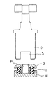
図1において、パンチP,弾性体1,ワ−クを載置するアッパ−プレ−ト2,パンチホルダ−H及びダイDは前出の図7に示した従来装置と同様で、本発明においては、前記ダイDのパンチPに対する面にパンチPの外形より大きい内形の欠所3を設けてある。尚、上記弾性体1としてはウレタンゴムのような合成樹脂製品やバネなどが用いられる。
【0011】
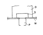
上記のように構成される本発明プレス装置により、ワ−クWの孔Waあけ加工時に形成された歪みC及びバリBを除去する作業は、次のようにして行われる。まず、図2に示したように、パンチホルダ−Hに取付けたアッパ−プレ−ト2(図示せず)上にワ−クWを載置し、次いで、図3に示したように、ダイDをパンチPに向け作動させると、ワ−クWのバリBはパンチPに衝当され潰されて除去されると共に面取りFも行われる一方、ワ−クWの歪みC部分がダイDの欠所3内に入り込んで該歪みCも除去され、ダイDを上動させれば、図4に示したように、ワ−クWはバリ取り,面取り及び歪み取りされた製品となる。
【0012】
また、本発明装置においては、ダイDに設ける欠所3の内形の大きさAを変化させることにより、ワ−クWの面取り量を調節することが出来る。即ち、ワ−クWの面取りを大きくする場合は、欠所3の内形の大きさAは、図5に示したように、パンチPの外形より少し大きくし、また、同じく面取りを小さくする場合は、図6に示したように、パンチPの外形より十分大きくすればよい。なお、面取り量は、ダイDの下死点を制御することによっても調整可能である。
【0013】
上記の実施の形態においては、パンチPを下に、ダイDを上に配置する例について述べたが、本発明はこれに限られるものではなく、パンチPを上に、ダイDを下に配置させるようにしてもよい。この場合は、ワ−クWの向きは図2の状態と逆向きにして加工するものとする。
【0014】
【発明の効果】
本発明は上述のとおりであって、パンチの外形を加工すべきワ−クの孔形状より少し大きくし、ダイの前記パンチに対する面に該パンチの外形より大きい内形の欠所を設け、ワ−クを載置するプレ−トを常態にあっては前記パンチの面より突出させ、ダイの作動時に前記パンチ面より凹陥させるようにしたから、前記プレ−ト上にワ−クを載置し、ダイを作動させれば、上述のように、従来個々に作業を行っていたバリ取り,面取り及び歪み取りを、一回の作業で行うことが出来る。
【0015】
また、タレットパンチプレス機において、上下のタレットに孔あけ加工用のパンチとダイを装着するとともに、前記上下のタレットに、ワ−クのバリの発生面側に本発明のパンチを、そして反対側にダイを設置することにより、ワ−クを一度タレットパンチプレス機にセットすれば、孔あけ加工からバリ取り,面取り,歪取りの各加工を一度にできるので、作業能率を大幅に向上させ、加工コストの低減を図ることが出来る。
【図面の簡単な説明】
【図1】本発明プレス装置の要部の断面図。
【図2】図1の装置によりワ−クのバリ取り,面取り,歪み取り作業を行う寸前の状態を示す概略図。
【図3】前記作業を行った状態の概略図。
【図4】前記作業を終了し、ダイをパンチから離した状態の概略図。
【図5】ワ−クの面取りを大きくする場合のダイに設けた欠所の大きさを示す概略図。
【図6】ワ−クの面取りを小さくする場合のダイに設けた欠所の大きさを示す概略図。
【図7】従来のプレス装置の要部の断面図。
【符号の説明】
P パンチ
D ダイ
H パンチホルダ−
1 弾性体
2 アッパ−プレ−ト(ワ−ク載置用)
3 ダイに設けた欠所
W ワ−ク
Wa ワ−クの加工孔
B バリ
C 歪み[0001]
BACKGROUND OF THE INVENTION
The present invention relates to a press apparatus that can simultaneously perform the work of eliminating chamfering by crushing burrs while eliminating distortion (warpage) of a work punched by a press apparatus or the like.
[0002]
[Prior art]
In general, a plate material (hereinafter referred to as a workpiece) drilled by a press device is not only distorted and warped by the drilling process, but also forms burrs, so that a higher quality product can be obtained. Must be distorted, burr removed and chamfered. Therefore, conventionally, when trying to remove the distortion of the work, a distortion correcting machine is used, and when crushing by crushing the burr, a chamfering die is attached to the press device to perform deburring. If necessary, chamfering was performed with a drill. In addition, a burr protruding surface is polished using a polishing roll having elasticity, and a workpiece is deburred or chamfered using a polishing apparatus that performs chamfering.
[0003]
Thus, the conventional chamfering die is used by being mounted on a press device. For example, as shown in FIG. 7, the punch P is slightly larger than the inner shape of the work hole Wa of the workpiece W, and the elastic A punch holder H to which an
[0004]
Therefore, conventionally, in order to make the workpiece W drilled by a press device into a complete product, a chamfering die, a tool such as a drill, and a distortion correcting machine are separately required. Since it is performed in a separate process from the distortion removal by the strain straightening machine, not only equipment other than the press device is required, but there is a problem that the work for it increases and the processing cost increases.
[0005]
Therefore, a press machine has been developed that can perform distortion removal, deburring and chamfering around a hole that has been drilled by a press machine, etc. in a single operation, and the amount of chamfering can be adjusted. If so, it is considered extremely useful.
[0006]
[Problems to be solved by the invention]
In view of the prior art as described above, the present invention can perform deburring, chamfering, and distortion removal around a hole of a work that has been drilled by a press device or the like in a single operation, and It is an object of the present invention to provide a press device capable of adjusting the amount of chamfering.
[0007]
[Means for Solving the Problems]
The configuration of the press device of the present invention, which has been made for the purpose of solving the above-mentioned problems, is a punch having an outer shape slightly larger than the inner shape of the work to be machined and an elastic body that is normally biased to protrude from the punch. A punch holder for holding a workpiece mounting plate or a workpiece holding plate which is recessed from the surface of the punch when pressed, and an inner shape larger than the outer shape of the punch on the surface of the punch. And a die provided with a place.
[0008]
That is, the press device according to the present invention is provided with a notch larger than the outer shape of the punch on the surface of the die punch, so that if the die is operated toward the punch or the punch toward the die, At the same time as removing the burrs formed on the surface of the die and chamfering it, the periphery of the hole where the workpiece is processed enters the notch of the die, causing warpage opposite to warpage due to distortion, eliminating the distortion, and Can be corrected. The amount of chamfering can be adjusted by controlling the size of the notch provided in the die or the bottom dead center of the die.
[0009]
DETAILED DESCRIPTION OF THE INVENTION
Next, embodiments of the present invention will be described with reference to the drawings. FIG. 1 is a cross-sectional view of the main part of the press apparatus according to the present invention, FIG. 2 is a schematic view showing a state immediately before a work is distorted and deburred by the apparatus shown in FIG. FIG. 4 is a schematic diagram showing a state in which the operation is completed and the die is separated from the punch, and FIG. FIG. 6 and FIG. 6 are schematic views showing the size of the notch provided in the die when the chamfering of the work is reduced.
[0010]
In FIG. 1, the punch P, the elastic body 1, the
[0011]
The operation of removing the strain C and the burrs B formed during the hole Wa drilling of the workpiece W by the press device of the present invention configured as described above is performed as follows. First, as shown in FIG. 2, the workpiece W is placed on the upper plate 2 (not shown) attached to the punch holder H, and then, as shown in FIG. When D is operated toward the punch P, the burrs B of the work W are abutted against the punch P and are removed by being crushed, and the chamfering F is also performed. If the distortion C is also removed by entering the
[0012]
In the apparatus of the present invention, the chamfering amount of the work W can be adjusted by changing the size A of the inner shape of the
[0013]
In the above embodiment, the example in which the punch P is disposed below and the die D is disposed above has been described. However, the present invention is not limited to this, and the punch P is disposed above and the die D is disposed below. You may make it make it. In this case, it is assumed that the workpiece W is processed in the direction opposite to that shown in FIG.
[0014]
【The invention's effect】
The present invention is as described above, wherein the outer shape of the punch is made slightly larger than the hole shape of the work to be machined, and an inner shape notch larger than the outer shape of the punch is provided on the surface of the die with respect to the punch. -Since the plate on which the workpiece is placed is normally protruded from the surface of the punch and is recessed from the punch surface when the die is operated, the workpiece is placed on the plate. When the die is operated, deburring, chamfering, and distortion removal, which have conventionally been performed individually as described above, can be performed in a single operation.
[0015]
Further, in the turret punch press machine, the punch and die for drilling are mounted on the upper and lower turrets, the punch of the present invention is applied to the upper and lower turrets on the side where the workpiece burrs are generated, and the opposite side. By installing a die on the turret punch press once the work is set, drilling, deburring, chamfering, and distortion removal can be performed at once, greatly improving work efficiency. The processing cost can be reduced.
[Brief description of the drawings]
FIG. 1 is a cross-sectional view of a main part of a press apparatus according to the present invention.
FIG. 2 is a schematic view showing a state just before performing work deburring, chamfering, and distortion removal work with the apparatus of FIG. 1;
FIG. 3 is a schematic view showing a state in which the operation is performed.
FIG. 4 is a schematic view showing a state in which the operation is completed and the die is separated from the punch.
FIG. 5 is a schematic view showing the size of a notch provided in a die when the chamfering of the workpiece is increased.
FIG. 6 is a schematic diagram showing the size of a notch provided in a die when the chamfering of the work is reduced.
FIG. 7 is a cross-sectional view of a main part of a conventional press device.
[Explanation of symbols]
P Punch D Die H Punch holder
1
3 Wake in the die W work
Wa Work hole B Burr C Distortion
Claims (1)
Priority Applications (1)
| Application Number | Priority Date | Filing Date | Title |
|---|---|---|---|
| JP28438695A JP3752283B2 (en) | 1995-10-06 | 1995-10-06 | Press machine |
Applications Claiming Priority (1)
| Application Number | Priority Date | Filing Date | Title |
|---|---|---|---|
| JP28438695A JP3752283B2 (en) | 1995-10-06 | 1995-10-06 | Press machine |
Publications (2)
| Publication Number | Publication Date |
|---|---|
| JPH09103828A JPH09103828A (en) | 1997-04-22 |
| JP3752283B2 true JP3752283B2 (en) | 2006-03-08 |
Family
ID=17677920
Family Applications (1)
| Application Number | Title | Priority Date | Filing Date |
|---|---|---|---|
| JP28438695A Expired - Fee Related JP3752283B2 (en) | 1995-10-06 | 1995-10-06 | Press machine |
Country Status (1)
| Country | Link |
|---|---|
| JP (1) | JP3752283B2 (en) |
Families Citing this family (6)
| Publication number | Priority date | Publication date | Assignee | Title |
|---|---|---|---|---|
| JP4513995B2 (en) * | 1999-06-09 | 2010-07-28 | 株式会社アマダ | Turret punch press and processing method using the turret punch press |
| DE102004020483A1 (en) | 2004-04-26 | 2005-11-17 | Trumpf Werkzeugmaschinen Gmbh + Co. Kg | Tool, machine and method for deburring cutting edges on workpieces |
| DE102011089682B4 (en) | 2011-12-22 | 2013-08-01 | Pass Stanztechnik Ag | Die for a punching device, punching tool for a punching device with such a die and method for cutting out workpiece parts from workpieces with a corresponding die |
| JP5910261B2 (en) * | 2012-04-10 | 2016-04-27 | 株式会社ジェイテクト | Manufacturing method and manufacturing apparatus for link for power transmission chain |
| CN113441625A (en) * | 2021-06-15 | 2021-09-28 | 达奥(芜湖)汽车制品有限公司 | Development of control arm hole flanging die |
| CN113523091B (en) * | 2021-06-23 | 2022-07-19 | 东风柳州汽车有限公司 | 7-shaped hole machining method |
-
1995
- 1995-10-06 JP JP28438695A patent/JP3752283B2/en not_active Expired - Fee Related
Also Published As
| Publication number | Publication date |
|---|---|
| JPH09103828A (en) | 1997-04-22 |
Similar Documents
| Publication | Publication Date | Title |
|---|---|---|
| CN110561045B (en) | Workpiece machining method | |
| JP3752283B2 (en) | Press machine | |
| JP3803449B2 (en) | Die device for punching | |
| JP2002045929A (en) | Die apparatus and deburring method with using the apparatus | |
| US20020070508A1 (en) | Jaw for a jaw chuck | |
| JP4527252B2 (en) | Punch mold | |
| JP2659656B2 (en) | Die height adjuster | |
| US20040188268A1 (en) | Manufacturing procedure of hand tool | |
| JP4691238B2 (en) | Female replacement blade disposal delay device | |
| CN211276149U (en) | Stamping die and stamping machine tool | |
| CN219254344U (en) | Grinding wheel type diamond saw blade | |
| JP3754148B2 (en) | Sheet metal punching method and punch die used in the same method | |
| CN214351360U (en) | Flat grinding device | |
| JPH08267158A (en) | Die | |
| JP3469929B2 (en) | Deburring method and punching die for punch press | |
| JPH08263B2 (en) | Mold surface treatment method and mold | |
| JP3064759U (en) | Punching mold | |
| CN114273858A (en) | Machining method for reducing deformation of frame type thin-wall part | |
| JP3131334B2 (en) | Polishing and regeneration structure of punches in mold equipment | |
| JP2857497B2 (en) | Press mold | |
| JP2000158059A (en) | Scrap floating prevention die device | |
| JPH06234028A (en) | Stamping die for mass production | |
| JPH05192896A (en) | Trim cut device of skin material | |
| JPH11221628A (en) | Punching method and its device | |
| JPS61260937A (en) | Method of fabricating functional component part |
Legal Events
| Date | Code | Title | Description |
|---|---|---|---|
| A977 | Report on retrieval |
Free format text: JAPANESE INTERMEDIATE CODE: A971007 Effective date: 20050113 |
|
| A131 | Notification of reasons for refusal |
Free format text: JAPANESE INTERMEDIATE CODE: A131 Effective date: 20050125 |
|
| TRDD | Decision of grant or rejection written | ||
| A01 | Written decision to grant a patent or to grant a registration (utility model) |
Free format text: JAPANESE INTERMEDIATE CODE: A01 Effective date: 20051115 |
|
| A61 | First payment of annual fees (during grant procedure) |
Free format text: JAPANESE INTERMEDIATE CODE: A61 Effective date: 20051212 |
|
| R150 | Certificate of patent or registration of utility model |
Free format text: JAPANESE INTERMEDIATE CODE: R150 |
|
| LAPS | Cancellation because of no payment of annual fees |