JP3751069B2 - Water heater with bathroom heater - Google Patents
Water heater with bathroom heater Download PDFInfo
- Publication number
- JP3751069B2 JP3751069B2 JP07383996A JP7383996A JP3751069B2 JP 3751069 B2 JP3751069 B2 JP 3751069B2 JP 07383996 A JP07383996 A JP 07383996A JP 7383996 A JP7383996 A JP 7383996A JP 3751069 B2 JP3751069 B2 JP 3751069B2
- Authority
- JP
- Japan
- Prior art keywords
- hot water
- heating
- water supply
- bathroom
- bath
- Prior art date
- Legal status (The legal status is an assumption and is not a legal conclusion. Google has not performed a legal analysis and makes no representation as to the accuracy of the status listed.)
- Expired - Fee Related
Links
Images


Description
【0001】
【発明の属する技術分野】
本発明は、浴槽を備えた浴室内を暖房する浴室暖房機と、この浴室暖房機の作動を制御する暖房制御手段と、前記浴槽内の湯水を追焚きする追焚き手段と、前記浴槽内の湯水の温度が設定温度になるように前記追焚き手段の作動を制御して適温キープ運転を実行する風呂制御手段とを備えている浴室暖房機付き給湯装置に関する。
【0002】
【従来の技術】
このような浴室暖房機付き給湯装置においては、従来、浴室暖房機の作動は暖房制御手段により、追焚き手段の作動は風呂制御手段により、そのぞれ独立して制御されており、また、風呂制御手段による適温キープ運転は、予め設定された時間経過毎に開始して実行されるように構成されていた。
【0003】
【発明が解決しようとする課題】
このように、従来においては、適温キープ運転が実際の入浴時とは無関係にある設定時間毎に開始されていたので、入浴の際に必ずしも浴槽内の湯温が適温に維持されているとは限らず、適温よりかなり低い湯温の場合もあり、この点に改良の余地があった。
【0004】
本発明は、このような従来の問題点に着目し、かつ、浴室暖房機を備えた給湯装置においては、通常、入浴の前に浴室暖房機を作動させて浴室内を予め暖房しておき、浴室暖房機の停止後に入浴する点に着目したもので、その目的は、この浴室暖房機の作動を有効に利用し、極力、適温キープ運転の終了直後に入浴できることが可能な浴室暖房機付き給湯装置の提供にある。
【0005】
【課題を解決するための手段】
この目的を達成するため、請求項1に記載の発明によれば、浴室暖房機の作動を制御する暖房制御手段が、浴室暖房機を作動状態から停止状態に切り換えるに伴って、追焚き手段の作動を制御する風呂制御手段が、適温キープ運転を開始するものであるから、浴室暖房機の作動の停止を待って入浴することにより、入浴時に浴槽内の湯が入浴に適した温度に維持されている可能性が高く、従来のような低い湯温での入浴を極力回避して、最適な湯温での入浴を行い得る。
【0006】
請求項2に記載の発明によれば、暖房制御手段に暖房の作動開始を指示する暖房開始手段を設け、この暖房開始手段により作動開始の指示があると、暖房制御手段が、浴室暖房機を設定時間作動させて停止させるものであるから、浴室暖房機の作動時間を予め設定しておくことにより、浴室内が適温に暖房された後に停止させることができ、したがって、浴室暖房機の作動停止を待って入浴することで、適温暖房下での適温入浴が可能となる。
しかも、暖房の作動停止を指示する暖房停止手段を設け、この暖房停止手段による作動停止の指示があると、例え浴室暖房機が作動中であっても浴室暖房機の作動を停止して適温キープ運転を開始するものであるから、浴室内が適温に暖房される前においても、必要に応じて最適な湯温での入浴を行うことができる。
【0007】
請求項3に記載の発明によれば、暖房制御手段に制御指令を指示する暖房用リモコンを設け、この暖房用リモコンに暖房開始手段と暖房停止手段とを設けるとともに、適温キープ運転の開始を指示するキープ運転指示手段を設けるものであるから、この暖房用リモコンの操作によって暖房運転の開始や適温キープ運転の開始を指示することができ、例えば、この暖房用リモコンを浴室に隣接する脱衣室などに設置することにより、脱衣前に暖房運転や適温キープ運転の開始を指示することで、入浴に際して適温暖房下で適温入浴が可能となるなど、極めて便利に、かつ、合理的に使用することができる。
【0008】
請求項4に記載の発明によれば、風呂制御手段が、適温キープ運転の際に、浴槽内の湯水の量が設定量になるように湯水供給手段の作動を制御する適量キープ運転をも実行するものであるから、入浴の際には湯量も適量に維持され、適温適量での入浴が可能となる。
【0009】
請求項5に記載の発明によれば、給水路からの水を加熱して浴槽に供給する給湯手段を備え、給湯の作動開始を指示する給湯開始手段により給湯開始の指示があると、風呂制御手段が、浴槽内に設定温度の湯水を設定量供給する適温適量湯張り運転を実行するものであるから、上述の適温キープ運転や適温適量キープ運転に加えて、適温適量での湯張り運転も可能となり、実際の使用に際して極めて便利である。
【0010】
請求項6に記載の発明によれば、風呂制御手段が、湯張り運転の完了後において設定時間経過毎に適温キープ運転を実行するものであるから、浴室暖房機の作動とは無関係に適温キープ運転や適温適量キープ運転が実行されることになり、例え浴室暖房機の作動開始やキープ運転の指示などを忘れて入浴した場合においても、浴槽内の湯はある程度適温や適量に維持されることになる。
【0011】
請求項7に記載の発明によれば、風呂制御手段が、湯張り運転の完了後において浴室暖房機が作動停止状態にあると、設定時間経過毎に適温キープ運転を実行するものであるから、入浴前の浴室暖房機の作動中においては、適温キープ運転や適温適量キープ運転などを実行せず、不必要なキープ運転の実行を回避して省エネルギ化に寄与し、しかも、浴室暖房機を作動しない場合においても、ある程度適温や適量に維持される。
【0012】
【発明の実施の形態】
本発明の浴室暖房機付き給湯装置の実施の形態を図面に基づいて説明する。
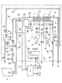
この浴室暖房機付き給湯装置は、図1に示すように、浴槽1や図外の給湯栓に給湯するための給湯手段としての給湯用動作部Aと、浴室内を暖房したり乾燥したりするための浴室暖房乾燥機2に給湯するための暖房用動作部Bとを備え、かつ、浴槽1内の湯水を追焚きするための追焚き手段としての追焚き用動作部Cを備えていて、これら給湯用動作部A、暖房用動作部B、追焚き用動作部Cが、ひとつの熱源機内に収納されている。
【0013】
前記給湯用動作部Aは、燃焼室内に配設されたガス燃焼式のバーナ3、このバーナ3により加熱される給湯用熱交換器4、バーナ3に燃焼用空気を供給するファン5などからなり、バーナ3には、点火のためのイグナイタや着火を検出するフレームロッドなどが設けられている。
前記給湯用熱交換器4には、一般家庭用の水道管に接続して加熱用の水を供給する給水路6と、加熱後の湯を供給する給湯路7とが接続され、かつ、給水路6と給湯路7とが、給湯用熱交換器4を迂回する状態でバイパス路8を介して互いに接続されている。このバイパス路8には、給湯路7からの湯の量と給水路6からの水の量との混合比率を調整して、所望の温度の湯を得るためのバイパス弁9が設けられ、図外の電動モータによって作動可能に構成されている。
【0014】
前記給水路6には、給湯用熱交換器4への入水温度を検出する入水サーミスタ10と、通水量を検出する水量センサ11とが設けられ、給湯路7には、加熱後の湯の温度を検出する出湯サーミスタ12が設けられていて、さらに、バイパス路8との接続箇所よりも下流側の給湯路7には、バイパス弁9の作動によって混合された後の湯の温度を検出する給湯サーミスタ13が設けられている。
前記給湯用動作部Aのバーナ3には、一般家庭用の燃料ガスが供給されるように構成され、燃料ガスの供給を断続する電磁式断続弁14を有する元ガス供給路15から分岐の給湯用ガス供給路16が接続され、このガス供給路16には、燃料ガスの供給量を調節する電磁比例弁17と、燃料ガスの供給を断続する電磁式断続弁18とが設けられている。
【0015】
前記暖房用動作部Bも、燃焼室内に配設されたガス燃焼式のバーナ19、このバーナ19により加熱される暖房用熱交換器20、バーナ19に燃焼用空気を供給するファン21などからなり、バーナ19には、元ガス供給路15から分岐の暖房用ガス供給路22が接続されて、それに電磁比例弁23と電磁式断続弁24とが設けられ、かつ、イグナイタやフレームロッドも設けられている。
前記暖房用熱交換器20には、暖房用の膨張タンク25内の水を供給する暖房用給水路26と、加熱後の湯を供給する暖房用給湯路27とが接続され、この暖房用給湯路27が、前記浴室暖房乾燥機2内の熱交換器に接続されるとともに、その熱交換器により熱交換された後の湯水が、暖房用戻り路28を介して膨張タンク25内に戻されるように構成されている。
【0016】
前記バーナ19の燃焼によって暖房用熱交換器20で加熱された後の湯は、前記追焚き用動作部Cの熱源としても利用され、そのため、前記暖房用給湯路27と暖房用戻り路28とは、浴室暖房乾燥機2を迂回する状態で追焚きバイパス路29を介して互いに接続され、その追焚きバイパス路29には、浴槽1内の湯水を追焚きするための追焚き用熱交換器30と、ヒータによる加熱で開弁する熱動弁31とが設けられている。
前記暖房用給水路26には、膨張タンク25内の水を吸引して暖房用熱交換器20に供給するとともに、加熱後の湯を浴室暖房乾燥機2や追焚き用熱交換器30に供給するための循環ポンプ32が設けられ、暖房用給湯路27には、加熱後の湯の温度を検出する暖房サーミスタ33が設けられている。
【0017】
前記追焚き用動作部Cは、浴槽1内の湯水を追焚き用熱交換器30に供給し、この追焚き用熱交換器30で加熱された後の湯を浴槽1内に戻す追焚き循環路34や追焚き用熱交換器30などからなり、前記追焚き循環路34が、風呂アダプタ35を介して浴槽1に接続されている。
この追焚き循環路34は、浴槽1内の湯水を追焚き用熱交換器30にまで供給する風呂戻り路36と、加熱後の湯を浴槽1にまで供給する風呂往き路37とからなり、風呂戻り路36側には、浴槽1内の湯水を循環されるための風呂循環ポンプ38が設けられ、かつ、この風呂循環ポンプ38と浴槽1との間の風呂戻り路36には、浴槽1側から順に、浴槽1内の湯水の温度を検出する風呂サーミスタ39、水流スイッチ40、浴槽1内の湯水の水位を検出する水位センサ41とが設けられている。
【0018】
前記風呂循環ポンプ38と追焚き用熱交換器30との間の風呂戻り路36には、前記給湯サーミスタ13より下流側の給湯路7から分岐された湯張り路42が接続され、給湯用動作部Aからの湯を浴槽1内に供給可能に構成され、その湯張り路42には、上流側から順に、風呂電磁弁43、逆止弁付き大気開放式のホッパ44、逆止弁45とが設けられている。
前記ホッパ44と逆止弁45とは、浴槽1内の湯水が湯張り路42を介して給湯路7側に逆流するのを防止するためのもので、例え逆止弁45が故障して浴槽1内の湯水が逆流しても、ホッパ44によって逆流が遮断され、かつ、逆流した湯水がホッパ44内に貯められるように構成されている。このホッパ44には、貯められた湯水を浴槽1内に戻すための排水電磁弁46付きの戻し路47が接続され、この戻し路47が水位センサ41と風呂循環ポンプ38との間の風呂戻り路36に接続されるとともに、ホッパ44内の湯水をオーバーフローさせるための排水路48も設けられている。
【0019】
前記給湯用動作部A、暖房用動作部B、追焚き用動作部C、ならびに、浴室暖房乾燥器2などの作動は、全てマイクロコンピュータを主要部とする制御部Hにより制御されるように構成されている。
この制御部Hは、図3に示すように、給湯用動作部A、暖房用動作部B、および、追焚き用動作部Cの作動を制御する風呂制御手段としての熱源機用制御部H1と、浴室暖房乾燥機2の作動を制御する暖房制御手段としての暖房用制御部H2とならなり、熱源機用制御部H1は熱源機内に、暖房用制御部H2は浴室暖房乾燥機2内にそれぞれ収納されていて、両者は通信制御部49,50を介して互いに通信可能に接続されている。
そして、熱源機用制御部H1側の通信制御部49には、メインリモコンR1と風呂リモコンR2とが、暖房用制御部H2側の通信制御部50には、暖房用リモコンR3がそれぞれ通信可能に接続されている。
【0020】
前記メインリモコンR1は、通常、台所などに設置されるもので、このメインリモコンR1には、運転スイッチ51、一般給湯運転時の給湯温度を設定する温度設定スイッチ52、浴槽1への給湯開始手段としての湯張りスイッチ53などが設けられている。
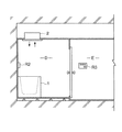
風呂リモコンR2は、図2に示すように、浴室D内の浴槽1の近くに設置されるもので、メインリモコンR1と同様に、運転スイッチ54、湯張りスイッチ55が設けられ、キープ運転指示手段としてのキープ運転スイッチ56、湯張り温度やキープ運転時における湯の温度を設定する温度設定スイッチ57なども設けられている。
暖房用リモコンR3は、浴室Dに隣接する脱衣室E内に設置され、暖房開始手段としての暖房スイッチ58、乾燥スイッチ59、暖房停止手段としての停止スイッチ60、キープ運転指示手段としてのキープ運転スイッチ61などが設けられている。
【0021】
この浴室暖房機付き給湯装置の作動について説明すると、メインリモコンR1の運転スイッチ51か風呂リモコンR2の運転スイッチ54を入れることで作動可能な状態となり、この状態で図外の給湯栓を開けると、給湯用動作部Aが作動して一般給湯運転が実行される。
この一般給湯運転においては、給水路6内を設定量以上の水が流通したことを水量センサ11が検出して、ファン5を回転駆動し、元ガス供給路15の電磁式断続弁14と給湯用ガス供給路16の電磁式断続弁18とを開弁し、かつ、電磁比例弁17の開度を調整して、イグナイタによりバーナ3に点火する。このバーナ3の燃焼により、給湯用熱交換器4によって加熱された後の湯は、バイパス弁9によりバイパス路8からの水と混合され、メインリモコンR1の温度設定スイッチ52により設定された温度に調整されて給湯栓から吐出される。
【0022】
作動可能な状態でメインリモコンR1の湯張りスイッチ53か風呂リモコンR2の湯張りスイッチ55を入れると、風呂電磁弁43が開弁するとともに、給湯用動作部Aが作動して浴槽1内への湯張り運転が実行される。
この湯張り運転においても、先の一般給湯運転と同様に、熱交換器4によって加熱された湯が、バイパス路8からの水と混合され、風呂リモコンR2の温度設定スイッチ57により設定された温度に調整されて、湯張り路42、ならびに、風呂戻り路36と風呂往き路37とを介して風呂アダプタ35から浴槽1内に供給される。浴槽1内に設定量の湯が供給されると、水位センサ41の検出に基づいて風呂電磁弁43が閉弁し、両電磁式断続弁14,18や電磁比例弁17も閉弁してバーナ3の燃焼が停止し、一定時間経過後にファン5も停止される。
【0023】
その後、風呂循環ポンプ38が駆動して風呂サーミスタ39が浴槽1内の湯水の温度を検出し、その検出温度が風呂リモコンR2の温度設定スイッチ57による設定温度に達していれば、風呂循環ポンプ38が停止して、温度設定スイッチ57により設定した適温と水位センサ41での適量による湯張りが終了する。
設定温度に達していなければ、追焚き用動作部Bが作動して追焚き運転が実行される。この追焚き運転においては、熱動弁31が開弁し、循環ポンプ32とファン21とが回転駆動し、かつ、元ガス供給路15の電磁式断続弁14と暖房用ガス供給路22の電磁式断続弁24とが開弁するとともに、電磁比例弁23の開度調整の基にバーナ19が燃焼される。バーナ19の燃焼により加熱された後の湯と浴槽1内の湯水とが、追焚き用熱交換器30で熱交換され、風呂サーミスタ39による検出温度が設定温度に達した時点で、風呂循環ポンプ38が停止し、バーナ19の燃焼も停止して、適温適量湯張りが終了する。
【0024】
この適温適量湯張りが終了すると、引き続いて自動的に適温適量キープ運転が実行されて、浴槽1内の湯が適温と適量に維持される。
この適温適量キープ運転は、予め設定された時間経過毎に自動的に繰り返され、まず、水位センサ41によって浴槽1内の湯量が適量に維持されているか否かを検出し、湯量が不足していると、足し湯運転が実行される。この足し湯運転は、上述の湯張り運転と同じ作動により、温度設定スイッチ57により設定された温度の湯が浴槽1内に供給され、浴槽1内の湯量が適量にキープされる。その後、風呂循環ポンプ38が駆動して風呂サーミスタ39が浴槽1内の湯水の温度を検出し、その検出温度が温度設定スイッチ57による設定温度に達していれば、風呂循環ポンプ38が停止し、達していなければ、上述の追焚き運転と同じ作動によって追焚きされ、風呂サーミスタ39による検出温度が設定温度に達した時点で、風呂循環ポンプ38やバーナ19の燃焼が停止し、浴槽1内の湯の温度が適温にキープされる。
【0025】
この適温適量キープ運転は、図4のフローチャートに示すように、予め設定された時間経過毎に自動的に開始して繰り返されるのであるが、暖房用リモコンR3の暖房スイッチ58により後述する暖房運転が実行され、かつ、その暖房運転が自動的に停止されると、設定時間が経過していなくとも開始される。また、暖房運転中であっても、暖房用リモコンR3の停止スイッチ60を入れると、暖房運転が停止するので、この暖房運転の停止に伴って適温適量キープ運転が開始される。
また、暖房運転中であっても、風呂リモコンR2のキープ運転スイッチ56か暖房用リモコンR3のキープ運転スイッチ61を入れると、浴室暖房乾燥機2による暖房運転と並行して適温適量キープ運転が開始される。
なお、このようなキープ運転開始の判断は、キープ運転中でない場合にのみ行われ、キープ運転中の場合には、このような判断を行うことなく、浴槽1内の湯が適温かつ適量になるまでキープ運転を実行する。
【0026】
この暖房運転においては、暖房用リモコンR3の暖房スイッチ58を入れることで、暖房用動作部Bが作動して浴室D内を暖房する。
この暖房運転では、熱動弁31が閉弁したままとなり、バーナ19の燃焼で暖房用熱交換器20によって加熱された後の湯が、暖房用給湯路27を介して浴室暖房乾燥機2内の熱交換器にまで送られる。この浴室暖房乾燥機2には、ファンやダンパが内装されていて、そのファンにより浴室D内の空気が吸引されて浴室暖房乾燥機2の熱交換器で加熱され、加熱後の温風が浴室D内に排出されて暖房運転が実行され、図外タイマーの作動によって予め設定された時間経過後に、バーナ19の燃焼が停止され、ファンも停止されて自動的に停止する。
この浴室暖房乾燥機2の作動時間については、タイマーにより自由に設定変更できるように構成され、また、暖房運転中であっても、暖房用リモコンR3の停止スイッチ60を入れることで、暖房運転を停止させることができる。
【0027】
この暖房運転と同じ作動により、浴室暖房乾燥機2を利用して浴室D内の洗濯物を乾燥させることもできる。すなわち、暖房用リモコンR3の乾燥スイッチ59を入れると、先の暖房運転と同じ作動によって浴室D内の温度が上昇する。この乾燥運転においては、ダンパの開度調整によって浴室D内から吸引した空気の一部を湿気と共に浴室D外の放出するように構成されているので、浴室D内に干した洗濯物を短時間のうちに乾燥させることができる。
この乾燥運転の作動時間についても、タイマーによって自由に設定変更でき、また、停止スイッチ60を入れることで、乾燥運転中であっても、その乾燥運転を停止させることができる。
【0029】
〔別実施形態〕
先の実施形態においては、給湯用動作部Aの作動によって、浴槽1内に設定温度の湯を供給して湯張りしたり足し湯する構成のものを示したが、浴槽1内に設定温度以下の低温の湯や水を供給し、その後、追焚き用動作部Cを作動させて浴槽1内の湯を設定温度にまで焚き上げる構成のものや、足し湯の際に低温の湯や水を供給して追焚きする構成のものにも適用することができ、このように低温の湯や水を供給するものを湯水供給手段と称する。
さらに、暖房用動作部Bや追焚き用動作部Cについても種々変更が可能であり、例えば、追焚き用熱交換器30をバーナによって直接加熱するように構成したり、あるいは、浴室暖房乾燥機2に代えて、暖房運転のみ可能な浴室暖房機を用いて実施することもできる。
【0030】
その他、制御部Hを熱源機側に収納の熱源機用制御部H1と浴室暖房乾燥機2側に収納の暖房用制御部H2とから構成し、両者を通信可能に接続したものを示したが、この熱源機用制御部H1と暖房用制御部H2とをひとつの制御部Hで構成し、その制御部Hを熱源機側に収納して実施することもできる。
【0031】
【図面の簡単な説明】
【図1】 浴室暖房機付き給湯装置の概略構成図
【図2】 浴室と脱衣室との断面図
【図3】 制御部のブロック図
【図4】 適温適量キープ運転の作動を示すフローチャート
【符号の説明】
1 浴槽
2 浴室暖房機
6 給水路
53,55 給湯開始手段
58 暖房開始手段
60 暖房停止手段
61 キープ運転指示手段
A 湯水供給手段としての給湯手段
C 追焚き手段
D 浴室
H1 風呂制御手段
H2 暖房制御手段
R3 暖房用リモコン[0001]
BACKGROUND OF THE INVENTION
The present invention includes a bathroom heater that heats the inside of a bathroom provided with a bathtub, a heating control means that controls the operation of the bathroom heater, a reheating means that tracks hot water in the bathtub, The present invention relates to a hot water supply apparatus with a bathroom heater, comprising bath control means for controlling the operation of the chasing means so that the temperature of the hot water becomes a set temperature and executing an appropriate temperature keeping operation.
[0002]
[Prior art]
In such a hot water supply apparatus with a bathroom heater, conventionally, the operation of the bathroom heater has been controlled independently by the heating control means, and the operation of the reheating means has been independently controlled by the bath control means. The optimum temperature keeping operation by the control means is configured to be started and executed every time elapses set in advance.
[0003]
[Problems to be solved by the invention]
Thus, in the past, the optimum temperature keeping operation was started at every set time regardless of the actual bathing time, so that the hot water temperature in the bathtub is not necessarily maintained at the appropriate temperature during bathing. However, there is a case where the hot water temperature is considerably lower than the optimum temperature, and there is room for improvement in this respect.
[0004]
The present invention pays attention to such a conventional problem, and in a hot water supply apparatus equipped with a bathroom heater, normally, the bathroom heater is operated before bathing to preheat the interior of the bathroom, The focus is on bathing after the bathroom heater is stopped, and the purpose is to use the bathroom heater effectively, and as much as possible, hot water supply with a bathroom heater that can be bathed immediately after the optimal temperature keep operation is completed. In providing equipment.
[0005]
[Means for Solving the Problems]
In order to achieve this object, according to the first aspect of the present invention, the heating control means for controlling the operation of the bathroom heater switches the heating means as the bathroom heater is switched from the operating state to the stopped state. The bath control means that controls the operation starts the appropriate temperature keeping operation, so that the bath water is kept at a temperature suitable for bathing when bathing by waiting for the bath heater to stop operating. Therefore, it is possible to avoid bathing at a low hot water temperature as much as possible and perform bathing at an optimal hot water temperature.
[0006]
According to the second aspect of the present invention, the heating control means is provided with a heating start means for instructing the heating control means to start the heating operation. When the heating start means is instructed to start the operation, the heating control means Since it is activated and stopped for a set time, by setting the operating time of the bathroom heater in advance, it can be stopped after the inside of the bathroom is heated to an appropriate temperature, and therefore the operation of the bathroom heater is stopped. It is possible to bathe at an appropriate temperature under appropriate temperature and heating by waiting for the bath.
In addition, there is provided a heating stop means for instructing to stop the heating operation. If there is an instruction to stop the operation by the heating stop means, even if the bathroom heater is in operation, the operation of the bathroom heater is stopped to keep the appropriate temperature. Since the operation is started, bathing at the optimum hot water temperature can be performed as required even before the interior of the bathroom is heated to an appropriate temperature.
[0007]
According to the third aspect of the present invention, the heating remote controller for instructing a control command is provided to the heating control means, the heating remote controller is provided with the heating start means and the heating stop means, and the start of the appropriate temperature keep operation is instructed. Therefore, it is possible to instruct the start of the heating operation or the start of the appropriate temperature keep operation by operating the heating remote controller, for example, a dressing room adjacent to the bathroom, etc. It can be used very conveniently and rationally, such as by instructing the start of heating operation and appropriate temperature keeping operation before undressing, making it possible to perform appropriate temperature bathing under appropriate temperature heating at the time of bathing. it can.
[0008]
According to the invention described in
[0009]
According to the fifth aspect of the present invention, the hot water supply means for supplying water to the bathtub by heating water from the water supply channel is provided, and when there is an instruction to start hot water supply by the hot water supply start means for instructing the start of hot water supply operation, Since the means is to execute a hot water filling operation at an appropriate temperature to supply a set amount of hot water at a set temperature in the bathtub, the hot water operation at an appropriate temperature and an appropriate amount is also performed in addition to the above-mentioned appropriate temperature keeping operation and the appropriate temperature appropriate amount keeping operation. This is possible and is very convenient for actual use.
[0010]
According to the sixth aspect of the present invention, the bath control means performs the proper temperature keep operation every time the set time elapses after the hot water filling operation is completed, so the optimum temperature keep is performed regardless of the operation of the bathroom heater. Operation and appropriate temperature and appropriate amount keep operation will be executed, and even if you forget to start the bathroom heater operation and keep operation instructions etc., the hot water in the bathtub will be maintained at an appropriate temperature and appropriate amount to some extent become.
[0011]
According to the invention described in
[0012]
DETAILED DESCRIPTION OF THE INVENTION
An embodiment of a hot water supply apparatus with a bathroom heater according to the present invention will be described with reference to the drawings.
As shown in FIG. 1, this hot water supply apparatus with a bathroom heater heats or dries the hot water supply operation part A as hot water supply means for supplying hot water to a bathtub 1 or a hot water tap outside the figure. A heating operation unit B for supplying hot water to the bathroom heater /
[0013]
The hot water supply operation unit A includes a gas combustion type burner 3 disposed in a combustion chamber, a hot water
The hot water
[0014]
The
The burner 3 of the hot water supply operation part A is configured to be supplied with fuel gas for general households, and is branched from a source
[0015]
The heating operation unit B also includes a
The
[0016]
The hot water heated by the
The heating
[0017]
The reheating operation unit C supplies hot water in the bathtub 1 to the reheating
The
[0018]
A hot
The
[0019]
The operations of the hot water supply operation unit A, the heating operation unit B, the reheating operation unit C, and the
As shown in FIG. 3, the control unit H includes a heat source machine control unit H1 as a bath control means for controlling the operation of the hot water operation unit A, the heating operation unit B, and the reheating operation unit C. The heating control unit H2 serves as a heating control means for controlling the operation of the
Then, the main remote controller R1 and the bath remote controller R2 can communicate with the
[0020]
The main remote controller R1 is usually installed in a kitchen or the like. The main remote controller R1 includes an
As shown in FIG. 2, the bath remote controller R2 is installed near the bathtub 1 in the bathroom D. Like the main remote controller R1, the bath remote controller R2 is provided with an
The heating remote controller R3 is installed in a dressing room E adjacent to the bathroom D, and includes a
[0021]
The operation of the hot water supply device with a bathroom heater will be described. When the
In this general hot water supply operation, the water amount sensor 11 detects that a predetermined amount or more of water has circulated in the
[0022]
When the hot
In this hot water filling operation, similarly to the general hot water supply operation, the hot water heated by the
[0023]
Thereafter, the
If the set temperature has not been reached, the chasing operation section B is activated and chasing operation is executed. In this reheating operation, the
[0024]
When this proper temperature and proper amount of hot water filling is completed, the proper temperature and appropriate amount keep operation is automatically performed, and the hot water in the bathtub 1 is maintained at the appropriate temperature and the appropriate amount.
This appropriate temperature / appropriate amount keeping operation is automatically repeated every time a preset time elapses. First, the
[0025]
As shown in the flowchart of FIG. 4, the appropriate temperature and appropriate amount keep operation is automatically started and repeated every time a preset time elapses. However, the heating operation described later is performed by the
Even during the heating operation, if the keep
Such a determination of the start of the keep operation is made only when the keep operation is not being performed. When the keep operation is being performed, the hot water in the bathtub 1 becomes an appropriate temperature and an appropriate amount without making such a determination. Keep operation until.
[0026]
In this heating operation, the heating operation unit B is activated to heat the bathroom D by turning on the
In this heating operation, the heat operated
About the operating time of this
[0027]
By the same operation as this heating operation, the laundry in the bathroom D can be dried using the
The operating time of the drying operation can be freely changed by a timer, and the drying operation can be stopped even during the drying operation by turning on the
[0029]
[Another embodiment]
In the previous embodiment, the hot water supply operation unit A is operated to supply hot water having a set temperature into the bathtub 1 to fill or add hot water. Supply low-temperature hot water or water, and then operate the chasing operation unit C to raise the hot water in the bathtub 1 to the set temperature, or add low-temperature hot water or water when adding hot water The present invention can also be applied to a structure for supplying and chasing, and such a supply of low-temperature hot water or water is referred to as hot water supply means.
Further, the heating operation unit B and the heating operation unit C can be variously modified. For example, the
[0030]
In addition, although the control part H was comprised from the heat source machine control part H1 accommodated in the heat source machine side, and the heating control part H2 accommodated in the
[0031]
[Brief description of the drawings]
[Fig. 1] Schematic configuration diagram of a hot-water supply device with a bathroom heater [Fig. 2] Cross-sectional view of a bathroom and a dressing room [Fig. 3] Block diagram of a control unit [Fig. Explanation of]
DESCRIPTION OF SYMBOLS 1
Claims (7)
前記風呂制御手段が、前記適温キープ運転を設定時間毎に実行しているときに、前記暖房制御手段が前記浴室暖房機を作動状態から停止状態に切り換えるに伴って、前記設定時間が経過していなくとも、前記適温キープ運転を開始するように構成されている浴室暖房機付き給湯装置。 A bathroom heater that sucks air in the bathroom and heats the bathroom equipped with a bathtub, a heating control means that controls the operation of the bathroom heater, and a circulation path that tracks hot water in the bathtub by a bath circulation pump The temperature of the hot water in the bathtub detected by a bath thermistor provided in the chasing circulation path by driving the bath circulation pump by chasing the chasing heat exchanger through There reheating and does not reach the set temperature, and a bath control means for executing each set time the appropriate temperature keeping operation for controlling the operation of said reheating means to stop the reheating it reaches the set temperature A water heater with a bathroom heater,
The bath control means, when running the appropriate temperature keep driving for each set time, said heating control means with the switch the prior Symbol bathroom heater from the operating state to the stopped state, the set time has elapsed It need not be, bathroom heater equipped with a water heater that is configured to initiate the appropriate temperature keeping operation.
Priority Applications (1)
| Application Number | Priority Date | Filing Date | Title |
|---|---|---|---|
| JP07383996A JP3751069B2 (en) | 1996-03-28 | 1996-03-28 | Water heater with bathroom heater |
Applications Claiming Priority (1)
| Application Number | Priority Date | Filing Date | Title |
|---|---|---|---|
| JP07383996A JP3751069B2 (en) | 1996-03-28 | 1996-03-28 | Water heater with bathroom heater |
Publications (2)
| Publication Number | Publication Date |
|---|---|
| JPH09264554A JPH09264554A (en) | 1997-10-07 |
| JP3751069B2 true JP3751069B2 (en) | 2006-03-01 |
Family
ID=13529719
Family Applications (1)
| Application Number | Title | Priority Date | Filing Date |
|---|---|---|---|
| JP07383996A Expired - Fee Related JP3751069B2 (en) | 1996-03-28 | 1996-03-28 | Water heater with bathroom heater |
Country Status (1)
| Country | Link |
|---|---|
| JP (1) | JP3751069B2 (en) |
Families Citing this family (4)
| Publication number | Priority date | Publication date | Assignee | Title |
|---|---|---|---|---|
| JP4006754B2 (en) * | 2002-12-20 | 2007-11-14 | 株式会社日立ハウステック | Bath kettle with hot water supply with bathroom heating function |
| JP2007064577A (en) * | 2005-09-01 | 2007-03-15 | Noritz Corp | Heat source machine |
| JP5385649B2 (en) * | 2009-03-23 | 2014-01-08 | 大阪瓦斯株式会社 | Bathroom heating equipment |
| JP5567947B2 (en) * | 2010-09-02 | 2014-08-06 | 株式会社ガスター | Heat source equipment |
-
1996
- 1996-03-28 JP JP07383996A patent/JP3751069B2/en not_active Expired - Fee Related
Also Published As
| Publication number | Publication date |
|---|---|
| JPH09264554A (en) | 1997-10-07 |
Similar Documents
| Publication | Publication Date | Title |
|---|---|---|
| JP3751069B2 (en) | Water heater with bathroom heater | |
| JP3773297B2 (en) | Bath facilities | |
| JP5385649B2 (en) | Bathroom heating equipment | |
| JP3744586B2 (en) | Bath facilities | |
| JP4050426B2 (en) | Freezing prevention device | |
| JP3676062B2 (en) | Hot water heater | |
| JP4002371B2 (en) | Bath device with water heater | |
| JPH09273761A (en) | Heat-feeding system | |
| JP3195768B2 (en) | Bath controller | |
| JP3417184B2 (en) | Combustion equipment | |
| KR200147551Y1 (en) | The water supplies device of gas furnace | |
| JP3651648B2 (en) | Control method for bath water heater and control device therefor | |
| JPH09264576A (en) | Bathroom ventilation device | |
| JP4215337B2 (en) | Heat supply system | |
| KR930010243B1 (en) | Combustion control method for gas boiler | |
| JP3544299B2 (en) | Water heater with reheating function | |
| JP2001311550A (en) | Bath hot water supplying device | |
| JP3121294B2 (en) | Bath reheating device | |
| JPH01277137A (en) | Temperature control device in hot water-circulating heater | |
| JPH0531453Y2 (en) | ||
| JPH0468226A (en) | Hot water heater device | |
| JPH11281149A (en) | Reheating apparatus for bathtub water | |
| JP3897426B2 (en) | Heat source equipment | |
| JP3880674B2 (en) | Solar water heater connection type bath pot device | |
| JPH0914679A (en) | Hot water supplier |
Legal Events
| Date | Code | Title | Description |
|---|---|---|---|
| A131 | Notification of reasons for refusal |
Free format text: JAPANESE INTERMEDIATE CODE: A131 Effective date: 20050908 |
|
| A521 | Written amendment |
Free format text: JAPANESE INTERMEDIATE CODE: A523 Effective date: 20051102 |
|
| TRDD | Decision of grant or rejection written | ||
| A01 | Written decision to grant a patent or to grant a registration (utility model) |
Free format text: JAPANESE INTERMEDIATE CODE: A01 Effective date: 20051124 |
|
| A61 | First payment of annual fees (during grant procedure) |
Free format text: JAPANESE INTERMEDIATE CODE: A61 Effective date: 20051206 |
|
| R150 | Certificate of patent or registration of utility model |
Free format text: JAPANESE INTERMEDIATE CODE: R150 |
|
| LAPS | Cancellation because of no payment of annual fees |