JP3750365B2 - Vehicle drive device - Google Patents
Vehicle drive device Download PDFInfo
- Publication number
- JP3750365B2 JP3750365B2 JP25312298A JP25312298A JP3750365B2 JP 3750365 B2 JP3750365 B2 JP 3750365B2 JP 25312298 A JP25312298 A JP 25312298A JP 25312298 A JP25312298 A JP 25312298A JP 3750365 B2 JP3750365 B2 JP 3750365B2
- Authority
- JP
- Japan
- Prior art keywords
- engine
- motor
- input shaft
- generator
- torque converter
- Prior art date
- Legal status (The legal status is an assumption and is not a legal conclusion. Google has not performed a legal analysis and makes no representation as to the accuracy of the status listed.)
- Expired - Fee Related
Links
- 230000005540 biological transmission Effects 0.000 claims description 86
- 230000002093 peripheral effect Effects 0.000 claims description 44
- 239000012530 fluid Substances 0.000 claims description 35
- 230000007246 mechanism Effects 0.000 description 21
- 238000005192 partition Methods 0.000 description 13
- 230000002441 reversible effect Effects 0.000 description 10
- 238000003466 welding Methods 0.000 description 10
- 230000004323 axial length Effects 0.000 description 8
- 230000010349 pulsation Effects 0.000 description 7
- 238000002485 combustion reaction Methods 0.000 description 6
- 238000010586 diagram Methods 0.000 description 6
- 239000000446 fuel Substances 0.000 description 6
- 230000009471 action Effects 0.000 description 4
- 230000033001 locomotion Effects 0.000 description 4
- XEEYBQQBJWHFJM-UHFFFAOYSA-N Iron Chemical group [Fe] XEEYBQQBJWHFJM-UHFFFAOYSA-N 0.000 description 3
- 230000001133 acceleration Effects 0.000 description 2
- 239000003054 catalyst Substances 0.000 description 2
- 230000001276 controlling effect Effects 0.000 description 2
- 230000008878 coupling Effects 0.000 description 2
- 238000010168 coupling process Methods 0.000 description 2
- 238000005859 coupling reaction Methods 0.000 description 2
- 238000013016 damping Methods 0.000 description 2
- 239000003502 gasoline Substances 0.000 description 2
- 238000002347 injection Methods 0.000 description 2
- 239000007924 injection Substances 0.000 description 2
- 238000004519 manufacturing process Methods 0.000 description 2
- VNWKTOKETHGBQD-UHFFFAOYSA-N methane Chemical compound C VNWKTOKETHGBQD-UHFFFAOYSA-N 0.000 description 2
- 230000007935 neutral effect Effects 0.000 description 2
- 238000007789 sealing Methods 0.000 description 2
- 230000002238 attenuated effect Effects 0.000 description 1
- 230000008901 benefit Effects 0.000 description 1
- 239000003638 chemical reducing agent Substances 0.000 description 1
- 230000008602 contraction Effects 0.000 description 1
- 238000006073 displacement reaction Methods 0.000 description 1
- 230000000694 effects Effects 0.000 description 1
- 239000007789 gas Substances 0.000 description 1
- 230000001788 irregular Effects 0.000 description 1
- 238000005304 joining Methods 0.000 description 1
- 239000003949 liquefied natural gas Substances 0.000 description 1
- 239000003915 liquefied petroleum gas Substances 0.000 description 1
- 238000000034 method Methods 0.000 description 1
- 238000010248 power generation Methods 0.000 description 1
- 238000000746 purification Methods 0.000 description 1
- 230000009467 reduction Effects 0.000 description 1
- 230000008929 regeneration Effects 0.000 description 1
- 238000011069 regeneration method Methods 0.000 description 1
- 230000001105 regulatory effect Effects 0.000 description 1
- 238000005096 rolling process Methods 0.000 description 1
- 230000006641 stabilisation Effects 0.000 description 1
- 238000011105 stabilization Methods 0.000 description 1
- 239000007858 starting material Substances 0.000 description 1
- 230000001360 synchronised effect Effects 0.000 description 1
- XLYOFNOQVPJJNP-UHFFFAOYSA-N water Substances O XLYOFNOQVPJJNP-UHFFFAOYSA-N 0.000 description 1
Images


Classifications
-
- Y—GENERAL TAGGING OF NEW TECHNOLOGICAL DEVELOPMENTS; GENERAL TAGGING OF CROSS-SECTIONAL TECHNOLOGIES SPANNING OVER SEVERAL SECTIONS OF THE IPC; TECHNICAL SUBJECTS COVERED BY FORMER USPC CROSS-REFERENCE ART COLLECTIONS [XRACs] AND DIGESTS
- Y02—TECHNOLOGIES OR APPLICATIONS FOR MITIGATION OR ADAPTATION AGAINST CLIMATE CHANGE
- Y02T—CLIMATE CHANGE MITIGATION TECHNOLOGIES RELATED TO TRANSPORTATION
- Y02T10/00—Road transport of goods or passengers
- Y02T10/60—Other road transportation technologies with climate change mitigation effect
- Y02T10/62—Hybrid vehicles
Landscapes
- Electric Propulsion And Braking For Vehicles (AREA)
- Arrangement Of Transmissions (AREA)
- Hybrid Electric Vehicles (AREA)
Description
【0001】
【発明の属する技術分野】
この発明は、内燃機関と電動機などの少なくとも二種類の駆動力源を備えた車両用駆動装置に関し、特にこれらの駆動力源から出力された動力をトルクコンバータなどの流体伝動装置を介して出力するように構成された駆動装置に関するものである。
【0002】
【従来の技術】
従来、自動車などの車両の駆動力源として一般に使用されている内燃機関(エンジン)に加えて、第2の駆動力源として電動機(モータ)を搭載した車両が開発されている。この種の車両では、電動機の出力する動力が、車両の走行のためには必ずしも充分ではないが、電動機の出力の制御性がよいこと、電動機によってエネルギの回生をおこなうことができること、電動機は排ガスを生じないことなどの利点を生かして電動機を使用するように構成している。例えば、発進時などに大きいトルクが必要な場合には、電動機を内燃機関の補助的な駆動力源として動作させ、また減速時には、電動機を発電機として機能させてエネルギの回生をおこない、さらにはエンジンの出力トルクの脈動とは180度位相がずれて脈動するトルクを電動機によって出力することにより車両の振動を抑制するなどのことがおこなわれている。
【0003】
また、車両の駆動トルクを必要十分に大きくし、あるいはエンジンが出力する動力によって後進走行を可能にするために、上記の二種類の駆動力源の出力側に変速機を連結し、その変速機と各動力源とを流体伝動装置を介して連結することもおこなわれている。その一例が特開平8−168104号公報に記載されている。
【0004】
この公報に記載された装置は、エンジンの出力するトルクの脈動を電動機によって抑制することを目的としたものであり、そのためにエンジンの出力側にモータ・ジェネレータを配置し、さらにそのモータ・ジェネレータの出力側に、トルクコンバータと変速機とを順に配置して構成されている。
【0005】
ところで、流体伝動装置は、その内部に封入されたオイルなどの流体を、駆動側の回転翼によって螺旋流として流動させ、その駆動側の回転翼と対向して配置された従動側の回転翼にその螺旋流が衝突することにより、従動側回転翼が回転し、このようにして流体を介して動力を伝達するように構成されている。したがって内部にオイルなどの流体を封入する必要があるために、流体伝動装置は、全体として密閉された構造とされる。上記の公報に記載されているトルクコンバータもこの種の密閉構造の装置であり、従来では、内面に多数のブレードを取り付けたポンプシェルの先端側に、全体として椀形を成すフロントカバーを一体に接合して中空容器を形成し、その内部にタービンランナやステータを収容するとともに、フルードを封入して構成されている。そして従来では、このトルクコンバータをエンジンの直後に配置し、エンジンのフライホイールをフロントカバーの正面にボルトによって直接連結している。
【0006】
【発明が解決しようとする課題】
上記の公報に記載された装置は、エンジンの直後に配置されていたトルクコンバータをエンジンから離隔し、そのエンジンとトルクコンバータとの間にモータ・ジェネレータを配置する構成であるから、従来一般のトルクコンバータの構造とは異なる新たな構造を採用する必要がある。すなわち、上記公報に記載されている装置は、エンジンおよびモータ・ジェネレータならびにトルクコンバータ、自動変速機を一直線上に配列する構成であるから、元来、全体としての軸長が長くなる要因があり、したがって従来のトルクコンバータとエンジンとの間にこれらを連結するシャフトなどの連結部材とモータ・ジェネレータとを単に介在させたのでは、全体の軸長が更に長くなり、車載性が悪くなるばかりか、車両の小型軽量化を阻害する要因になる。
【0007】
例えば従来のトルクコンバータは、ポンプシェルとフロントカバーとによって中空の容器を形成した構成であるから、これにモータ・ジェネレータを介してエンジンを連結するとすれば、エンジンのフライホイールに類似したプレートおよびその中心部に設けたシャフトをエンジンとの間に介在させてエンジンとトルクコンバータとを連結することになる。そして、それらの間に更にモータ・ジェネレータを介在させることになるから、全体としての軸長が長くなってしまう。
【0008】
また、これらトルクコンバータやモータ・ジェネレータを連結するための手段としてボルトやスプラインなどの手段を採用するとすれば、機械加工をおこなう部品点数が多くなるうえに、組み付け時の工数が多くなって装置全体としての生産性が悪化する可能性がある。
【0009】
この発明は、上記の事情を背景としてなされたものであり、軸長を短くでき、また生産性の良好な車両用駆動装置を提供することを目的とするものである。
【0010】
【課題を解決するための手段およびその作用】
上記の目的を達成するために、請求項1の発明は、第1駆動力源と、第2駆動力源と、これら第1駆動力源の出力する動力および第2駆動力源の出力する動力が入力される外殻の内部に流体を封入した流体伝動装置とを有する車両用駆動装置において、前記第1駆動力源の出力する動力が伝達されて回転する入力部材に、半径方向に突出した板状の部分を備えたハブ部が形成されるとともに、前記流体伝動装置の外殻の一部が、回転中心側に開口部を形成されたフロントカバーによって形成され、そのフロントカバーの開口部内に前記ハブ部における板状の部分を嵌合させてハブ部にフロントカバーが一体的に固着されてハブ部が前記外殻の一部を形成し、さらにそのハブ部における前記外殻の外側に位置する部分に、前記第2駆動力源の出力側部材が一体的に取り付けられ、さらに前記外殻の他の一部の外周側に前記第2駆動力源のステータの一部が配置されていることを特徴とするものである。
【0011】
また請求項2の発明は、請求項1の構成において、前記入力部材が、前記第1駆動力源の出力部材に連結される入力軸によって構成され、かつ前記ハブ部が、その入力軸における前記流体伝動装置側の端部に一体的に形成されていることを特徴とするものである。
【0012】
したがってこの発明によれば、入力部材が、第1駆動力源から流体伝動装置に対して動力を伝達する部材と、第2駆動力源と流体伝動装置とを連結する部材とを兼ねるうえに、そのハブ部が流体伝動装置の外殻の一部を構成するので、これらの部材の連結部分に必要とするスペースが小さくてよいうえに、部品点数が少なくなり、その結果、装置の全体としての軸長が短くなる。またそのハブ部とフロントカバーとを一体化する手段として溶接などの溶着手段を採用することが可能であるから、流体伝動装置のシール性が確実なものとなる。さらに入力部材のハブ部とフロントカバーと第2駆動力源の出力側部材とを一体に構成しておくことができ、しかもそのための固着部をそれぞれ1箇所、合計2箇所とすることができるので、製造作業性が向上するのみならず工数が低減されて生産性の高いものとすることができる。
【0013】
【発明の実施の形態】
つぎにこの発明を図面を参照して具体的に説明する。図2はこの発明による駆動装置の基本的な構成を示しており、第1駆動力源1と第2駆動力源2とが設けられている。その第1駆動力源1は、燃料の燃焼によって動力を出力する形式の装置であり、ガソリンエンジンやディーゼルエンジンのほかに、液化石油ガスや天然ガスなどのガス燃料を燃焼させるエンジンなどがその例である。この発明は、その第1駆動力源1として出力されるトルクが繰り返し変動(脈動)するエンジンを使用した場合に、特に有効である。なお、以下の説明では、第1駆動力源1をエンジン1と記す。
【0014】
第2駆動力源2は、要は、エンジン1とは異なる種類の駆動力源であり、原理的にはトルクの変動(脈動)を生じさせることなく動力を出力することのできる装置であり、電気的エネルギを回転運動などの運動エネルギに変換して出力することのできる電動機がその例である。特に、この発明は、発電機能(回生機能)のある電動機を使用した場合に、有効である。なお、以下の説明では、第2駆動力源2をモータ・ジェネレータ2と記す。
【0015】
上記のエンジン1にフライホイール3が連結されている。このフライホイール3は、従来のガソリンエンジンやディーゼルエンジンに取り付けられているものと同様に、エンジン1のトルクの変動を抑制するためのものであり、回転慣性モーメントの大きい円板状の部材である。また、このフライホイール3に制振機構(ダンパ)4が連結されている。このダンパ4は、フライホイール3から入力される動力の変動を減衰させて、すなわち振動もしくは脈動の振幅を小さく(平準化)して出力する機構であり、必要に応じて各種の構成のものを使用することができる。一般的には、相対回転可能な入力側の部材と出力側の部材との間に弾性体を介在させ、その弾性体の伸縮によって振動を減衰させる構成のものを使用することができる。なお、このフライホイール3とダンパ4とは、予め一体に組み付けた構成のものを使用することができる。また、フライホイール3は、選択的に採用することのできる部材であって、これを省いてエンジン1とダンパ4とを直接連結してもよい。
【0016】
上記のダンパ4に流体伝動装置5が連結され、その流体伝動装置5の出力側に変速機6が連結されている。この発明で対象とする駆動装置における流体伝動装置5は、要は、流体を介して動力を伝達することのできる構成であればよく、トルクの増幅作用のない装置、あるいはトルクの増幅作用のある装置(トルクコンバータ)のいずれであってもよい。また、流体を介して相互にトルクの伝達をおこなう入力側の部材と出力側の部材とを選択的に直接連結するロックアップクラッチを備えていない流体伝動装置あるいは備えている流体伝動装置のいずれかを使用することができる。なお、以下の説明では、ロックアップクラッチ付きのトルクコンバータ(T/C)5を例に示す。
【0017】
また一方、変速機6は、入力回転数と出力回転数との比(変速比)を適宜に変更することのできる装置であって、有段式の変速機や変速比を連続的に変化させることのできる無段変速機などを採用することができる。また自動変速機と手動変速機とのいずれであってもよい。以下の説明では、変速機6として自動変速機(AT)6を使用した例を示す。
【0018】
前記モータ・ジェネレータ2は、ダンパ4とトルクコンバータ5とを連結している部材、言い換えればトルクコンバータ5の入力側の部材に連結されている。すなわちエンジン1の動力とモータ・ジェネレータ2の動力とをトルクコンバータ5を介して自動変速機6に出力できるように構成されている。なお、モータ・ジェネレータ2として例えば永久磁石型同期モータを使用した場合には、その出力側部材であるロータの回転角度を検出するためのレゾルバ7がモータ・ジェネレータ2と並列に配列される。その場合、レゾルバ7のロータもモータ・ジェネレータ2のロータと同様に、ダンパ4とトルクコンバータ5とを連結している部材もしくはトルクコンバータ5の入力側の部材に連結される。
【0019】
図2に示す構成を更に具体化した構成を図3に部分断面図として示してある。前記トルクコンバータ5を収容しているトランスミッションハウジング10のエンジン1側の端部に、アダプタ11が取り付けられている。このアダプタ11は、トランスミッションハウジング10の開口端とほぼ等しい外径の円筒状の部材であって、トランスミッションハウジング10の端部とエンジン1との間に挟み込んだ状態に固定されている。このアダプタ11の内周面で軸線方向での中間部には、中心部に向けて適宜に屈曲して延びた隔壁部12が一体に形成されている。その隔壁部12には、トルクコンバータ5の中心軸線と軸線を一致させた貫通孔が形成されている。
【0020】
前記アダプタ11の内周側の空間部のうち隔壁部12によって仕切られたエンジン1側の空間部に、エンジン1の出力部材であるクランクシャフト13の先端部が延びており、そのクランクシャフト13の先端部にフライホイール3がボルト14によって固定されている。このフライホイール3の正面(エンジン1とは反対側の面)にダンパ4が取り付けられている。したがってフライホイール3とダンパ4とが、アダプタ11の内周側で隔壁部12によって仕切られたエンジン1側の空間部に収容されている。
【0021】
ダンパ4は、半径方向で外側に延びた平板部を有する中空円板状の第1のプレートとその中心側の部分に対向して取り付けられかつ第1のプレートと共に円周方向に沿う窓孔部を形成する第2のプレートとからなる駆動側部材15と、その駆動側部材15における各プレートの間に相対回転可能に延ばした板状の突出部を円筒状のボス部16の外周側に一体化させ、かつその板状の突出部に前記窓孔部と一致する窓孔部を形成した従動側部材17と、それらの窓孔部に保持されかつ駆動側部材15と従動側部材17とが相対回転することによってこれらの部材15,17によって圧縮されるダンパスプリング18とによって構成されている。そしてその駆動側部材15における半径方向で外側に延びた平板部が、フライホイール3の正面にボルト19によって固定されている。すなわち駆動側部材15がダンパ4の入力側部材となり、かつ従動側部材17がダンパ4の出力側部材となっている。
【0022】
前記隔壁部12の内周側の端部は、軸線方向に延びた比較的短い円筒状に形成され、この円筒状の部分20に軸受21が嵌合させられており、この軸受21は、前記円筒状の部分20の内周面に取り付けた固定用部材であるスナップリング22によって固定されている。そしてこの軸受21の内周側に入力軸23が嵌合させられ、したがってこの入力軸23が軸受21を介して隔壁部12によって回転自在に支持され、また軸線方向に対しては固定されている。
【0023】
この入力軸23の先端部(図3での左側端部)が、前記ダンパ4の内周部にまで延びており、かつ前記ダンパ4における従動側部材17のボス部16に挿入されている。そして、これら入力軸23と従動側部材17とが、それぞれに形成されたスプライン24によって連結されている。また、入力軸23の外周部のうち前記軸受21に隣接する部分に、レゾルバ7のロータ25が嵌合させられており、このロータ25は、キー26によって入力軸23に対して回り止めされるとともに、スナップリング27によって軸線方向に対して固定されている。すなわちこのロータ25の図3での右側の端部が前記軸受21に当接しており、したがってロータ25は軸受21とスナップリング27とによって挟み込まれて固定されている。
【0024】
前記隔壁部12は、図3に示すように、その中間部が軸線方向に二段に屈曲しており、内周側の屈曲部分の内周面には、複数のインロー嵌合部28が円周方向に一定の間隔をあけて形成され、このインロー嵌合部28にレゾルバ7におけるステータ29が嵌合されかつボルト30によって固定されている。より具体的には、そのステータ29は、軸線方向における位置を前記ロータ25と一致させ、そのロータ25の外周面に接近した位置に配置されている。なお、ボルト30がステータ29を貫通している部分は円周方向に沿う長孔となっており、かつボルト30は図3に示すように隔壁部12よりエンジン1側から挿入されて隔壁部12に螺合している。したがってダンパ4を入力軸23に対してスプライン嵌合させるに先立って、ボルト30をゆるめた状態でステータ29を円周方向に回動させることにより、ロータ25に対するステータ29の円周方向での相対位置を調整できるように構成されている。
【0025】
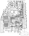
入力軸23の後端部(図3での右側端部)は、隔壁部12における円筒状の部分20の先端近傍にあってその円筒状の部分20より半径方向で外側に延び、その半径方向で外側に延びた部分にハブ部31が形成されている。したがってこのハブ部31は、前記隔壁部12を挟んで前記ダンパ4とは反対側の空間部に収容されており、また、前記円筒状の部分20の外周側で該円筒状部分20と同心円上の位置に配置されている。そしてそのハブ部31には、モータ・ジェネレータ2の出力側部材であるロータ32と、トルクコンバータ5のフロントカバー33とが一体的に連結されている。このハブ部31に対するロータ32とフロントカバー33との取付構造を図1に拡大して示してある。したがってこの入力軸23がこの発明における入力部材に相当している。
【0026】
前記ハブ部31は、軸線方向に所定の長さを有した円筒状の部分であり、これに対してロータ32は、回転中心部に貫通孔を形成した中空円板状の部材の外周部に永久磁石を取り付けたものであって、その円板状部材の貫通孔の部分を、前記ハブ部31における図1および図3での左側端部に嵌合させて溶接などの固定手段によってー体化させることにより、ハブ部31に一体的に取り付けられている。なお、入力軸23が前記軸受21を介して隔壁部12によって軸線方向に位置決めされていることにより、ロータ32も入力軸23と共に軸受21を介して隔壁部12によって軸線方向での位置が決められている。
【0027】
このロータ32の外周側にステータ34が配置されている。このステータ34は、積層鉄心とコイルとからなるものであって、前記アダプタ11の内周面に固定されている。そしてその積層鉄心がロータ32における永久磁石と半径方向で接近して対向しており、これに対してコイルが積層鉄心に対して軸線方向に張り出している。したがってモータ・ジェネレータ2は、コイルが軸線方向に突出し、これに対してロータ32の永久磁石の部分がコイルよりも軸線方向で内側に大きく入り込んでおり、さらに永久磁石を取り付けてある円板状の部分が最も薄くて軸線方向に更に入り込んでいる。前記隔壁部12は、モータ・ジェネレータ2におけるこのような輪郭形状に沿って屈曲している。
【0028】
したがってエンジン1側(図3での左側)に突出しているコイルの部分の内周側に、前記フライホイール3の一部が入り込んでおり、かつ前記ダンパ4が配置されている。すなわちダンパ4およびフライホイール3の一部ならびにステータ34の一部を、半径方向に並べて配置することにより、空間を有効利用して軸長の短縮化が図られている。さらにレゾルバ7におけるロータ25を、モータ・ジェネレータ2のロータ32から分離して入力軸23に取り付けることにより、レゾルバ7をモータ・ジェネレータ2を収容している空間部分から外に出し、かつそのレゾルバ7をモータ・ジェネレータ2におけるロータ32の内周側に配置したので、この点でも半径方向に配列する部材を増やして軸長の短縮化が図られている。また、ステータ34およびロータ32の永久磁石の部分を、その回転中心から可及的に外周側に配置することにより、発生するトルクを大きくしてモータ・ジェネレータ2の小型化が図られている。
【0029】
一方、フロントカバー33は、トルクコンバータ5におけるポンプシェル35と一体化されてトルクコンバータ5の外殻の一部を形成する部材であって、図3に示すような異形断面の円板状の部材である。このフロントカバー33の回転中心部には、図1に示すように、所定半径の開口部33Aが形成されており、その開口部33Aの近傍および半径方向での中間部分は、半径方向に沿う比較的単純な平板形状であり、これに対して外周側の部分は、軸線方向に張り出している前記コイルの内周側を通ってそのコイルの軸線方向の側面に到るように屈曲した形状に成形されている。そしてこの屈曲した外周部の先端部でポンプシェル35の先端部に溶接などの固定手段で一体化され、また開口部33Aを前記ハブ部31の軸線方向での他端部(図1および図3での右端部)に嵌合させるとともに溶接などの固定手段で一体化されている。したがってハブ部31がフロントカバー33と共にトルクコンバータ5の外殻の一部を形成している。また、ロータ32のハブ部31に対する取付部分が、トルクコンバータ5の外殻の外側に位置している。
【0030】
ポンプシェル35は、従来のトルクコンバータのポンプシェルと同様に、回転中心から半径方向に延びた部分が、いわゆる椀形断面に湾曲した形状を成しており、その椀形に湾曲した部分の内面に、ポンプブレードが固定されてポンプインペラを構成している。そしてこのポンプシェル35の他方の端部(図3での右側の端部)は、前記入力軸23と中心軸線を一致させた円筒軸36となっている。そしてこの円筒軸36が油圧ポンプ37のボデー38におけるボス部39の内周側に挿入され、そのボス部39の内周部に挿入したブッシュ40によって軸線方向に移動し得る状態で回転可能に保持されている。なお、このブッシュ40は滑り軸受であり、これに替えて軸線方向への移動を許容できるころがり軸受を使用することもできる。
【0031】
この油圧ポンプボデー38は、トランスミッションハウジング10の内周面に固定されるとともに、その内部にロータ37Aを回転自在に収容しており、前記ポンプシェル35における円筒軸36の先端部がそのロータ37Aに係合している。すなわち入力軸23に伝達された動力によって油圧ポンプ37を駆動するように構成されている。なお、ボス部39の先端部と円筒軸36の外周面との間にオイルシール41が配置されている。したがって前記軸受21をシール構造のものとすることにより、モータ・ジェネレータ2が収容されている空間部が液密状態に維持されている。
【0032】
上記の円筒軸36の内周側に、円筒状の固定軸42が、同一軸線上に配置されている。この固定軸42は、油圧ポンプ37のボデー38に一体化された支持用の軸であって、その先端部がトルクコンバータ5の内部にまで延びている。そしてこの固定軸42の先端部外周に一方向クラッチ43のインナーレースがスプライン嵌合して取り付けられており、またその一方向クラッチ43のアウターレースにステータ35Aが取り付けられている。
【0033】
さらに固定軸42の内周側には変速機入力軸44が挿入され、固定軸42の内周面との間に配置した軸受45によって回転自在に支持されている。この変速機入力軸44の先端部は、前記固定軸42の先端部方向に突出しており、その先端部にハブ46がスプライン嵌合されている。なお、このハブ46と変速機入力軸44との間はオイルシール47によって液密状態に封止されている。
【0034】
ハブ46には、タービンランナ48とロックアップクラッチ49とが連結されている。タービンランナ48は、椀形に湾曲したシェルの内面に複数のブレードを固定した構造であって、前記ポンプインペラとほぼ対称形状を成しており、前記ステータ35Aを挟んでポンプインペラと対向して配置されている。
【0035】
ロックアップクラッチ49は、多板構造のクラッチであって、前記フロントカバー33の内面に対向した位置に設けられている。すなわちフロントカバー33の中間部で半径方向に沿う平板状の部分の正面に対向してクラッチドラム50が配置されている。このクラッチドラム50は、ほぼ有底円筒状を成す部材であって、フロントカバー33の中間部の内面に対向する位置に配置されるとともに、その内周側の端部で前記ハブ46にリベットによって固定・一体化されている。このクラッチドラム50の円筒状を成す外周部の内面に摩擦板51がスプライン嵌合されている。またこの摩擦板51を挟んでフロントカバー33の内面と対向する位置に他の摩擦板52が配置され、この他の摩擦板52は、フロントカバー33の内面に取り付けたリング状のリテーナ53の外周側に嵌合されている。さらにこれらの摩擦板51,52を挟んでフロントカバー33の内面に対向する位置にピストン54が軸線方向に前後動するように配置されている。このピストン54は、環状の板状体であって、その内周部によって前記ハブ46に液密状態を維持して摺動自在に嵌合するとともに、外周部がクラッチドラム50の円筒状部分の内周面に摺接している。
【0036】
上述したフロントカバー33およびポンプシェル35によって区画されている空間部すなわちトルクコンバータ5の内部にはオイル(オートマチックトランスミッションフルード)が充填されており、入力軸23と共にポンプインペラが回転して生じるオイルの螺旋流がタービンランナ48に供給されてタービンランナ48が回転し、その結果、入力軸23から変速機入力軸44に動力が伝達される。したがって入力軸23がトルクコンバータ5の入力側の部材になっている。
【0037】
また、ピストン54の背面側すなわち摩擦板51,52とは反対側の油圧を、正面側すなわち摩擦板51,52側の油圧より高くすることにより、ピストン54が摩擦板51,52をフロントカバー33の内面との間に挟み付け、その結果、フロントカバー33からこれらの摩擦板51,52を介してクラッチドラム50ならびにハブ46および変速機入力軸44に動力が伝達される。すなわちロックアップクラッチ49が係合することにより、このロックアップクラッチ49を介して入力軸23から変速機入力軸44に直接動力が伝達される。
【0038】
このようにロックアップクラッチ49が設けられている位置は、フロントカバー33の中間部であって半径方向に沿う平板部分に対向する位置であり、これは、フロントカバー33が前述したように屈曲していることにより、モータ・ジェネレータ2におけるステータ34の内周側、より正確にはステータ34におけるコイルの内周側の位置である。言い換えれば、流体伝動装置であるトルクコンバータ5の外周側の一部が半径方向で内側に窪まされて凹部を形成しており、このようにして外径を縮小した部分が、モータ・ジェネレータ2におけるステータ34の内側に入り込まされている。言い換えれば、トルクコンバータ5の外周側の一部に凹部が形成され、その凹部にステータ34のコイルの一部が配置されている。
【0039】
このような構成が可能になったのは、以下の理由による。ステータ34の内周側に入り込んでいるトルクコンバータ5の一部は、ロックアップクラッチ49であり、ロックアップクラッチ49が多板構造とされてその外径寸法を小さくしても必要十分な伝達トルク容量を確保できるからである。また、ロックアップクラッチ49が係合すると、トルクコンバータ5に対する入力トルクの変動がそのまま出力側に伝達されるが、図3に示す構成では、入力軸23の入力側にダンパ4が配置されていて、トルクコンバータ5に対する入力トルクの変動が抑制もしくは防止されており、その結果、ロックアップクラッチ49にダンパ機構を設ける必要がなく、そのためにロックアップクラッチ49を小径化できたためである。したがって上記の例では、ロックアップクラッチ49の外径が、タービンランナ48の外径より小さく設定されている。
【0040】
なお、特には符号を付さないが、入力軸23とハブ46との間、ハブ46と一方向クラッチ43との間、一方向クラッチ43と円筒軸36のフランジ部との間には、それぞれスラスト軸受が配置されている。また、上記のトルクコンバータ5におけるステータ35Aの作用およびこれを支持している一方向クラッチ43の作用は、従来のトルクコンバータと同様であるので、その説明は省略する。
【0041】
上述したようにトルクコンバータ5は、フロントカバー33およびポンプシェル35ならびに入力軸23の一部と円筒軸36の一部とによって構成された中空容器の内部にオイルを充填した構造であり、そのオイルの圧力が高くなると、その全体が幾分膨張する。その場合、図3に示す構成では、ポンプシェル35と実質的に一体の入力軸23が前記軸受21によって軸線方向に対しては移動しないように支持され、これに対して円筒軸36がブッシュ40によって支持されているので、トルクコンバータ5の油圧の上昇による変形は、円筒軸36の軸線方向の変位によって吸収される。その結果、モータ・ジェネレータ2におけるロータ32とステータ34との軸線方向での相対位置やレゾルバ7におけるロータ25とステータ29との軸線方向での相対位置にズレが生じることが防止されている。
【0042】
ここで、図3に示す装置の組み付け手順を説明する。トルクコンバータ5は、その全体が密閉構造であり、かつ一端部が油圧ポンプ37によって支持されるから、トルクコンバータ5の全体を予め組み立てた状態で、トランスミッションハウジング10の内部に挿入されて油圧ポンプ37や固定軸42あるいは変速機入力軸44に対して組み付けられる。このトルクコンバータ5と一体の部材は、前述した円筒軸36および入力軸23ならびにロータ32である。一方、アダプタ11には、モータ・ジェネレータ2のステータ34と、レゾルバ7のステータ29と、軸受21とを組み付けておく。その状態で、軸受21の内周側に入力軸23を挿入しつつ、アダプタ11をトランスミッションハウジング10の端面に接合する。その結果、モータ・ジェネレータ2のロータ32の外周側にステータ34が位置決めされ、モータ・ジェネレータ2が正規の状態に組み付けられる。
【0043】
つぎにレゾルバ7のロータ25を入力軸23の外周にはめ込み、キー26によって回り止めするとともに、スナップリング27によって固定する。この状態では、アダプタ11のエンジン1側の端部が開口した状態になっているので、レゾルバ7のステータ29を固定しているボルト30をゆるめて、ステータ29を円周方向に回動させることにより、ロータ25との円周方向での相対位置の調整をおこなうことができる。
【0044】
さらにフライホイール3をエンジン1のクランクシャフト13に取り付けるとともに、そのフライホイール3にダンパ4を固定しておく。そして、上記のようにトランスミッションハウジング10に接合されたアダプタ11を、入力軸23の先端部にダンパ4のボス部16をスプライン嵌合させつつ、エンジン1に連結する。
【0045】
したがって上記の駆動装置を構成している各要素の配列順序は、図4のとおりである。すなわちここに示す例は、エンジン1を車両の前後方向に向けて配置したFR車(フロントエンジン・リヤドライブ車)に適する配置例であり、エンジン1の出力側にモータ・ジェネレータ2が配置され、そのモータ・ジェネレータ2の出力側にトルクコンバータ5を介して自動変速機6が配置されている。この自動変速機6は、後述する歯車変速機部55と油圧制御部56とを備えており、歯車変速機部55から後方側に延びた出力軸57を介して動力を出力するようになっている。また、油圧制御部56は、前記ロックアップクラッチ49の係合・解放の制御および変速制御ならびに摩擦係合装置の係合圧の制御をおこなうためのものであって、複数の電磁バルブや切り換えバルブならびに調圧バルブを備え、電磁バルブを電気的に制御することにより、上記の各制御を実行するように構成されている。なお、この油圧制御部56としては、従来知られている自動変速機用の油圧制御装置を採用することができる。
【0046】
前述したようにモータ・ジェネレータ2は、ダンパ4とトルクコンバータ5とを連結している部材、より具体的には入力軸23に連結されており、したがってモータ・ジェネレータ2を駆動することによりモータ走行をおこない、また反対に入力軸23からモータ・ジェネレータ2に動力を伝達することにより、モータ・ジェネレータ2で発電をおこなってエネルギの回生をおこなう。そのために、モータ・ジェネレータ2には、図5に示すように、インバータ57を介してバッテリ58が接続されている。
【0047】
そのインバータ57は、モータ・ジェネレータ2の制御のために従来使用されているものと同様であって、モータ・ジェネレータ2に対する電流および周波数を制御し、またモータ・ジェネレータ2で発電する際の電流を制御するように構成されている。そして、それらの制御をおこなうためにコントローラ59が設けられている。このコントローラ59は、一例としてマイクロコンピュータを主体とするものであって、エンジン1の始動要求、発進あるいは加速要求、さらには制動要求などに従ってインバータ57およびバッテリ58を制御するように構成されている。
【0048】
その制御の例を挙げると、エンジン1の始動要求があると、バッテリ58からモータ・ジェネレータ2に電流を供給してモータ・ジェネレータ2を駆動し、その動力によってクランクシャフト13を回転させ、同時にエンジン1に燃料を供給してエンジン1を始動する。また発進や加速などのために大きい駆動力が要求された場合には、モータ・ジェネレータ2をバッテリ58の電力で駆動し、エンジン1による動力に加えてモータ・ジェネレータ2による動力をトルクコンバータ5に入力する。さらに制動操作に伴う制動要求があった場合には、モータ・ジェネレータ2を入力軸23から伝達される動力によって回転させて発電をおこなわせ、その電流をバッテリ58に供給して充電する。したがって運動エネルギを電気エネルギに変換するので、これが車両の走行に対しては負荷となり、制動力を得ることができる。なお、バッテリ58がほぼ満杯まで充電されていたり、あるいは温度が上限程度まで高くなっていれば、バッテリ58に対する充電が制限されるので、充電回路を開くなどのことによって充電を中止する。
【0049】
上記のエンジン1やモータ・ジェネレータ2ならびに自動変速機6などの各装置は、車両の状態を示す各種のデータに基づいて制御される。例えば図6に示すように、マイクロコンピュータを主体とする総合制御装置(ECU)60に各種の信号を入力し、その入力された信号に基づく演算結果を制御信号として出力するようになっている。この入力信号の例を挙げれば、ABS(アンチロックブレーキ)コンピュータからの信号、車両安定化制御(VSC:商標)コンピュータからの信号、エンジン回転数NE 、エンジン水温、イグニッションスイッチからの信号、バッテリSOC(State of Charge:充電状態)、ヘッドライトのオン・オフ信号、デフォッガのオン・オフ信号、エアコンのオン・オフ信号、車速信号、自動変速機(AT)油温、シフトポジション、サイドブレーキのオン・オフ信号、フットブレーキのオン・オフ信号、触媒(排気浄化触媒)温度、アクセル開度、カム角センサからの信号、スポーツシフト信号、車両加速度センサからの信号、駆動力源ブレーキ力スイッチからの信号、タービン回転数NT センサからの信号、レゾルバ信号などである。
【0050】
また、出力信号の例を挙げると、点火信号、噴射(燃料の噴射)信号、スタータヘの信号、前記コントローラ59への信号、減速装置への信号、ATソレノイドヘの信号、ATライン圧コントロールソレノイドヘの信号、ABSアクチュエータへの信号、自動停止制御実施インジケータヘの信号、自動停止制御未実施インジケータヘの信号、スポートモードインジケータヘの信号、VSCアクチュエータヘの信号、ATロックアップコントロールバルブヘの信号などである。
【0051】
この発明に係る上記の駆動装置は、基本的には、走行のための動力をエンジン1によって出力し、またエンジン1によって減速し、モータ・ジェネレータ2は走行のための駆動力あるいは制動力を補助するために使用される。したがって前記自動変速機6は後進段を含む複数の変速段を設定することができるように構成されている。その歯車変速機部55の一例を図7に示してある。
【0052】
ここに示す構成では、前進5段・後進1段の変速段を設定するように構成されている。すなわちここに示す自動変速機6は、トルクコンバータ5に続けて副変速部61と、主変速部62とを備えている。その副変速部61は、いわゆるオーバードライブ部であって1組のシングルピニオン型遊星歯車機構63によって構成され、キャリヤ64が前記変速機入力軸44に連結され、またこのキャリヤ64とサンギヤ65との間に一方向クラッチF0 と一体化クラッチC0 とが並列に配置されている。なお、この一方向クラッチF0 はサンギヤ65がキャリヤ64に対して相対的に正回転(変速機入力軸44の回転方向の回転)する場合に係合するようになっている。またサンギヤ65の回転を選択的に止める多板ブレーキB0 が設けられている。そしてこの副変速部61の出力要素であるリングギヤ66が、主変速部62の入力要素である中間軸67に接続されている。
【0053】
したがって副変速部61は、多板クラッチC0 もしくは一方向クラッチF0 が係合した状態では遊星歯車機構63の全体が一体となって回転するため、中間軸67が変速機入力軸44と同速度で回転し、低速段となる。またブレーキB0 を係介させてサンギヤ65の回転を止めた状態では、リングギヤ66が変速機入力軸44に対して増速され正回転し、高速段となる。
【0054】
他方、主変速部62は三組の遊星歯車機構70,80,90を備えており、それらの回転要素が以下のように連結されている。すなわち第1遊星歯車機構70のサンギヤ71と第2遊星歯車機構80のサンギヤ81とが互いに一体的に連結され、また第1遊星歯車機構70のリングギヤ73と第2遊星歯車機構80のキャリヤ82と第3遊星歯車機構90のキャリヤ92との三者が連結され、かつそのキャリヤ92に出力軸57が連結されている。さらに第2遊星歯車機構80のリングギヤ83が第3遊星歯車機構90のサンギヤ91に連結されている。
【0055】
この主変速部62の歯車列では後進段と前進側の四つの変速段とを設定することができ、そのためのクラッチおよびブレーキが以下のように設けられている。先ずクラッチについて述べると、互いに連結されている第2遊星歯車機構80のリングギヤ83および第3遊星歯車機構90のサンギヤ91と中間軸67との間に第1クラッチC1が設けられ、また互いに連結された第1遊星歯車機構70のサンギヤ71および第2遊星歯車機構80のサンギヤ81と中間軸67との間に第2クラッチC2が設けられている。
【0056】
つぎにブレーキについて述べると、第1ブレーキB1 はバンドブレーキであって、第1遊星歯車機構70および第2遊星歯車機構80のサンギヤ71,81の回転を止めるように配置されている。またこれらのサンギヤ71,81(すなわち共通サンギヤ軸)とトランスミッションハウジング10との間には、第1一方向クラッチF1 と多板ブレーキである第2ブレーキB2 とが直列に配列されており、その第1一方向クラッチF1 はサンギヤ71,81が逆回転(変速機入力軸44の回転方向とは反対方向の回転)しようとする際に係合するようになっている。多板ブレーキである第3ブレーキB3 は第1遊星歯車機構70のキャリヤ72とトランスミッションハウジング10との間に設けられている。そして第3遊星歯車機構90のリングギヤ93の回転を止めるブレーキとして多板ブレーキである第4ブレーキB4 と第2一方向クラッチF2 とがトランスミッションハウジング10との間に並列に配置されている。なお、この第2一方向クラッチF2 はリングギヤ93が逆回転しようとする際に係合するようになっている。
【0057】
上述した各変速部61,62の回転部材のうち副変速部61のクラッチC0 の回転数を検出するタービン回転数センサ68と、出力軸57の回転数を検出する出力軸回転数センサ69とが設けられている。
【0058】
上記の自動変速機6では、各クラッチやブレーキを図8の作動表に示すように係合・解放することにより前進5段・後進1段の変速段を設定することができる。なお、図8において○印は係合状態、空欄は解放状態、◎印はエンジンブレーキ時の係合状態、△印は係合するものの動力伝達に関係しないことをそれぞれ示す。
【0059】
図8に示すP(パーキング)、R(リバース:後進段)、N(ニュートラル)ならびに第1速(1st)ないし第5速(5th)の各シフト状態は、図示しないシフト装置のレバーをマニュアル操作することにより設定される。そのシフトレバーによって設定される各シフトポジションの配列は、図9に示すとおりであり、P(パーキング)ポジション、R(リバース)ポジション、N(ニュートラル)ポジション、D(ドライブ)ポジションが、ここに挙げた順序で車両の前後方向に沿って配列され、そのDポジションに対して車両の幅方向に隣接する位置に“4”ポジションが配置され、その“4”ポジションに対して車両後方側に隣接して“3”ポジションが配置され、さらにこの“3”ポジションの位置から車両の斜め後方に“2”ポジションおよびLポジションが順に配列されている。
【0060】
ここで、Dポジションは車速やアクセル開度などの車両の走行状態に基づいて前進第1速ないし第5速を設定するためのポジションであり、また“4”ポジションは、第1速ないし第4速、“3”ポジションは第1速ないし第3速、“2”ポジションは第1速および第2速、Lポジションは第1速をそれぞれ設定するためのポジションである。なお、“3”ポジションないしLポジションは、エンジンブレーキレンジを設定するポジションであり、それぞれのポジションで設定可能な変速段のうち最も高速側の変速段でエンジンブレーキを効かせるように構成されている。
【0061】
また、DポジションないしLポジションのいずれかをシフトレバーによって選択することにより、そのポジションに応じた変速段を設定することができるようになっている。すなわち、マニュアル操作によって変速段を設定する変速モードであって、これが前記のスポーツモードである。このスポーツモードを選択するスポーツモードスイッチ100がインストルメントパネルもしくはセンターコンソール(それぞれ図示せず)などに設けられている。このスイッチ100をオン操作した状態で、シフトレバーをDポジションに設定すると前進第5速となり、また“4”ポジションに設定すると前進第4速、“3”ポジションに設定すると前進第3速、“2”ポジションに設定すると前進第2速、Lポジションに設定すると前進第1速の各変速段が設定される。
【0062】
上述した駆動装置では、エンジン1を駆動すると、そのクランクシャフト13と共にフライホイール3が回転する。エンジン1は燃料の燃焼に伴うピストンの直線運動を回転運動に変換して動力を出力するものであるから、その出力トルクが燃料の燃焼に応じて変動する。これに対してフライホイール3の回転慣性モーメントが大きいので、エンジン1の出力トルクの変動(脈動)がこのフライホイール3によって平準化される。またダンパ4は、フライホイール3に固定した駆動側部材15と入力軸23にスプライン嵌合させた従動側部材16との間に、ダンパスプリング18を配置した構成であるから、フライホイール3から駆動側部材15に伝達された動力の変動によってダンパスプリング18が伸縮する。すなわち制振作用が生じ、従動側部材16に現れるトルクは、振動あるいは脈動が更に抑制されたものとなる。
【0063】
エンジン1の出力した動力はこのようにして振動もしくは脈動が抑制されて入力軸23に伝達され、その入力軸23がそのハブ部31を介してフロントカバー33と一体化されているので、結局、エンジン1の出力した動力がトルクコンバータ5に伝達される。その場合、入力軸23にそのハブ部31を介してロータ32を連結してあるから、モータ・ジェネレータ2に通電してこれを駆動すれば、モータ・ジェネレータ2の出力する動力が、エンジン1の動力に加えてトルクコンバータ5に伝達される。さらにトルクコンバータ5が変速機6側から入力される動力によって駆動されている場合には、モータ・ジェネレータ2によって発電をおこない、同時に制動力を生じさせることができる。
【0064】
そして、上記の駆動装置では、入力軸23のハブ部31にフロントカバー33を溶接などの溶着手段によって固定することにより、トルクコンバータ5の外殻を密閉状態とすることができ、そのシール性を確実なものとすることができる。またこのような固着構造によって入力部材である入力軸23とトルクコンバータ5とを連結することできるので、特別な連結部材を用いる必要がなく、しかも連結部の必要スペースを小さくすることができ、その結果、装置全体としての軸長の短縮化を図ることができる。さらに、前記ハブ部31は軸長の短い円筒状を成しており、その外周部にロータ32とフロントカバー33とを溶接などの手段で固着する構造であるから、その組み付け作業が容易であり、その結果、生産性の良好な駆動装置とすることができる。
【0065】
なお、この発明は、上述した具体例に限定されないのであって、細部の形状や構造もしくは配置は適宜に変更することができる。例えば入力軸と一体のハブ部は、入力軸と一体成形せずに、個別に加工・製造した部品を一体化させたものであってもよく、またその形状は前述した円筒状に限定されない。
【0066】
【発明の効果】
以上説明したようにこの発明によれば、入力部材が、第1駆動力源から流体伝動装置に対して動力を伝達する部材と、第2駆動力源と流体伝動装置とを連結する部材とを兼ねるうえに、そのハブ部が流体伝動装置の外殻の一部を構成するので、これらの部材の連結部分に必要とするスペースが小さくてよいうえに、部品点数が少なくなり、その結果、装置の全体としての軸長を短くすることができる。またそのハブ部とフロントカバーとを一体化する手段として溶接などの溶着手段を採用することが可能であるから、流体伝動装置の外殻のシール性が確実なものとなる。さらに入力部材のハブ部とフロントカバーと第2駆動力源の出力側部材とを一体に構成しておくことができ、しかもそのための固着部をそれぞれ1箇所、合計2箇所とすることができるので、製造作業性が向上するのみならず工数が低減されて生産性の高いものとすることができる。
【図面の簡単な説明】
【図1】 この発明による駆動装置における入力軸とモータ・ジェネレータのロータおよびフロントカバーとの連結構造の一例を示す部分断面図である。
【図2】 この発明の駆動装置の構成を原理的に示すブロック図である。
【図3】 この発明の駆動装置の一例を具体的に示す部分断面図である。
【図4】 この発明の一例におけるエンジンから変速機までの各要素の配列を示す模式図である。
【図5】 そのモータ・ジェネレータの制御系統を示すブロック図である。
【図6】 この発明の一例における総合制御装置における入出力信号を示す図である。
【図7】 この発明の一例における自動変速機のギヤトレーンを示すスケルトン図である。
【図8】 その自動変速機の各変速段を設定するためのクラッチおよびブレーキの係合作動表を示す図表である。
【図9】 その自動変速機についてのシフトレバーポジションの配列を示す図である。
【符号の説明】
1…エンジン(第1駆動力源)、 2…モータ・ジェネレータ(第2駆動力源)、 5…トルクコンバータ(流体伝動装置)、 23…入力軸、 31…ハブ部、 32…ロータ、 33…フロントカバー、 35…ポンプシェル。[0001]
BACKGROUND OF THE INVENTION
The present invention relates to a vehicle drive device including at least two types of drive force sources such as an internal combustion engine and an electric motor, and in particular, outputs power output from these drive force sources via a fluid transmission device such as a torque converter. It is related with the drive device comprised in this way.
[0002]
[Prior art]
Conventionally, in addition to an internal combustion engine (engine) that is generally used as a driving force source for vehicles such as automobiles, vehicles equipped with an electric motor (motor) as a second driving force source have been developed. In this type of vehicle, the power output by the electric motor is not necessarily sufficient for running the vehicle, but the controllability of the electric motor output is good, the energy can be regenerated by the electric motor, The electric motor is used by taking advantage of the fact that it does not cause the problem. For example, when a large torque is required at the time of starting, etc., the motor is operated as an auxiliary driving force source for the internal combustion engine, and at the time of deceleration, the motor is functioned as a generator to regenerate energy. The pulsation of the output torque of the engine is controlled by, for example, suppressing the vibration of the vehicle by outputting the pulsating torque with a phase difference of 180 degrees by an electric motor.
[0003]
Further, in order to increase the driving torque of the vehicle to a necessary and sufficient level or to allow the vehicle to travel backward by the power output from the engine, a transmission is connected to the output side of the above two types of driving force sources, and the transmission And each power source are also connected through a fluid transmission device. One example thereof is described in JP-A-8-168104.
[0004]
The device described in this publication is intended to suppress the pulsation of the torque output from the engine by an electric motor. For this purpose, a motor / generator is disposed on the output side of the engine, and the motor / generator A torque converter and a transmission are sequentially arranged on the output side.
[0005]
By the way, the fluid transmission device causes a fluid such as oil enclosed therein to flow as a spiral flow by the driving-side rotor blades, and is applied to the driven-side rotor blades that are arranged to face the driving-side rotor blades. When the spiral flow collides, the driven rotor blade is rotated, and thus the power is transmitted through the fluid. Therefore, since it is necessary to enclose a fluid such as oil in the inside, the fluid transmission device has a sealed structure as a whole. The torque converter described in the above publication is also a device of this type of sealed structure. Conventionally, a front cover having a bowl shape as a whole is integrally formed on the front end side of a pump shell having a large number of blades attached to the inner surface. A hollow container is formed by joining, and a turbine runner and a stator are accommodated therein, and fluid is enclosed. Conventionally, this torque converter is disposed immediately after the engine, and the flywheel of the engine is directly connected to the front surface of the front cover by a bolt.
[0006]
[Problems to be solved by the invention]
The device described in the above publication is configured to separate a torque converter arranged immediately after the engine from the engine and arrange a motor / generator between the engine and the torque converter. It is necessary to adopt a new structure different from the converter structure. That is, since the device described in the above publication is a configuration in which the engine, the motor / generator, the torque converter, and the automatic transmission are arranged in a straight line, there is a factor that the overall shaft length is originally increased, Therefore, simply connecting a connecting member such as a shaft and a motor / generator between the conventional torque converter and the engine and the motor / generator further increases the overall axial length, resulting in poor in-vehicle performance. This is a factor that hinders the reduction in size and weight of vehicles.
[0007]
For example, a conventional torque converter has a structure in which a hollow container is formed by a pump shell and a front cover. Therefore, if an engine is connected to this through a motor / generator, a plate similar to an engine flywheel and its plate A shaft provided at the center is interposed between the engine and the torque converter to connect the engine and the torque converter. Since a motor / generator is further interposed between them, the axial length as a whole becomes long.
[0008]
Also, if means such as bolts and splines are used to connect these torque converters and motors / generators, the number of parts to be machined will increase and the number of man-hours for assembly will increase, resulting in the entire system. As a result, productivity may deteriorate.
[0009]
The present invention has been made against the background of the above circumstances, and an object of the present invention is to provide a vehicle drive device that can shorten the axial length and has good productivity.
[0010]
[Means for Solving the Problem and Action]
In order to achieve the above object, the invention of claim 1 is directed to a first driving force source, a second driving force source, a power output from the first driving power source, and a power output from the second driving power source. In a vehicle drive device having a fluid transmission device in which a fluid is sealed inside an outer shell to which power is input, the power output from the first driving force source is transmitted and the input member rotates in a radial direction. A hub portion having a plate-like portion is formed, and a part of the outer shell of the fluid transmission device is formed by a front cover having an opening formed on the rotation center side, and the opening is formed in the opening of the front cover. A front cover is integrally fixed to the hub portion by fitting a plate-like portion in the hub portion, and the hub portion forms a part of the outer shell, and is further positioned outside the outer shell in the hub portion. The second driving force source Integrally attaching et al side member Further, a part of the stator of the second driving force source is arranged on the outer peripheral side of the other part of the outer shell. It is characterized by being.
[0011]
According to a second aspect of the present invention, in the configuration of the first aspect, the input member is configured by an input shaft connected to an output member of the first driving force source, and the hub portion is the input shaft of the input shaft. It is formed integrally with the end portion on the fluid transmission device side.
[0012]
Therefore, according to the present invention, the input member serves as a member that transmits power from the first driving force source to the fluid transmission device and a member that connects the second driving force source and the fluid transmission device. Since the hub portion constitutes a part of the outer shell of the fluid transmission device, the space required for the connecting portion of these members can be reduced, and the number of parts can be reduced. The shaft length becomes shorter. Further, since it is possible to employ welding means such as welding as means for integrating the hub portion and the front cover, the sealing performance of the fluid transmission device is ensured. Furthermore, the hub portion of the input member, the front cover, and the output side member of the second driving force source can be configured integrally, and the fixing portions therefor can be provided in one place for a total of two places. In addition to improving the workability of the manufacturing process, the number of steps can be reduced and the productivity can be increased.
[0013]
DETAILED DESCRIPTION OF THE INVENTION
Next, the present invention will be specifically described with reference to the drawings. FIG. 2 shows a basic configuration of the driving apparatus according to the present invention, and a first driving force source 1 and a second
[0014]
The second
[0015]
A
[0016]
A
[0017]
On the other hand, the
[0018]
The motor /
[0019]
A configuration that further embodies the configuration shown in FIG. 2 is shown as a partial cross-sectional view in FIG. An
[0020]
A distal end portion of a
[0021]
The
[0022]
An end on the inner peripheral side of the
[0023]
A tip end portion (left end portion in FIG. 3) of the
[0024]
As shown in FIG. 3, the
[0025]
A rear end portion (right end portion in FIG. 3) of the
[0026]
The
[0027]
A
[0028]
Therefore, a part of the
[0029]
On the other hand, the front cover 33 is a member that is integrated with the
[0030]
Similarly to the pump shell of the conventional torque converter, the
[0031]
The
[0032]
A cylindrical fixed
[0033]
Further, a
[0034]
A
[0035]
The
[0036]
The space defined by the front cover 33 and the
[0037]
Further, by making the oil pressure on the back side of the piston 54, that is, the side opposite to the
[0038]
Thus, the position where the lock-up clutch 49 is provided is a position which is an intermediate portion of the front cover 33 and faces a flat plate portion along the radial direction. This is because the front cover 33 is bent as described above. Therefore, the position is on the inner peripheral side of the
[0039]
The reason why such a configuration is possible is as follows. A part of the
[0040]
Although not particularly designated, there is a gap between the
[0041]
As described above, the
[0042]
Here, the assembly procedure of the apparatus shown in FIG. 3 will be described. Since the
[0043]
Next, the
[0044]
Further, the
[0045]
Therefore, the arrangement order of the elements constituting the above driving device is as shown in FIG. That is, the example shown here is an arrangement example suitable for an FR vehicle (front engine / rear drive vehicle) in which the engine 1 is arranged in the front-rear direction of the vehicle, and the motor /
[0046]
As described above, the motor /
[0047]
The
[0048]
As an example of the control, when the engine 1 is requested to start, current is supplied from the
[0049]
Each device such as the engine 1, the motor /
[0050]
Examples of output signals include ignition signals, injection (fuel injection) signals, starter signals, signals to the
[0051]
The driving device according to the present invention basically outputs power for traveling by the engine 1 and decelerates by the engine 1, and the
[0052]
In the configuration shown here, the shift speed is set to five forward speeds and one reverse speed. That is, the
[0053]
Therefore, the
[0054]
On the other hand, the
[0055]
In the gear train of the
[0056]
Next, the brake will be described. The first brake B1 is a band brake and is arranged so as to stop the rotation of the sun gears 71 and 81 of the first
[0057]
Among the rotating members of the
[0058]
In the above
[0059]
The shift states of P (parking), R (reverse: reverse), N (neutral), and first speed (1st) to fifth speed (5th) shown in FIG. It is set by doing. The arrangement of the shift positions set by the shift lever is as shown in FIG. 9, and the P (parking) position, R (reverse) position, N (neutral) position, and D (drive) position are listed here. The “4” position is arranged at a position adjacent to the D position in the width direction of the vehicle, and adjacent to the “4” position on the rear side of the vehicle. The “3” position is arranged, and further, the “2” position and the L position are arranged in order from the position of the “3” position obliquely behind the vehicle.
[0060]
Here, the D position is a position for setting the forward first speed to the fifth speed based on the traveling state of the vehicle such as the vehicle speed and the accelerator opening, and the “4” position is the first speed to the fourth speed. The speed, “3” position is a position for setting the first speed to the third speed, the “2” position is a position for setting the first speed and the second speed, and the L position is a position for setting the first speed. The “3” position to the L position are positions for setting the engine brake range, and the engine brake is applied at the highest speed among the speeds that can be set in each position. .
[0061]
In addition, by selecting either the D position or the L position with the shift lever, it is possible to set the gear position according to the position. That is, it is a shift mode in which the gear position is set by a manual operation, and this is the sports mode. A
[0062]
In the drive device described above, when the engine 1 is driven, the
[0063]
The power output from the engine 1 is thus transmitted to the
[0064]
In the above drive device, the outer cover of the
[0065]
In addition, this invention is not limited to the specific example mentioned above, Comprising: A detailed shape, structure, or arrangement | positioning can be changed suitably. For example, the hub portion integrated with the input shaft may be formed by integrating individually processed and manufactured parts without being integrally formed with the input shaft, and the shape is not limited to the above-described cylindrical shape.
[0066]
【The invention's effect】
As described above, according to the present invention, the input member includes the member that transmits power from the first driving force source to the fluid transmission device, and the member that connects the second driving force source and the fluid transmission device. In addition, since the hub portion constitutes a part of the outer shell of the fluid transmission device, the space required for the connecting portion of these members may be small, and the number of parts is reduced. As a whole, the axial length can be shortened. Further, since welding means such as welding can be employed as means for integrating the hub portion and the front cover, the sealing performance of the outer shell of the fluid transmission device is ensured. Furthermore, the hub portion of the input member, the front cover, and the output side member of the second driving force source can be configured integrally, and the fixing portions therefor can be provided in one place for a total of two places. In addition to improving the workability of the manufacturing process, the number of steps can be reduced and the productivity can be increased.
[Brief description of the drawings]
FIG. 1 is a partial cross-sectional view showing an example of a connection structure between an input shaft, a rotor of a motor / generator, and a front cover in a drive device according to the present invention;
FIG. 2 is a block diagram showing in principle the configuration of the drive device of the present invention.
FIG. 3 is a partial cross-sectional view specifically showing an example of the drive device of the present invention.
FIG. 4 is a schematic diagram showing an arrangement of elements from an engine to a transmission in an example of the present invention.
FIG. 5 is a block diagram showing a control system of the motor / generator.
FIG. 6 is a diagram showing input / output signals in an integrated control apparatus according to an example of the present invention.
FIG. 7 is a skeleton diagram showing a gear train of an automatic transmission according to an example of the present invention.
FIG. 8 is a chart showing an engagement operation table of clutches and brakes for setting each gear position of the automatic transmission.
FIG. 9 is a diagram showing an arrangement of shift lever positions for the automatic transmission.
[Explanation of symbols]
DESCRIPTION OF SYMBOLS 1 ... Engine (1st driving force source), 2 ... Motor generator (2nd driving force source), 5 ... Torque converter (fluid transmission device), 23 ... Input shaft, 31 ... Hub part, 32 ... Rotor, 33 ... Front cover, 35 ... Pump shell.
Claims (2)
前記第1駆動力源の出力する動力が伝達されて回転する入力部材に、半径方向に突出した板状の部分を備えたハブ部が形成されるとともに、前記流体伝動装置の外殻の一部が、回転中心側に開口部を形成されたフロントカバーによって形成され、そのフロントカバーの開口部内に前記ハブ部における板状の部分を嵌合させてハブ部にフロントカバーが一体的に固着されてハブ部が前記外殻の一部を形成し、さらにそのハブ部における前記外殻の外側に位置する部分に、前記第2駆動力源の出力側部材が一体的に取り付けられ、さらに前記外殻の他の一部の外周側に前記第2駆動力源のステータの一部が配置されていることを特徴とする車両用駆動装置。A first power source, a second power source, a fluid transmission device in which a fluid is sealed inside an outer shell to which power output from the first power source and power output from the second power source are input In a vehicle drive device having:
A hub portion having a plate-like portion protruding in the radial direction is formed on an input member that rotates by transmitting power output from the first driving force source, and a part of an outer shell of the fluid transmission device Is formed by a front cover having an opening on the rotation center side, and a plate-like portion of the hub portion is fitted into the opening of the front cover so that the front cover is integrally fixed to the hub portion. hub portion forms part of the outer shell, further portion located outside of the outer shell at its hub portion, the output-side member of the second driving power source mounting et been integrally, further the outer A vehicle drive device characterized in that a part of the stator of the second driving force source is arranged on the outer peripheral side of the other part of the shell .
Priority Applications (3)
| Application Number | Priority Date | Filing Date | Title |
|---|---|---|---|
| JP25312298A JP3750365B2 (en) | 1998-09-07 | 1998-09-07 | Vehicle drive device |
| DE19942445A DE19942445A1 (en) | 1998-09-07 | 1999-09-06 | Drive unit of hybrid vehicle, has torque converter whose smaller diameter portion is inserted in internal periphery side of stator |
| US09/389,755 US6340339B1 (en) | 1998-09-07 | 1999-09-07 | Vehicle drive device |
Applications Claiming Priority (1)
| Application Number | Priority Date | Filing Date | Title |
|---|---|---|---|
| JP25312298A JP3750365B2 (en) | 1998-09-07 | 1998-09-07 | Vehicle drive device |
Publications (3)
| Publication Number | Publication Date |
|---|---|
| JP2000085386A JP2000085386A (en) | 2000-03-28 |
| JP2000085386A5 JP2000085386A5 (en) | 2005-10-27 |
| JP3750365B2 true JP3750365B2 (en) | 2006-03-01 |
Family
ID=17246813
Family Applications (1)
| Application Number | Title | Priority Date | Filing Date |
|---|---|---|---|
| JP25312298A Expired - Fee Related JP3750365B2 (en) | 1998-09-07 | 1998-09-07 | Vehicle drive device |
Country Status (1)
| Country | Link |
|---|---|
| JP (1) | JP3750365B2 (en) |
Families Citing this family (6)
| Publication number | Priority date | Publication date | Assignee | Title |
|---|---|---|---|---|
| JP3676715B2 (en) * | 2001-10-03 | 2005-07-27 | スズキ株式会社 | Structure of connecting part between motor and transmission case of motor assist device for vehicle |
| FR2881380B1 (en) * | 2005-02-01 | 2007-04-20 | Peugeot Citroen Automobiles Sa | DEVICE FOR COUPLING BETWEEN THE ROTOR OF A REVERSIBLE ROTATING ELECTRIC MACHINE AND THE PRIMARY SHAFT OF THE GEARBOX OF A MOTOR VEHICLE THERMAL MOTOR |
| JP5240128B2 (en) * | 2009-08-31 | 2013-07-17 | トヨタ自動車株式会社 | Power transmission device |
| JP5255555B2 (en) * | 2009-12-18 | 2013-08-07 | アイシン・エィ・ダブリュ株式会社 | Vehicle drive device |
| KR102358387B1 (en) * | 2020-07-06 | 2022-02-03 | 현대트랜시스 주식회사 | Assembly structure of hybrid transmission |
| JP2024061345A (en) * | 2022-10-21 | 2024-05-07 | 株式会社クボタ | Work vehicle |
-
1998
- 1998-09-07 JP JP25312298A patent/JP3750365B2/en not_active Expired - Fee Related
Also Published As
| Publication number | Publication date |
|---|---|
| JP2000085386A (en) | 2000-03-28 |
Similar Documents
| Publication | Publication Date | Title |
|---|---|---|
| US6340339B1 (en) | Vehicle drive device | |
| EP1415840B1 (en) | Drive device for hybrid vehicle | |
| KR100996132B1 (en) | Hybrid driving device and automobile mounting the same | |
| JP3927325B2 (en) | Vehicle control device | |
| USRE36678E (en) | Hybrid vehicle | |
| JP6135419B2 (en) | Power transmission device for hybrid vehicle | |
| JP4298150B2 (en) | Hybrid vehicle drive system | |
| JP3682964B2 (en) | Vehicle drive device | |
| JP4059876B2 (en) | Hybrid drive device | |
| US7753149B2 (en) | Vehicle driving apparatus | |
| JP4069777B2 (en) | Hybrid vehicle drive system | |
| WO2010050323A1 (en) | Drive device for vehicle | |
| WO2010050322A1 (en) | Drive device for vehicle | |
| JP2005153691A (en) | Driving mechanism for vehicle | |
| WO2001025043A1 (en) | Hybrid vehicle driving device | |
| JP6135418B2 (en) | Power transmission device for hybrid vehicle | |
| JP2006111144A (en) | Hybrid driving device | |
| JP5024277B2 (en) | Installation method of motor for vehicle | |
| JP2000190749A (en) | Vehicular driving device | |
| JP3750365B2 (en) | Vehicle drive device | |
| JP3817929B2 (en) | Vehicle drive device | |
| JP3855489B2 (en) | Vehicle drive device | |
| JP3858472B2 (en) | Vehicle drive device | |
| JP2000179644A (en) | Driving device for vehicle | |
| JP3840824B2 (en) | Vehicle control device |
Legal Events
| Date | Code | Title | Description |
|---|---|---|---|
| A621 | Written request for application examination |
Free format text: JAPANESE INTERMEDIATE CODE: A621 Effective date: 20050907 |
|
| A521 | Request for written amendment filed |
Free format text: JAPANESE INTERMEDIATE CODE: A523 Effective date: 20050909 |
|
| TRDD | Decision of grant or rejection written | ||
| A01 | Written decision to grant a patent or to grant a registration (utility model) |
Free format text: JAPANESE INTERMEDIATE CODE: A01 Effective date: 20051115 |
|
| A61 | First payment of annual fees (during grant procedure) |
Free format text: JAPANESE INTERMEDIATE CODE: A61 Effective date: 20051128 |
|
| R150 | Certificate of patent or registration of utility model |
Free format text: JAPANESE INTERMEDIATE CODE: R150 |
|
| FPAY | Renewal fee payment (event date is renewal date of database) |
Free format text: PAYMENT UNTIL: 20081216 Year of fee payment: 3 |
|
| FPAY | Renewal fee payment (event date is renewal date of database) |
Free format text: PAYMENT UNTIL: 20091216 Year of fee payment: 4 |
|
| FPAY | Renewal fee payment (event date is renewal date of database) |
Free format text: PAYMENT UNTIL: 20101216 Year of fee payment: 5 |
|
| FPAY | Renewal fee payment (event date is renewal date of database) |
Free format text: PAYMENT UNTIL: 20101216 Year of fee payment: 5 |
|
| FPAY | Renewal fee payment (event date is renewal date of database) |
Free format text: PAYMENT UNTIL: 20111216 Year of fee payment: 6 |
|
| FPAY | Renewal fee payment (event date is renewal date of database) |
Free format text: PAYMENT UNTIL: 20111216 Year of fee payment: 6 |
|
| FPAY | Renewal fee payment (event date is renewal date of database) |
Free format text: PAYMENT UNTIL: 20121216 Year of fee payment: 7 |
|
| FPAY | Renewal fee payment (event date is renewal date of database) |
Free format text: PAYMENT UNTIL: 20131216 Year of fee payment: 8 |
|
| LAPS | Cancellation because of no payment of annual fees |