JP3748632B2 - A system for transmitting radio signals via geostationary communication satellites - Google Patents
A system for transmitting radio signals via geostationary communication satellites Download PDFInfo
- Publication number
- JP3748632B2 JP3748632B2 JP22044296A JP22044296A JP3748632B2 JP 3748632 B2 JP3748632 B2 JP 3748632B2 JP 22044296 A JP22044296 A JP 22044296A JP 22044296 A JP22044296 A JP 22044296A JP 3748632 B2 JP3748632 B2 JP 3748632B2
- Authority
- JP
- Japan
- Prior art keywords
- satellite
- dsr
- diversity
- main
- mobile terminal
- Prior art date
- Legal status (The legal status is an assumption and is not a legal conclusion. Google has not performed a legal analysis and makes no representation as to the accuracy of the status listed.)
- Expired - Fee Related
Links
Images

Classifications
-
- H—ELECTRICITY
- H04—ELECTRIC COMMUNICATION TECHNIQUE
- H04B—TRANSMISSION
- H04B7/00—Radio transmission systems, i.e. using radiation field
- H04B7/14—Relay systems
- H04B7/15—Active relay systems
- H04B7/185—Space-based or airborne stations; Stations for satellite systems
- H04B7/1853—Satellite systems for providing telephony service to a mobile station, i.e. mobile satellite service
- H04B7/18532—Arrangements for managing transmission, i.e. for transporting data or a signalling message
- H04B7/18534—Arrangements for managing transmission, i.e. for transporting data or a signalling message for enhancing link reliablility, e.g. satellites diversity
-
- H—ELECTRICITY
- H04—ELECTRIC COMMUNICATION TECHNIQUE
- H04B—TRANSMISSION
- H04B7/00—Radio transmission systems, i.e. using radiation field
- H04B7/14—Relay systems
- H04B7/15—Active relay systems
- H04B7/185—Space-based or airborne stations; Stations for satellite systems
- H04B7/18521—Systems of inter linked satellites, i.e. inter satellite service
Landscapes
- Engineering & Computer Science (AREA)
- Physics & Mathematics (AREA)
- Astronomy & Astrophysics (AREA)
- Aviation & Aerospace Engineering (AREA)
- General Physics & Mathematics (AREA)
- Computer Networks & Wireless Communication (AREA)
- Signal Processing (AREA)
- Radio Relay Systems (AREA)
- Radio Transmission System (AREA)
- Mobile Radio Communication Systems (AREA)
Description
【0001】
【発明の属する技術分野】
本発明は、静止通信衛星を経て無線信号を伝送するシステムに関する。本発明は、特に、地上移動端末に関し、より具体的には、携帯用の移動体端末に関するものである。
【0002】
【従来の技術】
最近の10年間、少なからぬ研究と発展の努力が移動衛星サービス(MSS)を提供するため産業界によってなされてきた。J・ベンチュラ−トラベセット等(J.VENTURA-TRAVESET et al)による“Key Payload Technologies for Future Satellite Personal Communications: A European Perspective (未来の衛星個人通信におけるキー・ペイロード技術:ヨーロッパの展望)”(International Journal of Satellite Communications, Vol. 13, pages 117-135, March-April 1995)には、新しい世紀の始めになっても、地球上のセルラー通信ネットワークは地球表面の15%よりも広い領域はカバーできないであろうことが記載されている。したがって、移動体衛星サービスは関心を引き続ける。
【0003】
これらのサービスは、特に、衛星配置の軌道の高さ、あるいは、地上のサービスの到達範囲に応じて、使用する衛星のタイプにより、カテゴリー分けすることができる。
【0004】
前者の分類では、通常、低い地球軌道(LEO)、中間地球軌道(MEO)、静止軌道(GEO)、及び高度に楕円の軌道(HEO)の間の区分をすることができる。
【0005】
後者の分類では、通常、地域的なカバー範囲のシステムと世界的なカバー範囲のシステムとの分類となる。
【0006】
宇宙空間において、本発明は、簡単にするため「GEO」衛星として以下に引用される静止衛星(geostationary satellite) を使用する。それは、ある地域をカバーするシステムと全世界をカバーするシステムとに等しく適用できる。
【0007】
このシステムの地上の部分は、移動端末(MT)を含む。これらは種々の様相を持つ。それらは、車載の端末又は移動プラント設備を含む、陸地車両、海洋船舶、航空機等である。また、手持ち携帯端末もがこのシステムには含まれる。これらの端末は、以後“MT”と呼ばれる。
【0008】
この発明のシステムの宇宙空間部分及び地上部分を、以下に詳細に述べる。
静止衛星を使用できるとき、通信システムは明らかな利点を有していて、それらは、
・使用に適した軌道における信頼性について経験があるので、科学技術的にみたリスクが低いこと、
・法律的及び行政的な側面が単純化できること、
・数少ない宇宙船による地域的カバー範囲の可能性があること、
・ネットワーク制御の単純化できること、
・ドップラー問題が小さく、宇宙船追跡サブシステムが単純であること、
・地球静止衛星を少数配置するだけで世界的な範囲をカバーするのに充分であり、かつ、通常、単一の配置で地域的なカバー、例えばヨーロッパのカバーには充分であること、といった点である。
【0009】
【発明が解決しようとする課題】
しかしながら、この種のシステムは問題又は制限から完全に自由と言うわけではなく、次のような問題点を含む。
・例えば、極端に陰の領域にあるような場合など、特に好ましくない状況にあるとき、移動端末(MT)の等価等方性射出力(equivalent isotropic radiated power)(EIRP)またはゲイン/温度(GT)パラメータの値が非常に高く、または過大な値となる。代替策となるのは、前述のパラメータを許容範囲内のもとする代わりに、サービスの利用可能性の低下を受け入れることしかない。
・非常に大きな衛星アンテナを必要とするか、又は高出力の衛星が必要である。
・複雑なコードを使用することが必要になり、固有のチャンネルメモリー効果を破壊するために長い遅延時間を差し挟むことと、取り除くことが必要となるので、長いコール遅延時間がより大きな問題となる。
・低い能力の移動衛星サービスを伴ったシステムに対して、衛星の打ち上げが非常に高価なものになる。
【0010】
上述の四つの制限があることによって、本発明の対象となる応用目的のためにより低い軌道(MEO又はLEO)にある衛星を使用する、従来の方法に代わる解決策のための研究が、ある意味で押し進められることとなった。従来技術に代わるこれらの解決策は、静止衛星を用いた上記の方法と比較して大きな技術的問題を有しているけれども、目標とする応用目的に対してよりふさわしいものである。
【0011】
この発明の一つの目的は、静止衛星を使用した従来の通信システムのもつ限界を緩和すると同時に、そのようなシステムの利点を保持することにある。本発明の特別な一つの目的はアップリンク動作を改良することにある。すなわち、地球上の移動端末(MT)から通信衛星へのリンクの動作の改良である。
【0012】
【課題を解決するための手段】
上記目的のため、本発明は、空間ダイバーシチ技術を使用する。主衛星に関連する静止軌道上の補助衛星を少なくとも一つ使用する。これらの軌道の大きさの程度に比べて比較的小さいある距離をおいて共通の同一の静止軌道上に置かれる。マイクロウェーブリンク上での通信が好ましいが、本発明はこれに限定されるものではない。主衛星は、地上移動端末MTに対する双方向通信を提供する。補助衛星は、単に指向性のアップリンクを提供する。即ち、補助衛星の機能は、地上移動端末MTからのコールを受信することに限定される。必要とされる出力が、地球表面の広い部分に対する通信をカバーしなければならない主衛星のために必要とされる出力より相当程度低いので、補助衛星は小さくてすむ。補助衛星に関する追加の打ち上げコストは、主たるコストに比較して低く、制御手順は実施化が容易である。
【0013】
空間ダイバーシチの原理は、それ自体よく知られている。それはより低い軌道(LEO又はMEO)を使用する衛星システムに適用されている。
移動衛星サービスチャンネルは、実質的に従来の固定衛星サービスのアディティブ白色ガウスノイズ(AWGN)(Additive White Gaussian Noise) チャンネルとは異なるものである。というのは、障害物が伝送を妨害することによる陰影領域(シャドーエリア)というものがあり、移動端末MTに隣接した場所では多重反射がある。ダイバーシチの技術は、これら二つの望ましくない効果を排除するために使用される。
【0014】
従来技術の通信システムの分野において使用される「ダイバーシチ」という言葉は、統一性を欠くため、実際問題として非常に異なった概念を網羅し、それらは、周波数ダイバーシチ、時間ダイバーシチ、進路ダイバーシチ、仰角ダイバーシチ、極性ダイバーシチ、軌道ダイバーシチ等である。ダイバーシチ受信装置を設置する方法は非常に多様であり、最も簡単なものから最も複雑なものまで広がっている。
【0015】
従来のダイバーシチシステムでは、非静止(LEO、MEO、又は中間円軌道(ICO)衛星)衛星として、異なった軌道にある複数の同型の衛星を使用する。ICO型システムには、グローバルスター(GLOBALSTAR)とインマルサット(IMMARSAT)P−21商業衛星システムが含まれる。
【0016】
この種のシステムの動作は、統計上のある仮定に基づいている。即ち、衛星群の配置の中の衛星の一つは、地上移動端末MTの直接の見通し線(LOS: line of sight)上にあるというものである。この直接のパス(又は「物理的」通信チャンネル)は、必然的に最適のパスであり、通信の品質を高めるための「エネルギー多重パス」(energy multipath)の概念よりも好ましい。
【0017】
この概念を、そのまま、GEOシステムに適用すべく検討を加えることもできよう。しかしながら、そのような直接的な置き換えでは、このタイプの通信システムに特有の問題は解決されないし、直接的な置き換えというのは、実施不可能ではないにしても、困難であろう。
【0018】
常時、少なくとも一つの衛星について、通信に必要な地上移動端末MTへの見通し線LOSが邪魔されないことが必要である。それ故、異なった仰角を有し、かつ相関性のない見通し線LOSを持つ一団の衛星が必要となる。
【0019】
GEOシステムに対するこの概念の拡張は、簡単ではなく、経済的及び/又は技術的な観点から非現実的でさえある。GEO衛星間の距離は、非常に大きくなければならず、衛星相互間のリンク(ISL)(intersatellite links)が非常に複雑になると共に、更に、パワーが非常に大きく、したがってサイズが大きい衛星を必要とする。衛星間の距離に基づき遅延時間が大きくなることを考えると、そのようなシステムの動作に関し、疑念が生じるかもしれない。最後に、通話が邪魔されないことが、全ての場合において保証されるものでは少なくともない。
【0020】
それ故、本発明によるシステムは、地球を回る特定軌道における静止通信衛星を介して少なくとも一つの地上局と少なくとも一つの地上移動端末との間の無線信号の伝送のためのシステムであって、前記衛星と個々の地上移動端末との間の双方向伝送リンクと、前記衛星と個々の地上局との間における双方向伝送リンクと、前記特定軌道にあって軌道を共有する個々の補助衛星と個々の前記地上移動端末との間の伝送リンクと、共通の軌道を共有する個々の該補助衛星と静止通信衛星又は主衛星との間における衛星相互間伝送リンクとより構成され、空間ダイバーシチ通信システムを形成する。
【0021】
【発明の実施の形態】
以下の詳細な説明を添付した図面を参照して読むことにより、本発明はよりよく理解されるであろうし、本発明の特徴と利点が明らかになるであろう。
【0022】
本願の主な目的の一つは、従来のGEOタイプのシステムのパフォーマンスの向上であり、特に、陰になるエリアの問題を解決することである。したがって、この陰になる現象を簡単に説明することが必要である。
【0023】
図1は、地上移動端末MT1 および静止衛星(図1には図示されていない)間の通信で起こる主な現象を示す図である。
【0024】
以下に示すとおり、本発明は、本明細書の導入部(プリアンブル)にあたる部分に記載されている「アップリンク」と呼ばれる伝送リンクに関し、このタイプの伝送リンクが図1に示されている。
【0025】
地上移動端末が自動車V1 に設置され、その自動車は市街地の環境に存在すると仮定する。一般的に、このタイプの環境、つまり市街地には、多数の障害物(図1における建造物Ob1,Ob2...Obx、樹木Oby、その他、移動中または停止中の自動車V2 等)が存在するため多くの問題が生じる。自動車V1 が移動するときには、常に、これらの種々の障害物が、端末MT1 によって伝送される電波放射のすべてまたは一部を遮蔽し、または複数の反射を生じさせる。
【0026】
前記の現象を説明するため、図1は、端末MT1 のアンテナAntから伝送された5本の放射電波b1 〜b5 を示している。第1の電波b1 は、高層建造物Ob1 によって完全に遮蔽されている。第2の電波b2 は、高層建造Ob1 の上端によって反射される。反射した電波b'2が、伝送リンクlc の受信可能な角度の範囲内(図1の斜線部)にあれば、反射した電波b'2は、通信衛星(図1には図示されていない)に伝送される。第3の電波b3 は、樹木つまり障害物Obyによって反射および(または)拡散される。この電波は、障害物Obyによって反射および(または)拡散され、電波b'3が生じる。電波b4 は、移動障害物つまり自動車V2'によって反射され、電波b'4が生じる。電波b'5は、複数の建造物、つまり、障害物Ob2およびOb3よって複数に反射し、反射された電波b'5およびb"5が生じる。
【0027】
以上の簡単な例は、衛星に向かって発せられる放射エネルギー(伝送リンク1c)が無作為に広範囲にわたって変化し、その変化は、コントロールが及ばない環境と、端末MT1 を設置した自動車V1 の移動とによって影響される。最終的に衛星に到達する電波の強度もまた無作為に変化し、この強度は障害物と端末MT1 間の距離によって左右される。
【0028】
本発明のGEOタイプの衛星通信システムの実施の形態の一つは、図2および図3に記載されている。
【0029】
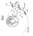
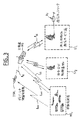
図2は、本発明の静止衛星通信システムの宇宙空間にある部分を示す図である。図3は、地上部分の種々の成分を含むシステム全体を示す図である。
【0030】
空間ダイバーシチの原理を応用した通信システムの主な特性は、一つの発信アンテナおよび複数の受信アンテナを用いることである。発信アンテナと各受信アンテナ間のパスは、「ダイバーシチ・チャネル」として知られている。したがって、ダイバーシチ受信アンテナと同数の「ダイバーシチ・ブランチ(分岐)」が存在する。ダイバーシチの利点を最大限に活用するため、受信アンテナ間の距離は、各ダイバーシチ・ブランチの入口におけるマルチパスが統計的に独立したものとなるように、十分な距離を取る必要がある。
【0031】
図1が示すように、固定障害物または移動障害物が放射電波を複数に反射/拡散および遮蔽することは、ビットエラーレート(BER)の点から、アップリンクの劣化の主な原因である。このことは、従来のアディティブ・ガウス白色雑音(AGWN)伝送リンク(固定サービス)では、見られない。
【0032】
前記のとおり、先行技術のダイバーシチの概念をGEOシステムに応用することは、経済的および(または)技術的な理由から非現実的である。
【0033】
しかしながら、遮蔽エリアの問題が完全に解決できないことを受け入れると、利用可能な「マルチパス」エネルギーをフル活用されたシステムを有することにより、受信衛星に利用できるパワーを最大限に活用することができる。「マルチパス」エネルギーは、二番目に大きいエネルギー成分を構成し、深刻なシャドーエリアの状態に対して、衛星入口でのエネルギーバランスの中で支配的な成分である。
【0034】
本発明は、これらの特性を活用し、前に指摘した欠点を有しない空間ダイバーシチシステムを利用することを可能にする。
【0035】
一つ以上のダイバーシチ衛星受信機(DSR)を主衛星(MS)から短い距離で設置すればよい。本発明における「短」距離とは、地上移動端末と衛星MS間の距離、つまり、約36,000kmの距離に比較して短いということを意味する。以下に示すように、約200〜400kmの衛星間の距離が、本発明の目的を達成するために必要であり、この距離は36,000kmに比べれば短い距離である。この距離は、地上移動端末MTの位置およびその信号のフェージングが起こる環境には関係なく、十分な程度に非相関な「マルチパス」信号を可能にする。したがって、(複数の)DSR衛星およびMS衛星は、「併置されている(colocated)」と考えられる。
【0036】
図2に示される本発明のシステムの実施の形態においては、一つの主衛星MSおよび2個のダイバーシチ衛星受信機DSR1 およびDSR2 が示され、各ダイバーシチ衛星受信機が一つずつ主衛星の両側に位置し、主衛星と同じ静止軌道OG に沿って地球Tの周囲を回っている。主衛星MSは、ダウンリンクld0およびアップリンクlm0を介して端末MTと通信する。好ましい実施の形態において、衛星DSR1 およびDSR2 は受信専用衛星なので、各アップリンクlm1 およびlm2 を介してのみ端末MTと通信する。前記のとおり、衛星DSR1 と衛星MS間の距離および衛星DSR2 と衛星MS間の距離は、一般的に200〜400kmの範囲である。衛星DSR1 および衛星DSR2 は、それぞれ一方向伝送リンクl10およびl20を介して衛星MSと通信する。
【0037】
他の考慮事項(例えば、周波数調整の簡略化等)を無視すれば、衛星が併置されているという事実は、前記の説明の意味において、複数衛星システムの運用に関する要件を非常に簡便にする。すなわち、一つの地上局が3つの衛星を制御でき、その3つの衛星(または、より一般的にはすべての衛星)は、同じ軌道上に併置され、衛星を打ち上げるコストを削減できる等の利点がある。衛星が近接していることの他の利点は、ダイバーシチ衛星受信機DSR1 およびDSR2 は地上制御局に電波を送る必要がないので、衛星間の伝送リンクだけが必要とされることである。これは、パワー必要量を削減できるので、衛星の重量を軽減し、一つの打ち上げロケットでより多くの衛星を運ぶことが可能になり、または、よりパワーの小さい打ち上げロケットで済む。結果的に、衛星間の伝送リンクは、いかなる周波数帯域(例えば、Ka帯域)でも重大な問題が起こることなく動作することができる。主衛星MSとダイバーシチ衛星受信機DSR1 およびDSR2 が極めて接近しているので、干渉やポインティングの問題は起きない。前記のとおり、これらの衛星に必要なパワーは低い。したがって、衛星は小型のもので十分である。
【0038】
アップリンクのみが必要不可欠であることは、本発明の主な特徴の一つであるが、本システムはいくつかまたはすべてのダイバーシチ衛星受信機用のダウンリンクがアップリンクと共存していても運用可能であることは、はっきりと理解されなければならない。アップリンクとダウンリンクの共存は、本システムの宇宙空間にある部分をより柔軟に再構成でき、特に、主衛星MSが故障した場合に役立つ。この場合には、より多くのパワー容量が必要であり、衛星の重量が増加する。それにもかかわらず、衛星が近接していることに由来する利点が損なわれることはない。
【0039】
図3は、地上部分の主な成分を含む本システムの構造全体を示す図である。一般的に、地上部分は以下に示す成分からなる。
【0040】
まず、この地上部分は、地上移動端末MTu から構成される第1のサブシステムからなる。本発明において、「地上」とは、広義の意味である。それは、自動車、船舶や、航空機搭載の端末、人が持ち運ぶ携帯端末を示す。航空機の場合においても、航空機搭載の移動端末と地球表面からの距離が地球と衛星の間の距離より短いので、「地上」と定義する。地上端末は、異なるサイズで、異なるパフォーマンスレベルを供給する。より具体的な例を示すため、すべての端末が、狭帯域(本発明は、広帯域の伝送に等しく十分に応用できるが)内で伝送し、従来のアクセス構成、例えば、FDMA(周波数分割多重接続)またはTDMA/FDMA(TDMA=時分割多重接続)を用いることを仮定することができる。さらに、伝送は、特定のチャネル符号(フォワードエラー訂正:FEC)および特定の変調、例えば、M関連位相シフトキーイング(M−PSK)を用いることを仮定する。発信および受信は、一般的にL帯域またはS帯域で行われる。通常、伝送信号のタイプは、数kbit/s(一般的に、4kbit/s〜10kbit/sの範囲)のビットレートでボイス(音声)およびデータを含む。最後に、「移動端末チャネル」(MTC)は、移動端末MTからユーザのデータを伝送するためのすべてのチャネルを意味する。
【0041】
第2のサブシステムは、地上にある移動体通信サービス局ST1 からなる。これは、主衛星MSと種々の地上通信ネットワークRT 間の直接双方向通信リンクlbiを供給する。ネットワークRT は、個人および(または)公共の電話ネットワークから構成され、通常、地上移動サービス局ST1 は、ユーザ(地上移動端末MTu )のための伝搬ノードおよび国際トラフィック端末局であり、GEO通信衛星を介して接続されている。移動端末チャネル(MTC)は、「リターン」伝送リンクを介して伝送され、主衛星および(または)ダイバーシチ衛星受信機へのアップリンクと直接双方向伝送リンクlbiのダウンリンクから構成される。同様に、地上移動サービス局ST1 からの局チャネルは、「アウト」チャネルを用い、直接双方向伝送リンクlbiおよび(複数の)衛星のダウンリンクから構成される。
【0042】
第3のサブシステムは、種々の地上局ST2 から構成される。地上局ST2 は、種々の衛星制御局(SCS)およびネットワーク制御局(NCS)のための親(マスタ)制御局(MCC)、遠隔測定局等から構成される。これらの局は、当業者に知られており、本発明の範囲外である。したがって、これ以上記載する点はない。「衛星」という言葉は、主衛星MSおよびダイバーシチ衛星受信機、例えば、DSR1 を意味する。
【0043】
一般的に、宇宙空間部分は、以下に記載される成分から構成される。つまり、ここに記載された例では、ダイバーシチ衛星受信機DSR1 が一つしかない。ダイバーシチ衛星受信機DSR1は、一方向衛星間伝送リンクl10を介して衛星MSと通信する。
【0044】
第1のサブシステムは、主衛星MSから構成される。この衛星MSは、「アウト」および「リターン」リンク、すなわち、「アップリンク」および「ダウンリンク」を有し、すべての地上移動端末MTu と通信する。これらのリンクは、アップリンクがlm0、ダウンリンクがld0というそれぞれ単一の数で示され、グループ化されている。もちろん、各端末に別の一対の伝送リンクがある。
【0045】
主衛星MSは、従来のビームシェーピング、ルーティングおよびスイッチング機能を有し、これらの機能は、移動衛星サービス(MSS)のためのGEOタイプの衛星の同様の機能と違いはない。しかしながら、この主衛星は、本発明特有の追加機能も有する。特に、衛星間伝送リンクl10のための、より一般的には、衛星間伝送リンク(上記例では、衛星DSR1 から衛星MSへのリンク)のための専用回路を有することが必要である。この専用回路は、以下において、「衛星間リンク受信装置」と呼ばれる。通常、追加ルーティングおよびマッピング容量を衛星間通信リンクからのダイバーシチチャネルに供給することが必要である。結果的に、本発明の一実施例においては、直接チャネルおよびダイバーシチ衛星受信機(例えば、DSR1 )からのチャネルが、主衛星MS上で結合される。したがって、ダイバーシチ・ブランチを結合することを可能にする専用回路を設ける必要がある。
【0046】
本発明のより重要な側面の一つによれば、第2のサブシステムは、少なくとも一つの併置された空間ダイバーシチ衛星受信機から構成される。記載された例には、衛星DSR1 が一つだけ示されているが、より一般的には、例えば、主衛星の両側に一つずつ衛星受信機が配置される。前記のとおり、衛星受信機DSR1 のような空間ダイバーシチ衛星受信機は、短距離間隔で「併置」された(colocated)衛星である。すなわち、一般的には、衛星MSから200〜400kmの距離で配置される。空間ダイバーシチ衛星受信機は、地上移動端末MTu からのマルチパス信号を受信する空間ダイバーシチ受信を行う。本発明のシステムの管理を簡略化するため、この実施例においては、衛星およびネットワークの制御地上局ST2 は、これらの衛星にもアクセスすることができる。本発明のシステムを簡単に示した本実施例において、空間ダイバーシチ衛星受信機は伝送エネルギーにより主衛星MSと通信する。衛星DSR1 (一般的には、空間ダイバーシチ衛星受信機)は、主衛星MSから遠く離れ、受信されたマルチパス信号の分散成分が2つの衛星(MSおよびDSR1 )の間で相関していないことを保障し、その結果として、以下に示されるように空間ダイバーシチの能力が正しく用いられることとなる。
【0047】
地上部分および宇宙空間部分に加えて、本システムは幾つかの通信リンクを含む。
【0048】
第1のリンクのタイプは、「リターン・リンク」である。「リターン・リンク」には、まず、2つのアップリンクがある。一つは、地上移動端末MTu と主衛星MS間のアップリンクlm0、もう一つは、同じ地上移動端末MTu とあるダイバーシチ衛星受信機DSR1 (一般的には、複数のダイバーシチ衛星受信機)間のアップリンクlm1である。この通信リンクは、本発明において不可欠であり、本発明の目的の達成を可能にするリンクである。
【0049】
第2に、主衛星と移動サービス局ST1 間の双方向伝送リンクlbiのダウンリンクがある。主衛星および移動サービス局は、必ず通信できなければならないことは明らかである。移動サービス局ST1 とダイバーシチ衛星受信機、例えば、DSR1 間のリンクは選択可能であり、本発明のシステムを簡略したシステムには存在しない。
【0050】
この通信リンクは、先行技術のシステムに使用される従来の通信リンクと同じリンクと考えられる。通信は、アディティブ・ガウス白色ノイズ(AGWN)によってのみ影響され、GEO移動衛星サービス(MSS)の場合は、重要であるとは通常考えられていない。
【0051】
第2のリンクのタイプは、「アウト」リンクである。この「アウト」リンクは、まず、移動サービス局ST1 と主衛星MS間の双方向リンクlbiのアップリンクを意味する。アップリンクは、移動体通信サービス局ST1 と衛星DSR1 (または、一般的には、複数の空間ダイバーシチ衛星受信機)間には必要とされない。
【0052】
この通信リンクは、先行技術のシステムにある従来の通信リンクとして考えられる。通信は、アディティブ・ガウス白色ノイズ(AGWN)によってのみ影響され、通常、GEO移動衛星サービス(MSS)の場合、重要であるとは考えられない。
【0053】
次は、移動体通信サービス局ST1 と主衛星MS間の双方向リンクlbiのアップリンクである。このタイプの通信リンクは、衛星DSR1 (または、一般的には、空間ダイバーシチ衛星受信機)と移動体通信サービス局ST1 間にはない。これは、従来の通信リンクであり、移動システムのためのGEO衛星システムに通常求められる要件を満たすものである。
【0054】
最後に、本発明の特徴である第3のリンクのタイプは、衛星間リンク、特に、ダイバーシチ衛星受信機、例えば、DSR1 と主衛星MS間のリンクである。
【0055】
図3において、通信リンクl10は、衛星DSR1 と衛星MS間に設けられる。2つの衛星が地上移動局MTu から受信したそれぞれの信号は、主衛星MS上(実施例1)で、あるいは、主衛星MSがサービス局ST1 に再送した後に、地上(実施例2)で結合される。
【0056】
前記システムの主要構成部分および動作については概略を説明したので、以下に稼働の詳細を示す。より具体的な例として、図3に示した簡略化したシステムについて以下に説明する。一つの併置ダイバーシチ衛星受信機DSR1 が示され、この衛星から地上への通信リンクは示されていない。この特定の構造に本発明の範囲が限定されるものではないことは、明確に理解されなければならない。同様に、本システムの管理と特定の制御および命令システムは、本発明の範囲外であり、当業者によく知られているので、ここでは深く説明しない。
【0057】
本発明によれば、地上移動端末MTu'(携帯端末またはその他の端末)のユーザから見て、1以上のダイバーシチ衛星受信機を使用しているか使用していないかが、すくに分かる。ユーザは、特定の伝送アクセス、変調およびコード構成、例えば、FDMA、TDMAまたはF/TDMA技術を用いる狭帯域構成にしたがって、GEO衛星システムと通信する。これは、必ずそうでなければならないものではなく、本発明はこのような構成に限定されない。
【0058】
複数の反射(図1参照)があるため、地上移動端末MTu が衛星チャネルを介して情報を伝送する際、その情報は、同じ軌道上に併置された衛星MSおよびDSR1 によって、別々のパスを通って受信される。衛星MSおよびDSR1 間の距離は、一般的に200〜400kmであり、関連するシステムの特定のパラメータに影響される。200〜400kmの距離は、衛星MSが受信した信号と衛星DSR1 が受信した信号が統計的に非相関であるために十分な距離なので、空間ダイバーシチの利点を得ることができる。
【0059】
衛星DSR1 上のダイバーシチアンテナは、対応するゲイン/温度(G/T)比で、マルチパス移動端末チャネル(MTC)を受信する。必要なビーム・シェーピングをした後、受信されたマルチパス信号は、無線周波数回路の従来のシステムを通過し、衛星間通信リンクl10の周波数に増幅され、変換される。この信号は、従来の伝送回路(衛星間伝送リンク装置ISLTU。図3には示されていない)を介して、変換された周波数で主衛星MSに伝送される。
【0060】
主衛星MS上のアンテナは、対応するゲイン/温度(G/T)比で、マルチパス移動端末チャネル(MTC)を受信する。衛星MSおよび衛星DSR1 が併置されているので、2つの衛星上の受信アンテナは、(サービスエリアおよび放射パターンの点から)同一である。衛星MSは、衛星間伝送リンクl10を介して、(非相関分岐を構成している)衛星DSR1 が受信したたマルチパス信号の一部を受信する。このダイバーシチ信号は、衛星間リンク受信装置(ISLRU)によって受信される。衛星間リンク受信装置(ISLRU)は、図3に示されていない。この段階で、衛星MSによって受信された直接信号および衛星DSR1 によって受信されたダイバーシチ信号は、一つの信号に結合されなければならない。本発明は、以下の2つの方法で結合を行う。
【0061】
1.地上での信号の結合。
この解決法は、搭載される回路の複雑さの面から、より簡単な解決法である。2つの信号は、「リターン」伝送リンク(双方向伝送リンクlbiのダウンリンク部分)によって、別々に再送され、地上の移動体通信サービス局ST1 で結合される。種々の結合技術が、移動サービス局ST1 で使われる。例えば、最大レート結合(MR−C)、等ゲイン結合(EGC)、または選択結合(SC)が行われる。これらの技術は、W.C. Jackes, John Wiley & Sons: "Microwave Mobile Communication (マイクロ波移動通信)" (1974)に説明されている。この文献は、これらの従来技術の詳細な説明のための引用文献として役に立つものである。本発明は、なんらの特定技術にも限定されないことは、はっきりと理解される必要がある。
【0062】
地上での結合のモードは、伝送リンクlbiが非常に厳しい帯域幅制限にない限り、すべての状態に十分に適合する。それは、帯域幅が「ダイバーシチ・オーダー」に比例する、すなわち、最終的な分析において、ダイバーシチ衛星受信機DSRの数に比例しているからである。逆に言えば、この場合、搭載された信号処理は、従来のGEO衛星の場合に実行される通常の処理、つまり、ビームシェーピング、ルーティング、およびスイッチングに限定される。本発明に必要な追加回路は、上述のISRLU回路およびダイバーシチ信号をリターン・リンク(lbiのダウンリンク部分)にルーティング/マッピングするための追加回路だけである。直接チャネルおよびダイバーシチ移動端末チャネルMTu が結合され、地上でシンクロするので、衛星MSおよび衛星DSR1 の同期が簡単にできる。
【0063】
2.衛星MS上での信号の結合。
この場合、直接マルチパス信号とダイバーシチマルチパス信号が衛星MS上で結合される。以下に示す2つの方法で結合が行われる。
【0064】
a)中間周波数(IF)での結合。
この方法は、各ダイバーシチ・ブランチのために、受信された個々の移動端末チャネルMTu が、逆変換およびビームシェピングの後、時領域または周波数領域で濾過され、他のユーザからの他の信号から分離されることを必要とする。他のユーザからの信号は、IF結合回路を通過する。この回路において、種々のダイバーシチ・ブランチからのすべての信号は、(復調される前に)特定の方法、例えば、選択結合または差動受信結合を用いて結合される。本発明は、いかなる特定の結合技術にも限定されるものではない。結合が完了すると、この方法で結合された信号は、先行技術のGEO衛星の従来のパスに入る。結合された信号は、従来の方法で、衛星MSによって受信された通常の信号と考えることができ、地上(サービス局ST1 )に再送される。
【0065】
この回路は、前記ISLRU回路、移動端末チャネルを濾過し分離する無線周波数ルーティング回路およびIF結合を行う処理装置を含むので、より複雑なものとなる。
この場合、地上への伝送リンクを必要とすることは、先行技術のシステム、つまり、ダイバーシチを有しないシステムが伝送リンクを必要とすることと同様である。結合が衛星MS上で実行されるので、同様のことが地上の設備にも当てはまる。
【0066】
逆に言えば、結合プロセスが同期して実行されなければならないので、主衛星MSおよびダイバーシチ衛星受信機、例えば、DSR1 の同期は、以下の説明のとおり、同期していなければならない。
【0067】
b)基本帯域で結合する。
この方法は、再生機GEO衛星にとって理想的である。この場合、直接または(DSR1 からの)ダイバーシチ移動端末チャネルMTu は、基本帯域で復調され、復調後、復号される前に結合される。この場合、いかなる結合方法も使用できる。
(先行技術のダイバーシチを有しないGEO衛星と比較して)必要とされる追加回路は、以下のとおりである。前記ISLRU回路、ダイバーシチルーティングのための回路、ダイバーシチチャネルおよび結合処理のための追加復調器が必要とされる。
【0068】
双方向伝送リンクlbi、特に、ダウンリンクは、従来のものであり、地上局ST1 の復調器は、なんらの追加回路も必要としない。逆に言えば、主衛星MSおよびダイバーシチ衛星受信機、例えば、DSR1 の同期が必要である。
【0069】
衛星間伝送リンク、例えば、記載された例の伝送リンクl10に関する要件の詳細な説明は以下のとおりである。
【0070】
多くのシミュレーションが実行されてきた。これに基づいて、地上移動端末MTu のユーザによって伝送された信号と、各衛星に対する直接的な見通し線以外の経路で伝送された信号との統計学的特性は、以下の条件を満たす場合、非常に高度に非相関である。
・衛星がおよそ250km〜300kmの間隔で配置されている。
・地上移動端末MTu が放射拡散しやすい市街地環境に位置する。
・伝送がL周波数帯域で行われる。
【0071】
非相関は、都市部においては150km未満の衛星間の距離が必要であり、障害物のない郊外ではもっと大きな距離が必要である。
S周波数帯域またはそれより高い周波数において、リターン・アップリンクは、拡散的な環境にいるユーザの間接リターン・パスが非相関になるため、衛星間の距離を短くても同程度の非相関性が得られる。
【0072】
主衛星MSと補助ダイバーシチ衛星受信機、例えば、衛星DSR1 間の距離が短く、さらに、これらの衛星がGEOタイプの衛星であることによって、特に簡単で低パワーの衛星間リンク、例えば、リンクl10の使用が可能になる。短距離間隔で衛星を併置することは、現代技術を利用するいかなる伝送リンクにとっても、必要とされ、先行技術と同様である。
【0073】
衛星の位置を±0.05゜(南北方向、東西方向にそれぞれ)の範囲内に維持することが、基準となる。これは、衛星間の距離が最短で250km、最長で400kmであることを示す。この場合、よく知られているコンパクトアンテナは、補助衛星(例えば、DSR1 )からの伝送および衛星MS上の受信のために利用できる。相手の衛星の方向に最小25dBiのゲインがあれば、アンテナを電気的または機械的に操作しなくてもよい。20cm×5cmより小さいアンテナ開口部が、約23GHzの衛星通信のために設けられている周波数帯域に適当である。
【0074】
衛星伝送リンク運用の計画は、太陽が1日に必ず、主要ビーム受信アンテナ上で照るが、ただし、気温が華氏170度以下に低下する場所である事実を考慮に入れなければならない。したがって、衛星間リンクの帯域幅の1.4W/MHzより小さい補助衛星(例えば、DSR1 )の無線周波数伝送パワーということになる。雑音および相互変調生成物によって、「リターン」伝送リンクのサービス全部にわずかな劣化が生じる(衛星間リンクの干渉累積レベルは、「リターン」伝送リンク上の信号より下の少なくとも20dBである)。3つ以上の衛星を使用するシステム(このシステムは、本発明のシステムの極端な場合を構成する)の中で最遠のダイバーシチ衛星受信機は、若干大型のアンテナ(これは、周波数調整の点から好ましい選択である)、または高パワーレベルで信号を伝送することを必要とする。これらの方法は、現在の技術の水準からみて、何の問題も起こさない。
【0075】
要するに、軽量(用いられる装置、すなわち、アンテナ等の点から)の衛星間リンクを利用でき、計画された伝送リンク容量を維持する適切な周波数帯域すべてを利用することができる。この容量は、地上移動端末のユーザに割り当てられた周波数スペクトルと、本システムのために設けられた周波数の再利用の程度に依存する。周波数調整は、LEO宇宙船では特に容易である。それは、衛星が本発明のダイバーシチ衛星受信機システムのラインから70゜以上の位置に配置され、はっきりと識別できるからである。データを中継するGEOタイプの衛星は、LEOタイプのユーザと通信するために計算され、通常、周波数調整の問題は起こらない。
【0076】
空間ダイバーシチの概念の利用は、衛星間伝送リンクの存在とは独立したものではあるが、この伝送リンクの利用は特に簡単なものであることは、上記の説明から明らかである。宇宙空間部分が1度より小さい静止軌道上の弧角度でもって「併置」されているが、本発明における幾つかの衛星は、単一の静止衛星と混同されるものではない。それにもかかわらず、周波数割り当てには、なんら重大な問題はない。
【0077】
衛星間伝送リンクの使用により、以下に示す改良が得られる。
1.本システムを実施する者は、一つの衛星のダウンリンクの管理のみを他の管理者との間で調整する必要がある。
2.補助衛星、例えば、DSR1 の主な地上サービスは、「受信専用」タイプであり、その他の目的のために、余った能力又は容量を利用することができる。
3.衛星間伝送リンクの使用は、J. Ventura-Traveset らによる"Normalized Diversity Receiver for Mobile Fading Channel" (Proceedings of the Cost 229 Workshop on Adaptive Systems, Intelligent Approaches, Massively Paralll Computing and Emergent Techniques in Signal Processing and Communications, Bayona(vigo), Spain、1994年10月に所収)に提案されているアーキテクチャに準拠した標準ダイバーシチ受信機(NORD)の設置を可能にする。
【0078】
前記のとおり、多くのシミュレーションが行われ、本発明に基づく仮定の有効性が証明され、先行技術のGEOタイプの移動サービスシステムに比較して、本発明が有効であることが示された。
【0079】
もっとも広く受け入れられた伝送評価システムの一つが利用されている。それは、IEEE Transactions on Vehicles Technology, vol. 34, page 127, August 1985にある、C. Looによる"A statistical mode for a land mobile satellite link" において提案されているものである。これは、一般的な統計システムである。
【0080】
特に、本発明の要件を満たすには以下の3つの条件が考えられる。
1.非常に強く「マスキングされた」チャネル
2.中間の強さで「マスキングされた」チャネル
3.弱く「マスキングされた」チャネル
これらのモデルは、種々のマスキングの状態、種々のエネルギー分配および分散(マルチパス)伝送とサイト伝送の両方を表現する。
【0081】
非直接(マルチパス)信号の伝送パス上でどの程度相関していないのが望ましいかは、W.C. Jackes による上記の "Microwave Mobile COmmunication," John Wiley & Sons, 1974に記載された方法に似た方法により評価される。
【0082】
図1は、任意で複数の拡散と反射が生じる市街地環境を示す図である。前記のとおり、この図は、地上移動局MT1 のアンテナAntによって伝送された信号の種々の分散および拡散源の影響を明確に示す。障害物の数は20で、幾千の環境構成が、モンテ・カルロ法を用いて、統計的に生成された。
【0083】
このようなシミュレーションの結果の一般例は、本明細書の最後の表1に示されている。この結果は、L帯域またはそれより高い周波数を用いて市街地環境では、300kmの衛星間の距離は、ダイバーシチパスが適度に非相関であるのに十分であることを示している。この理論は、よりよい結果はS帯域を用いることによって得られることを予想している。結果的に、そのシミュレーションは、非相関が郊外環境で改良されることを示し、この理論に一致する。
【0084】
市街地環境およびL帯域の選択は、最短の衛星間の距離の計算において十分な余裕を供給する。300km離れた衛星軌道を獲得することは簡単であり、その距離は、もっともよいパフォーマンスを供給する軌道間リンク要件に対応するので、この距離は、本発明のシステムの好ましい実施例に適用される。
【0085】
標準ダイバーシチ受信機(NORD)の概念は、本発明のダイバーシチ通信システムのすべてのパフォーマンス評価するために使われてきた。この概念のより詳細な記載については、前記のJ.Ventura-Travesetらの論文を参照されたい。
【0086】
さらに、前記のとおり、本発明は、使われている受信機のタイプを用いない。種々の受信機、すなわち、可干渉性受信機、差動受信機およびパイロット周波数受信機の構造で試験が行われてきた。
【0087】
種々の通信技術が使われている。つまり、本発明は、4元位相シフトキーイング(QPSK)および2/3TCM 8−PSK(位相シフトキーイングタイプの8つのUnderboeck符号を有するトレリス符号変調)の試験を行う。これらの伝送技術は、2つの異なる伝送戦略をカバーし、GEOタイプの衛星に基づく移動伝送サービスのために提案されているので、これらの伝送技術が選択される。これは、M.J. Miller らの "Satellite communications: mobile and fixed services," Kluwer Academic Publishers (1993) に記載されている。
【0088】
結果的に、多くの仮定がなされているが、本発明、すなわち、移動通信サービスにおける伝送状態のより通常の状況をカバーするような仮定を用いている。この中で、10-2から10-5のビットエラーレートが考えられ、このタイプの応用の通常の要件のほとんどをカバーする。
【0089】
本システムの比較試験が、先行技術の従来のあるGEO衛星通信システムと、空間ダイバーシチと一つの「併置」補助衛星を利用した本システムを用いて、これらの幾つかの仮定に関して行われた。
【0090】
より具体的な例を示すために、本明細書の最後の表II〜IVが本発明のシステムによって得られる、従来のシステムに対するパフォーマンスの改良を示す。より正確には、表II〜IVは、前記の3つのモデルをカバーする。3つのモデルとは、非常に強く「マスキングされた」チャネル、中間の強さで「マスキングされた」チャネル、および弱く「マスキングされた」チャネルである。前記のNORDの概念は、可干渉性検知受信機と共に使われる。直接およびダイバーシチ信号は、「最大レート(maximal rate)」技術を用いて結合された。各表において、第1のコラムは、ビットエラーレート(BER)であり、第2のコラムは、非符号QPSK伝送技術(non-coded QPSK transmission technique) であり、第3のコラムは、2/3TCM 8−PSK伝送技術である。
【0091】
第2および第3のコラムにおいて、各BERの値に対して、本発明のシステムが同じ条件で、ただし、ダイバーシチ衛星なしで動作する従来のシステムで提供されたパフォーマンスの改良は、デシベルで示される。
【0092】
3つの環境において、特に、障害物の多い市街地環境では、本発明のシステムは、より高いパフォーマンスの改良が得られる。もし、低ビットエラーレートが必要なら、市街地環境では改良は20dB以上で、他の2つの場合は少なくとも16dBである。これらの値は、非符号化QPSK伝送技術に対応する。さほど大きくはないが、ある程度の改良は、2/3TCM 8−PSK伝送技術についても見られる。
【0093】
対応する結果は特定の表に示されていないが、比較できる結果は、差検知受信機および差結合で得られ、一方、パイロット周波数受信機および擬最大結合(quasi-maximal combination) でも得られる。
【0094】
すべての場合において、特に、伝送技術または受信機のタイプにもかかわらず、本発明のシステムは、従来のGEO衛星通信システムに比較してパフォーマンスの改良が得られる。
【0095】
前記のとおり、本発明のシステムは、複数のダイバーシチ衛星受信機を含み、パフォーマンスを向上している。本明細書の最後の表Vは、従来のシステムと本発明のシステムの比較を示し、一つのダイバーシチ衛星受信機(コラム2)または2つのダイバーシチ衛星受信機(コラム3)から構成され、ビットエラーレートは、10-2〜10-5の間で変化する。環境は市街地であり、伝送技術は非符号QPSKであり、受信機は可干渉性検知タイプであり、結合は最大レート・タイプである。この条件で、表IIの第2のコラムに示される値が得られ、第2のダイバーシチ衛星受信機によって得られるパフォーマンスの向上を示す(図2におけるDSR2 )。改良は、10-2のビットエラーレートに対して1.4dBから、10-5のビットエラーレートに対して約5dB、10-3の平均ビットエラーレートに対して約3dBである。第2の衛星によって得られる改良は、いくつかの応用例において有意である。
【0096】
すべての衛星通信システムにおいて考えられる他の重要なパラメータは、その容量、すなわち、具体的に言えば、同時に処理できるユーザの最大数である。移動衛星サービスを提供する衛星が利用できる周波数スペクトルは、非常に不足しているリソースである。したがって、高周波数再利用(FR)要素を利用できることが必要である。信号チャネルの必要な帯域幅および隣接したチャネル間の分離を最小にすることが必要である。多くの研究が引き続いて行われ、いくつかの解決法が先行技術のシステムで実行されてきた。すなわち、解決法とは、適当な変調フォーマット(例えば、π/4 QPSK)、バトラーマトリクスを使ったビーム形成ネットワーク(DBFN)等である。
【0097】
採用された解決法にもかかわらず、フェージングに対するチャネルサブジェクトの容量は、チャネル干渉値に非常に依存する。本発明のシステムは、空間ダイバーシチを用い、このエリアでも従来のGEOシステムの範囲で基本の改良を示す。
【0098】
例えば、表VIは、パフォーマンスの改良を強調する。その改良とは、本発明のシステムが一つのダイバーシチ衛星受信機を用い、その衛星受信機は、同じチャネル(共通チャネル干渉)における搬送波干渉によって影響される従来のGEO衛星システムと比較され、ビットエラーレートは10-2〜10-5の値を示す。この表は、4つのコラムからなり、コラム2および3は、それぞれ、25dB、30dB、40dBの信号干渉レート(SIR)を示す。
【0099】
前述のNORDの概念が使われ、受信機の構造は、可干渉性検知タイプであり、直接信号とダイバーシチ信号は「最大レート」技術を用いて結合され、伝送技術は、非符号QPSKであった。考えられる環境は、市街地タイプ、すなわち、高度に「マスキングされた」タイプである。
【0100】
パフォーマンスの改良は、すべての場合で示された。「∞」とは、従来のGEOシステムを用いた場合、第1のコラムに示されたビットエラーレート(BER)が達成できないことを示す。これは、本発明のシステムが達成できるビットエラーレートの最小値を低下させることを意味する。
さらに、伝送リンク上の搬送波/雑音比(C/N)は、非常に改良された。
【0101】
したがって、システムの容量を増加させることが可能である。例えば、本発明の場合、わずか25dBのSIR値で、パフォーマンスは、従来のGEOシステムの場合の40dBと同じく高いSIR値の範囲で改良される。言い換えれば、本発明のシステムでSIRを25dBに軽減し、一方、搬送波/雑音比(C/N)の点から改良されたパフォーマンスを獲得することができる。したがって、そのシステムの容量は増加され、または、ビームの数は、実質的に軽減される(前記FR要素において増加する)。
【0102】
単純化のための仮定がいくつか前記記載において採用されている。特に、インターリービングは理想的であるとしたが、実際の使用状況下の場合ではそのようなことはない。インターリービングの深さは、必然的に有限となる。この主な理由は、インターリービングと非インターリービングが時間の遅延を伝送に引き起こし、望ましくないことである。また、本発明のシステムは、同様の使用条件下で、従来のシステムと比較して改良に貢献し、この種の問題の重要性は低い。
【0103】
本発明のシステムの動作を示すために、レイリーチャネル(Rayleigh channel)の場合、試験が行われてきたが、同様の結果が、移動サービスチャネルに関する異なる状況で得られる。使われた伝送技術は、前記の2/3TCM 8−PSKタイプである。そのシステムは、一つの「併置」ダイバーシチ受信機を含むものであった。
【0104】
表VII は同様な結果を示し、その結果は、2つのビットエラーレート値(10-2および10-3)と4つのインターリービング値、すなわち、I=0、I=10,I=20、I=30である。
【0105】
本発明のシステムのパフォーマンスは、すべての場合において、従来のシステムのパフォーマンスより優れている。さらに、インターリービングが深くなればなるほど、パフォーマンスは向上する。言い換えれば、有限のインターリービングの深さの効果は、従来のGEOシステムほど本発明のシステムに影響を与えない。
【0106】
前記記載から、本発明が先に記載された目的を達成することは明らかである。
本発明のシステムは、従来技術GEOタイプの衛星システムに比べて、より多くの利点を有する。以下に、利点を簡単に示す。
1.信号のフェージングが激しい状態で、搬送波/雑音比(C/N)の点から、「リターン」伝送リンクを改良する。搬送波/雑音比の軽減は、以下の目的またはいくつかの目的の組み合わせで使われる。
・搭載されたアンテナのサイズが小さくできる。
・システムおよび信号のフェージングのマージンの利用が増加できる。
・地上移動端末の実効等方向放射力(EIRP)が軽減できる。
・システムのパフォーマンスを劣化させずに、簡単な符号構成を使うことができる。したがって、余剰が削減され(システムの容量が相関的に増加され)、必要なインターリービングの深さが軽減される(したがって、時間遅延が短くなる)。
【0107】
2.システムの干渉(例えば、共通チャネルの干渉および隣接チャネルの干渉)を考慮する場合、搬送波/雑音比(C/N)を削減する改良ができる。前記搬送波/雑音比(C/N)の削減は、以下の目的のうち一つまたはいくつかの組み合わせを達成するために使われる。
・本システムの周波数の再利用要素FRを増加させる。すなわち、GEO衛星システムの容量を増加させ、衛星のリターン・コストを増加させる。
・衛星の「ハードウェア」部分(回路等)を簡略化することによって、システムの容量を削減することなく、ビームの数を削減する。したがって、コストが削減される。
【0108】
3.あらゆる特定の符号およびチャネル状態において、本発明のシステムは、必要なインターリービングの深さを軽減でき、したがって、伝送時間を相関的に削減できる。
【0109】
4.移動サービスシステムは、より少ない好ましいチャネルの状態でもっとも効果的であるので、パフォーマンスをより均一にする。
【0110】
本発明は、記載された実施例、特に、図2および図3に関する記載に限定されない。特に、前記のとおり、本発明は、使用される受信機のタイプ、符号構成および(または)伝送技術について、限定されるものでは全くない。「併置された(colocated) 」補助衛星の数は理論上は無限であるが、実用およびコストを考慮した結果、数が限定される。簡略化された実施例(図3)においては、一つのダイバーシチ衛星受信機(DSR1 )が使われている。好ましい実施例において、2つの衛星(DSR1 およびDSR2 )が使われ、この衛星は、同じ静止軌道OG上で一つずつ衛星MSの両側に配置されている(図2)。前記のとおり、ダイバーシチ衛星受信機、例えば、衛星DSR1 は、地上移動端末MTu から衛星DSR1 へのアップリンクのみを必要とし、主衛星MSに対する一方向衛星間リンクが供給される。これは、本発明の範囲内である。
【0111】
【表1】

【表2】
【表3】
【表4】
【表5】
【表6】
【表7】
【図面の簡単な説明】
【図1】地上移動端末と通信衛星との間の通信における陰影領域(シャドーエリア)と多重反射の現象を示す。
【図2】本発明の静止衛星通信システムの「宇宙空間部分」の構成を示す外観図である。
【図3】本発明の静止衛星通信システムの相対的な構成を示し、このシステムの「地上部分」の種々の要素が含まれる。[0001]
BACKGROUND OF THE INVENTION
The present invention relates to a system for transmitting a radio signal via a geostationary communication satellite. The present invention particularly relates to a terrestrial mobile terminal, and more particularly to a portable mobile terminal.
[0002]
[Prior art]
During the last decade, considerable research and development efforts have been made by the industry to provide mobile satellite services (MSS). “Key Payload Technologies for Future Satellite Personal Communications: A European Perspective” by J. Ventura-Traveset et al. (International Journal) of Satellite Communications, Vol. 13, pages 117-135, March-April 1995), even at the beginning of a new century, cellular communications networks on Earth cannot cover more than 15% of the Earth's surface. It will be described. Therefore, mobile satellite services continue to attract attention.
[0003]
These services can be categorized according to the type of satellite used, in particular according to the orbital height of the satellite arrangement or the reach of the ground service.
[0004]
The former classification can usually distinguish between low earth orbit (LEO), middle earth orbit (MEO), geosynchronous orbit (GEO), and highly elliptical orbit (HEO).
[0005]
The latter classification usually results in a classification between a regional coverage system and a global coverage system.
[0006]
In outer space, the present invention uses a geostationary satellite, referred to below as a “GEO” satellite for simplicity. It is equally applicable to systems that cover a certain region and systems that cover the whole world.
[0007]
The terrestrial portion of the system includes a mobile terminal (MT). These have various aspects. They are land vehicles, marine ships, aircraft, etc., including on-board terminals or mobile plant equipment. Handheld mobile terminals are also included in this system. These terminals are hereinafter referred to as “MT”.
[0008]
The space and ground portions of the system of the present invention are described in detail below.
When geostationary satellites can be used, communication systems have obvious advantages, they are
・ Since there is experience in reliability in orbit suitable for use, low risk in terms of science and technology,
・ The legal and administrative aspects can be simplified,
・ There is a possibility of regional coverage by a few spaceships,
・ The ability to simplify network control,
The Doppler problem is small and the spacecraft tracking subsystem is simple,
-A small number of geostationary satellites is sufficient to cover the global area, and usually a single location is sufficient for regional coverage, for example in Europe. It is.
[0009]
[Problems to be solved by the invention]
However, this type of system is not completely free from problems or limitations and includes the following problems.
-Equivalent isotropic radiated power (EIRP) or gain / temperature (GT) of the mobile terminal (MT) when it is in a particularly unfavorable situation, for example, in an extremely shaded area ) The parameter value is very high or excessive. The only alternative is to accept the reduced availability of services instead of keeping the above parameters within acceptable limits.
• Requires a very large satellite antenna or a high power satellite.
Longer call delay time becomes a bigger problem, as it requires complex code to be used and a long delay time to be inserted and removed to destroy inherent channel memory effects .
• Satellite launches become very expensive for systems with low-capacity mobile satellite services.
[0010]
Due to the four limitations mentioned above, there is some research for an alternative solution to conventional methods that use satellites in lower orbits (MEO or LEO) for the application purposes covered by the present invention. It was pushed forward by. These alternatives to the prior art have more technical problems compared to the above methods using geostationary satellites, but are more suitable for the target application purpose.
[0011]
One object of the present invention is to alleviate the limitations of conventional communication systems using geostationary satellites while retaining the advantages of such systems. One particular object of the present invention is to improve uplink operation. That is, the operation of the link from the mobile terminal (MT) on the earth to the communication satellite is improved.
[0012]
[Means for Solving the Problems]
For the above purpose, the present invention uses space diversity technology. Use at least one auxiliary satellite in geostationary orbit associated with the primary satellite. They are placed on a common stationary orbit at a distance that is relatively small compared to the magnitude of these trajectories. Although communication over a microwave link is preferred, the present invention is not limited to this. The main satellite provides two-way communication for the ground mobile terminal MT. Auxiliary satellites simply provide a directional uplink. That is, the function of the auxiliary satellite is limited to receiving a call from the ground mobile terminal MT. Auxiliary satellites can be small because the required power is considerably lower than that required for a primary satellite that must cover communication to a large portion of the earth's surface. The additional launch costs for the auxiliary satellites are low compared to the main cost and the control procedure is easy to implement.
[0013]
The principle of spatial diversity is well known per se. It has been applied to satellite systems that use lower orbits (LEO or MEO).
The mobile satellite service channel is substantially different from the additive white gaussian noise (AWGN) channel of the conventional fixed satellite service. This is because there is a shadow area (shadow area) caused by an obstacle obstructing transmission, and there is multiple reflection at a location adjacent to the mobile terminal MT. Diversity techniques are used to eliminate these two undesirable effects.
[0014]
The term “diversity” used in the field of prior art communication systems lacks unity and covers a very different concept as a practical problem: frequency diversity, time diversity, path diversity, elevation angle diversity. Polar diversity, orbital diversity, etc. The method of installing a diversity receiver is very diverse, ranging from the simplest to the most complex.
[0015]
Conventional diversity systems use a plurality of identical satellites in different orbits as non-stationary (LEO, MEO, or intermediate circular orbit (ICO) satellite) satellites. ICO type systems include the GLOBALSTAR and INMARSAT P-21 commercial satellite systems.
[0016]
The operation of this type of system is based on certain statistical assumptions. That is, one of the satellites in the satellite group arrangement is on the line of sight (LOS) of the ground mobile terminal MT. This direct path (or “physical” communication channel) is necessarily the optimal path and is preferred over the concept of “energy multipath” to improve the quality of communication.
[0017]
This concept can be considered to be applied to the GEO system as it is. However, such direct replacement does not solve the problems specific to this type of communication system, and direct replacement may be difficult if not impossible to implement.
[0018]
It is always necessary for at least one satellite that the line-of-sight LOS to the ground mobile terminal MT necessary for communication is not disturbed. Therefore, a group of satellites with different elevation angles and an uncorrelated line of sight LOS is needed.
[0019]
The extension of this concept to the GEO system is not straightforward and even unrealistic from an economic and / or technical point of view. The distance between GEO satellites must be very large, intersatellite links between satellites (ISL) become very complex, and also requires a very large power and therefore a large size satellite And Considering the increased delay time based on the distance between satellites, doubts may arise regarding the operation of such a system. Finally, it is at least not guaranteed in all cases that the call is not disturbed.
[0020]
Therefore, a system according to the invention is a system for the transmission of radio signals between at least one ground station and at least one ground mobile terminal via geostationary communication satellites in a specific orbit around the earth, A bi-directional transmission link between a satellite and an individual terrestrial mobile terminal, a bi-directional transmission link between the satellite and an individual ground station, an individual auxiliary satellite in the specific orbit and sharing an orbit. A spatial diversity communication system comprising: a transmission link between the terrestrial mobile terminal and a satellite-to-satellite transmission link between each auxiliary satellite sharing a common orbit and a geostationary communication satellite or main satellite. Form.
[0021]
DETAILED DESCRIPTION OF THE INVENTION
The invention will be better understood and the features and advantages of the invention will become apparent upon reading the following detailed description with reference to the accompanying drawings, in which:
[0022]
One of the main objectives of the present application is to improve the performance of a conventional GEO type system, in particular to solve the problem of shadowed areas. Therefore, it is necessary to briefly explain this shadow phenomenon.
[0023]
FIG. 1 shows a ground mobile terminal MT 1 FIG. 2 is a diagram illustrating a main phenomenon that occurs in communication between geostationary satellites (not shown in FIG. 1).
[0024]
As shown below, the present invention relates to a transmission link called “uplink” described in the introductory part (preamble) of the present description, and this type of transmission link is shown in FIG.
[0025]
Ground mobile terminal is car V 1 Assume that the car is located in an urban environment. In general, this type of environment, i.e. an urban area, has many obstacles (building O in FIG. 1). b1 , O b2 . . . O bx , Tree O by , Other vehicles V that are moving or stopped 2 Etc.) causes many problems. Car V 1 Whenever the mobile terminal moves, these various obstacles 1 Shields all or part of the radio wave radiation transmitted by or causes multiple reflections.
[0026]
In order to explain the above phenomenon, FIG. 1 Antenna A nt Five radiated radio waves b transmitted from 1 ~ B Five Is shown. First radio wave b 1 Is a high-rise building Ob 1 Is completely shielded by. Second radio wave b 2 Is a high-rise building Ob 1 Reflected by the top edge of. Reflected radio wave b ' 2 Is within the range of the receivable angle of the transmission link l c (the shaded area in FIG. 1), the reflected radio wave b ′ 2 Is transmitted to a communication satellite (not shown in FIG. 1). Third radio wave b Three Is a tree or obstacle O by Reflected and / or diffused by. This radio wave is an obstacle O by Reflected and / or diffused by the radio wave b ′ Three Occurs. Radio wave b Four Is a moving obstacle, ie car V 2 ' Reflected by the radio wave b ′ Four Occurs. Radio wave b ' Five Is a number of buildings, ie obstacles O b2 And O b3 Therefore, the reflected radio wave b ′ is reflected in plural. Five And b " Five Occurs.
[0027]
In the above simple example, the radiant energy (transmission link 1c) emitted toward the satellite changes over a wide range at random, and this change is caused by the environment that is out of control and the terminal MT. 1 Car V 1 Affected by the movement of the. The intensity of the radio wave that finally reaches the satellite also changes randomly, and this intensity is the same as the obstacle and the terminal MT. 1 It depends on the distance between.
[0028]
One embodiment of the GEO-type satellite communication system of the present invention is described in FIGS.
[0029]
FIG. 2 is a diagram showing a part in the outer space of the geostationary satellite communication system of the present invention. FIG. 3 is a diagram showing the entire system including various components of the ground portion.
[0030]
The main characteristic of a communication system that applies the principle of space diversity is that it uses one transmitting antenna and a plurality of receiving antennas. The path between the transmitting antenna and each receiving antenna is known as a “diversity channel”. Therefore, there are as many “diversity branches” as there are diversity reception antennas. In order to take full advantage of diversity, the distance between receive antennas should be sufficient so that the multipaths at the entrance of each diversity branch are statistically independent.
[0031]
As FIG. 1 shows, the fact that a fixed obstacle or a moving obstacle reflects / spreads and shields a plurality of radiated radio waves is a major cause of uplink degradation in terms of bit error rate (BER). This is not seen with conventional additive Gaussian white noise (AGWN) transmission links (fixed services).
[0032]
As noted above, applying the prior art diversity concept to GEO systems is impractical for economic and / or technical reasons.
[0033]
However, accepting that the problem of shielded areas cannot be fully solved, having a system that takes full advantage of the available “multipath” energy can maximize the power available to the receiving satellite. . “Multipath” energy constitutes the second largest energy component and is the dominant component in the energy balance at the satellite entrance to the severe shadow area conditions.
[0034]
The present invention takes advantage of these properties and makes it possible to utilize a spatial diversity system that does not have the disadvantages pointed out previously.
[0035]
One or more diversity satellite receivers (DSRs) may be installed at a short distance from the main satellite (MS). The “short” distance in the present invention means that the distance between the terrestrial mobile terminal and the satellite MS is short compared to the distance of about 36,000 km. As will be shown below, a distance between satellites of approximately 200-400 km is required to achieve the objectives of the present invention, which is a short distance compared to 36,000 km. This distance allows for a sufficiently multi-correlated “multipath” signal regardless of the location of the ground mobile terminal MT and the environment in which the signal fading occurs. Thus, the DSR satellite (s) and the MS satellite (s) are considered “colocated”.
[0036]
In the embodiment of the system of the invention shown in FIG. 2, there is one primary satellite MS and two diversity satellite receivers DSR. 1 And DSR 2 Each diversity satellite receiver is located on both sides of the main satellite and has the same geostationary orbit O as the main satellite. G Around the Earth T. Main satellite MS is downlink d0 And uplink l m0 Communicates with the terminal MT via. In a preferred embodiment, the satellite DSR 1 And DSR 2 Is a receive-only satellite, so each uplink lm 1 And lm 2 Communicates with the terminal MT only via As mentioned above, satellite DSR 1 Between satellite and satellite MS and satellite DSR 2 The distance between the satellite MS and the satellite MS is generally in the range of 200 to 400 km. Satellite DSR 1 And satellite DSR 2 Are each one-way transmission links Ten And l 20 Communicate with the satellite MS via
[0037]
The fact that satellites are juxtaposed if other considerations (eg simplification of frequency adjustment, etc.) are ignored makes the requirements for operating a multi-satellite system very simple in the sense of the above description. That is, one ground station can control three satellites, and the three satellites (or more generally all satellites) are juxtaposed on the same orbit, and the cost of launching the satellites can be reduced. is there. Another advantage of satellite proximity is the diversity satellite receiver DSR. 1 And DSR 2 Since there is no need to send radio waves to the ground control station, only a transmission link between satellites is required. This can reduce power requirements, thus reducing the weight of the satellite and allowing more satellites to be carried with a single launch rocket, or with a lower power launch rocket. As a result, the transmission link between satellites can operate without significant problems in any frequency band (eg, Ka band). Main satellite MS and diversity satellite receiver DSR 1 And DSR 2 Are so close that there will be no interference or pointing problems. As mentioned above, the power required for these satellites is low. Therefore, a small satellite is sufficient.
[0038]
The fact that only the uplink is indispensable is one of the main features of the present invention, but the system operates even if the downlink for some or all diversity satellite receivers coexists with the uplink. It must be clearly understood that it is possible. The coexistence of the uplink and the downlink can reconfigure a part of the system in outer space more flexibly, and is particularly useful when the primary satellite MS fails. In this case, more power capacity is required and the weight of the satellite increases. Nevertheless, the benefits derived from the close proximity of the satellites are not compromised.
[0039]
FIG. 3 shows the overall structure of the system including the main components of the ground part. Generally, the above-ground part consists of the following components.
[0040]
First, this ground part is the ground mobile terminal MT. u It consists of the 1st subsystem comprised from these. In the present invention, “terrestrial” has a broad meaning. It refers to automobiles, ships, airplane-equipped terminals, and portable terminals carried by people. Even in the case of an aircraft, since the distance from the mobile terminal mounted on the aircraft and the surface of the earth is shorter than the distance between the earth and the satellite, it is defined as “ground”. Ground terminals provide different performance levels at different sizes. To illustrate a more specific example, all terminals transmit within a narrow band (although the present invention is equally well applicable to wideband transmissions) and use conventional access configurations such as FDMA (frequency division multiple access). ) Or TDMA / FDMA (TDMA = time division multiple access) can be assumed. Further, assume that the transmission uses a specific channel code (Forward Error Correction: FEC) and a specific modulation, eg, M-related phase shift keying (M-PSK). Transmission and reception are generally performed in the L band or the S band. Usually, the type of transmission signal includes voice and data at a bit rate of several kbit / s (generally in the range of 4 kbit / s to 10 kbit / s). Finally, “mobile terminal channel” (MTC) means all channels for transmitting user data from the mobile terminal MT.
[0041]
The second subsystem is a mobile communication service station ST located on the ground. 1 Consists of. This is because the main satellite MS and various terrestrial communication networks R T Direct two-way communication link between bi Supply. Network R T Consists of a personal and / or public telephone network and is usually a ground mobile service station ST 1 The user (ground mobile terminal MT u ) And an international traffic terminal station, which are connected via a GEO communication satellite. The mobile terminal channel (MTC) is transmitted over a “return” transmission link and is an uplink and direct bi-directional transmission link to the primary satellite and / or diversity satellite receiver. bi It consists of the downlink. Similarly, ground mobile service station ST 1 The station channel from the “out” channel uses a direct bi-directional transmission link bi And the satellite downlink (s).
[0042]
The third subsystem consists of various ground stations ST 2 Consists of Ground station ST 2 Consists of a master control station (MCC), a telemetry station, etc. for various satellite control stations (SCS) and network control stations (NCS). These stations are known to those skilled in the art and are outside the scope of the present invention. Therefore, there is no point to describe any more. The term “satellite” refers to the main satellite MS and the diversity satellite receiver, eg DSR 1 Means.
[0043]
In general, the outer space portion is composed of the components described below. That is, in the example described here, the diversity satellite receiver DSR 1 There is only one. The diversity satellite receiver DSR1 is a unidirectional inter-satellite transmission link l. Ten Communicate with the satellite MS via
[0044]
The first subsystem is composed of the main satellite MS. This satellite MS has “out” and “return” links, ie “uplink” and “downlink”, and all terrestrial mobile terminals MT u Communicate with. These links are uplinks m0 , Downlink is l d0 Each is represented by a single number and is grouped. Of course, each terminal has another pair of transmission links.
[0045]
The main satellite MS has conventional beam shaping, routing and switching functions, which are no different from similar functions of GEO-type satellites for mobile satellite services (MSS). However, this main satellite also has additional functions specific to the present invention. In particular, intersatellite transmission links Ten And more generally for intersatellite transmission links (in the above example, satellite DSR 1 It is necessary to have a dedicated circuit for the link to the satellite MS. This dedicated circuit is hereinafter referred to as “inter-satellite link receiver”. Typically, it is necessary to provide additional routing and mapping capacity to the diversity channel from the intersatellite communication link. Consequently, in one embodiment of the present invention, direct channel and diversity satellite receivers (eg, DSR) 1 ) From the main satellite MS. Therefore, it is necessary to provide a dedicated circuit that makes it possible to combine the diversity branches.
[0046]
According to one of the more important aspects of the present invention, the second subsystem comprises at least one juxtaposed spatial diversity satellite receiver. The example described includes the satellite DSR 1 However, more generally, for example, one satellite receiver is arranged on each side of the main satellite. As mentioned above, satellite receiver DSR 1 Spatial diversity satellite receivers such as are satellites that are “colocated” at short-range intervals. That is, it is generally arranged at a distance of 200 to 400 km from the satellite MS. The space diversity satellite receiver is connected to the ground mobile terminal MT. u Space diversity reception for receiving a multipath signal from is performed. In order to simplify the management of the system of the present invention, in this embodiment the satellite and network control ground station ST 2 Can also access these satellites. In this embodiment, which is a simplified illustration of the system of the present invention, the spatial diversity satellite receiver communicates with the main satellite MS by transmission energy. Satellite DSR 1 (In general, a spatial diversity satellite receiver) is far away from the main satellite MS, and the received multipath signal has two distributed components (MS and DSR). 1 ), And as a result, the ability of spatial diversity is used correctly as shown below.
[0047]
In addition to the ground and outer space parts, the system includes several communication links.
[0048]
The type of the first link is “return link”. The “return link” has two uplinks. One is the ground mobile terminal MT u Uplink between satellite and main satellite MS m0 The other is the same ground mobile terminal MT u A certain diversity satellite receiver DSR 1 Uplink between (typically multiple diversity satellite receivers) m1 It is. This communication link is indispensable in the present invention and is a link that enables the object of the present invention to be achieved.
[0049]
Second, the main satellite and mobile service station ST 1 Bidirectional transmission link between bi There is a downlink. Obviously, the primary satellite and the mobile service station must be able to communicate. Mobile Service Station ST 1 And diversity satellite receiver, eg DSR 1 The link between is selectable and does not exist in a simplified system of the present invention.
[0050]
This communication link is considered the same link as the conventional communication link used in prior art systems. Communication is only affected by additive Gaussian white noise (AGWN), and in the case of GEO Mobile Satellite Service (MSS), it is usually not considered important.
[0051]
The second link type is an “out” link. This “out” link is first established by the mobile service station ST 1 Link between satellite and main satellite MS bi Means uplink. Uplink is mobile communication service station ST 1 And satellite DSR 1 It is not required between (or generally multiple spatial diversity satellite receivers).
[0052]
This communication link can be considered as a conventional communication link in prior art systems. Communication is only affected by additive Gaussian white noise (AGWN) and is generally not considered important for GEO Mobile Satellite Service (MSS).
[0053]
Next, mobile communication service station ST 1 Link between satellite and main satellite MS bi Is the uplink. This type of communication link is a satellite DSR 1 (Or, generally, a space diversity satellite receiver) and a mobile communication service station ST 1 Not in between. This is a conventional communication link that meets the requirements normally required of a GEO satellite system for mobile systems.
[0054]
Finally, the third link type that is characteristic of the present invention is the inter-satellite link, in particular a diversity satellite receiver, eg DSR. 1 And the main satellite MS.
[0055]
In FIG. 3, the communication link l Ten The satellite DSR 1 And satellite MS. Two satellites are terrestrial mobile stations MT u Are received on the main satellite MS (Example 1), or the main satellite MS receives the service station ST. 1 After being retransmitted, they are combined on the ground (Example 2).
[0056]
Since the main components and operation of the system have been outlined, the operation details will be described below. As a more specific example, the simplified system shown in FIG. 3 will be described below. One side-by-side diversity satellite receiver DSR 1 And the communication link from this satellite to the ground is not shown. It should be clearly understood that the scope of the present invention is not limited to this particular structure. Similarly, the management of this system and the specific control and command system are outside the scope of the present invention and are well known to those skilled in the art and will not be described in depth here.
[0057]
According to the invention, the ground mobile terminal MT u ' From the user of the (mobile terminal or other terminal), it can be easily seen whether one or more diversity satellite receivers are used. The user communicates with the GEO satellite system according to a specific transmission access, modulation and code configuration, eg, a narrowband configuration using FDMA, TDMA or F / TDMA technology. This is not necessarily the case, and the present invention is not limited to such a configuration.
[0058]
Ground mobile terminal MT due to multiple reflections (see FIG. 1) u When transmitting information over a satellite channel, the information is received from satellites MS and DSR collocated in the same orbit. 1 Are received via separate paths. Satellite MS and DSR 1 The distance between is typically 200-400 km and is affected by the specific parameters of the relevant system. The distance from 200 to 400 km is the distance between the signal received by satellite MS and satellite DSR. 1 Since the received signal is statistically uncorrelated, the distance is sufficient so that the advantage of spatial diversity can be obtained.
[0059]
Satellite DSR 1 The upper diversity antenna receives a multipath mobile terminal channel (MTC) with a corresponding gain / temperature (G / T) ratio. After performing the necessary beam shaping, the received multipath signal passes through a conventional system of radio frequency circuits and is inter-satellite communication link l. Ten Are amplified and converted. This signal is transmitted to the main satellite MS at a converted frequency via a conventional transmission circuit (inter-satellite transmission link device ISLTU, not shown in FIG. 3).
[0060]
An antenna on the main satellite MS receives a multipath mobile terminal channel (MTC) with a corresponding gain / temperature (G / T) ratio. Satellite MS and satellite DSR 1 Are juxtaposed, the receive antennas on the two satellites are identical (in terms of service area and radiation pattern). Satellite MS is an inter-satellite transmission link Ten Via satellite DSR (which constitutes an uncorrelated branch) 1 A part of the received multipath signal is received. This diversity signal is received by an inter-satellite link receiver (ISLRU). The intersatellite link receiver (ISLRU) is not shown in FIG. At this stage, the direct signal received by the satellite MS and the satellite DSR 1 Diversity signals received by must be combined into one signal. In the present invention, bonding is performed by the following two methods.
[0061]
1. Signal combination on the ground.
This solution is a simpler solution in terms of the complexity of the mounted circuit. The two signals are “return” transmission links (bidirectional transmission links l). bi Of the mobile communication service station ST on the ground. 1 Combined with Various combining techniques are available for the mobile service station ST. 1 Used in For example, maximum rate combining (MR-C), equal gain combining (EGC), or selective combining (SC) is performed. These techniques are described in WC Jackes, John Wiley & Sons: "Microwave Mobile Communication" (1974). This document serves as a citation for a detailed description of these prior art. It should be clearly understood that the present invention is not limited to any particular technique.
[0062]
The mode of coupling on the ground is the transmission link bi Is well suited to all conditions, unless it is under very tight bandwidth limitations. This is because the bandwidth is proportional to the “diversity order”, ie, in the final analysis, proportional to the number of diversity satellite receivers DSR. Conversely, in this case, the on-board signal processing is limited to the normal processing performed in the case of a conventional GEO satellite, namely beam shaping, routing, and switching. The additional circuitry required for the present invention includes the ISRLU circuit and diversity signal described above for the return link (l bi It is only an additional circuit for routing / mapping to the downlink part). Direct channel and diversity mobile terminal channel MT u Are combined and synchronized on the ground, so satellite MS and satellite DSR 1 Can be easily synchronized.
[0063]
2. Signal combining on the satellite MS.
In this case, the direct multipath signal and the diversity multipath signal are combined on the satellite MS. The coupling is performed by the following two methods.
[0064]
a) Coupling at intermediate frequency (IF).
This method is applied to each received mobile terminal channel MT for each diversity branch. u Needs to be filtered in time or frequency domain after inverse transformation and beam shaping and separated from other signals from other users. Signals from other users pass through the IF coupling circuit. In this circuit, all signals from the various diversity branches are combined (before being demodulated) using a specific method, eg, selective coupling or differential receive coupling. The present invention is not limited to any particular bonding technique. When the combination is complete, signals combined in this manner enter the conventional path of prior art GEO satellites. The combined signal can be thought of as a normal signal received by the satellite MS in a conventional manner, and is terrestrial (service station ST 1 ).
[0065]
This circuit is more complicated because it includes the ISLRU circuit, a radio frequency routing circuit that filters and separates the mobile terminal channel, and a processing unit that performs IF coupling.
In this case, the need for a terrestrial transmission link is the same as the prior art system, ie, the system without diversity, requires a transmission link. The same applies to ground facilities since the coupling is performed on the satellite MS.
[0066]
Conversely, the main satellite MS and the diversity satellite receiver, eg DSR, since the combining process must be performed synchronously 1 Must be synchronized as described below.
[0067]
b) Combine in the base band.
This method is ideal for regenerator GEO satellites. In this case, either directly or (DSR 1 Diversity mobile terminal channel MT u Are demodulated in the baseband and combined after demodulation and before decoding. In this case, any coupling method can be used.
The additional circuitry required (as compared to the GEO satellite without prior art diversity) is as follows. The ISLRU circuit, the circuit for diversity routing, the diversity channel and an additional demodulator for the combining process are required.
[0068]
Bi-directional transmission link bi In particular, the downlink is conventional and the ground station ST 1 The demodulator does not require any additional circuitry. Conversely, main satellite MS and diversity satellite receiver, eg DSR 1 Must be synchronized.
[0069]
Inter-satellite transmission link, for example the transmission link of the example described Ten A detailed explanation of the requirements is as follows.
[0070]
Many simulations have been performed. Based on this, the ground mobile terminal MT u The statistical characteristics of the signals transmitted by users and signals transmitted on routes other than the direct line of sight for each satellite are very highly uncorrelated if the following conditions are met:
-Satellites are arranged at intervals of approximately 250 km to 300 km.
・ Ground mobile terminal MT u Is located in an urban environment where radiation is easily diffused.
Transmission is performed in the L frequency band.
[0071]
Non-correlation requires distances between satellites of less than 150 km in urban areas and larger distances in suburban areas without obstacles.
In the S frequency band or higher, the return uplink is uncorrelated with the indirect return path of users in a diffuse environment, so the same degree of uncorrelation can be achieved even if the distance between satellites is short. can get.
[0072]
Main satellite MS and auxiliary diversity satellite receiver, eg satellite DSR 1 The distance between them is short and the fact that these satellites are GEO-type satellites, which makes a particularly simple and low power inter-satellite link, e.g. Ten Can be used. The juxtaposition of satellites at short distance intervals is required for any transmission link utilizing modern technology and is similar to the prior art.
[0073]
The standard is to maintain the position of the satellite within a range of ± 0.05 ° (in the north-south direction and east-west direction, respectively). This indicates that the distance between the satellites is 250 km at the shortest and 400 km at the longest. In this case, the well-known compact antenna is an auxiliary satellite (eg DSR). 1 ) For transmission and reception on satellite MS. If there is a minimum gain of 25 dB in the direction of the other satellite, the antenna does not have to be operated electrically or mechanically. An antenna opening smaller than 20 cm × 5 cm is suitable for the frequency band provided for satellite communication at about 23 GHz.
[0074]
The plan for satellite transmission link operation must take into account the fact that the sun shines on the main beam receiving antennas every day, but where the temperature drops below 170 degrees Fahrenheit. Thus, an auxiliary satellite (eg, DSR) that is less than the inter-satellite link bandwidth of 1.4 W / MHz. 1 ) Radio frequency transmission power. Noise and intermodulation products cause slight degradation in the overall service of the “return” transmission link (inter-satellite link interference accumulation level is at least 20 dB below the signal on the “return” transmission link). In a system that uses more than two satellites (this system constitutes the extreme case of the system of the present invention), the farthest diversity satellite receiver has a slightly larger antenna (which is the point of frequency adjustment). Or a signal transmission at a high power level. These methods do not cause any problems in view of the state of the art.
[0075]
In short, a lightweight intersatellite link (from the point of view of the equipment used, i.e. antenna, etc.) can be used and all the appropriate frequency bands that maintain the planned transmission link capacity can be used. This capacity depends on the frequency spectrum allocated to the user of the terrestrial mobile terminal and the degree of frequency reuse provided for the system. Frequency adjustment is particularly easy with LEO spacecraft. This is because the satellite is positioned 70 ° or more from the line of the diversity satellite receiver system of the present invention and can be clearly identified. GEO-type satellites that relay data are calculated to communicate with LEO-type users and usually do not cause frequency adjustment problems.
[0076]
The use of the concept of spatial diversity is independent of the existence of an inter-satellite transmission link, but it is clear from the above description that the use of this transmission link is particularly simple. Although the space portion is “collocated” with arc angles on geostationary orbits of less than 1 degree, some satellites in the present invention are not confused with a single geostationary satellite. Nevertheless, there is no serious problem with frequency allocation.
[0077]
The use of intersatellite transmission links provides the following improvements:
1. Those who implement this system need only coordinate the management of the downlink of one satellite with other managers.
2. Auxiliary satellite, eg DSR 1 The main terrestrial service is of the “reception only” type, and the extra capacity or capacity can be used for other purposes.
3. Inter-satellite transmission links are used by J. Ventura-Traveset et al., “Normalized Diversity Receiver for Mobile Fading Channel” (Proceedings of the Cost 229 Workshop on Adaptive Systems, Intelligent Approaches, Massively Paralll Computing and Emergent Techniques in Signal Processing and Communications, Enables the installation of a standard diversity receiver (NORD) compliant with the architecture proposed in Bayona (vigo), Spain, acquired in October 1994.
[0078]
As described above, a number of simulations were performed to prove the validity of the assumptions based on the present invention and to show that the present invention is effective compared to prior art GEO type mobile service systems.
[0079]
One of the most widely accepted transmission evaluation systems is used. It is proposed in "A statistical mode for a land mobile satellite link" by C. Loo in IEEE Transactions on Vehicles Technology, vol. 34, page 127, August 1985. This is a general statistical system.
[0080]
In particular, the following three conditions can be considered to satisfy the requirements of the present invention.
1. Very strong “masked” channel
2. “Masked” channel with medium strength
3. Weakly “masked” channel
These models represent different masking states, different energy distribution and both distributed (multipath) and site transmissions.
[0081]
How uncorrelated it is desirable on the transmission path for non-direct (multipath) signals is similar to the method described by WC Jackes in "Microwave Mobile COmmunication," John Wiley & Sons, 1974 above. It is evaluated by.
[0082]
FIG. 1 is a diagram showing an urban environment in which a plurality of diffusions and reflections occur arbitrarily. As mentioned above, this figure shows the ground mobile station MT. 1 Antenna A nt The influence of various dispersion and spreading sources on the signal transmitted by is clearly shown. The number of obstacles was 20, and thousands of environmental configurations were statistically generated using the Monte Carlo method.
[0083]
A general example of the results of such a simulation is shown in Table 1 at the end of this specification. This result shows that in an urban environment using the L band or higher frequencies, a distance of 300 km between satellites is sufficient for the diversity path to be reasonably uncorrelated. This theory expects better results to be obtained by using the S band. As a result, the simulation shows that decorrelation is improved in suburban environments and is consistent with this theory.
[0084]
The choice of urban environment and L-band provides sufficient margin in calculating the shortest satellite distance. This distance applies to the preferred embodiment of the system of the present invention, as it is easy to obtain satellite orbits that are 300 km away, and the distance corresponds to the inter-orbit link requirement that provides the best performance.
[0085]
The standard diversity receiver (NORD) concept has been used to evaluate all the performance of the diversity communication system of the present invention. For a more detailed description of this concept, see the article by J. Ventura-Traveset et al.
[0086]
Furthermore, as mentioned above, the present invention does not use the type of receiver used. Tests have been performed on the structure of various receivers: coherent receivers, differential receivers and pilot frequency receivers.
[0087]
Various communication technologies are used. That is, the present invention tests quaternary phase shift keying (QPSK) and 2 / 3TCM 8-PSK (trellis code modulation with 8 Underboeck codes of phase shift keying type). These transmission technologies are selected because they cover two different transmission strategies and have been proposed for mobile transmission services based on GEO-type satellites. This is described in MJ Miller et al. "Satellite communications: mobile and fixed services," Kluwer Academic Publishers (1993).
[0088]
As a result, many assumptions have been made, but the present invention is used, that is, an assumption that covers the more normal situation of transmission conditions in mobile communication services. Of these, 10 -2 To 10 -Five Bit error rates are considered and cover most of the normal requirements for this type of application.
[0089]
A comparative test of the system was performed for some of these assumptions using a prior art conventional GEO satellite communication system and the system utilizing spatial diversity and one “collocated” auxiliary satellite.
[0090]
To illustrate a more specific example, Tables II-IV at the end of this document show the performance improvements over conventional systems that are obtained with the system of the present invention. More precisely, Tables II-IV cover the above three models. The three models are a very strong “masked” channel, a medium “masked” channel, and a weak “masked” channel. The above NORD concept is used in conjunction with a coherence detection receiver. The direct and diversity signals were combined using a “maximal rate” technique. In each table, the first column is the bit error rate (BER), the second column is the non-coded QPSK transmission technique, and the third column is 2/3 TCM. 8-PSK transmission technology.
[0091]
In the second and third columns, for each BER value, the performance improvement provided in a conventional system where the system of the present invention operates under the same conditions, but without a diversity satellite, is shown in decibels. .
[0092]
In three environments, especially in urban environments with many obstacles, the system of the present invention provides higher performance improvements. If a low bit error rate is required, the improvement is more than 20 dB in an urban environment and at least 16 dB in the other two cases. These values correspond to the uncoded QPSK transmission technique. Although not very large, some improvement is also seen for the 2/3 TCM 8-PSK transmission technology.
[0093]
Corresponding results are not shown in the specific table, but comparable results are obtained with the difference sensing receiver and difference combination, while also with the pilot frequency receiver and quasi-maximal combination.
[0094]
In all cases, in particular, despite the transmission technology or receiver type, the system of the present invention provides improved performance compared to conventional GEO satellite communication systems.
[0095]
As described above, the system of the present invention includes a plurality of diversity satellite receivers to improve performance. Table V at the end of this specification shows a comparison between the conventional system and the system of the present invention, and consists of one diversity satellite receiver (column 2) or two diversity satellite receivers (column 3), and bit errors. Rate is 10 -2 -10 -Five Vary between. The environment is urban, the transmission technology is unsigned QPSK, the receiver is a coherence detection type, and the coupling is a maximum rate type. Under this condition, the values shown in the second column of Table II were obtained, indicating the performance improvement obtained by the second diversity satellite receiver (DSR in FIG. 2). 2 ). Improvement is 10 -2 From 1.4 dB to 10 bit error rate -Five About 5 dB for a bit error rate of 10 -3 The average bit error rate is about 3 dB. The improvement obtained by the second satellite is significant in some applications.
[0096]
Another important parameter considered in all satellite communication systems is its capacity, specifically the maximum number of users that can be processed simultaneously. The frequency spectrum available to satellites that provide mobile satellite services is a very scarce resource. Therefore, it is necessary to be able to utilize high frequency reuse (FR) elements. It is necessary to minimize the required bandwidth of the signal channel and the separation between adjacent channels. Much research has been done and several solutions have been implemented in prior art systems. That is, the solution is an appropriate modulation format (for example, π / 4 QPSK), a beam forming network (DBFN) using a Butler matrix, or the like.
[0097]
Despite the solution adopted, the capacity of the channel subject for fading is highly dependent on the channel interference value. The system of the present invention uses space diversity and also exhibits basic improvements in this area within the scope of conventional GEO systems.
[0098]
For example, Table VI highlights performance improvements. The improvement is that the system of the present invention uses a single diversity satellite receiver, which is compared to a conventional GEO satellite system that is affected by carrier interference in the same channel (common channel interference), bit error. Rate is 10 -2 -10 -Five Indicates the value of. The table consists of four columns, with columns 2 and 3 showing the signal interference rates (SIR) of 25 dB, 30 dB, and 40 dB, respectively.
[0099]
The concept of NORD described above was used, the receiver structure was a coherence detection type, the direct signal and the diversity signal were combined using “maximum rate” technology, and the transmission technology was unsigned QPSK. . The possible environment is a city type, ie a highly “masked” type.
[0100]
Performance improvements were shown in all cases. “∞” indicates that the bit error rate (BER) shown in the first column cannot be achieved when a conventional GEO system is used. This means reducing the minimum bit error rate that the system of the present invention can achieve.
Furthermore, the carrier / noise ratio (C / N) on the transmission link has been greatly improved.
[0101]
Therefore, the capacity of the system can be increased. For example, in the case of the present invention, with an SIR value of only 25 dB, the performance is improved over a range of SIR values as high as 40 dB in the case of a conventional GEO system. In other words, the SIR can be reduced to 25 dB with the system of the present invention, while improved performance in terms of carrier / noise ratio (C / N) can be obtained. Thus, the capacity of the system is increased or the number of beams is substantially reduced (increases in the FR element).
[0102]
Several assumptions for simplification have been adopted in the above description. In particular, although interleaving is ideal, this is not the case under actual usage conditions. The depth of interleaving is necessarily finite. The main reason for this is that interleaving and non-interleaving cause time delays in the transmission and are undesirable. In addition, the system of the present invention contributes to improvements compared to conventional systems under similar use conditions, and this type of problem is less important.
[0103]
To illustrate the operation of the system of the present invention, the Rayleigh channel has been tested, but similar results are obtained in different situations for the mobile service channel. The transmission technology used is the 2/3 TCM 8-PSK type described above. The system included one “co-located” diversity receiver.
[0104]
Table VII shows similar results, which show two bit error rate values (10 -2 And 10 -3 ) And four interleaving values, i.e., I = 0, I = 10, I = 20, and I = 30.
[0105]
The performance of the system of the present invention is superior to that of conventional systems in all cases. In addition, the deeper the interleaving, the better the performance. In other words, the effect of the finite interleaving depth does not affect the system of the present invention as much as the conventional GEO system.
[0106]
From the foregoing it is apparent that the present invention achieves the objects previously described.
The system of the present invention has many advantages over prior art GEO type satellite systems. The advantages are briefly shown below.
1. The “return” transmission link is improved in terms of the carrier / noise ratio (C / N) with severe signal fading. Carrier / noise ratio reduction is used for the following purposes or a combination of several purposes.
-The size of the mounted antenna can be reduced.
• Increased utilization of system and signal fading margins.
-The effective isotropic radiant force (EIRP) of the ground mobile terminal can be reduced.
A simple code structure can be used without degrading system performance. Thus, the surplus is reduced (system capacity is increased relative) and the required interleaving depth is reduced (and thus the time delay is reduced).
[0107]
2. When considering system interference (eg, common channel interference and adjacent channel interference), improvements can be made to reduce the carrier / noise ratio (C / N). The carrier / noise ratio (C / N) reduction is used to achieve one or several of the following objectives.
Increase the frequency reuse factor FR of the system. That is, it increases the capacity of the GEO satellite system and increases the return cost of the satellite.
Reduce the number of beams without reducing system capacity by simplifying the “hardware” part of the satellite (such as circuitry). Therefore, the cost is reduced.
[0108]
3. In any particular code and channel condition, the system of the present invention can reduce the required interleaving depth and thus reduce the transmission time in a relative manner.
[0109]
4). The mobile service system is most effective with fewer preferred channels, thus making performance more uniform.
[0110]
The invention is not limited to the described embodiment, in particular the description with respect to FIGS. In particular, as mentioned above, the present invention is in no way limited with respect to the type of receiver used, the code configuration and / or the transmission technique. The number of “colocated” auxiliary satellites is theoretically infinite, but the number is limited as a result of practical and cost considerations. In a simplified embodiment (FIG. 3), a single diversity satellite receiver (DSR) 1 ) Is used. In the preferred embodiment, two satellites (DSR) 1 And DSR 2 The satellites are arranged on both sides of the satellite MS one by one on the same geosynchronous orbit OG (FIG. 2). As mentioned above, a diversity satellite receiver, for example satellite DSR 1 The ground mobile terminal MT u From satellite DSR 1 Only an uplink to the main satellite MS is required and a one-way inter-satellite link to the main satellite MS is provided. This is within the scope of the present invention.
[0111]
[Table 1]
[Table 2]
[Table 3]
[Table 4]
[Table 5]
[Table 6]
[Table 7]
[Brief description of the drawings]
FIG. 1 shows a shadow area and a phenomenon of multiple reflection in communication between a ground mobile terminal and a communication satellite.
FIG. 2 is an external view showing a configuration of a “space part” of the geostationary satellite communication system of the present invention.
FIG. 3 shows the relative configuration of the geostationary satellite communication system of the present invention and includes various elements of the “terrestrial portion” of the system.
Claims (10)
前記主衛星(MS)と各々の地上移動端末(MTu )との間の双向伝送リンク(lm0 、ld0 )と、
前記主衛星(MS)と各々の地上局(ST1 )との間における双方向伝送リンク(1bi )と
を含むシステムであって、該システムは更に、前記特定軌道(OG )に併置された少なくとも一つの補助衛星(DSR1 、DSR2 )を含み、
前記特定軌道(OG )に併置される補助衛星(DSR1 、DSR2 )の各々と前記地上移動端末(MTu )の各々との間の伝送リンク(1m1 、1m2 )と、
前記特定軌道(OG )に併置される補助衛星(DSR1 、DSR2 )の各々と前記主衛星(MS)との間における衛星間伝送リンク(110 、120 )と
を含み、空間ダイバーシチ通信システムを形成することを特徴とする主衛星を経て無線信号を伝送するシステム。A radio signal is transmitted between at least one ground station (ST 1 ) and at least one ground mobile terminal (MT u ) via a main satellite (MS) in a specific orbit (O G ) that travels around the earth (T). Transmit
A bidirectional transmission link (l m0 , l d0 ) between the primary satellite (MS) and each ground mobile terminal (MT u );
A bi- directional transmission link (1 bi ) between the main satellite (MS) and each ground station (ST 1 ), the system being further collocated in the specific orbit (O G ) Including at least one auxiliary satellite (DSR 1 , DSR 2 ),
Transmission links (1 m1 , 1 m2 ) between each of the auxiliary satellites (DSR 1 , DSR 2 ) juxtaposed in the specific orbit (O G ) and each of the ground mobile terminals (MTu);
Wherein and a auxiliary satellite that is collocated in a specific orbit (O G) (DSR 1, DSR 2) intersatellite transmission link (1 10, 1 20) between the respective said main satellite (MS) of the spatial diversity A system for transmitting a radio signal via a main satellite characterized by forming a communication system.
Applications Claiming Priority (2)
| Application Number | Priority Date | Filing Date | Title |
|---|---|---|---|
| FR9509430A FR2737627B1 (en) | 1995-08-02 | 1995-08-02 | RADIO SIGNAL TRANSMISSION SYSTEM VIA A GEOSTATIONARY COMMUNICATION SATELLITE, ESPECIALLY FOR COMMUNICATIONS WITH PORTABLE MOBILE TERMINALS |
| FR9509430 | 1995-08-02 |
Publications (2)
| Publication Number | Publication Date |
|---|---|
| JPH09121184A JPH09121184A (en) | 1997-05-06 |
| JP3748632B2 true JP3748632B2 (en) | 2006-02-22 |
Family
ID=9481658
Family Applications (1)
| Application Number | Title | Priority Date | Filing Date |
|---|---|---|---|
| JP22044296A Expired - Fee Related JP3748632B2 (en) | 1995-08-02 | 1996-08-02 | A system for transmitting radio signals via geostationary communication satellites |
Country Status (4)
| Country | Link |
|---|---|
| US (1) | US5839053A (en) |
| JP (1) | JP3748632B2 (en) |
| CA (1) | CA2182444C (en) |
| FR (1) | FR2737627B1 (en) |
Families Citing this family (73)
| Publication number | Priority date | Publication date | Assignee | Title |
|---|---|---|---|---|
| US8914022B2 (en) * | 1992-03-06 | 2014-12-16 | Gogo Llc | System for providing high speed communications service in an airborne wireless cellular network |
| US5894590A (en) * | 1995-07-31 | 1999-04-13 | Motorola, Inc. | Independent satellite-based communications systems sharing common frequency spectrum and method of operation thereof |
| US6226493B1 (en) * | 1996-05-31 | 2001-05-01 | Motorola, Inc. | Geosynchronous satellite communication system and method |
| US6067453A (en) * | 1996-10-25 | 2000-05-23 | Pt Pasifik Satelit Nusantara | Satellite-based direct access telecommunications systems |
| US6931232B1 (en) * | 1997-07-01 | 2005-08-16 | Northrop Grumman Corporation | Bi-static communication relay architecture |
| US6138012A (en) * | 1997-08-04 | 2000-10-24 | Motorola, Inc. | Method and apparatus for reducing signal blocking in a satellite communication system |
| US6101168A (en) * | 1997-11-13 | 2000-08-08 | Qualcomm Inc. | Method and apparatus for time efficient retransmission using symbol accumulation |
| US6104911A (en) * | 1997-11-14 | 2000-08-15 | Motorola, Inc. | Communication system with satellite diversity and method of operation thereof |
| US7006788B1 (en) * | 1997-12-11 | 2006-02-28 | Dyncorp Information Systems Llc | Method and system for preventing sun transit outages in point-to-multipoint satellite systems |
| GB9819504D0 (en) * | 1998-09-07 | 1998-10-28 | Ardavan Houshang | Apparatus for generating focused electromagnetic radiation |
| US6487476B1 (en) * | 1998-09-24 | 2002-11-26 | Esbh, Inc. | Redundant satellite system |
| US7089000B1 (en) | 1999-03-18 | 2006-08-08 | The Directv Group, Inc. | Multi-node wireless communication system with multiple transponding platforms |
| US6337980B1 (en) * | 1999-03-18 | 2002-01-08 | Hughes Electronics Corporation | Multiple satellite mobile communications method and apparatus for hand-held terminals |
| US6785553B2 (en) | 1998-12-10 | 2004-08-31 | The Directv Group, Inc. | Position location of multiple transponding platforms and users using two-way ranging as a calibration reference for GPS |
| US6970704B2 (en) * | 1999-01-20 | 2005-11-29 | Satcom Direct, Inc. | System for direct communications with a space craft |
| US6400945B1 (en) | 1999-01-20 | 2002-06-04 | Satcom Direct, Inc. | System for direct communications with a space craft |
| US6553518B1 (en) | 1999-03-08 | 2003-04-22 | International Business Machines Corporation | Severe error detectors, methods and computer program products that use constellation specific error event thresholds to detect severe error events during demodulation of a signal comprising symbols from a plurality of symbol constellations |
| US6920309B1 (en) | 1999-03-18 | 2005-07-19 | The Directv Group, Inc. | User positioning technique for multi-platform communication system |
| US7215954B1 (en) | 1999-03-18 | 2007-05-08 | The Directv Group, Inc. | Resource allocation method for multi-platform communication system |
| US6990314B1 (en) | 1999-03-18 | 2006-01-24 | The Directv Group, Inc. | Multi-node point-to-point satellite communication system employing multiple geo satellites |
| US6606307B1 (en) * | 1999-03-23 | 2003-08-12 | Hughes Electronics Corporation | Techniques for utilization of bandwidth space assets |
| US6501941B1 (en) | 1999-03-23 | 2002-12-31 | Hughes Electronics Corporation | Method for identifying growth limits of handheld services for mobile satellite communications |
| US6661847B1 (en) | 1999-05-20 | 2003-12-09 | International Business Machines Corporation | Systems methods and computer program products for generating and optimizing signal constellations |
| FR2795575B1 (en) * | 1999-06-28 | 2007-01-19 | Centre Nat Etd Spatiales | SYSTEM COMPRISING A RADIO FREQUENCY ANTENNA SATELLITE |
| FR2795576B1 (en) * | 1999-06-28 | 2007-01-05 | Centre Nat Etd Spatiales | SYSTEM COMPRISING A RADIO FREQUENCY ANTENNA SATELLITE |
| US7174127B2 (en) * | 1999-08-10 | 2007-02-06 | Atc Technologies, Llc | Data communications systems and methods using different wireless links for inbound and outbound data |
| US6522865B1 (en) * | 1999-08-10 | 2003-02-18 | David D. Otten | Hybrid satellite communications system |
| US6826157B1 (en) | 1999-10-29 | 2004-11-30 | International Business Machines Corporation | Systems, methods, and computer program products for controlling data rate reductions in a communication device by using a plurality of filters to detect short-term bursts of errors and long-term sustainable errors |
| US6505222B1 (en) | 1999-10-29 | 2003-01-07 | International Business Machines Corporation | Systems methods and computer program products for controlling undesirable bias in an equalizer |
| US6792040B1 (en) | 1999-10-29 | 2004-09-14 | International Business Machines Corporation | Modems having a dual power mode capability and methods of operating same |
| US6754258B1 (en) | 1999-10-29 | 2004-06-22 | International Business Machines Corporation | Systems, methods and computer program products for averaging learned levels in the presence of digital impairments based on patterns |
| US6662322B1 (en) | 1999-10-29 | 2003-12-09 | International Business Machines Corporation | Systems, methods, and computer program products for controlling the error rate in a communication device by adjusting the distance between signal constellation points |
| US6650657B1 (en) | 1999-10-29 | 2003-11-18 | International Business Machines Corporation | Systems, methods and computer program products for identifying digital impairments in modem signals |
| US6765955B1 (en) | 1999-10-29 | 2004-07-20 | International Business Machines Corporation | Methods, systems and computer program products establishing a communication configuration for a modem connection to compensate for echo noise |
| US6611563B1 (en) | 1999-10-29 | 2003-08-26 | International Business Machines Corporation | Systems, methods and computer program products for data mode refinement of modem constellation points |
| US6792004B1 (en) | 1999-10-29 | 2004-09-14 | International Business Machines Corporation | Systems, methods and computer program products for averaging learned levels in the presence of robbed-bit signaling based on proximity |
| US6823004B1 (en) | 1999-10-29 | 2004-11-23 | International Business Machines Corporation | Methods, systems and computer program products for monitoring performance of a modem during a connection |
| US6823017B1 (en) | 1999-10-29 | 2004-11-23 | International Business Machines Corporation | Systems, methods and computer program products for filtering glitches from measured values in a sequence of code points |
| US6816545B1 (en) | 1999-10-29 | 2004-11-09 | International Business Machines Corporation | Systems, methods and computer program products for identifying digital impairments in modems based on clusters and/or skips in pulse code modulation signal levels |
| US6788917B1 (en) | 2000-01-19 | 2004-09-07 | Ericsson Inc. | Timing systems and methods for forward link diversity in satellite radiotelephone systems |
| US7339520B2 (en) * | 2000-02-04 | 2008-03-04 | The Directv Group, Inc. | Phased array terminal for equatorial satellite constellations |
| US6526278B1 (en) * | 2000-03-03 | 2003-02-25 | Motorola, Inc. | Mobile satellite communication system utilizing polarization diversity combining |
| US6628922B1 (en) * | 2000-03-21 | 2003-09-30 | Harvey L. Berger | Communication system utilizing multiple satellites without intersatellite crosslinks |
| US6963548B1 (en) | 2000-04-17 | 2005-11-08 | The Directv Group, Inc. | Coherent synchronization of code division multiple access signals |
| US6636734B1 (en) * | 2000-05-17 | 2003-10-21 | Northrop Grumman Corporation | Dual receive ground terminal for use in communication systems utilizing multiple satellites |
| EP1208660B1 (en) * | 2000-05-22 | 2010-08-25 | The DIRECTV Group, Inc. | Multi-node point-to-point satellite communication system employing multiple geo satellites |
| US6756937B1 (en) | 2000-06-06 | 2004-06-29 | The Directv Group, Inc. | Stratospheric platforms based mobile communications architecture |
| US6388615B1 (en) | 2000-06-06 | 2002-05-14 | Hughes Electronics Corporation | Micro cell architecture for mobile user tracking communication system |
| US6751458B1 (en) | 2000-07-07 | 2004-06-15 | The Directv Group, Inc. | Architecture utilizing frequency reuse in accommodating user-link and feeder-link transmissions |
| US6763242B1 (en) | 2000-09-14 | 2004-07-13 | The Directv Group, Inc. | Resource assignment system and method for determining the same |
| US6891813B2 (en) | 2000-12-12 | 2005-05-10 | The Directv Group, Inc. | Dynamic cell CDMA code assignment system and method |
| US7400857B2 (en) | 2000-12-12 | 2008-07-15 | The Directv Group, Inc. | Communication system using multiple link terminals |
| US6952580B2 (en) | 2000-12-12 | 2005-10-04 | The Directv Group, Inc. | Multiple link internet protocol mobile communications system and method therefor |
| US7181162B2 (en) | 2000-12-12 | 2007-02-20 | The Directv Group, Inc. | Communication system using multiple link terminals |
| US7103317B2 (en) | 2000-12-12 | 2006-09-05 | The Directv Group, Inc. | Communication system using multiple link terminals for aircraft |
| US7809403B2 (en) | 2001-01-19 | 2010-10-05 | The Directv Group, Inc. | Stratospheric platforms communication system using adaptive antennas |
| US7187949B2 (en) | 2001-01-19 | 2007-03-06 | The Directv Group, Inc. | Multiple basestation communication system having adaptive antennas |
| US8396513B2 (en) | 2001-01-19 | 2013-03-12 | The Directv Group, Inc. | Communication system for mobile users using adaptive antenna |
| US7068733B2 (en) * | 2001-02-05 | 2006-06-27 | The Directv Group, Inc. | Sampling technique for digital beam former |
| CA2440609C (en) * | 2001-02-12 | 2011-05-24 | Ico Services Limited | Communications apparatus and method |
| US7292547B1 (en) * | 2002-05-22 | 2007-11-06 | The Directv Group, Inc. | Device and method for nodal multiple access into communications channels |
| US6993288B2 (en) | 2002-07-17 | 2006-01-31 | The Boeing Company | Managing satellite fixed beam uplink using virtual channel assignments |
| BR0215832A (en) * | 2002-08-08 | 2005-07-05 | Technolux Holding S A | Telecommunications and telephony network |
| US20040137840A1 (en) * | 2003-01-15 | 2004-07-15 | La Chapelle Michael De | Bi-directional transponder apparatus and method of operation |
| WO2007021685A2 (en) * | 2005-08-09 | 2007-02-22 | Atc Technologies, Llc | Satellite communications systems and methods using substantially co-located feeder link antennas |
| JPWO2010095267A1 (en) * | 2009-02-23 | 2012-08-16 | 三菱電機株式会社 | Satellite communication system and data transmission method |
| FR2954635B1 (en) * | 2009-12-17 | 2016-03-11 | Astrium Sas | HYBRID SPATIAL SYSTEM BASED ON A CONSTELLATION OF SATELLITES IN LOW ORBIT ACTING AS SPACE REPEATERS TO IMPROVE THE EMISSION AND RECEPTION OF GEOSTATIONARY SIGNALS |
| US10587332B2 (en) * | 2014-01-27 | 2020-03-10 | Peter Lemme | System and method for communicating via a satellite in an inclined geosynchronous orbit |
| US9479240B1 (en) | 2014-01-31 | 2016-10-25 | Quantenna Communications, Inc. | Composite beamforming to coordinate concurrent WLAN links |
| AU2016302616B2 (en) * | 2015-07-31 | 2020-06-25 | Viasat, Inc. | Flexible capacity satellite constellation |
| CN107634810B (en) * | 2017-08-31 | 2020-12-18 | 中国空间技术研究院 | Satellite energy detection cognitive method and system based on radio environment map |
| CN108919312B (en) * | 2018-05-03 | 2022-11-04 | 武汉大学 | Autonomous navigation signal enhancement method based on low-earth orbit satellite |
| CN112068130B (en) * | 2020-09-01 | 2024-04-09 | 上海卫星工程研究所 | Static orbit microwave imaging method and system based on whole-satellite two-dimensional scanning motion |
Family Cites Families (9)
| Publication number | Priority date | Publication date | Assignee | Title |
|---|---|---|---|---|
| US4099121A (en) * | 1976-06-11 | 1978-07-04 | Communications Satellite Corporation | Spatial diversity satellite communications system with error control |
| JPS54143009A (en) * | 1978-04-28 | 1979-11-07 | Kokusai Denshin Denwa Co Ltd | Space diversity system for tdma communication system |
| GB2134353B (en) * | 1983-01-12 | 1986-05-14 | British Aerospace | Co-operative satellites |
| DE3644176A1 (en) * | 1986-12-23 | 1988-07-14 | Messerschmitt Boelkow Blohm | METHOD FOR TRANSMITTING DATA BY MEANS OF A GEOSTATIONAL SATELLITE AND AT LEAST A SUBSATELLITE |
| FR2674401B1 (en) * | 1991-03-22 | 1993-12-17 | Alcatel Espace | SATELLITE TELECOMMUNICATION INSTALLATION SUITABLE FOR INTERESTING SEVERAL COVERAGE AREAS. |
| US5278863A (en) * | 1992-04-10 | 1994-01-11 | Cd Radio Incorporated | Radio frequency broadcasting systems and methods using two low-cost geosynchronous satellites |
| US5233626A (en) * | 1992-05-11 | 1993-08-03 | Space Systems/Loral Inc. | Repeater diversity spread spectrum communication system |
| FR2714778B1 (en) * | 1993-12-31 | 1996-03-29 | Aerospatiale | Method and device for transmission between the ground and geostationary space vehicle. |
| US5634190A (en) * | 1995-06-06 | 1997-05-27 | Globalstar L.P. | Low earth orbit communication satellite gateway-to-gateway relay system |
-
1995
- 1995-08-02 FR FR9509430A patent/FR2737627B1/en not_active Expired - Fee Related
-
1996
- 1996-07-30 US US08/689,153 patent/US5839053A/en not_active Expired - Fee Related
- 1996-07-31 CA CA002182444A patent/CA2182444C/en not_active Expired - Fee Related
- 1996-08-02 JP JP22044296A patent/JP3748632B2/en not_active Expired - Fee Related
Also Published As
| Publication number | Publication date |
|---|---|
| US5839053A (en) | 1998-11-17 |
| CA2182444A1 (en) | 1997-02-03 |
| JPH09121184A (en) | 1997-05-06 |
| FR2737627B1 (en) | 1997-10-03 |
| FR2737627A1 (en) | 1997-02-07 |
| CA2182444C (en) | 2003-01-21 |
Similar Documents
| Publication | Publication Date | Title |
|---|---|---|
| JP3748632B2 (en) | A system for transmitting radio signals via geostationary communication satellites | |
| US9345029B2 (en) | Satellite communication system employing a combination of time division multiplexing and non-orthogonal pseudorandom noise codes and time slots | |
| CA2590791C (en) | Satellite communication system employing a combination of time slots and orthogonal codes | |
| RU2153226C2 (en) | Device for controlling distributed signal transmission system using satellite retransmitters | |
| RU2153225C2 (en) | Method for feedback power control in communication system using low-orbiting satellites | |
| RU2136108C1 (en) | Method for load allocation for several satellite retransmitters by extended spectrum signals from several antennas of ground stations | |
| US8442519B2 (en) | Spectrum sharing between an aircraft-based air-to-ground communication system and existing geostationary satellite services | |
| US9859973B2 (en) | Hybrid space system based on a constellation of low-orbit satellites working as space repeaters for improving the transmission and reception of geostationary signals | |
| CA2590268C (en) | Satellite communication system for communicating packet data messages | |
| US20020132578A1 (en) | Interactive fixed and mobile satellite network | |
| CA2589369C (en) | Satellite communication system employing a combination of time division multiplexing and non-orthogonal pseudorandom noise codes and time slots | |
| Reed et al. | Interference in the fixed satellite service bands between the feeder-links of networks using nongeostationary satellites and network using geostationary satellites | |
| Rydbeck et al. | Mobile-satellite systems: a perspective on technology and trends | |
| Demirev | SCP-RPSC–the Key Technology for the Next Generation Microwave Communication Systems | |
| Demirev | Radiocommunication systems for the developing countries–the Bulgarian contribution | |
| Demirev | SCP-RPSC-the key technology in the next generation steerable lines for satellite communications | |
| Reudink | Estimates of Path Loss and Radiated Power for UHF Mobile‐Satellite Systems | |
| Wang | Optimization on constellation design for spectrum sharing among satellite networks | |
| Rice et al. | Ground Mobile WGS Satcom for Disadvantaged Terminals | |
| Peters et al. | Application Of Intersatellite Links To Operational Satellite Systems | |
| Aziz et al. | Gain in capacity by using satellite diversity in a CDMA based S-PCNs | |
| Sumino et al. | The receiver with an adaptive array antenna and satellite diversity for low earth-orbital multiple satellite communication systems | |
| Aziz et al. | Comparison of total system capacity for band sharing between CDMA based non-geostationary satellite-PCNs under imperfect power control conditions | |
| Katz | CS 294-7: Mobile Satellite Systems | |
| Keiser et al. | Satellite Transmission |
Legal Events
| Date | Code | Title | Description |
|---|---|---|---|
| A977 | Report on retrieval |
Free format text: JAPANESE INTERMEDIATE CODE: A971007 Effective date: 20050418 |
|
| A131 | Notification of reasons for refusal |
Free format text: JAPANESE INTERMEDIATE CODE: A131 Effective date: 20050426 |
|
| A521 | Written amendment |
Free format text: JAPANESE INTERMEDIATE CODE: A523 Effective date: 20050726 |
|
| A131 | Notification of reasons for refusal |
Free format text: JAPANESE INTERMEDIATE CODE: A131 Effective date: 20050816 |
|
| A521 | Written amendment |
Free format text: JAPANESE INTERMEDIATE CODE: A523 Effective date: 20050928 |
|
| TRDD | Decision of grant or rejection written | ||
| A01 | Written decision to grant a patent or to grant a registration (utility model) |
Free format text: JAPANESE INTERMEDIATE CODE: A01 Effective date: 20051101 |
|
| A61 | First payment of annual fees (during grant procedure) |
Free format text: JAPANESE INTERMEDIATE CODE: A61 Effective date: 20051129 |
|
| R150 | Certificate of patent or registration of utility model |
Free format text: JAPANESE INTERMEDIATE CODE: R150 |
|
| LAPS | Cancellation because of no payment of annual fees |