JP3745845B2 - Gas alarm - Google Patents
Gas alarm Download PDFInfo
- Publication number
- JP3745845B2 JP3745845B2 JP27548296A JP27548296A JP3745845B2 JP 3745845 B2 JP3745845 B2 JP 3745845B2 JP 27548296 A JP27548296 A JP 27548296A JP 27548296 A JP27548296 A JP 27548296A JP 3745845 B2 JP3745845 B2 JP 3745845B2
- Authority
- JP
- Japan
- Prior art keywords
- alarm device
- mounting plate
- attached
- alarm
- main body
- Prior art date
- Legal status (The legal status is an assumption and is not a legal conclusion. Google has not performed a legal analysis and makes no representation as to the accuracy of the status listed.)
- Expired - Lifetime
Links
Images


Description
【0001】
【発明の属する技術分野】
この発明は、ガス漏れを検知したとき警報を発するガス警報器に関する。詳しくは、そのうち、警報器本体を取付板を介して壁面等の被取付面に取り付けるタイプのガス警報器に関する。
【0002】
【従来の技術】
従来、ガス警報器では、設置後一定の保証期間(たとえば5年)経過したときは新しいものと交換する必要がある。このため、ある程度交換容易に壁面等の被取付面に取り付けておく必要がある。そこで、従来のガス警報器の中には、警報器本体と取付板とで構成し、警報器本体を取付板を介して被取付面に取り付けるものがある。そして、保証期間経過後に、警報器本体を取付板から取り外して新しいものと交換し、再び同じ取付板を用いて被取付面に取り付けるようにしていた。
【0003】
たとえば図7に示すように、警報器本体1の背面上下に凹部2・3を形成し、それらの凹部2・3の開口上部を隔壁4・5で塞ぐ一方、取付板6の上下に爪状突起6a・6bを上向きに形成する構成としていた。そして、両面接着テープや木ねじなどを用いて取付板6の外面を壁面等の被取付面7に取り付けてから、警報器本体1を持ってその背面側を取付板6に近付け、凹部2・3内に取付板6の爪状突起6a・6bを入れて該警報器本体1を少し下方に移動し、爪状突起6a・6bを凹部2・3の上部に入れて隔壁4・5に掛け止め、警報器本体1を取付板6を介して被取付面7に取り付けていた。
【0004】
また、たとえば図8に示すように、警報器本体1の背面下部には図7に示す従来例の凹部3に代えて嵌合孔8をあける一方、取付板6の下部に図7に示す従来例の爪状突起6bに代えてピン状突起6cを内面から突出して形成する構成としたものもある。そして、同様に取付板6の外面を被取付面7に取り付けてから、警報器本体1を持って凹部2内に爪状突起6aを入れて該警報器本体1を少し下方に移動し、爪状突起6aを隔壁4に掛け止めるとともにピン状突起6c位置に嵌合孔8を合わせ、正面側から警報器本体1を押して嵌合孔8内にピン状突起6cを強く押し込み、警報器本体1を取付板6を介して被取付面7に取り付けていた。
【0005】
【発明が解決しようとする課題】
ところが、このような従来のガス警報器では、
▲1▼ 特に狭い場所にガス警報器を設置するとき、手に持った警報器本体1で隠れて後側の取付板6との係合個所を見ることができないから、正面側から感で警報器本体1背面の凹部2・3に爪状突起6a・6bを入れなければならず、入れにくい、という課題があった。図8に示す従来例では、さらにピン状突起6cと嵌合孔8とをもっときちんと位置合わせしなければならないから、設置作業性が非常に悪かった。
▲2▼ また、警報器本体1を着脱可能に、凹部2・3内に爪状突起6a・6bを余裕をもって入れるから、横向きに設置すると、しっかりと固定することができない、という課題があった。
【0006】
【課題を解決するための手段】
そこで、請求項1に記載の発明は、たとえば以下の図示実施の形態に示すとおり、警報器本体10を、取付板11を介して壁面等の被取付面16に取り付けるガス警報器において、
前記警報器本体10の外装ケース12の背面側に凹部13を形成し、その凹部13を左右に設けて前記外装ケース12の左右側面にまでのばし、その左右側面にまでのばした前記凹部13の終端に掛止凹部13aを設けるとともに、
前記凹部13位置を位置合わせしてその凹部13にはめ込む前記取付板11に、外面を前記被取付面16に重ね合わせて取り付けるベース板部11aと、そのベース板部11aの内面から立ち上げて前記警報器本体10の外周を抱く複数の弾性アーム部11b・11bと、その弾性アーム部11b・11bに設けて前記警報器本体10に掛け止める掛止部11c・11cとを設けてなる、ことを特徴とする。
【0007】
請求項2に記載の発明は、その請求項1に記載のガス警報器において、たとえば以下の図示実施の形態に示すとおり、前記警報器本体10に、前記取付板11がきっちりはまり込む凹部13を形成してなる、ことを特徴とする。
【0008】
請求項3に記載の発明は、そのような請求項1または2に記載のガス警報器において、たとえば以下の図示実施の形態に示すとおり、前記取付板11を前記被取付面16に取り付ける両面接着テープ15を、前記ベース板部11aの外面に貼り付けてなる、ことを特徴とする。
【0009】
そして、壁面等の被取付面16に外面を重ね合わせて取付板11を取り付け、その取付板11の内面から立ち上がる複数の弾性アーム部11b………で警報器本体10の外周を抱き、その弾性アーム部11b………に設ける掛止部11c・11cを警報器本体10に掛け止め、警報器本体10を取付板11を介して被取付面16に取り付ける。
【0010】
【発明の実施の形態】
以下、図面を参照しつつ、この発明の実施の形態について説明する。
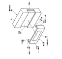
図1は、請求項1に記載の発明の一実施の形態であるガス警報器を、背面側から見て示す斜視図である。図2はその平面図、図3は側面図である。図示するとおり、この発明によるガス警報器は、図中符号10で示す警報器本体と図中符号11で示す取付板とで構成する。
【0011】
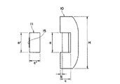
まず、警報器本体10は、まわりを、高さがH、幅がB、奥行きがDの外装ケースで被ってなり、その外装ケース12の背面側に凹部13を形成する。凹部13は、外装ケース12の中段位置に幅がa、深さがbで左右に設け、外装ケース12の左右側面にまでのばして背面から正面側に向けて長さcのところまで入り込ませてつくる。
【0012】
他方、取付板11は、樹脂材でつくり、幅が凹部13の幅a内にきっちりはまり込むa´、長さが警報器本体10の幅Bとほぼ同じB´、厚さが凹部13の深さbとほぼ同じb´のベース板部11aと、そのベース板部11aの両端内面側から長さcより若干短い長さc´に立ち上げた2つの弾性アーム部11b・11bと、その弾性アーム部11b・11bの先端に設ける爪状の掛止部11c・11cとで構成してなる。そして、ベース板部11aの外面に両面接着テープ15を貼り付けてなる。
【0013】
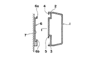
そして、このガス警報器を設置するときは、まず取付板11を持って両面接着テープ15の上紙を剥がし、ベース板部11aの外面を、設置する被取付面16に重ね合わせ、図4に示すように両面接着テープ15で貼り付けて取付板11を被取付面16に取り付ける。次いで、警報器本体10を持ってその凹部13位置を取付板11位置に合わせて取付板11の弾性アーム部11b・11bを見ながら図中矢示するごとく取付板11に近付け、該警報器本体10でそれら弾性アーム部11b・11bを押し開いてそれらの間に挿入する。
【0014】
そうして、正面側から警報器本体10を完全に押し込んだところで、凹部13内に丁度取付板11をはめ込み、凹部13終端に設ける左右の掛止凹部13a・13aにそれぞれ弾性アーム部11b・11bの掛止部11c・11cを掛け止めて弾性アーム部11b・11bで警報器本体10の外周を抱き、警報器本体10の背面および左右側面を取付板11の外面と段差なくつくって、結局図5に示すように警報器本体10を取付板11を介して壁面等の被取付面16に取り付ける。
【0015】
そして、長期間使用し、このガス警報器の保証期間が経過したときは、弾性アーム部11bの先端と警報器本体10間にドライバー等を挿入し、弾性アーム11bをたわませて掛止凹部13aとの係合を解除し、警報器本体10を取り出して新しいものと交換し、再び同じ取付板11を用いて被取付面に取り付けて設置する。
【0016】
さて、上述した実施の形態では、両面接着テープ15を用いて被取付面16に貼り付け、ガス警報器を設置した。しかし、両面接着テープに限らず、たとえば木ねじなどを用いて被取付面16に取り付け、ガス警報器を設置するようにしてもよい。
【0017】
ところで、上述した実施の形態では、被取付面16に取付板11を取り付けてから、警報器本体10を取り付けるようにした。しかし、図6に示すように、工場出荷時は、警報器本体10に取付板11を取り付け、その取付板11の背面に両面接着テープ15を貼り付けた状態とし、設置するときには、包装箱から取り出し、両面接着テープ15の上紙を剥がしてその両面接着テープ15で貼り付け、警報器本体10を取付板11とともに組付け状態のまま被取付面16に取り付けるようにしてもよい。
【0018】
このようにすると、上紙を剥がして被取付面16に押し付けるだけでよいから、ガス警報器の設置作業性を一層向上することができる。
【0019】
請求項2に記載の発明は、上述した図示実施の形態に示すとおり、警報器本体10に、取付板11がはまり込む凹部13を形成してなる、ことを特徴とする。そして、設置時、凹部13内に取付板11をきっちりはめ込んで全体を外観上一体化し、設置したガス警報器の被取付面16からの浮き上がりをなくして美観を向上することができる。
【0020】
請求項3に記載の発明は、上述した図示実施の形態に示すとおり、取付板11を被取付面16に取り付ける両面接着テープ15を、ベース板部11aの外面に貼り付けてなる、ことを特徴とする。そして、両面接着テープ15を用いてベース板部11aの外面を被取付面16に貼り付け、ガス警報器の取り付けを容易とすることができる。
【0021】
【発明の効果】
したがって、請求項1に記載の発明によれば、取付板の弾性アーム部を見ながら警報器本体を取り付けるから、両者の位置関係を把握しやすく、しかも正面側から弾性アーム部を押し開いて取り付けるだけであるから、ガス警報器の設置を迅速かつ確実に行うことができ、設置作業性を向上することができる。また、警報器本体の交換も容易であり、さらに横向きに取り付けても、がたなくしっかりと固定することができる。
【0022】
請求項2に記載の発明によれば、設置時、警報器本体の凹部内に取付板をきっちりはめ込んで全体を外観上一体化するから、被取付面からの浮き上がりをなくして美観を向上することができる。
【0023】
請求項3に記載の発明によれば、上紙を剥がすだけで両面接着テープで貼り付けて取付板を被取付面に取り付けるから、ガス警報器の取り付けを一層容易とすることができる。
【図面の簡単な説明】
【図1】請求項1に記載の発明の一実施の形態であるガス警報器を、背面側から見て示す斜視図である。
【図2】その平面図である。
【図3】その側面図である。
【図4】該ガス警報器において、被取付面に取り付けた取付板への警報器本体の取り付けを説明する横断面図である。
【図5】その取り付け後の状態を示す側面図である。
【図6】該ガス警報器の他の設置の仕方を説明するガス警報器を、背面側から見て示す斜視図である。
【図7】従来のガス警報器の設置の仕方を説明する説明縦断面図である。
【図8】従来の他のガス警報器の設置の仕方を説明する説明縦断面図である。
【符号の説明】
10 警報器本体
11 取付板
11a ベース板部
11b 弾性アーム部
11c 掛止部
13 凹部
15 両面接着テープ
16 被取付面[0001]
BACKGROUND OF THE INVENTION
The present invention relates to a gas alarm that issues an alarm when a gas leak is detected. Specifically, the present invention relates to a gas alarm device of a type in which an alarm device main body is attached to a surface to be attached such as a wall surface via an attachment plate.
[0002]
[Prior art]
Conventionally, a gas alarm device needs to be replaced with a new one when a certain warranty period (for example, 5 years) has passed after installation. For this reason, it is necessary to attach to a to-be-attached surface, such as a wall surface, easily to some extent. Therefore, some conventional gas alarm devices are composed of an alarm device main body and a mounting plate, and the alarm device main body is mounted on a mounting surface via the mounting plate. Then, after the warranty period has elapsed, the main body of the alarm is removed from the mounting plate and replaced with a new one, and is again mounted on the mounting surface using the same mounting plate.
[0003]
For example, as shown in FIG. 7,
[0004]
For example, as shown in FIG. 8, a fitting hole 8 is formed in the lower back of the
[0005]
[Problems to be solved by the invention]
However, with such a conventional gas alarm device,
▲ 1 ▼ When installing a gas alarm especially in a narrow place, it is hidden from the alarm
(2) Further, since the
[0006]
[Means for Solving the Problems]
Therefore, the invention described in
A
The mounting plate 11 that is aligned with the
[0007]
The invention according to
[0008]
The invention according to
[0009]
Then, the mounting plate 11 is mounted by superimposing the outer surface on the mounted
[0010]
DETAILED DESCRIPTION OF THE INVENTION
Hereinafter, embodiments of the present invention will be described with reference to the drawings.
FIG. 1 is a perspective view showing a gas alarm device according to an embodiment of the present invention as viewed from the back side. FIG. 2 is a plan view and FIG. 3 is a side view. As shown in the figure, the gas alarm device according to the present invention includes an alarm body indicated by
[0011]
First, the
[0012]
On the other hand, the mounting plate 11 is made of a resin material, the width a ′ fits exactly within the width a of the
[0013]
Then, when installing this gas alarm device, first hold the mounting plate 11 and peel off the top sheet of the double-sided
[0014]
Then, when the alarm device
[0015]
And when it is used for a long time and the warranty period of this gas alarm device has passed, a driver or the like is inserted between the tip of the elastic arm portion 11b and the
[0016]
Now, in the above-described embodiment, the gas alarm is installed by sticking to the mounting
[0017]
By the way, in embodiment mentioned above, after attaching the attachment board 11 to the to-
[0018]
If it does in this way, since it is only necessary to peel the upper paper and press it against the
[0019]
The invention described in
[0020]
The invention according to
[0021]
【The invention's effect】
Therefore, according to the first aspect of the present invention, the alarm device main body is mounted while observing the elastic arm portion of the mounting plate, so that it is easy to grasp the positional relationship between the two, and the elastic arm portion is attached by pushing open from the front side. Therefore, the gas alarm can be installed quickly and reliably, and the installation workability can be improved. In addition, it is easy to replace the alarm body, and even if it is mounted sideways, it can be fixed firmly without any hesitation.
[0022]
According to the second aspect of the present invention, when installed, the mounting plate is fitted into the recess of the alarm device body so that the whole is integrated in appearance, so that lifting from the mounted surface is eliminated and aesthetics are improved. Can do.
[0023]
According to the third aspect of the invention, since the attachment plate is attached to the surface to be attached by simply attaching the attachment plate to the attachment surface by simply peeling off the upper paper, the gas alarm can be attached more easily.
[Brief description of the drawings]
1 is a perspective view showing a gas alarm device according to an embodiment of the present invention as viewed from the back side; FIG.
FIG. 2 is a plan view thereof.
FIG. 3 is a side view thereof.
FIG. 4 is a cross-sectional view illustrating attachment of the alarm body to a mounting plate attached to a mounting surface in the gas alarm device.
FIG. 5 is a side view showing a state after the attachment.
FIG. 6 is a perspective view showing a gas alarm device for explaining another installation method of the gas alarm device as viewed from the back side.
FIG. 7 is an explanatory longitudinal sectional view explaining how to install a conventional gas alarm device.
FIG. 8 is an explanatory longitudinal sectional view for explaining a method of installing another conventional gas alarm device.
[Explanation of symbols]
DESCRIPTION OF
Claims (3)
前記警報器本体の外装ケースの背面側に凹部を形成し、その凹部を左右に設けて前記外装ケースの左右側面にまでのばし、その左右側面にまでのばした前記凹部の終端に掛止凹部を設けるとともに、
前記凹部位置を位置合わせしてその凹部にはめ込む前記取付板に、外面を前記被取付面に重ね合わせて取り付けるベース板部と、そのベース板部の内面側から立ち上げて前記警報器本体の外周を抱く複数の弾性アーム部と、その弾性アーム部に設けて前記警報器本体に掛け止める掛止部とを設けてなる、ガス警報器。In the gas alarm that attaches the main body of the alarm to the mounting surface via the mounting plate,
A concave portion is formed on the back side of the outer case of the alarm device body, the concave portions are provided on the left and right sides and extended to the left and right side surfaces of the outer case, and a latching concave portion is provided at the end of the concave portion extended to the left and right side surfaces. While providing
A base plate portion that is attached to the mounting plate that is aligned with the concave portion and is fitted into the concave portion, and an outer surface is mounted on the mounting surface, and an outer periphery of the alarm body that is raised from the inner surface side of the base plate portion A gas alarm device comprising: a plurality of elastic arm portions that hold the inner surface of the alarm device; and a latch portion that is provided on the elastic arm portion and latches on the alarm device main body.
Priority Applications (1)
| Application Number | Priority Date | Filing Date | Title |
|---|---|---|---|
| JP27548296A JP3745845B2 (en) | 1996-09-26 | 1996-09-26 | Gas alarm |
Applications Claiming Priority (1)
| Application Number | Priority Date | Filing Date | Title |
|---|---|---|---|
| JP27548296A JP3745845B2 (en) | 1996-09-26 | 1996-09-26 | Gas alarm |
Publications (2)
| Publication Number | Publication Date |
|---|---|
| JPH10105854A JPH10105854A (en) | 1998-04-24 |
| JP3745845B2 true JP3745845B2 (en) | 2006-02-15 |
Family
ID=17556146
Family Applications (1)
| Application Number | Title | Priority Date | Filing Date |
|---|---|---|---|
| JP27548296A Expired - Lifetime JP3745845B2 (en) | 1996-09-26 | 1996-09-26 | Gas alarm |
Country Status (1)
| Country | Link |
|---|---|
| JP (1) | JP3745845B2 (en) |
Families Citing this family (5)
| Publication number | Priority date | Publication date | Assignee | Title |
|---|---|---|---|---|
| JP4638266B2 (en) * | 2005-03-31 | 2011-02-23 | 三和シヤッター工業株式会社 | Shutter having shutter case with alarm device |
| JP3832508B1 (en) * | 2006-03-01 | 2006-10-11 | オムロン株式会社 | Open / close detection device |
| JP5112253B2 (en) * | 2008-10-21 | 2013-01-09 | 理研計器株式会社 | Gas alarm device |
| JP2010140067A (en) * | 2008-12-09 | 2010-06-24 | Century Corp | Home fire alarm and installation structure for the same |
| CN108428329B (en) * | 2018-02-02 | 2023-05-12 | 江苏艾科半导体有限公司 | Portable detection alarm device for packaging tray of integrated circuit IC |
-
1996
- 1996-09-26 JP JP27548296A patent/JP3745845B2/en not_active Expired - Lifetime
Also Published As
| Publication number | Publication date |
|---|---|
| JPH10105854A (en) | 1998-04-24 |
Similar Documents
| Publication | Publication Date | Title |
|---|---|---|
| JPS585202U (en) | Mounting structure of vehicle lamp housing | |
| JP3745845B2 (en) | Gas alarm | |
| JP2528112Y2 (en) | Blind head rail cover | |
| JP2001020444A (en) | Coupling construction between wall panel and ceiling panel for bathroom or the like | |
| JP3849243B2 (en) | Pin hook | |
| JPS6341954Y2 (en) | ||
| JP2606463Y2 (en) | Clip mounting seat | |
| CN210888363U (en) | Door lock | |
| JPH0425030Y2 (en) | ||
| JPH0743423Y2 (en) | Thermal insulation parting for building openings, etc. | |
| JP2581189Y2 (en) | Spring lid holder for fuel lid | |
| JP2599922Y2 (en) | lighting equipment | |
| JPH0386621A (en) | Molding installation structure | |
| JPH0637205Y2 (en) | Car trim retainer | |
| JPS5855489Y2 (en) | Card holder mounting structure | |
| JP2528820Y2 (en) | Mailbox with nameplate | |
| JPH06319614A (en) | Fitting structure for cover member | |
| JPH0446973Y2 (en) | ||
| JPH0430626Y2 (en) | ||
| JPH0349071Y2 (en) | ||
| JPS5920517Y2 (en) | lock | |
| JPS6343497Y2 (en) | ||
| JPS6325245Y2 (en) | ||
| JPH0639014Y2 (en) | Cover for pillar locking hole of storage unit | |
| JPH056694Y2 (en) |
Legal Events
| Date | Code | Title | Description |
|---|---|---|---|
| A131 | Notification of reasons for refusal |
Free format text: JAPANESE INTERMEDIATE CODE: A131 Effective date: 20050816 |
|
| A521 | Written amendment |
Free format text: JAPANESE INTERMEDIATE CODE: A523 Effective date: 20051017 |
|
| TRDD | Decision of grant or rejection written | ||
| A01 | Written decision to grant a patent or to grant a registration (utility model) |
Free format text: JAPANESE INTERMEDIATE CODE: A01 Effective date: 20051118 |
|
| A61 | First payment of annual fees (during grant procedure) |
Free format text: JAPANESE INTERMEDIATE CODE: A61 Effective date: 20051118 |
|
| R150 | Certificate of patent or registration of utility model |
Free format text: JAPANESE INTERMEDIATE CODE: R150 |
|
| FPAY | Renewal fee payment (event date is renewal date of database) |
Free format text: PAYMENT UNTIL: 20081202 Year of fee payment: 3 |
|
| FPAY | Renewal fee payment (event date is renewal date of database) |
Free format text: PAYMENT UNTIL: 20091202 Year of fee payment: 4 |
|
| FPAY | Renewal fee payment (event date is renewal date of database) |
Free format text: PAYMENT UNTIL: 20091202 Year of fee payment: 4 |
|
| FPAY | Renewal fee payment (event date is renewal date of database) |
Free format text: PAYMENT UNTIL: 20101202 Year of fee payment: 5 |
|
| FPAY | Renewal fee payment (event date is renewal date of database) |
Free format text: PAYMENT UNTIL: 20101202 Year of fee payment: 5 |
|
| FPAY | Renewal fee payment (event date is renewal date of database) |
Free format text: PAYMENT UNTIL: 20111202 Year of fee payment: 6 |
|
| FPAY | Renewal fee payment (event date is renewal date of database) |
Free format text: PAYMENT UNTIL: 20121202 Year of fee payment: 7 |
|
| FPAY | Renewal fee payment (event date is renewal date of database) |
Free format text: PAYMENT UNTIL: 20131202 Year of fee payment: 8 |
|
| EXPY | Cancellation because of completion of term |