JP3745146B2 - Recording device - Google Patents
Recording device Download PDFInfo
- Publication number
- JP3745146B2 JP3745146B2 JP37344998A JP37344998A JP3745146B2 JP 3745146 B2 JP3745146 B2 JP 3745146B2 JP 37344998 A JP37344998 A JP 37344998A JP 37344998 A JP37344998 A JP 37344998A JP 3745146 B2 JP3745146 B2 JP 3745146B2
- Authority
- JP
- Japan
- Prior art keywords
- recording
- recording material
- carriage
- roller
- driving roller
- Prior art date
- Legal status (The legal status is an assumption and is not a legal conclusion. Google has not performed a legal analysis and makes no representation as to the accuracy of the status listed.)
- Expired - Fee Related
Links
Images


Description
【0001】
【発明の属する技術分野】
本発明は、記録ヘッドから被記録材へインクを吐出して被記録材に記録を行うインクジェット方式の記録装置に関する。
【0002】
【従来の技術】
プリンター、複写機、ファクシミリなどの機能を有する記録装置、あるいはコンピューターやワードプロセッサなどを含む複合機やワークステーションの出力機器として用いられる記録装置は、画像情報に基づいて用紙やプラスチック薄板(OHP用のものなど)などの被記録材(記録媒体)に、文字や記号などを含む画像を記録するように構成されている。このような記録装置は、使用する記録手段の記録方式により、インクジェット式、ワイヤドット式、感熱式、熱転写式、レーザービーム式などに分けることができる。
【0003】
被記録材の搬送方向(副走査方向)と交差する方向に主走査する記録方式を採用したシリアルタイプの記録装置においては、被記録材を所定の記録位置にセットした後、被記録材に沿って移動(主走査)する保持部材としてのキャリッジ上に搭載された記録手段としての記録ヘッドによって、文字や記号などを含む画像を被記録材に記録する。被記録材への1行分の記録を終了した後に所定の量だけ被記録材の紙送り(副走査)を行ない、その後、次の行の画像を記録するという動作を繰り返すことにより、被記録材の所望の範囲に画像が記録される。
【0004】
一方、被記録材を搬送方向に送るという副走査のみで画像を記録するラインタイプの記録装置においては、被記録材を所定の記録位置にセットし、一括して1行分の記録を連続的に行なうごとに所定量の紙送り(ピッチ送り)を行なっていくことで、被記録材の全体に画像が記録される。
【0005】
上述した記録手段の記録方式のうちインクジェット式は、記録手段としての記録ヘッドから被記録材にインクを吐出して記録を行なうものであり、記録ヘッドのコンパクト化が容易である。また、インクジェット式を採用したインクジェット記録装置は、高精細な画像を高速で記録することができ、普通紙に特別の処理を必要とせずに記録することができる。その上、ランニングコストが安く、ノンインパクト方式であるため騒音が少なく、しかも、多色のインクを使用してカラー画像を記録することが容易であるなどの利点を有している。
【0006】
インクジェット式の記録ヘッドには、インクなどの液体を吐出する吐出口が形成されており、その吐出口から被記録材に向けてインクを吐出することで被記録材に記録が行われる。このように、記録ヘッドから、被記録材である記録用紙などへインク滴を飛翔させて記録を行うインクジェット記録装置においては、記録ヘッドの吐出口から記録用紙までの距離を一定にすることが重要であり、比較的、記録用紙の近距離で吐出口からインク滴を飛翔させて記録することが好ましい。それは、記録ヘッドの吐出口から記録用紙までの距離が離れるほどインクの吐出方向のばらつきに誤差がでるため、記録用紙における画像の記録位置のばらつきがでてしまうからである。
【0007】
図12は、従来の記録装置を模式的に示す断面図である。図12に示すように従来の記録装置の本体101では、筐体101bの一方の端部に、回転軸114によって自動給紙トレー112の一方の端部が取り付けられている。自動給紙トレー112は、その回転軸114によって回転軸114を中心に回動可能に支持されている。また、自動給紙トレー112の他方の端部はトレー加圧ばね113によって上方に付勢されており、自動給紙トレー112の上面には、本体101の内部に給送されるシート状の被記録材110が複数枚積層されている。
【0008】
自動給紙トレー112の上方には、一方向に回転可能に支持されたDカットローラ115が備えられている。Dカットローラ115の形状は、円柱状のものを、その円柱の側面の一部が円柱の中心軸と平行な平面となるように切断したものであり、Dカットローラ115の、Dカットローラ115の中心軸に対して垂直な方向の断面形状がD字形となっている。Dカットローラ115は、自動給紙トレー112上の被記録材110を本体101内の記録領域に向けて1枚ずつ自動的に送り出すためのものである。このDカットローラ115は、筐体101b内の備えられた1回転クラッチ(不図示)により、矢印Bに示される方向に必要な時に1回転させられ、Dカットローラ115の回転に伴って自動給紙トレー112上の最も上層の被記録材110が、後述する駆動ローラ103に向けて本体101の内部へと搬送される。この図12では、自動給紙トレー112上の複数の被記録材110のうち、最上層にあった被記録材111が本体101の内部に給送された状態が示されている。
【0009】
Dカットローラ115により自動給紙トレー112から搬送される被記録材の搬送方向下流側には、一端部が上ガイド支持軸108により回動可能に支持された上ガイド107と、Dカットローラ115により搬送された被記録材111を副走査方向に搬送するために回転する駆動ローラ103と、駆動ローラ103の上方に配置されるように上ガイド107に取り付けられた従動ローラ106とが備えられている。上ガイド107は被記録材111の搬送経路の上側に配置されており、上ガイド107における被記録材111の搬送方向上流側の端部が上ガイド支持軸108により支持されている。また、上ガイド107は押さえばね109によって下方に、すなわち図12において上ガイド107が上ガイド支持軸108を中心に反時計回転方向に回転するように付勢されている。この上ガイド107のほぼ中央部に従動ローラ106が従動ローラ106の中心軸を中心に回動可能に取り付けられている。従って、押さえばね109による上ガイド107への付勢力によって、従動ローラ106が、駆動ローラ103と圧接するように駆動ローラ103に向かう方向に付勢されている。
【0010】
従動ローラ106は上ガイド107と共に上ガイド支持軸108を中心に回動可能、すなわち従動ローラ106は揺動可能となっており、従動ローラ106が、駆動ローラ103から離れる方向に変位することにより、従動ローラ106と駆動ローラ103との間に被記録材111が挟み込まれる。駆動ローラ103が矢印Dの方向に回転しつつ従動ローラ106と駆動ローラ103との間に被記録材111が挟み込まれることで被記録材111に搬送力が与えられる。駆動ローラ103と従動ローラ106との間に何も挟み込まれていない時には、従動ローラ106が押さえばね109の付勢力によって駆動ローラ103と圧接している。
【0011】
また、筐体101bの内部における被記録材111の搬送経路の上方には、被記録材111の搬送方向と交差する方向に延びる、互いに平行なキャリッジ摺動軸120および位置決めレール121が配置されている。キャリッジ摺動軸120および位置決めレール121は、互いに所定の距離をおいた状態で筐体101bに固定されている。摺動軸120の、摺動軸120に対して垂直な方向の断面形状は円形となっている。これらキャリッジ摺動軸120および位置決めレール121によって、記録手段を搭載するための保持部材であるキャリッジ122が被記録材111の搬送方向と交差する方向、すなわち主走査方向に摺動可能に支持されている。キャリッジ122には、記録手段である記録ヘッド123が着脱可能に搭載されている。記録ヘッド123は、図13に基づいて後述する機構によってキャリッジ122に対して精度よく位置決めされて固定されている。記録ヘッド123の一面には、インクなどの液体を吐出する吐出口が形成されており、キャリッジ122に記録ヘッド123を搭載した際に、記録ヘッド123の吐出口面が記録ヘッド123の下面に位置する。記録ヘッド123が搭載されたキャリッジ122をキャリッジ摺動軸120および位置決めレール121と平行な方向に摺動させることにより記録の主走査が行われる。
【0012】
被記録材111の搬送経路における駆動ローラ103よりも下流側には、被記録材111の搬送経路を規定する下ガイド板102が固定されている。下ガイド板102の一部の上面は、キャリッジ122に搭載された記録ヘッド123の吐出口面と対向している。下ガイド板102は、記録ヘッド123の下方を被記録材111が通過する際に記録ヘッド123の吐出口から被記録材111の記録ヘッド123側の表面までの距離Aを規定するための、記録装置における被記録材の通過基準となるものである。駆動ローラ103と従動ローラ106との間に挟まれて搬送経路の下流側に搬送された被記録材111は、上ガイド107により下方に向けて押圧されて被記録材111の下面が下ガイド板102の上面と接触しながら、下ガイド板102に沿って下流側に給送される。このように被記録材111が下ガイド板102に沿って記録ヘッド123の下方を通過することで、記録ヘッド123の吐出口から被記録材111の記録ヘッド123側の表面までの距離Aが一定に保たれる。
【0013】
さらに、本体101内の被記録材111の搬送経路における記録ヘッド123よりも下流側には、記録ヘッド123によって記録された被記録材111を、図12の矢印Cに示される方向に向けて本体101の外部に排出するための排出駆動ローラ104および拍車ローラ105が備えられている。被記録材111の搬送経路の下側に排出駆動ローラ104が配置され、その搬送経路の上側に拍車ローラ105が配置されており、拍車ローラ105は、不図示の付勢部材により排出駆動ローラ104側に向けて付勢されている。排出駆動ローラ104は駆動ローラ103と同期して回転させられ、排出駆動ローラ104と拍車ローラ105との間に被記録材111が挟み込まれることにより、被記録材111を本体101の外部に排出するための、被記録材111への搬送力が発生する。ここで、拍車ローラ105の形状が拍車状となり、拍車ローラ105が被記録材111の記録ヘッド123側の面と接することによって、記録ヘッド123により被記録材111に付着したインクのかすれが防止される。排出駆動ローラ104と拍車ローラ105との間に何も挟み込まれていない時には、拍車ローラ105は前記付勢部材によって排出駆動ローラ104と圧接している。
【0014】
このように構成された従来の記録装置では、自動給紙トレー112上の複数の被記録材110のうち最も上層の被記録材が、適宜、Dカットローラ115の1回転により自動給紙トレー112から駆動ローラ103へと給送される。駆動ローラ103へ給送された被記録材111は、下ガイド板102に沿って記録ヘッド123の下方、すなわち記録ヘッド123の吐出口の近傍を通過するように搬送され、排出駆動ローラ104および拍車ローラ105によって本体101の外部に搬出される。このように本体101の内部で被記録材111が搬送される間、記録ヘッド123はキャリッジ122によって被記録材111の搬送方向と交差する方向に移動しつつ画像データに基づくインクの吐出を行い、被記録材111に文字や絵などの画像を記録する。
【0015】
図13は、図12に示した記録装置の本体101内のキャリッジ122の構成を説明するための斜視図である。図13に示すように、キャリッジ122の上部、すなわち位置決めレール121側の部分には、記録ヘッド123がキャリッジ122から抜け出ることを防止しして記録ヘッド123をキャリッジ122に着脱可能に固定するためのレバー122aが備えられている。このレバー122aによって記録ヘッド123がキャリッジ122に対して精度よく位置決めされて固定されている。キャリッジ122の、位置決めレール121への取付け部には、位置決めレール121に対してキャリッジ122をがたなく摺動させるためのばね部材122bが取り付けられている。ばね部材122bによって、キャリッジ122の位置決めレール121側の部分が、位置決めレール121から離れる方向に付勢されている。
【0016】
【発明が解決しようとする課題】
しかしながら、従来のインクジェット記録装置では、厚さの異なる記録用紙に記録を行う場合に、記録ヘッドの吐出口から記録用紙までの距離が、記録用紙の厚さに応じて記録用紙ごとに異なり、記録用紙に記録される画像の品位が損なわれるという問題点がある。また、厚い被記録材に記録を行う際には、記録ヘッドにより記録が行われる記録部をその厚い被記録材が通るときに、被記録材の厚さの違いにより、記録ヘッドの吐出口にその被記録材が接触してしまうことすら生じた。
【0017】
また、複数の記録用紙の厚さがそれぞれ異なることによる画像品位の低下を防止するために、被記録材の記録側の面を基準に被記録材の搬送通路を構成するような試みもなされているが、被記録材が薄い紙の場合などには被記録材と記録ヘッドとの間隔を一定に保つことができなく、吐出口から記録用紙までの距離を一定に保つことが上手くいかなかった。従って、従来のインクジェット記録装置では、これらの問題点を解決する手段が特になく、被記録材の厚みが異なった場合でも、記録ヘッドの吐出口から被記録材までの距離をより安定させることが困難であった。
【0018】
このため、たとえ、記録ヘッドの主走査方向の移動、および被記録材の副走査方向の搬送を高精度に行っても、インク滴の飛び出す方向のばらつきが、インク滴の飛ぶ距離の変化に応じて増幅されてインクの着地点がばらつき、画像の高精細度が損なわれるという問題点があった。
【0019】
本発明の目的は、厚さの異なる複数種の被記録材に記録を行う場合でも、記録ヘッドの吐出口から被記録材までの距離を、被記録材の厚さに依存させることなく一定に保つことにより、高精細の画像を高精度で記録することが可能な記録装置を提供することにある。
【0020】
【課題を解決するための手段】
上記目的を達成するために、本発明は、液体を吐出する吐出口が形成され、前記吐出口からシート状の被記録材に向けて液体を吐出することで前記被記録材に記録を行う記録手段を搭載するための保持部材と、一直線上を往復移動可能となるように前記保持部材を摺動可能に支持する摺動軸と、前記記録手段の前記吐出口の近傍を前記被記録材が通るように前記被記録材を搬送するために回転する駆動ローラとを有する記録装置において、前記駆動ローラと圧接するように前記駆動ローラ側に付勢され前記駆動ローラから離れる方向に変位して前記駆動ローラとの間に前記被記録材を挟み込むことで前記被記録材に搬送力を与えるための従動ローラを有し、前記摺動軸の一端側に配され前記従動ローラの変位量から前記被記録材の厚さを検出する検出手段と、前記検出手段により検出された前記被記録材の厚さの検出結果に基づいて前記記録手段の前記吐出口を前記被記録材に対して略垂直な方向に変位させる変位手段と、前記変位手段により前記記録手段の前記吐出口が変位した際に前記吐出口から前記被記録材までの距離を保持する保持手段とを備える。そして、前記変位手段は、前記従動ローラの変位量に応じて変位する係合溝と、前記保持部材が前記検出手段に近づく方向に移動したときに前記係合溝に係合することによって前記吐出口を変位させる係合突部とを有する。また、前記保持手段は、前記保持部材と一体的に移動可能であり、前記保持部材が前記検出手段から離れる方向に移動して、前記係合突部が前記係合溝と係合しなくなった状態でも前記吐出口から前記被記録材までの距離を保持する。
【0021】
上記の発明では、保持部材に搭載された記録手段によって記録されるシート状の被記録材の厚さが検出手段により検出されることで、その検出結果に基づいて記録手段の吐出口が変位手段によって被記録材に対して略垂直な方向に変位され、吐出口が変位した際の吐出口から被記録材までの距離が保持手段により保持される。このように、被記録材の厚さに応じて吐出口を変位手段によって変位させて吐出口と被記録材との距離を被記録材の厚さに対して適正な値に設定し、その吐出口と被記録材との距離が保持手段により保持された状態で、検出手段により厚さを検出した被記録材に対して記録手段によって記録が行われる。従って、厚さが異なる複数の被記録材に対して記録を行う場合でも、被記録材の厚さに応じて記録手段の吐出口を変位させることで吐出口と被記録材との距離を常に適正な値に一定に保つことができ、記録手段によって被記録材に高精度の画像を記録することが可能となる。
【0022】
具体的には、記録装置が、前記記録手段の前記吐出口の近傍を前記被記録材が通るように前記被記録材を搬送するために回転する駆動ローラと、前記駆動ローラと圧接するように前記駆動ローラ側に付勢され、前記駆動ローラから離れる方向に変位して前記駆動ローラとの間に前記被記録材を挟み込むことで前記被記録材に搬送力を与えるための従動ローラとをさらに有しており、前記検出手段が、前記従動ローラの変位量から前記被記録材の厚さを検出するものである。この場合、前記駆動ローラと圧接するように前記駆動ローラ側に付勢された前記従動ローラが、前記被記録材の搬送方向と直行する方向に並列に複数配置されており、前記検出手段が、複数の前記従動ローラのうち、前記被記録材における搬送基準となる側部に近い従動ローラの変位量から前記被記録材の厚さを検出するものである。
【0023】
上記のように、被記録材の厚さを検出する検出手段が、被記録材を搬送するための駆動ローラ側に付勢された従動ローラの変位量から厚さを検出するものであることにより、簡単な構成で被記録材の厚さを検出することが可能な検出手段が得られる。また、検出手段が、複数の従動ローラのうち、被記録材における搬送基準となる側部に近い従動ローラの変位量から被記録材の厚さを検出するものであることにより、大きさの異なる被記録材に対しても、簡単な構成で被記録材の厚さを検出ことが可能な検出手段を得ることができる。
【0024】
また、前記変位手段が、前記摺動軸を中心に前記保持部材を回転させることで前記記録手段の前記吐出口を前記被記録材に対して略垂直な方向に変位させるものであることが好ましい。
【0028】
【発明の実施の形態】
次に、本発明の実施の形態について図面を参照して説明する。
【0029】
(実施の形態)図1は、本発明の実施形態の記録装置を模式的に示す断面図である。図1に示すように本実施形態の記録装置の本体1では、筐体1bの一方の端部に、回転軸14によって自動給紙トレー12の一方の端部が取り付けられている。自動給紙トレー12は、その回転軸14によって回転軸14を中心に回動可能に支持されている。また、自動給紙トレー12の他方の端部はトレー加圧ばね13によって上方に付勢されており、自動給紙トレー12の上面には、本体1の内部に給送されるシート状の被記録材10が複数枚積層されている。
【0030】
自動給紙トレー12の上方には、一方向に回転可能に支持されたDカットローラ15が備えられている。Dカットローラ15の形状は、円柱状のものを、その円柱の側面の一部が円柱の中心軸と平行な平面となるように切断したものであり、Dカットローラ15の、Dカットローラ15の中心軸に対して垂直な方向の断面形状がD字形となっている。Dカットローラ15は、自動給紙トレー12上の被記録材10を本体1内の記録領域に向けて1枚ずつ自動的に送り出すためのものである。このDカットローラ15は、筐体1b内の備えられた1回転クラッチ(不図示)により、矢印Bに示される方向に必要な時に1回転させられ、Dカットローラ15の回転に伴って自動給紙トレー12上の最も上層の被記録材10が、後述する駆動ローラ3に向けて本体1の内部へと搬送される。この図1では、自動給紙トレー12上の複数の被記録材10のうち、最上層にあった被記録材11が本体1の内部に給送された状態が示されている。
【0031】
Dカットローラ15により自動給紙トレー12から搬送される被記録材の搬送方向下流側には、一端部が上ガイド支持軸8により回動可能に支持された上ガイド7と、Dカットローラ15により搬送された被記録材11を副走査方向に搬送するために回転する駆動ローラ3と、駆動ローラ3の上方に配置されるように上ガイド7に取り付けられた従動ローラ6とが備えられている。上ガイド7は、被記録材11の搬送経路の上側に配置されており、上ガイド7における被記録材11の搬送方向上流側の端部が上ガイド支持軸8により支持されている。また、上ガイド7は押さえばね9によって下方に、すなわち図1において上ガイド7が上ガイド支持軸8を中心に反時計回転方向に回転するように付勢されている。この上ガイド7のほぼ中央部に従動ローラ6が従動ローラ6の中心軸を中心に回動可能に取り付けられている。従って、押さえばね9による上ガイド7への付勢力によって、従動ローラ6が、駆動ローラ3と圧接するように駆動ローラ3側に付勢されている。
【0032】
従動ローラ6は上ガイド7と共に上ガイド支持軸8を中心に回動可能、すなわち従動ローラ6は揺動可能となっており、従動ローラ6が、駆動ローラ3から離れる方向に変位することにより、従動ローラ6と駆動ローラ3との間に被記録材11が挟み込まれる。駆動ローラ3が矢印Dの方向に回転しつつ従動ローラ6と駆動ローラ3との間に被記録材11が挟み込まれることで被記録材11に搬送力が与えられる。駆動ローラ3と従動ローラ6との間に何も挟み込まれていない時には、従動ローラ6が押さえばね9の付勢力によって駆動ローラ3と圧接している。
【0033】
また、筐体1bの内部における被記録材11の搬送経路の上方には、被記録材11の搬送方向と交差する方向に延びる、互いに平行なキャリッジ摺動軸20および位置決めレール21が配置されている。キャリッジ摺動軸20および位置決めレール21は、互いに所定の距離をおいた状態で筐体1bに固定されている。摺動軸20および位置決めレール21の、摺動軸20および位置決めレール21に対して垂直な方向の断面形状は円形となっている。これらのキャリッジ摺動軸20および位置決めレール21によって、記録手段を搭載するための保持部材であるキャリッジ22が被記録材11の搬送方向と交差する方向、すなわち主走査方向に摺動可能に支持されている。キャリッジ摺動軸20には、キャリッジ22の下部が直接取り付けられ、位置決めレール21にはキャリッジ22の上部が、後述するように摺動部材32や位置記憶レバー31を介して取り付けられている。
【0034】
キャリッジ22には、記録手段である記録ヘッド23が着脱可能に搭載されている。記録ヘッド23の一面には、インクなどの液体を吐出する吐出口が形成されており、記録ヘッド23は、図2に基づいて後述する機構によってキャリッジ22に対して精度よく位置決めされて固定されている。キャリッジ22に記録ヘッド23を搭載した際に、記録ヘッド23の吐出口面が記録ヘッド23の下面に位置する。記録ヘッド23が搭載されたキャリッジ22をキャリッジ摺動軸20および位置決めレール21と平行な方向に摺動させることにより記録の主走査が行われる。
【0035】
被記録材11の搬送経路における駆動ローラ3よりも下流側には、被記録材11の搬送経路を規定する下ガイド板2が固定されている。下ガイド板2の一部の上面は、キャリッジ22に搭載された記録ヘッド23の吐出口面と対向している。この下ガイド板2は、記録ヘッド23の下方を被記録材11が通過する際に記録ヘッド23の吐出口から被記録材11の記録ヘッド23側の表面までの距離Aを規定するための、記録装置における被記録材の通過基準となるものである。駆動ローラ3と従動ローラ6との間に挟まれて搬送経路の下流側に搬送された被記録材11は、上ガイド7により下方に向けて押圧されて被記録材11の下面が下ガイド板2の上面と接触しながら、下ガイド板2に沿って下流側に給送される。このように被記録材11が下ガイド板2に沿って記録ヘッド23の下方を通過することで、記録ヘッド23の吐出口から被記録材11の記録ヘッド23側の表面までの距離Aが一定に保たれる。
【0036】
さらに、本体1内の被記録材11の搬送経路における記録ヘッド23よりも下流側には、記録ヘッド23によって記録された被記録材11を、図1の矢印Cに示される方向に向けて本体1の外部に排出するための排出駆動ローラ4および拍車ローラ5が備えられている。被記録材11の搬送経路の下側に排出駆動ローラ4が配置され、その搬送経路の上側に拍車ローラ5が配置されており、拍車ローラ5は、不図示の付勢部材により排出駆動ローラ4側に向けて付勢されている。排出駆動ローラ4は駆動ローラ3と同期して回転させられ、排出駆動ローラ4と拍車ローラ5との間に被記録材11が挟み込まれることにより、被記録材11を本体1の外部に排出するための、被記録材11への搬送力が発生する。ここで、拍車ローラ5の形状が拍車状となり、拍車ローラ5が被記録材11の記録ヘッド23側の面と接することによって、記録ヘッド23により被記録材11に付着したインクのかすれが防止される。排出駆動ローラ4と拍車ローラ5との間に何も挟み込まれていない時には、拍車ローラ5は前記付勢部材によって排出駆動ローラ4と圧接している。
【0037】
このように構成された本実施形態の記録装置では、自動給紙トレー12上の複数の被記録材10のうち最も上層の被記録材が、適宜、Dカットローラ15の1回転により自動給紙トレー12から駆動ローラ3へと給送される。駆動ローラ3へ給送された被記録材11は、下ガイド板2に沿って記録ヘッド23の下方、すなわち記録ヘッド23の吐出口の近傍を通過するように搬送され、排出駆動ローラ4および拍車ローラ5によって本体1の外部に搬出される。このように本体1の内部で被記録材11が搬送される間、記録ヘッド23はキャリッジ22によって被記録材11の搬送方向と交差する方向に移動しつつ画像データに基づくインクの吐出を行い、被記録材11に文字や絵などの画像を記録する。
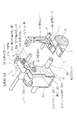
【0038】
図2は、図1に示した記録装置の内部の構成について説明するための斜視図である。図1および図2に示すように、キャリッジ22を支持するための摺動部材32は位置決めレール21によって、位置決めレール21と平行な方向に摺動可能に支持されている。上述したように位置決めレール21の断面形状は円形であり、摺動部材32が位置決めレール21の中心軸を中心に回動可能となっている。摺動部材32には、一方向に延びる板状のキャリッジ支持部32aが形成されており、キャリッジ支持部32の先端部分に長穴32cが形成されている。この長穴32cに係合するスライドピン22cが、キャリッジ22の、主走査方向に対して垂直な両側面のそれぞれに形成されている。従って、キャリッジ22の両側面のそれぞれに配置されるキャリッジ支持部32aが2つ、摺動部材32に形成されており、それぞれのキャリッジ支持部32aに、それぞれのキャリッジ支持部32aに対応するスライドピン22cが係合する長穴22cが形成されている。
【0039】
キャリッジ摺動軸20にキャリッジ22の下部を取り付け、キャリッジ22の上部を摺動部材32を介して位置決めレール21に取り付けた際に、長穴32cの長手方向が水平方向とほぼ平行となるように長穴32cが形成されている。スライドピン22cの形状は円柱であり、スライドピン22cが、長穴32cの内部でスライドピン22cの中心軸を中心に回動可能、かつ、長穴32cの内部で長穴32cの長手方向にスライド可能となっている。このように一対のスライドピン22cのそれぞれが、それぞれのスライドピン22cに対応する長穴32cに係合し、かつ、摺動部材32が位置決めレール21の中心軸を中心に回動可能となっていることにより、長穴32c内をスライドピン22cがスライドする範囲内でキャリッジ22がキャリッジ摺動軸20の中心軸を中心に回動可能となっている。キャリッジ22は、不図示の第1の付勢手段により摺動部材32から離れる方向に付勢されている。例えば、キャリッジ22と摺動部材32との間に第1の付勢手段としてばねなどを取り付け、そのばねによりキャリッジ22と摺動部材32とが互いに離れるような方向にキャリッジ22と摺動部材32のそれぞれに押圧力を加える。このような第1の付勢手段によって、キャリッジ22の上部が摺動部材32から離れる方向となる一方の方向にキャリッジ摺動軸20の中心軸を中心にキャリッジ22が回転するようにキャリッジ22が付勢されている。
【0040】
また、キャリッジ22の摺動部材32側の側壁の上部には、位置決めレール21と平行な回転軸22bが形成されている。回転軸22bには、位置記憶レバー31の一端部が回転軸22bを中心に回動可能に取り付けられている。位置記憶レバー31の一部の下面は摺動部材32の上面と対向しており、位置記憶レバー31は不図示の第2の付勢手段により、図2の矢印Eに示される方向、すなわち摺動部材32側に向かう方向に付勢されている。
【0041】
摺動部材32の上面には、その面から突出し、かつ、主走査方向に延びる歯として山形部が複数形成されており、それら複数の山形部から第1の噛み合い部32bが構成されている。第1の噛み合い部32bのそれぞれの山形部におけるキャリッジ22側と反対側の面は、キャリッジ22下方の被記録材11に対してほぼ垂直な垂直面となり、それぞれの山形部におけるキャリッジ22側の面は、キャリッジ22下方の被記録材11に対して傾斜した傾斜面となっている。
【0042】
一方、位置記憶レバー31の下面、すなわち摺動部材32側の面には、第1の噛み合い部32bのそれぞれの歯と噛み合う歯として、その面から突出し、かつ、主走査方向に延びる山形部が複数形成されており、それら複数の山形部から第2の噛み合い部31bが構成されている。第2の噛み合い部31bのそれぞれの山形部における回転軸22b側の面は、キャリッジ22下方の被記録材11に対してほぼ垂直な垂直面となり、それぞれの山形部における回転軸22b側と反対側の面は、キャリッジ22下方の被記録材11に対して傾斜した傾斜面となっている。
【0043】
第1の噛み合い部32bおよび第2の噛み合い部31bのそれぞれの山形部は、キャリッジ22がキャリッジ摺動軸20の中心軸を中心に摺動部材32側と反対側に向かって一方の方向に回転する動作を規制するためのものである。第1の噛み合い部32bおよび第2の噛み合い部31bと、前記第2の付勢手段とから一方向ラッチ機構が構成されている。この一方向ラッチ機構では、第1の噛み合い部32bと第2の噛み合い部31bのそれぞれの歯が上述したような形状に形成されていることにより、第1の噛み合い部32bと第2の噛み合い部31bとが噛み合った状態で、キャリッジ22がキャリッジ摺動軸20の中心軸を中心に摺動部材32側と反対側に向かって回転する動作が規制される。また、第1の噛み合い部32bと第2の噛み合い部31bとが噛み合った状態では、位置記憶レバー31が、キャリッジ22側に向かう方向と反対の方向、すなわち図2の矢印Fに示される方向に付勢された際にそれぞれの噛み合い部の、互いに接触している傾斜面同士が滑ることにより、キャリッジ22がキャリッジ摺動軸20の中心軸を中心に摺動部材32側に向かって他方の方向に回転する動作が可能となっている。
【0044】
ここで、前述したように位置記憶レバー31が第2の付勢手段により摺動部材32側に付勢され、かつ、キャリッジ22が第1の付勢手段によって摺動部材32から離れる方向に付勢されていることにより、第1の噛み合い部32bと第2の噛み合い部31bの互いの垂直面同士が圧接し、第1の噛み合い部32bと第2の噛み合い部31bのそれぞれの山形部同士が噛み合った状態が保持されている。このようにそれぞれの構成部品が付勢されて第1の噛み合い部32bと第2の噛み合い部31bが噛み合った状態では、キャリッジ22と摺動部材32とが一体化されて主走査方向に移動する。
【0045】
第1の噛み合い部32bと第2の噛み合い部31bとが噛み合っている状態から位置記憶レバー31を摺動部材32から離れる方向に回転軸22bを中心に回転させると、位置決め記録レバー31の噛み合い部31bが第1の噛み合い部32bから外れる。これにより、キャリッジ22を、摺動部材32から離れる方向に付勢する前記第1の付勢手段によってキャリッジ22が、摺動部材32から離れる方向にキャリッジ摺動軸20を中心に回転する。このキャリッジ22の回転は、長穴32cの内壁にスライドピン22cが当接することで規制され、キャリッジ22の上部が位置決めレール21から最も離れた状態で、図1に示した、記録ヘッド23の吐出口と被記録材11との距離Aが最短となるように記録装置が構成されている。距離Aが最短となっている状態はキャリッジ22および記録ヘッド23のリセット状態であり、このリセット状態の距離Aの大きさは、本体1内に給送される被記録材の最小厚みに応じて設定されている。
【0046】
キャリッジ22の位置を上記リセット状態にする動作は、図1においてキャリッジ22が有効記録領域から離れた最も奥に移動した特定の位置、すなわち、被記録材11上を除く特定の位置にキャリッジ22が移動した際に、筐体1b内に備えられた解除手段である突起部(不図示)が位置記憶レバー31に当接することで行われる。その突起部が位置記憶レバー31に当接すると、上記のように位置記憶レバー31が回転軸22bを中心に摺動部材32から離れる方向に回転することで、上記の一方向ラッチ機構によるキャリッジ22の、摺動部材32から離れる一方向への回転動作の規制が解除される。
【0047】
さらに、キャリッジ22の上部、すなわち位置決めレール21側の部分には、図2に示すように、記録ヘッド23がキャリッジ22から抜け出ることを防止しして記録ヘッド23をキャリッジ22に着脱可能に固定するためのレバー22aが備えられている。このレバー22aによって記録ヘッド23がキャリッジ22に対して精度よく位置決めされて固定されている。
【0048】
次に、本実施形態の記録装置において被記録材の厚みを検出する検出手段および、記録ヘッド23の吐出口を被記録材に対してほぼ垂直な方向に変位させる変位手段について説明する。
【0049】
図1において、上ガイド7に取り付けられる従動ローラ6は、通常、被記録材の搬送方向と直行する方向に駆動ローラ3に沿って並列に複数個配置されている。それら複数の従動ローラ6のうち、被記録材11における搬送基準となる側部に近い、図2に示す従動ローラ6a、1つが、被記録材の厚みを検出するための検知ローラとして用いられている。本実施形態の記録装置では、図2に示すように被記録材11の端部が通過する位置に配置された従動ローラ6aを検知ローラとして用いたが、これに限らず、どの位置の従動ローラ6を検知ローラとして用いてもよい。ただし、図2に示した位置に配置された従動ローラ6aを検知ローラとして用いることが、本実施形態の記録装置の機構上好ましく、大きさの異なる被記録材に対して、簡単な構成で被記録材を厚さを検出することが可能な検出手段を得ることができる。
【0050】
図2に示すように上ガイド7には、上ガイド7の上ガイド支持軸8側の端部から主走査方向および副走査方向に対してほぼ垂直な方向に上方へと向かって延びる検知レバー7bが形成されている。この検知レバー7bの上部には、位置記憶レバー31の上面に形成された突起部31aが係合するセット溝7aが形成されている。
【0051】
本実施形態の記録装置では、被記録材11の厚さを検出する検出手段が、従動ローラ6a、上ガイド7および押さえばね9などから構成されており、その検出手段は、従動ローラ6aの変位量から被記録材11の厚さを検出するものである。また、前記検出手段により検出された被記録材11の厚さの検出結果に基づいて記録ヘッド23の吐出口を被記録材11に対してほぼ垂直な方向に変位させる変位手段が、上ガイド7に形成された検知レバー7b、位置記憶レバー31、摺動部材32およびキャリッジ22などの部材から構成されている。その変位手段は、キャリッジ摺動軸20の中心軸を中心にキャリッジ22を回転させることで記録ヘッド23の吐出口を被記録材11に対してほぼ垂直な方向に変位させるものである。
【0052】
さらに、上述したように第1の噛み合い部32bおよび第2の噛み合い部31bや、位置記憶レバー31を摺動部材32側に向けて付勢する第2の付勢手段から構成された一方向ラッチ機構と、キャリッジ22がキャリッジ摺動軸20の中心軸を中心に摺動部材32から離れる方向に回転するようにキャリッジ22を付勢する第1の付勢手段とから保持手段が構成されている。このように構成された保持手段は、キャリッジ摺動軸20を中心にキャリッジ22が回転する動作を規制するものであり、この保持手段によって、上記の変位手段により記録ヘッド23の吐出口が変位した際にその吐出口から被記録材11までの距離が保持される。
【0053】
このように構成された記録装置では、駆動ローラ3と従動ローラ6aの間に被記録材11が搬送されると、従動ローラ6aが、被記録材11の厚みに応じて駆動ローラ3から離れる方向に変位して上ガイド支持軸8を中心に回転する。この従動ローラ6aの変位と共に上ガイド7および検知レバー7bが上ガイド支持軸8を中心に回転し、セット溝7aの位置が、被記録材11の搬送方向とほぼ反対の方向へと変位する。ここで、従動ローラ6aの変位量が検知レバー7bの腕の長さに応じて拡大され、その腕の長さに応じて拡大された変位量だけセット溝7aが変位される。
【0054】
セット溝7aがこのように変位した状態でキャリッジ22が検知レバー7b側へと移動されると、位置記憶レバー31の上面の突起部31bがセット溝7aに入り込んで係合することにより、位置記憶レバー31は、図2の矢印Fに示される方向、すなわち被記録材11の搬送方向上流側へと移動させられる。ここで、第1の噛み合い部32bと第2の噛み合い部31bの互いの傾斜面同士が圧接し、位置記憶レバー31が上下に移動しながら、セット溝7aの位置に対応する第1の噛み合い部32bと第2の噛み合い部31bの噛み合い位置まで位置記憶レバー31が移動する。
【0055】
その後、キャリッジ22が主走査方向に移動してセット溝7aから突起部31aが離れても、前述したような第1の噛み合い部32bと第2の噛み合い部31bの噛み合い条件により、キャリッジ22の吐出口から被記録材11までの距離が保持される。この状態は、キャリッジ22の位置をリセットするために位置記憶レバー31を摺動部材32から離れる方向に回転させるまで維持される。検知レバー7bによる従動ローラ6aの変位量の拡大率は、5倍から7倍程度がよい。第1の噛み合い部32bおよび第2の噛み合い部32bのそれぞれの山形部のピッチは0.5mm程度が適当である。ただし、その拡大率は、図1における記録ヘッド23の吐出口からキャリッジ摺動軸20の中心軸までの距離と、位置決めレール21とキャリッジ摺動軸20の互いの中心軸同士の距離との関係における倍率とほぼ同一としなければならない。これらのことにより、図1に示した、記録ヘッド23の吐出口から被記録材11の表面までの距離Aが、厚さの異なる複数の被記録材に対して常にほぼ一定の値となる。
【0056】
以上で説明したように本実施形態の記録装置では、キャリッジ22に搭載された記録ヘッド23によって記録されるシート状の被記録材11の厚さが検出手段によって検出されることで、その検出結果に基づいて記録ヘッド23の吐出口が変位手段によって被記録材11に対して略垂直な方向に変位され、吐出口が変位した際の吐出口から被記録材11までの距離が保持手段により保持される。このように、被記録材11の厚さに応じて吐出口が変位手段によって変位されて吐出口と被記録材11との距離が被記録材11の厚さに対して適正な値に設定され、その吐出口と被記録材11との距離が保持手段により保持された状態で、被記録材11に対して記録ヘッド23によって記録が行われる。従って、厚さが異なる複数の被記録材に対して記録を行う場合でも、被記録材の厚さに応じて記録ヘッド23の吐出口を変位させることで吐出口と被記録材との距離を常に適正な値に一定に保つことができ、記録ヘッド23によって被記録材に高精度の画像を記録することが可能となる。
【0057】
また、簡単な構成で、厚さの異なる複数の被記録材のそれぞれに対して記録ヘッド23の吐出口から被記録材までの距離を一定に保つことが可能となる。さらに、簡単な構造で、記録ヘッド23を検知結果に基づいて変位させて、その変位した位置を保持することができる。これにより、厚さが同一の複数の被記録材に記録を行う場合に、記録ヘッド23の吐出口を頻繁に変位させることなく、吐出口から被記録材までの距離を一定に保つことができるので、記録装置の低騒音および低エネルギーに対して効果的である。
【0058】
さらに、厚さの異なる被記録材に対して記録ヘッド23の吐出口から被記録材までの距離を一定に保つために、被記録材ではなく、吐出口を変位させることにより、被記録材は厚みに関係なく一定の位置を通過するように搬送されるので、被記録材の搬送路の設計が容易になり、被記録材を安定して搬送することが可能となるという効果がある。
【0059】
(第1の参考形態)図3は、本発明の第1の参考形態の記録装置を模式的に示す断面図である。本参考形態の記録装置では、実施形態のものと比較して、記録ヘッドの吐出口を被記録材に対してほぼ垂直な方向に変位させる変位手段や、その変位手段により記録ヘッドの吐出口が変位した際に吐出口と被記録材との距離を保持する保持手段が主に異なっている。実施形態の記録装置では、記録ヘッドの吐出口から被記録材の表面までの距離を調整するためにキャリッジをキャリッジ摺動軸を中心に回転させるので、被記録材の厚みが大きく変化した際には対応できない。これに対し、本参考形態の記録装置においては、キャリッジを摺動可能に支持するキャリッジ摺動軸を、被記録材の表面に対してほぼ垂直な方向に移動させることで記録ヘッドの吐出口を変位させるので、実施形態のように記録ヘッドの回転角度による記録画像の記録位置の誤差は解消される。図3では、実施形態と同一の構成部品に同一の符号を付してあり、以下では、実施形態と異なる点を中心に説明する。
【0060】
本参考形態の記録装置では、図3に示すように、互いに平行なキャリッジ摺動軸20および位置決めレール21aのそれぞれに、主走査方向に摺動可能にキャリッジ62が直接取り付けられている。位置決めレール21aはキャリッジ62を、主走査方向に摺動可能、かつ、被記録材11に対して垂直な方向に移動可能に支持するためのものである。キャリッジ62には、実施形態で用いた記録ヘッド23が着脱可能に搭載されている。この記録装置の本体1内には、図4に基づいて後述するように記録ヘッド23の吐出口を被記録材11に対してほぼ垂直な方向に変位させる変位手段や、その変位手段により記録ヘッド23の吐出口が変位した際にその吐出口と被記録材11との距離を保持する保持手段などが備えられている。
【0061】
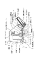
図4は、図3に示した記録装置の内部に備えられた変位手段および保持手段などについて説明するための図である。図4では、本体1の内部に被記録材が給送されていない状態が示されている。図5は、図3および図4に示したキャリッジ摺動軸20の一方の端部に取り付けられたカムについて説明するための図である。
【0062】
図4に示すように、キャリッジ摺動軸20の一方の端部は、図3に示した筐体1bの一方の側壁に形成された長穴48に挿入されてその長穴により支持され、キャリッジ摺動軸20他方の端部は、筐体1bの他方の側壁に形成された長穴に挿入されてその長穴により支持されている。キャリッジ摺動軸20の端部を支持するそれぞれの長穴は、それぞれの長穴の長手方向が主走査方向および副走査方向に対して垂直となるように筐体1bの側壁に形成されている。筐体1bに形成されたそれらの長穴によって、キャリッジ摺動軸20が上下方向、すなわち本体1内に搬送された被記録材11に対して垂直な方向に移動可能に、かつ、キャリッジ摺動軸20の中心軸を中心にキャリッジ摺動軸20が回動可能となるようにキャリッジ摺動軸20が支持されている。すなわち、キャリッジ摺動軸20の中心軸を中心に回動可能、かつ、被記録材11に対してほぼ垂直な方向に移動可能にキャリッジ摺動軸20を支持する手段が、キャリッジ摺動軸20の端部が挿入される長穴が形成された筐体1bの側壁によって構成されている。
【0063】
キャリッジ摺動軸20の、長穴48側と反対側の部分には、主走査方向および副走査方向に対してほぼ垂直な方向に延びるカムレバー46の下部が、その下部に取り付けられた止めねじ46aによって固定されている。また、キャリッジ摺動軸20の長穴48側の部分には、図5に示すようにカム47が止めねじ47aによって固定されている。カム47の下面は、筐体1bの内壁における長穴48の長手方向に対して垂直な当接面1cと接している。
【0064】
カムレバー46の下部の形状は、その下部がカムの役割を有するように形成されており、その下部の形状は、カム47の下部の形状を投影したものとなっている。従って、キャリッジ摺動軸20の両端にはカムが取り付けられていることになる。カムレバー46の下面は、筐体1bの内壁における長穴48の長手方向に対して垂直な当接面1dと接している。カムレバー46、カム47およびキャリッジ摺動軸20が一体となってキャリッジ摺動軸20の中心軸を中心に回転することにより、筐体1bの長穴の内部でその長穴の長手方向にキャリッジ摺動軸20がスライドして、キャリッジ摺動軸20が主走査方向および副走査方向に対して垂直な方向、すなわち上下方向に移動する。
【0065】
カムレバー46およびカム47は、カムレバー46およびカム47をそれぞれ固定する止めねじを緩めることにより、キャリッジ摺動軸20への取付け角度が調整可能となっている。カムレバー46またはカム47の少なくともいずれか一方のキャリッジ摺動軸20への取付け角度を調整することにより、被記録材11に対するキャリッジ摺動軸20の平行度、すなわち、主走査方向に対するキャリッジ摺動軸20の平行度を調整することができる。
【0066】
また、本参考形態の記録装置においては、実施形態で用いた上ガイド7の代わりに、上ガイド支持軸8により回動可能に支持された上ガイド17が用いられている。上ガイド17には、実施形態と同様に、検知用の従動ローラ6aが従動ローラ6aの中心軸を中心に回動可能に取り付けられている。上ガイド17の、従動ローラ6aよりも下流側の部分は、板状の弾性体部分17dとなっている。上ガイド17の上ガイド支持軸8側の部分には、その部分から主走査方向および副走査方向に対してほぼ垂直な方向に上方に向かって延びる検知レバー17cが形成されている。検知レバー17cは、検知レバー17cが弾性体部分17d側に向かって上ガイド支持軸8を中心に回転するように圧縮ばね49によって付勢されている。これにより、従動ローラ6aが駆動ローラ3側に付勢されると共に、弾性体部分17dが下ガイド板2側に付勢されている。
【0067】
検知レバー17cの上部には連結アーム45の一端部が連結ピン44により回動可能に取り付けられている。連結アーム45の他端部にはピン45aが形成されており、ピン45aは、カムレバー46の上部に形成された長穴46dに挿入されている。長穴46dの長手方向は、駆動ローラ3と従動ローラ6aとの間を通る被記録材の搬送方向に対してほぼ平行となっており、長穴46dに挿入されたピン45aは、長穴46dの内部で回動可能、かつ長穴46dの長手方向にスライド可能となっている。カムレバー46は、検知レバー17cよりも被記録材11の搬送方向下流側に配置されている。このカムレバー46は、カムレバー46に一端が取り付けられた第3の付勢手段であるカムレバーばね46cによって被記録材の搬送方向下流側に向かう方向、すなわち検知レバー17c側と反対側となる一方の方向にキャリッジ摺動軸20の中心軸を中心に回転するように付勢されている。
【0068】
また、カムレバー46の上面には、その面から突出し、かつ、主走査方向に延びる歯として山形部が複数形成されており、それら複数の山形部から第4の噛み合い部46bが構成されている。第4の噛み合い部46bのそれぞれの山形部における検知レバー17c側と反対側の面は、駆動ローラ3と従動ローラ6aとの間を通る被記録材に対してほぼ垂直な垂直面となり、それぞれの山形部における検知レバー17c側の面は、駆動ローラ3と従動ローラ6aとの間を通る被記録材に対して傾斜した傾斜面となっている。
【0069】
このようなカムレバー46の上方には、位置記憶レバー41が配置されている。位置記憶レバー41における被記録材の搬送方向下流側の端部は、筐体1bに形成された回転軸41aに回動可能に取り付けられている。位置記憶レバー41は、第4の付勢手段であるレバー押しばね42によってカムレバー46側に向かう方向に回転軸41aを中心に回転するように付勢されている。この位置記憶レバー41の下面、すなわちカムレバー46側の面には、その面から突出し、かつ、主走査方向に延びる歯として山形部が複数形成されており、それら複数の山形部から第3の噛み合い部41bが構成されている。第3の噛み合い部41bのそれぞれの歯、第4の噛み合い部46bのそれぞれの歯と噛み合うものである。第3の噛み合い部41bのそれぞれの山形部における検知レバー17c側の面は、駆動ローラ3と従動ローラ6aとの間を通る被記録材に対してほぼ垂直な垂直面となり、それぞれの山形部における検知レバー17c側と反対側の面は、駆動ローラ3と従動ローラ6aとの間を通る被記録材に対して傾斜した傾斜面となっている。
【0070】
第3の噛み合い部41bおよび第4の噛み合い部46bのそれぞれの山形部は、カムレバー46およびキャリッジ摺動軸20がキャリッジ摺動軸20の中心軸を中心に、カムレバー46が検知レバー17c側と反対側に向かう方向となる一方の方向に回転する動作を規制するためのものである。第3の噛み合い部41bおよび第4の噛み合い部46bと、レバー押しばね42とから一方向ラッチ機構が構成されている。この一方向ラッチ機構では、前述したように位置記憶レバー41がカムレバー46側に付勢され、かつ、カムレバー46が検知レバー17cから離れる方向に付勢されていることにより、第3の噛み合い部41bと第4の噛み合い部46bの互いの垂直面同士が圧接し、第3の噛み合い部41bと第4の噛み合い部46bが噛み合った状態が保持されている。
【0071】
上記の一方向ラッチ機構で噛み合い部同士が噛み合っている状態では、カムレバー46およびキャリッジ摺動軸20が、図4の矢印Eで示される方向、すなわちカムレバー46が検知レバー17c側と反対側に向かう方向となる一方の方向に回転する動作が規制されている。また、その状態では、カムレバー46およびキャリッジ摺動軸20が、図4の矢印Fで示される方向、すなわちカムレバー46が検知レバー17c側に向かう方向となる他方の方向に回転する動作が可能となっている。第3の噛み合い部41bと第4の噛み合い部46bの噛み合い位置がどのような位置であっても、第3の噛み合い部41bと第4の噛み合い部46bが噛み合っている状態では位置記憶レバー41の位置が常に一定になるようにすることが好ましい。
【0072】
本参考形態の記録装置では、被記録材11の厚さを検出する検出手段が、従動ローラ6a、上ガイド17および圧縮ばね49などから構成されており、その検出手段は、従動ローラ6aの変位量から被記録材11の厚さを検出するものである。また、前記検出手段により検出された被記録材11の厚さの検出結果に基づいて記録ヘッド23の吐出口を被記録材に対してほぼ垂直な方向に変位させる変位手段が、上ガイド17に形成された検知レバー17c、連結アーム45、カムレバー46、キャリッジ摺動軸20、カム47およびキャリッジ22などの部材から構成されている。その変位手段は、被記録材11に対してほぼ垂直な方向にキャリッジ摺動軸20を移動させることで、記録ヘッド23の吐出口を被記録材11に対してほぼ垂直な方向に変位させるものである。
【0073】
さらに、上述したように第3の噛み合い部41bおよび第4の噛み合い部46bやレバー押しばね42から構成された一方向ラッチ機構と、レバー押しばね42とから保持手段が構成されている。このように構成された保持手段は、キャリッジ摺動軸20の中心軸を中心にキャリッジ摺動軸20が回転する動作を規制するものであり、この保持手段によって、上記の変位手段により記録ヘッド23の吐出口が変位した際にその吐出口から被記録材11までの距離が保持される。
【0074】
さらに、本体1の内部には、カムレバー46の位置を初期状態にするための解除手段であるリセット部材43が備えられている。リセット部材43は、図3に示したキャリッジ62が、被記録材11上を除く特定の位置に移動した際に、位置記憶レバー41をカムレバー46から離れる方向に回転させて第3の噛み合い部41bと第4の噛み合い部46bの噛み合いを解除して、一方向ラッチ機構によるカムレバー46およびキャリッジ摺動軸20の前記一方向への回転動作の規制を解除するものである。リセット部材43によって第3の噛み合い部41bと第4の噛み合い部46bの噛み合いを解除することにより、カムレバー46がカムレバーばね46cによって引っ張られて初期状態の位置にリセットされ、カムレバー46と共にそれぞれの構成部品が初期の状態に戻る。それぞれの構成部品が初期の状態にあり、駆動ローラ3に従動ローラ6aが当接しているときには、キャリッジ摺動軸20と当接面1cとが距離B1だけ離れている。
【0075】
図6および図7は、図1に示した本体1の内部に被記録材11が給送された際の記録装置の動作について説明するための図である。図6には、駆動ローラ3と従動ローラ6aとの間を被記録材11が通過している状態が示されており、図7には、駆動ローラ3と従動ローラ6aとの間を被記録材11が通過した直後の状態が示されている。
【0076】
図6に示すように、駆動ローラ3と従動ローラ6aとの間に被記録材11が進入すると、検知レバー17cが圧縮バネ49に対抗してカムレバー46側と反対側の方向に、すなわち図6において時計方向に上ガイド支持軸8を中心に回転する。検知レバー17cの回転に伴って連結ピン44により連結アーム45が被記録材11の搬送方向上流側に移動し、これにより、カムレバー46がピン45aによって検知レバー17c側に向かう方向に、すなわち図6において時計方向にキャリッジ摺動軸20の中心軸を中心に回転する。キャリッジ摺動軸20と共にカム47もキャリッジ摺動軸20の中心軸を中心に回転し、このカム47およびカムレバー46の回転によって、キャリッジ摺動軸20が、キャリッジ摺動軸20の両端を支持するそれぞれの長穴に沿って上方に移動する。このようにキャリッジ摺動軸20が上方に移動することにより、図4に示した状態におけるキャリッジ摺動軸20と当接面1cとの間の距離B1が、図6に示すように距離B2に増大することになる。この距離B1とB2との差は、被記録材11の厚さとほぼ同一としてもよいが、必ずしも同一としなくともよい。
【0077】
図7に示すように、駆動ローラ3と従動ローラ6aとの間を被記録材11が通過した後には、圧縮ばね49により検知レバー17cが押圧されて、上ガイド17および従動ローラ6aが駆動ローラ3側に向かう方向に上ガイド支持軸8を中心に回転し、従動ローラ6aが駆動ローラ3と当接する。それと同時に、連結アーム45が連結ピン44により押されて被記録材11の搬送方向下流側に移動する。
【0078】
ここで、ピン45aがカムレバー46の長穴46dの内部でスライドするが、第3の噛み合い部41bと第4の噛み合い部46bとが噛み合っていることにより、カムレバー46における被記録材11の搬送方向下流側への回転が規制されており、キャリッジ摺動軸20と当接面1cとの間の距離B2が依然として保持されている。従って、この状態では、被記録材11と同じ厚みを有する、被記録材11と異なる別の被記録材に対して、記録ヘッド23は適切な位置にあり、記録ヘッド23によって被記録材11の搬送方向下流側の最端部にまで記録することができる。また、上ガイド17の先端の弾性体部分17dと、下ガイド板2との間を被記録材11が通過するまで、被記録材11が弾性体部分17dによって押さえつけられ、最後まで被記録材11の安定性を保つことができる。
【0079】
記録ヘッド23によって被記録材に記録が行われる記録可能領域を被記録材11が通過したのち、図4に示したリセット部材43により、図7の矢印Jで示される方向に位置記憶レバー41を回転させることにより、カムレバー46およびキャリッジ摺動軸20などのそれぞれの構成部品の位置が、図4に示した初期状態の位置に戻る。
【0080】
以上で説明したように本参考形態の記録装置においても、実施形態のものと同様に、被記録材11の厚さに応じて記録ヘッド23の吐出口が変位手段によって被記録材11に対して垂直な方向に変位されて吐出口と被記録材11との距離が被記録材11の厚さに対して適正な値に設定される。そして、その吐出口と被記録材11との距離が保持手段により保持された状態で、被記録材11に対して記録ヘッド23によって記録が行われる。従って、厚さが異なる複数の被記録材に対して記録を行う場合でも、被記録材の厚さに応じて記録ヘッド23の吐出口を変位させることで吐出口と被記録材との距離を常に適正な値に一定に保つことができ、記録ヘッド23によって被記録材に高精度の画像を記録することが可能となる。
【0081】
また、簡単な構成で、厚さの異なる複数の被記録材のそれぞれに対して記録ヘッド23の吐出口から被記録材までの距離を一定に保つことが可能となる。さらに、簡単な構造で、記録ヘッド23を検知結果に基づいて変位させて、その変位した位置を保持することができる。これにより、厚さが同一の複数の被記録材に記録を行う場合に、記録ヘッド23の吐出口を頻繁に変位させることなく、吐出口から被記録材までの距離を一定に保つことができるので、記録装置の低騒音および低エネルギーに対して効果的である。
【0082】
さらに、厚さの異なる被記録材に対して記録ヘッド23の吐出口から被記録材までの距離を一定に保つために、被記録材ではなく、吐出口を変位させることにより、被記録材は、厚みに関係なく一定の位置を通過するように搬送されるので、被記録材の搬送路の設計が容易になり、被記録材を安定して搬送することが可能となるという効果がある。
【0083】
(第2の参考形態)
図8は、本発明の第2の参考形態の記録装置について説明するための図である。本参考形態の記録装置では、第1の参考形態においてキャリッジを被記録材に対してほぼ垂直な方向に移動させるためにキャリッジ摺動軸を回転させる手段が、電子制御により駆動される回転駆動装置などから構成されている。よって、本参考形態の記録装置では、第1の参考形態のものと比較して、被記録材の厚さを検出する手段と、その検出手段によって検出された検出結果に基づいて記録ヘッドの吐出口を被記録材に対してほぼ垂直な変位させる変位手段と、その変位手段によって記録ヘッドの吐出口が変位した際にその吐出口から被記録材までの距離を保持する保持手段とが異なっている。以下では、第1の参考形態と異なる点を中心に説明する。
【0084】
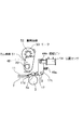
図8に示すように、本参考形態の記録装置では、キャリッジ摺動軸20の、長穴48側と反対側の部分に、第1の参考形態で用いたカムレバー46の代わりに、カム歯車51の下部が、その下部に取り付けられた止めねじ(不図示)によって固定されている。第1の参考形態で用いたカムレバー46と同様に、カム歯車51の下部の形状は、その下部がカムの役割を有するように形成されている。キャリッジ摺動軸20の、カムレバー46側と反対側の部分には、第1の参考形態の図5に示したカム47が第1の参考形態と同様に固定されており、カム歯車51の下部の形状が、カム47の下部の形状を投影したものとなっている。従って、キャリッジ摺動軸20の両端にカムが固定されている。
【0085】
カム歯車51の上面には、キャリッジ摺動軸20の中心軸を中心にカム歯車51を回転させるための複数の歯が形成されている。カム歯車51の上面に形成された歯には、回転駆動装置であるモータ53の回転軸の先端に取り付けられた駆動歯車52が噛み合わされている。
【0086】
一方、検知レバー17cの上部には、第1の参考形態で用いた連結アーム45の代わりに、位置センサー54が連結ピン44aによって取り付けられている。本参考形態の記録装置では、位置センサー54として差動トランスが用いられている。位置センサー54は、従動ローラ6aの変位量を、上ガイド17を介して検出してその変位量を電気信号に変換するものである。従動ローラ6a、上ガイド17、上ガイド17に形成された検知レバー17c、圧縮ばね49aおよび位置センサー54などから、被記録材11の厚さを検出する検出手段が構成されている。本参考形態のように検出手段として、従動ローラ6aや位置センサー54などから構成されたものを用いずに、超音波を用いて被記録材11の厚さを直接検出するものや、非接触型の厚さ検出装置を検出手段として用いてもよい。
【0087】
位置センサー54により変換された電気信号に基づいてモータ53を駆動することにより、モータ53の駆動力が駆動歯車52を介してカム歯車51に伝達され、被記録材11の厚さに応じてカム歯車51およびキャリッジ摺動軸20がキャリッジ摺動軸20の中心軸を中心に所定の角度だけ回転される。そして、キャリッジ摺動軸20の回転に伴って、カム歯車51およびカム47の作用によってキャリッジ摺動軸20およびキャリッジ62が被記録材11に対してほぼ垂直な方向に移動し、キャリッジ62に搭載されている記録ヘッド23の吐出口が被記録材11に対してほぼ垂直な方向に変位する。従って、モータ53、駆動歯車52、カム歯車51、キャリッジ摺動軸20、カム47およびキャリッジ62などから変位手段が構成されており、その変位手段によって、前記検出手段の検出結果に基づいて記録ヘッド23の吐出口が被記録材11に対してほぼ垂直な方向に変位させられる。
【0088】
また、モータ53は、カム歯車51およびキャリッジ摺動軸20の回転動作を規制することが可能なものである。従って、被記録材11の厚さに応じてモータ53の動作により記録ヘッド23の吐出口が変位した際にその吐出口から被記録材11までの距離を保持する保持手段としての機能を、上述したようにモータ53、駆動歯車52およびカム歯車51などから構成された変位手段が有している。
【0089】
図9は、本参考形態の記録装置に備えられた制御装置について説明するためのブロック図である。図9に示すように、本参考形態の記録装置に備えられた制御装置63は、演算装置61や記憶装置62などから構成されている。演算装置61は、位置センサー54により変換された電気信号を基に、記録ヘッド23の、被記録材11の厚さに対応する所定の位置を算出するものである。また、記憶装置62は、演算装置61により算出された前記所定の位置を位置データとして記憶するものである。
【0090】
この制御装置63によって、被記録材を搬送する動作、キャリッジ122が主走査方向に移動する動作、記録ヘッド123がインクを吐出する動作や、モータ53の動作などが制御される。また、本参考形態の記録装置には、記録ヘッド23の位置を検出する位置センサー53aが備えられており、位置センサー53aによって記録ヘッド23の位置を検出することで、記録ヘッド23の吐出口から被記録材11までの距離を検出することができる。
【0091】
このような記録装置では、駆動ローラ3と従動ローラ6aとの間に被記録材11が挟み込まれることにより、従動ローラ6aが駆動ローラ3から離れる方向に変位し、その従動ローラ6aの変位量が上ガイド17や連結アーム17cを介して位置センサー54に伝えられる。従動ローラ6aの変位量は位置センサー54によって検出され、その変位量が位置センサー54で電気信号に変換される。そして、従動ローラ6aの変位量は電気信号として位置センサー54から演算装置61に送られ、その従動ローラ6aの変位量に基づいて、記録ヘッド23の吐出口から被記録材11までの距離が適切な値になるような記録ヘッド23の位置が演算装置61によって算出される。演算装置61によって算出された演算結果は記憶装置62に記憶される。次に、記録ヘッド23の位置が、演算装置61による演算結果に対応した位置となるようにモータ53を駆動してキャリッジ摺動軸20を被記録材11に対して垂直な方向に移動させ、キャリッジ摺動軸20と共にキャリッジ22を移動させる。キャリッジ22と共に移動した記録ヘッド23の位置は位置センサー53aにより検出されてフィードバックされ、位置センサーb53aの検出結果と、記憶装置62に記憶されている記録ヘッド23の位置データとが一致するように制御装置63によって制御される。
【0092】
図10は、本参考形態の記録装置の制御動作について説明するためのタイムチャートである。図10(a)が、図9に示した位置センサー53aの出力信号のタイムチャートであり、図10(b)が、図8および図9に示した位置センサー54の出力信号のタイムチャートである。図10(a)および図10(b)に基づいて説明する制御動作では、位置センサー54と同時にモータ53の制御を開始し、駆動ローラ3と従動ローラ6aとの間を被記録材11が通過した時点から所定の時間が経過した後に記録ヘッド23の位置が初期状態の位置にリセットされる。従って、この制御動作では、駆動ローラ3と従動ローラ6aとの間に被記録材11が挟み込まれている際の、記録ヘッド23の吐出口から被記録材11までの距離が、駆動ローラ3と従動ローラ6aとの間を被記録材11が通過した後に所定の時間の間だけ保持されるように制御装置63によってモータ53などが制御される。
【0093】
図10(a)においては、記録ヘッド23が初期状態の位置にある時に位置センサー53aの出力が出力レベルAとなり、記録ヘッド23の吐出口が被記録材11に対して適切な位置に移動した際に位置センサー53aの出力が出力レベルBとなる。
【0094】
図10(b)に示すように、記録ヘッド23が初期状態の位置にあり、かつ、駆動ローラ3と従動ローラ6aが当接している状態から、時刻T1に駆動ローラ3と従動ローラ6aとの間に被記録材11の先端が挟み込まれると、位置センサー54の出力レベルが変化する。時刻T1の直後に、位置センサー54からの電気信号を基にモータ53が駆動されて記録ヘッド23が移動し、記録ヘッド23の移動に伴って、図10(a)に示すように位置センサー53aの出力は出力レベルAから出力レベルBへと変化する。
【0095】
その後、駆動ローラ3と従動ローラ6aとの間を被記録材11が通過し、時刻T2で従動ローラ6aが駆動ローラ3に当接する。そして、時刻T2から時間αだけ経過した時刻T3にリセットされて記録ヘッド23が初期状態の位置に戻り、位置センサー53aからの出力が出力レベルAとなる。
【0096】
上記の制御動作では、駆動ローラ3と従動ローラ6aとの間を被記録材が通過するごとに記録ヘッド23が初期状態の位置にリセットされるが、このような制御動作でなくともよく、例えば、図11に基づいて次に説明する制御動作を用いてもよい。
【0097】
図11は、本参考形態の記録装置の制御動作の変形例について説明するためのタイムチャートである。図11(a)が、図9に示した位置センサー53aの出力信号のタイムチャートであり、図11(b)が、図8および図9に示した位置センサー54の出力信号のタイムチャートである。図11(a)および図11(b)に基づいて説明する制御動作では、駆動ローラ3と従動ローラ6aとの間を被記録材11が通過した後に記録ヘッド23を初期状態の位置にリセットせず、被記録材11とは厚みが異なる別の被記録材が駆動ローラ3と従動ローラ6aとの間に挟み込まれた際にその別の被記録材の厚さに応じて記録ヘッド23が適切な位置に移動させられ、記録ヘッド23の吐出口の位置が更新される。すなわち、この制御動作では、2つめ以降の被記録材に記録を行う際に、その被記録材が駆動ローラ3と従動ローラ6aとの間に挟まれて検出されるまで、その前に記録された被記録材の厚さに対する記録ヘッド23の位置が記憶装置62に記憶されると共に、その記録ヘッド23の位置が保持されている。
【0098】
図11(a)においては、記録ヘッド23の吐出口が被記録材11に対して適切な位置に移動した際に、図10(a)と同様に位置センサー53aの出力が出力レベルBとなっている。また、図11(a)および図11(b)では、駆動ローラ3と従動ローラ6aとの間を被記録材11が通過した後の時間帯における位置センサーの出力が示されている。
【0099】
図11(a)に示すように駆動ローラ3と従動ローラ6aとの間を被記録材11が通過した後には、被記録材11と異なる別の被記録材が従動ローラ6aによって検出されるまで、被記録材11に記録を行っている時の記録ヘッド23の位置が保持され、位置センサー53aの出力が出力レベルBとなっている。図11(b)に示すように、被記録材11と異なる別の被記録材が時刻T11で駆動ローラ3と従動ローラ6aとの間に挟み込まれると、位置センサー54の出力レベルが変化する。ここで、位置センサー54から出力された電気信号により、記録ヘッド23の、その別の被記録材の厚さに対応する位置が演算装置61により算出され、算出された演算結果が記憶装置62に位置データとして記憶される。
【0100】
このように、別の被記録材の厚さに対する位置データが記憶装置62に記憶されることで、その前の時点で記憶装置62に記憶されていた位置データが更新される。そして、時刻T11から時間βだけ経過した時刻T12に、記憶装置62に記憶された位置データに対応する位置に記録ヘッド23が移動するようにその位置データを基にモータ53が駆動され、記録ヘッド23の移動に伴って、位置センサー53aの出力は出力レベルBから出力レベルCへと変化する。
【0101】
その後、駆動ローラ3と従動ローラ6aとの間を前記別の被記録材が通過し、時刻T13で従動ローラ6aが駆動ローラ3に当接することで、位置センサー54の出力レベルが元の値に戻る。
【0102】
図11に基づいて説明した制御動作では、被記録材に記録を行った後に、その被記録材と異なる別の被記録材が検出されるまで、記録ヘッド23の位置を保持すると共に記憶装置62に位置データが記憶されている。通常では、厚さがほぼ同一の複数の被記録材に記録を行う場合が多いので、このような制御動作では、記録ヘッド23の位置を初期状態の位置にリセットする回数や、記録ヘッド23を被記録材に対して垂直な方向に移動させる動作の回数が少なくなり、記録装置の耐久性および消音に対して効果的である。また、図11においては、時間βが0であってもよい。
【0103】
図10および図11のそれぞれで説明した制御動作は、本参考形態の記録装置だけでなく、実施形態および第1の参考形態の記録装置に適用することができる。実施形態および第1の参考形態のそれぞれの記録装置で図10の制御動作を適用する場合、時刻T1で被記録材11の厚さに応じて記録ヘッド23の位置をセットし、時刻T3で記録ヘッド23の位置をリセットする。また、実施形態および第1の参考形態のそれぞれの記録装置で図11の制御動作を適用する場合、時刻T12で、記録ヘッド23の位置をリセットする動作および、被記録材11と厚さが異なる別の被記録材の厚さに応じて記録ヘッド23の位置をセットする動作をこの順番で続けて行うとよい。
【0104】
以上で説明したように本参考形態の記録装置では、キャリッジ62を摺動可能に支持するキャリッジ摺動軸20が回転可能かつ、被記録材11に対して垂直な方向に移動可能に支持されると共にキャリッジ摺動軸20の両端にカムが取り付けられており、検出手段により被記録材の厚さを検出して得られた電気信号に基づいてモータ53によりキャリッジ摺動軸20を所定の角度だけ回転させることで、キャリッジ摺動軸20が回転する動作に伴ってキャリッジ摺動軸20の両端のカムにより被記録材11に対して略垂直な方向にキャリッジ摺動軸20が移動する。このように、キャリッジ摺動軸20や、キャリッジ摺動軸20により支持されるとともに記録ヘッド23を搭載したキャリッジ62を移動させて、被記録材11の厚さに応じて記録ヘッド23の吐出口と被記録材11との距離が適正な値となるように記録ヘッド23の吐出口を被記録材11に対して略垂直な方向に移動させる。そして、吐出口と被記録材11との距離が適正な値となるまでモータ53によりキャリッジ摺動軸20を回転させた後に、モータ53によりキャリッジ摺動軸20の回転動作を規制することで記録ヘッド23の吐出口から被記録材11までの距離を保持した状態で記録ヘッド23によって被記録材11に記録を行う。従って、厚さが異なる複数の被記録材に対して記録を行う場合でも、被記録材の厚さに応じて吐出口と被記録材との距離を常に適正な値に一定に保つことができ、被記録材に高精度の画像を記録することが可能となる。
【0105】
【発明の効果】
以上説明したように本発明は、以下のような効果がある。
【0106】
請求項1に記載の発明は、検出手段により検出された被記録材の厚さに応じて変位手段により記録手段の吐出口を被記録材に対してほぼ垂直な方向に変位させ、保持手段により吐出口から被記録材までの距離を保持することで、厚さが異なる複数の被記録材に対して記録を行う場合でも吐出口と被記録材との距離を常に適正な値に一定に保つことができ、記録手段によって被記録材に高精度の画像を記録することが可能となるという効果がある。
【0107】
また、被記録材を搬送するための駆動ローラ側に付勢された従動ローラの変位量から被記録材の厚さを検出し、その検出結果に基づいて、記録手段を搭載するための保持手段を、その保持手段を摺動可能に支持する摺動軸を中心に回転させたり、その検出結果に基づいて前記摺動軸を被記録材に対してほぼ垂直な方向に移動させたりする構成にすることで、簡単な構成で、厚さの異なる複数の被記録材のそれぞれに対して記録手段の吐出口から被記録材までの距離を一定に保つことが可能となるという効果がある。
【0108】
さらに、記録装置が上記のように構成されている場合、保持手段が、摺動軸を中心に保持部材が回転する動作を規制するものや、被記録材に対してほぼ垂直な方向に保持部材が移動する動作を規制するものであることにより、簡単な構造で、記録手段の吐出口が変位した位置に保持することができるという効果がある。その上、厚さが同一の複数の被記録材に記録を行う場合に、記録手段の吐出口を頻繁に変位させることなく、吐出口から被記録材までの距離を一定に保つことができるので、記録装置の低騒音および低エネルギーに対して効果的である。
【0109】
さらに、厚さの異なる被記録材に対して記録手段の吐出口から被記録材までの距離を一定に保つために、被記録材ではなく、吐出口を変位させることにより、被記録材は厚みに関係なく一定の位置を通過するように搬送されるので、被記録材の搬送路の設計が容易になり、被記録材を安定して搬送することが可能となるという効果がある。
【0110】
さらに、被記録材の厚さに基づいて記録手段の吐出口を変位させる構成が簡単であるので、被記録材の搬送制御も容易に行うことができるという効果がある。
【図面の簡単な説明】
【図1】 本発明の実施形態の記録装置を模式的に示す断面図である。
【図2】図1に示した記録装置の内部の構成について説明するための斜視図である。
【図3】 本発明の第1の参考形態の記録装置を模式的に示す断面図である
。
【図4】図3に示した記録装置の内部に備えられた変位手段および保持手段などについて説明するための図である。
【図5】図3および図4に示したキャリッジ摺動軸の一方の端部に取り付けられたカムについて説明するための図である。
【図6】図1に示した本体の内部に被記録材が給送された際の記録装置の動作について説明するための図である。
【図7】図1に示した本体の内部に被記録材が給送された際の記録装置の動作について説明するための図である。
【図8】 本発明の第2の参考形態の記録装置について説明するための図で
ある。
【図9】図8に基づいて説明した記録装置に備えられた制御装置について説明するためのブロック図である。
【図10】図8に基づいて説明した記録装置の制御動作について説明するためのタイムチャートである。
【図11】図8に基づいて説明した記録装置の制御動作の変形例について説明するためのタイムチャートである。
【図12】従来の記録装置を模式的に示す断面図である。
【図13】図12に示した記録装置の本体内のキャリッジの構成を説明するための斜視図である。
【符号の説明】
1 本体
1b 筐体
1c、1d 当接面
2 下ガイド板
3 駆動ローラ
4 排出駆動ローラ
5 拍車ローラ
6、6a 従動ローラ
7、17 上ガイド
7a セット溝
7b、17c 検知レバー
8 上ガイド支持軸
9 押さえばね
10、11 被記録材
12 自動給紙トレー
13 トレー加圧ばね
14 回転軸
15 Dカットローラ
17d 弾性体部分
20 キャリッジ摺動軸
21、21a 位置決めレール
22、62 キャリッジ
22a レバー
22b、41a 回転軸
22c スライドピン
23 記録ヘッド
31、41 位置記録レバー
31a 突起部
31b 第2の噛み合い部
32b 第1の噛み合い部
32 摺動部材
32a キャリッジ支持部
32c、46d 長穴
41b 第3の噛み合い部
42 レバー押しばね
43 リセット部材
44、44a 連結ピン
45 連結アーム
45a ピン
46 カムレバー
46a、47a 止めねじ
46b 第4の噛み合い部
46c カムレバーばね
47 カム
48 長穴
49、49a 圧縮ばね
51 カム歯車
52 駆動歯車
53 モータ
53a、54 位置センサー
61 演算装置
62 記憶装置
63 制御装置[0001]
BACKGROUND OF THE INVENTION
The present invention relates to an ink jet recording apparatus that performs recording on a recording material by discharging ink from the recording head to the recording material.
[0002]
[Prior art]
Recording devices that have functions such as printers, copiers, facsimiles, etc., or recording devices that are used as output devices for multifunction devices and workstations including computers and word processors, are based on image information. Etc.) is recorded on a recording material (recording medium) such as an image including characters and symbols. Such a recording apparatus can be classified into an ink jet type, a wire dot type, a thermal type, a thermal transfer type, a laser beam type, etc., depending on the recording method of the recording means used.
[0003]
In a serial type recording apparatus that employs a recording method in which main scanning is performed in a direction crossing the conveyance direction (sub-scanning direction) of the recording material, the recording material is set at a predetermined recording position, and then along the recording material. Then, an image including characters and symbols is recorded on the recording material by a recording head as recording means mounted on a carriage as a holding member that moves (main scan). After the recording of one line on the recording material is completed, the recording material is fed by a predetermined amount (sub-scanning), and then the image of the next line is recorded to repeat the recording operation. An image is recorded in the desired area of the material.
[0004]
On the other hand, in a line-type recording apparatus that records an image only by sub-scanning in which the recording material is fed in the transport direction, the recording material is set at a predetermined recording position, and recording for one line is continuously performed all at once. By performing a predetermined amount of paper feeding (pitch feeding) each time, an image is recorded on the entire recording material.
[0005]
Among the recording methods of the recording means described above, the ink jet type performs recording by ejecting ink from a recording head as a recording means to a recording material, and the recording head can be easily made compact. In addition, an ink jet recording apparatus that employs an ink jet method can record high-definition images at high speed, and can record ordinary paper without special processing. In addition, the running cost is low, the non-impact method is low in noise, and it is easy to record a color image using multicolor inks.
[0006]
An ink jet recording head is provided with an ejection port for ejecting a liquid such as ink, and recording is performed on the recording material by ejecting ink from the ejection port toward the recording material. As described above, in an ink jet recording apparatus that performs recording by ejecting ink droplets from a recording head to a recording paper that is a recording material, it is important to make the distance from the ejection port of the recording head to the recording paper constant. It is preferable to record by ejecting ink droplets from the ejection port at a relatively short distance from the recording paper. This is because, as the distance from the ejection port of the recording head to the recording sheet increases, an error occurs in the variation in the ink ejection direction, resulting in variations in the image recording position on the recording sheet.
[0007]
FIG. 12 is a cross-sectional view schematically showing a conventional recording apparatus. As shown in FIG. 12, in the main body 101 of the conventional recording apparatus, one end portion of the automatic paper feed tray 112 is attached to one end portion of the casing 101b by a rotating shaft 114. The automatic paper feed tray 112 is supported by the rotary shaft 114 so as to be rotatable about the rotary shaft 114. The other end of the automatic paper feed tray 112 is urged upward by a tray pressurizing spring 113, and the upper surface of the automatic paper feed tray 112 is covered with a sheet-like object fed into the main body 101. A plurality of recording materials 110 are stacked.
[0008]
Above the automatic paper feed tray 112, a D-cut roller 115 supported so as to be rotatable in one direction is provided. The shape of the D-cut roller 115 is a cylindrical one cut so that a part of the side surface of the cylinder is a plane parallel to the central axis of the cylinder. The D-cut roller 115 of the D-cut roller 115 The cross-sectional shape in the direction perpendicular to the central axis of the is a D-shape. The D-cut roller 115 is for automatically feeding the recording material 110 on the automatic paper feed tray 112 one by one toward the recording area in the main body 101. The D-cut roller 115 is rotated once in the direction indicated by the arrow B when necessary by a one-rotation clutch (not shown) provided in the housing 101b, and is automatically supplied along with the rotation of the D-cut roller 115. The uppermost recording material 110 on the paper tray 112 is conveyed into the main body 101 toward a driving roller 103 described later. FIG. 12 shows a state in which the recording material 111 in the uppermost layer among a plurality of recording materials 110 on the automatic paper feed tray 112 is fed into the main body 101.
[0009]
On the downstream side in the conveyance direction of the recording material conveyed from the automatic paper feed tray 112 by the D cut roller 115, an upper guide 107 whose one end is rotatably supported by the upper guide support shaft 108, and the D cut roller 115 A driving roller 103 that is rotated to convey the recording material 111 conveyed in the sub-scanning direction, and a driven roller 106 that is attached to the upper guide 107 so as to be disposed above the driving roller 103. Yes. The upper guide 107 is disposed on the upper side of the conveyance path of the recording material 111, and an upper end of the upper guide 107 on the upstream side in the conveyance direction of the recording material 111 is supported by the upper guide support shaft 108. Further, the upper guide 107 is urged downward by the presser spring 109, that is, the upper guide 107 is rotated counterclockwise around the upper guide support shaft 108 in FIG. A driven roller 106 is attached to the substantially central portion of the upper guide 107 so as to be rotatable about the central axis of the driven roller 106. Therefore, the driven roller 106 is urged in the direction toward the driving roller 103 so as to be in pressure contact with the driving roller 103 by the urging force of the pressing spring 109 to the upper guide 107.
[0010]
The driven roller 106 can rotate around the upper guide support shaft 108 together with the upper guide 107, that is, the driven roller 106 can swing, and the driven roller 106 is displaced in a direction away from the driving roller 103. A recording material 111 is sandwiched between the driven roller 106 and the driving roller 103. The recording material 111 is sandwiched between the driven roller 106 and the driving roller 103 while the driving roller 103 rotates in the direction of arrow D, so that a conveying force is applied to the recording material 111. When nothing is sandwiched between the driving roller 103 and the driven roller 106, the driven roller 106 is in pressure contact with the driving roller 103 by the urging force of the pressing spring 109.
[0011]
In addition, a
[0012]
On the downstream side of the drive roller 103 in the conveyance path of the recording material 111, a lower guide plate 102 that defines the conveyance path of the recording material 111 is fixed. A part of the upper surface of the lower guide plate 102 faces the ejection port surface of the
[0013]
Further, on the downstream side of the
[0014]
In the conventional recording apparatus configured as described above, the uppermost recording material 110 among the plurality of recording materials 110 on the automatic paper feeding tray 112 is appropriately rotated by the automatic rotation of the D-cut roller 115 once. To the driving roller 103. The recording material 111 fed to the driving roller 103 is transported along the lower guide plate 102 so as to pass under the
[0015]
FIG. 13 is a perspective view for explaining the configuration of the
[0016]
[Problems to be solved by the invention]
However, in the conventional inkjet recording apparatus, when recording is performed on recording sheets having different thicknesses, the distance from the ejection port of the recording head to the recording sheet differs for each recording sheet depending on the thickness of the recording sheet. There is a problem that the quality of the image recorded on the paper is impaired. Further, when recording on a thick recording material, when the thick recording material passes through the recording portion where recording is performed by the recording head, due to the difference in thickness of the recording material, the recording head discharge port Even the recording material contacted.
[0017]
In addition, in order to prevent a reduction in image quality due to different thicknesses of a plurality of recording papers, an attempt has been made to configure a recording material conveyance path based on the recording side surface of the recording material. However, when the recording material is thin paper, the distance between the recording material and the recording head could not be kept constant, and the distance from the ejection port to the recording paper could not be kept constant. . Therefore, the conventional inkjet recording apparatus does not have any means for solving these problems, and the distance from the ejection port of the recording head to the recording material can be further stabilized even when the thickness of the recording material is different. It was difficult.
[0018]
For this reason, even if the recording head is moved in the main scanning direction and the recording material is transported in the sub-scanning direction with high accuracy, variations in the direction in which the ink droplets are ejected correspond to changes in the distance that the ink droplets travel. As a result, the landing point of the ink varies and the high definition of the image is impaired.
[0019]
The object of the present invention is to provide a plurality of different thicknesses.seedEven when recording on other recording materials, the distance from the ejection port of the recording head to the recording material is kept constant without depending on the thickness of the recording material. An object of the present invention is to provide a recording apparatus capable of recording.
[0020]
[Means for Solving the Problems]
In order to achieve the above-described object, the present invention provides a recording in which an ejection port for ejecting liquid is formed, and recording is performed on the recording material by ejecting liquid from the ejection port toward a sheet-like recording material. Holding member for mounting meansAnd a slide shaft that slidably supports the holding member so as to be able to reciprocate on a straight line, and the recording material so that the recording material passes through the vicinity of the discharge port of the recording means. A drive roller that rotates to conveyIn a recording apparatus havingThe recording material is urged toward the driving roller so as to come into pressure contact with the driving roller and displaced in a direction away from the driving roller, and the recording material is sandwiched between the driving roller and a conveying force is applied to the recording material. A follower roller, and is disposed on one end side of the sliding shaft, and from the displacement amount of the follower rollerA detecting means for detecting the thickness of the recording material; and the discharge port of the recording means is substantially omitted from the recording material based on a detection result of the thickness of the recording material detected by the detecting means. Displacement means for displacing in a vertical direction, and holding means for holding a distance from the discharge port to the recording material when the discharge port of the recording unit is displaced by the displacement unit.Prepare. The displacement means engages with the engagement groove that is displaced according to the displacement amount of the driven roller and the engagement groove when the holding member moves in a direction approaching the detection means. And an engaging projection for displacing the outlet. Further, the holding means is movable integrally with the holding member, and the holding member moves in a direction away from the detecting means, so that the engaging protrusion no longer engages with the engaging groove. Even in the state, the distance from the discharge port to the recording material is maintained.
[0021]
In the above invention, the thickness of the sheet-like recording material recorded by the recording means mounted on the holding member is detected by the detection means, and the discharge port of the recording means is displaced based on the detection result. Is displaced in a direction substantially perpendicular to the recording material, and the distance from the ejection port to the recording material when the ejection port is displaced is held by the holding means. In this way, the discharge port is displaced by the displacing means according to the thickness of the recording material, and the distance between the discharge port and the recording material is set to an appropriate value with respect to the thickness of the recording material. In a state where the distance between the outlet and the recording material is held by the holding device, recording is performed by the recording device on the recording material whose thickness is detected by the detection device. Accordingly, even when recording is performed on a plurality of recording materials having different thicknesses, the distance between the ejection port and the recording material is always changed by displacing the ejection port of the recording unit according to the thickness of the recording material. It can be kept constant at an appropriate value, and a high-precision image can be recorded on the recording material by the recording means.
[0022]
Specifically, the recording apparatus is in pressure contact with the driving roller that rotates to convey the recording material so that the recording material passes through the vicinity of the discharge port of the recording unit. A driven roller that is urged toward the driving roller and is displaced in a direction away from the driving roller to sandwich the recording material with the driving roller to give a conveyance force to the recording material; And the detecting means detects the thickness of the recording material from the amount of displacement of the driven roller. In this case, a plurality of the driven rollers urged toward the drive roller so as to come into pressure contact with the drive roller are arranged in parallel in a direction perpendicular to the conveyance direction of the recording material, and the detection means Among the plurality of driven rollers, the thickness of the recording material is detected from the amount of displacement of the driven roller close to the side serving as a conveyance reference in the recording material.
[0023]
As described above, the detection means for detecting the thickness of the recording material detects the thickness from the displacement amount of the driven roller biased toward the driving roller for conveying the recording material. Thus, detection means capable of detecting the thickness of the recording material with a simple configuration can be obtained. Further, the detection means detects the thickness of the recording material from the amount of displacement of the driven roller close to the side serving as a conveyance reference in the recording material among the plurality of driven rollers, so that the size differs. Also for the recording material, it is possible to obtain detection means capable of detecting the thickness of the recording material with a simple configuration.
[0024]
Also,in frontThe displacement means displaces the discharge port of the recording means in a direction substantially perpendicular to the recording material by rotating the holding member about the sliding shaft.Togapreferable.
[0028]
DETAILED DESCRIPTION OF THE INVENTION
Next, embodiments of the present invention will be described with reference to the drawings.
[0029]
(ActualFIG. 1 shows the present invention.The fruitIt is sectional drawing which shows typically the recording device of embodiment. As shown in FIG. 1, in the main body 1 of the recording apparatus of the present embodiment, one end of an automatic paper feed tray 12 is attached to one end of a housing 1b by a rotating shaft 14. The automatic paper feed tray 12 is supported by the rotary shaft 14 so as to be rotatable about the rotary shaft 14. The other end of the automatic paper feed tray 12 is urged upward by a tray pressurizing spring 13, and the upper surface of the automatic paper feed tray 12 is covered with a sheet-like cover fed into the main body 1. A plurality of recording materials 10 are laminated.
[0030]
Above the automatic paper feed tray 12, a D-cut roller 15 supported so as to be rotatable in one direction is provided. The shape of the D cut roller 15 is a cylindrical one cut so that a part of the side surface of the cylinder is a plane parallel to the central axis of the cylinder. The cross-sectional shape in the direction perpendicular to the central axis of the is a D-shape. The D-cut roller 15 is for automatically feeding the recording material 10 on the automatic paper feed tray 12 one by one toward the recording area in the main body 1. The D-cut roller 15 is rotated once in the direction indicated by the arrow B by a one-rotation clutch (not shown) provided in the housing 1b when necessary, and is automatically supplied as the D-cut roller 15 rotates. The uppermost recording material 10 on the paper tray 12 is conveyed to the inside of the main body 1 toward a driving
[0031]
On the downstream side in the conveyance direction of the recording material conveyed from the automatic paper feed tray 12 by the D cut roller 15, an
[0032]
The driven roller 6 can rotate around the upper
[0033]
In addition, a
[0034]
A
[0035]
On the downstream side of the driving
[0036]
Further, on the downstream side of the
[0037]
In the recording apparatus of this embodiment configured as described above, the uppermost recording material among the plurality of recording materials 10 on the automatic paper feeding tray 12 is automatically fed by one rotation of the D-cut roller 15 as appropriate. The paper is fed from the tray 12 to the driving
[0038]
FIG. 2 is a perspective view for explaining the internal configuration of the recording apparatus shown in FIG. As shown in FIGS. 1 and 2, the sliding member 32 for supporting the
[0039]
When the lower part of the
[0040]
A rotating shaft 22 b parallel to the positioning rail 21 is formed on the upper portion of the side wall of the
[0041]
On the upper surface of the sliding member 32, a plurality of chevron portions are formed as teeth that protrude from the surface and extend in the main scanning direction, and a first meshing portion 32b is constituted by the plurality of chevron portions. The surface on the opposite side to the
[0042]
On the other hand, on the lower surface of the position storage lever 31, that is, the surface on the sliding member 32 side, as a tooth that meshes with each tooth of the first meshing portion 32b, a chevron that protrudes from the surface and extends in the main scanning direction. A plurality of portions are formed, and the second engaging portion 31b is constituted by the plurality of mountain-shaped portions. The surface on the rotating shaft 22b side in each chevron of the second meshing portion 31b is a vertical surface substantially perpendicular to the
[0043]
The respective chevron portions of the first meshing portion 32b and the second meshing portion 31b are such that the
[0044]
Here, as described above, the position storage lever 31 is urged toward the sliding member 32 by the second urging means, and the
[0045]
When the position storage lever 31 is rotated about the rotation shaft 22b in the direction away from the sliding member 32 from the state where the first engagement portion 32b and the second engagement portion 31b are engaged, the engagement portion of the positioning recording lever 31 31b is disengaged from the first meshing portion 32b. Accordingly, the
[0046]
The operation of setting the position of the
[0047]
Further, as shown in FIG. 2, the
[0048]
Next, detection means for detecting the thickness of the recording material and displacement means for displacing the ejection port of the
[0049]
In FIG. 1, a plurality of driven rollers 6 attached to the
[0050]
As shown in FIG. 2, the
[0051]
In the recording apparatus of the present embodiment, the detection means for detecting the thickness of the
[0052]
Further, as described above, the one-way latch constituted by the first engagement portion 32b and the second engagement portion 31b and the second urging means for urging the position storage lever 31 toward the sliding member 32 side. The holding means is composed of the mechanism and the first urging means for urging the
[0053]
In the recording apparatus configured as described above, when the
[0054]
When the
[0055]
Thereafter, even if the
[0056]
As described above, in the recording apparatus according to the present embodiment, the detection result is obtained by detecting the thickness of the sheet-
[0057]
In addition, with a simple configuration, it is possible to keep the distance from the ejection port of the
[0058]
Furthermore, in order to keep the distance from the ejection port of the
[0059]
(No.1ofreferenceForm) FIG. 3 shows the configuration of the present invention.1ofreferenceIt is sectional drawing which shows the recording device of a form typically. BookreferenceIn the recording device of the form, RealCompared to the embodiment, a displacement means for displacing the ejection port of the recording head in a direction substantially perpendicular to the recording material, and when the ejection port of the recording head is displaced by the displacement means, The holding means for holding the distance from the recording material is mainly different.. FruitIn the recording apparatus of the embodiment, since the carriage is rotated around the carriage slide shaft in order to adjust the distance from the ejection port of the recording head to the surface of the recording material, the thickness of the recording material changes greatly. Can not respond. In contrast, the bookreferenceIn the recording apparatus of the embodiment, since the carriage sliding shaft that slidably supports the carriage is moved in a direction substantially perpendicular to the surface of the recording material, the ejection port of the recording head is displaced., RealAs in the embodiment, the error in the recording position of the recording image due to the rotation angle of the recording head is eliminated. In FIG., RealThe same reference numerals are given to the same components as the embodiment, and in the following,, RealThe description will focus on the differences from the embodiment.
[0060]
BookreferenceIn the recording apparatus of the embodiment, as shown in FIG. 3, a
[0061]
FIG. 4 is a diagram for explaining a displacement unit, a holding unit, and the like provided in the recording apparatus illustrated in FIG. FIG. 4 shows a state where the recording material is not fed into the main body 1. FIG. 5 is a view for explaining a cam attached to one end of the
[0062]
As shown in FIG. 4, one end of the
[0063]
A lower portion of a
[0064]
The shape of the lower portion of the
[0065]
The mounting angle of the
[0066]
Also bookreferenceIn the recording device of the form, RealInstead of the
[0067]
One end of a connecting
[0068]
Further, a plurality of chevron portions are formed on the upper surface of the
[0069]
A
[0070]
The chevron portions of the
[0071]
In a state where the meshing portions are engaged with each other by the one-way latch mechanism, the
[0072]
In the recording apparatus according to the present embodiment, the detecting means for detecting the thickness of the
[0073]
Further, as described above, the one-way latch mechanism constituted by the third
[0074]
Further, inside the main body 1, a reset member 43 is provided as release means for setting the position of the
[0075]
6 and 7 are diagrams for explaining the operation of the recording apparatus when the
[0076]
As shown in FIG. 6, when the
[0077]
As shown in FIG. 7, after the
[0078]
Here, the
[0079]
After the
[0080]
Book as explained abovereferenceIn the recording device of the form, RealSimilar to the embodiment, the ejection port of the
[0081]
In addition, with a simple configuration, it is possible to keep the distance from the ejection port of the
[0082]
Furthermore, in order to keep the distance from the ejection port of the
[0083]
(No.2ofreferenceForm)
FIG. 8 shows the first aspect of the present invention.2ofreferenceIt is a figure for demonstrating the recording device of form. BookreferenceIn the recording device of the form,1ofreferenceIn the embodiment, the means for rotating the carriage slide shaft in order to move the carriage in a direction substantially perpendicular to the recording material is constituted by a rotary drive device driven by electronic control. So bookreferenceIn the recording device of the form,1ofreferenceA means for detecting the thickness of the recording material, and a displacement for displacing the ejection head of the recording head substantially perpendicularly to the recording material based on the detection result detected by the detection means, as compared with the configuration And the holding means for holding the distance from the ejection port to the recording material when the ejection port of the recording head is displaced by the displacement unit. In the following,1ofreferenceThe description will focus on the differences from the form.
[0084]
As shown in FIG.referenceIn the recording apparatus according to the embodiment, the
[0085]
On the upper surface of the cam gear 51, a plurality of teeth for rotating the cam gear 51 around the central axis of the
[0086]
On the other hand, the upper part of the detection lever 17c1ofreferenceInstead of the connecting
[0087]
By driving the
[0088]
Further, the
[0089]
Figure 9 shows the bookreferenceIt is a block diagram for demonstrating the control apparatus with which the recording apparatus of the form was equipped. As shown in FIG.referenceThe control device 63 provided in the recording apparatus includes an
[0090]
The controller 63 controls the operation of conveying the recording material, the operation of moving the
[0091]
In such a recording apparatus, when the
[0092]
Figure 10 shows the bookreference6 is a time chart for explaining a control operation of the recording apparatus of the embodiment. FIG. 10A is a time chart of the output signal of the position sensor 53a shown in FIG. 9, and FIG. 10B is a time chart of the output signal of the
[0093]
10A, when the
[0094]
As shown in FIG. 10B, from the state where the
[0095]
Thereafter, the
[0096]
In the above control operation, the
[0097]
Figure 11 shows the bookreference10 is a time chart for explaining a modification of the control operation of the recording apparatus of the embodiment. 11A is a time chart of the output signal of the position sensor 53a shown in FIG. 9, and FIG. 11B is a time chart of the output signal of the
[0098]
In FIG. 11A, when the ejection port of the
[0099]
As shown in FIG. 11A, after the
[0100]
As described above, the position data with respect to the thickness of another recording material is stored in the
[0101]
Thereafter, the other recording material passes between the driving
[0102]
In the control operation described with reference to FIG. 11, after recording on the recording material, the position of the
[0103]
The control operations described in FIG. 10 and FIG.referenceNot only in the form of recording device,EmbodimentAnd second1ofreferenceThe present invention can be applied to a recording apparatus of a form.EmbodimentAnd second1ofreferenceWhen the control operation of FIG. 10 is applied to each recording apparatus of the embodiment, the position of the
[0104]
Book as explained abovereferenceIn the recording apparatus according to the embodiment, the
[0105]
【The invention's effect】
As described above, the present invention has the following effects.
[0106]
According to the first aspect of the present invention, the discharge port of the recording unit is displaced in a direction substantially perpendicular to the recording material by the displacement unit according to the thickness of the recording material detected by the detection unit, and the holding unit is used. By maintaining the distance from the discharge port to the recording material, the distance between the discharge port and the recording material is always kept at an appropriate value even when recording is performed on a plurality of recording materials having different thicknesses. Therefore, it is possible to record a highly accurate image on the recording material by the recording unit.
[0107]
Further, the holding means for detecting the thickness of the recording material from the displacement amount of the driven roller biased to the driving roller side for conveying the recording material and mounting the recording means based on the detection result Is configured to rotate about a slide shaft that slidably supports the holding means, or to move the slide shaft in a direction substantially perpendicular to the recording material based on the detection result. By doing so, there is an effect that the distance from the ejection port of the recording means to the recording material can be kept constant with respect to each of the plurality of recording materials having different thicknesses with a simple configuration.
[0108]
Further, when the recording apparatus is configured as described above, the holding means regulates the movement of the holding member about the sliding shaft, or the holding member in a direction substantially perpendicular to the recording material. By restricting the movement of the recording medium, there is an effect that the discharge port of the recording means can be held at the displaced position with a simple structure. In addition, when recording on a plurality of recording materials having the same thickness, the distance from the ejection port to the recording material can be kept constant without frequently displacing the ejection port of the recording means. It is effective for the low noise and low energy of the recording apparatus.
[0109]
Furthermore, in order to keep the distance from the recording medium ejection port to the recording material constant with respect to the recording material having different thicknesses, the recording material is made thicker by displacing the ejection port instead of the recording material. Therefore, it is easy to design the recording material conveyance path, and it is possible to stably convey the recording material.
[0110]
Furthermore, since the configuration for displacing the ejection port of the recording means based on the thickness of the recording material is simple, there is an effect that the conveyance control of the recording material can be easily performed.
[Brief description of the drawings]
FIG. 1 shows the present invention.The fruitIt is sectional drawing which shows typically the recording device of embodiment.
FIG. 2 is a perspective view for explaining an internal configuration of the recording apparatus shown in FIG.
FIG. 3 shows the first aspect of the present invention.1ofreferenceFIG. 2 is a cross-sectional view schematically showing a recording apparatus according to an embodiment
.
4 is a diagram for explaining a displacement unit, a holding unit, and the like provided in the recording apparatus illustrated in FIG. 3; FIG.
5 is a view for explaining a cam attached to one end of a carriage slide shaft shown in FIGS. 3 and 4. FIG.
6 is a diagram for explaining the operation of the recording apparatus when a recording material is fed into the main body shown in FIG. 1; FIG.
7 is a diagram for explaining the operation of the recording apparatus when a recording material is fed into the main body shown in FIG. 1; FIG.
FIG. 8 shows the first of the present invention.2ofreferenceIt is a figure for demonstrating the recording device of form
is there.
FIG. 9 is a block diagram for explaining a control device provided in the recording apparatus described with reference to FIG. 8;
FIG. 10 is a time chart for explaining a control operation of the recording apparatus described with reference to FIG.
FIG. 11 is a time chart for explaining a modification of the control operation of the recording apparatus described based on FIG. 8;
FIG. 12 is a cross-sectional view schematically showing a conventional recording apparatus.
13 is a perspective view for explaining a configuration of a carriage in the main body of the recording apparatus shown in FIG. 12. FIG.
[Explanation of symbols]
1 Body
1b housing
1c, 1d Contact surface
2 Lower guide plate
3 Driving roller
4 Discharge drive roller
5 Spur Roller
6, 6a Follower roller
7, 17 Upper guide
7a Set groove
7b, 17c Detection lever
8 Upper guide support shaft
9 Presser spring
10, 11 Recording material
12 Automatic paper feed tray
13 Tray pressurizing spring
14 Rotating shaft
15 D cut roller
17d Elastic part
20 Carriage sliding shaft
21, 21a Positioning rail
22, 62 Carriage
22a lever
22b, 41a Rotating shaft
22c Slide pin
23 Recording head
31, 41 Position recording lever
31a Protrusion
31b 2nd meshing part
32b 1st meshing part
32 Sliding member
32a Carriage support
32c, 46d slot
41b Third meshing portion
42 Lever push spring
43 Reset member
44, 44a Connecting pin
45 Linking arm
45a pin
46 Cam lever
46a, 47a Set screw
46b 4th meshing part
46c cam lever spring
47 Cam
48 long hole
49, 49a Compression spring
51 Cam gear
52 Drive gear
53 Motor
53a, 54 Position sensor
61 Arithmetic unit
62 Storage device
63 Control device
Claims (5)
前記駆動ローラと圧接するように前記駆動ローラ側に付勢され前記駆動ローラから離れる方向に変位して前記駆動ローラとの間に前記被記録材を挟み込むことで前記被記録材に搬送力を与えるための従動ローラを有し、前記摺動軸の一端側に配され前記従動ローラの変位量から前記被記録材の厚さを検出する検出手段と、
前記検出手段により検出された前記被記録材の厚さの検出結果に基づいて前記記録手段の前記吐出口を前記被記録材に対して略垂直な方向に変位させる変位手段と、
前記変位手段により前記記録手段の前記吐出口が変位した際に前記吐出口から前記被記録材までの距離を保持する保持手段とを備え、
前記変位手段は、前記従動ローラの変位量に応じて変位する係合溝と、前記保持部材が前記検出手段に近づく方向に移動したときに前記係合溝に係合することによって前記吐出口を変位させる係合突部とを有し、
前記保持手段は、前記保持部材と一体的に移動可能であり、前記保持部材が前記検出手段から離れる方向に移動して、前記係合突部が前記係合溝と係合しなくなった状態でも前記吐出口から前記被記録材までの距離を保持することを特徴とする記録装置。A holding member for mounting recording means for forming recording on the recording material by ejecting liquid from the ejection port toward the sheet-like recording material ; For transporting the recording material so that the recording material passes through a slide shaft that slidably supports the holding member so as to be reciprocally movable, and in the vicinity of the discharge port of the recording means. In a recording apparatus having a driving roller that rotates ,
The recording material is urged toward the driving roller so as to come into pressure contact with the driving roller and displaced in a direction away from the driving roller, and the recording material is sandwiched between the driving roller and a conveying force is applied to the recording material. Detecting means for detecting the thickness of the recording material from the amount of displacement of the driven roller disposed on one end side of the sliding shaft .
Displacement means for displacing the ejection port of the recording means in a direction substantially perpendicular to the recording material based on the detection result of the thickness of the recording material detected by the detection means;
Holding means for holding a distance from the discharge port to the recording material when the discharge port of the recording unit is displaced by the displacement unit ;
The displacing means engages with the engaging groove that is displaced according to the displacement amount of the driven roller, and the engaging groove when the holding member moves in a direction approaching the detecting means. An engaging projection to be displaced,
The holding means can move integrally with the holding member, and the holding member moves in a direction away from the detecting means, so that the engagement protrusion is not engaged with the engagement groove. A recording apparatus that maintains a distance from the ejection port to the recording material .
前記変位手段は、前記保持部材に支持された変位位置記憶部材と、前記支持部材に設けられた検知部材とを有し、前記係合溝が前記検知部材に設けられ、前記係合突部が前記変位位置記憶部材に設けられている請求項1に記載の記録装置。 The detection means includes a support member that rotatably supports the driven roller, and a support shaft that rotatably supports the support member.
The displacement means includes a displacement position storage member supported by the holding member and a detection member provided on the support member, the engagement groove is provided on the detection member, and the engagement protrusion is The recording apparatus according to claim 1, wherein the recording apparatus is provided on the displacement position storage member .
前記保持部材が前記摺動軸を中心に一方の方向に回転する動作を規制し、前記保持部材が前記摺動軸を中心に他方の方向に回転する動作が可能な一方向ラッチ機構とから前記保持手段が構成されている請求項1ないし4のいずれか1項に記載の記録装置。First urging means for urging the holding member so that the holding member rotates in one direction around the sliding shaft;
From the one-way latch mechanism that restricts the movement of the holding member in one direction around the sliding shaft, and the movement of the holding member in the other direction around the sliding shaft. recording apparatus according to any one of claims 1 holding means are constituted 4.
Priority Applications (1)
| Application Number | Priority Date | Filing Date | Title |
|---|---|---|---|
| JP37344998A JP3745146B2 (en) | 1998-12-28 | 1998-12-28 | Recording device |
Applications Claiming Priority (1)
| Application Number | Priority Date | Filing Date | Title |
|---|---|---|---|
| JP37344998A JP3745146B2 (en) | 1998-12-28 | 1998-12-28 | Recording device |
Publications (2)
| Publication Number | Publication Date |
|---|---|
| JP2000190474A JP2000190474A (en) | 2000-07-11 |
| JP3745146B2 true JP3745146B2 (en) | 2006-02-15 |
Family
ID=18502181
Family Applications (1)
| Application Number | Title | Priority Date | Filing Date |
|---|---|---|---|
| JP37344998A Expired - Fee Related JP3745146B2 (en) | 1998-12-28 | 1998-12-28 | Recording device |
Country Status (1)
| Country | Link |
|---|---|
| JP (1) | JP3745146B2 (en) |
Families Citing this family (2)
| Publication number | Priority date | Publication date | Assignee | Title |
|---|---|---|---|---|
| JP5022144B2 (en) | 2007-08-30 | 2012-09-12 | 株式会社リコー | Image transfer device, image fixing device, resist conveying device, image forming device |
| JP4888670B2 (en) * | 2009-08-03 | 2012-02-29 | セイコーエプソン株式会社 | Liquid ejector |
-
1998
- 1998-12-28 JP JP37344998A patent/JP3745146B2/en not_active Expired - Fee Related
Also Published As
| Publication number | Publication date |
|---|---|
| JP2000190474A (en) | 2000-07-11 |
Similar Documents
| Publication | Publication Date | Title |
|---|---|---|
| JP4265612B2 (en) | Image recording device | |
| US8205956B2 (en) | Image recording apparatus | |
| US8092004B2 (en) | Image recording apparatus | |
| US7775656B2 (en) | Image recording apparatus | |
| US7722182B2 (en) | Inkjet recording device and driving unit provided therein | |
| JP4285490B2 (en) | Image recording device | |
| JP2009051092A (en) | Inkjet recorder | |
| JP4764073B2 (en) | Sheet feeding apparatus and recording apparatus | |
| JP3595779B2 (en) | Recording device | |
| JP2009269725A (en) | Recording device | |
| US7083245B2 (en) | Recording apparatus | |
| JP6116525B2 (en) | Carriage device | |
| JP3745146B2 (en) | Recording device | |
| JPH10309842A (en) | Recording apparatus | |
| US8047534B2 (en) | Sheet accommodating device and image recording apparatus with a translating pressing member attached to a rotating tray cover | |
| JP4078241B2 (en) | Recording device | |
| JP2006212995A (en) | Processing gap adjustment mechanism, processing gap adjustment method and printing device | |
| JP4957004B2 (en) | Inkjet recording device | |
| JP7423339B2 (en) | Feeding device and recording device | |
| JP2006347119A (en) | Recorder | |
| JP3305146B2 (en) | Sheet material feeding device, recording device, and sheet material separating method | |
| JP6891407B2 (en) | Inkjet recording device | |
| JP3904071B2 (en) | Recording medium positioning device and recording device | |
| JP2007160592A (en) | Recorder | |
| JP2007119190A (en) | Recording device |
Legal Events
| Date | Code | Title | Description |
|---|---|---|---|
| A977 | Report on retrieval |
Free format text: JAPANESE INTERMEDIATE CODE: A971007 Effective date: 20041026 |
|
| A131 | Notification of reasons for refusal |
Free format text: JAPANESE INTERMEDIATE CODE: A131 Effective date: 20041201 |
|
| A521 | Written amendment |
Free format text: JAPANESE INTERMEDIATE CODE: A523 Effective date: 20050131 |
|
| RD03 | Notification of appointment of power of attorney |
Free format text: JAPANESE INTERMEDIATE CODE: A7423 Effective date: 20050131 |
|
| TRDD | Decision of grant or rejection written | ||
| A01 | Written decision to grant a patent or to grant a registration (utility model) |
Free format text: JAPANESE INTERMEDIATE CODE: A01 Effective date: 20051109 |
|
| A61 | First payment of annual fees (during grant procedure) |
Free format text: JAPANESE INTERMEDIATE CODE: A61 Effective date: 20051116 |
|
| R150 | Certificate of patent or registration of utility model |
Free format text: JAPANESE INTERMEDIATE CODE: R150 |
|
| FPAY | Renewal fee payment (event date is renewal date of database) |
Free format text: PAYMENT UNTIL: 20091202 Year of fee payment: 4 |
|
| FPAY | Renewal fee payment (event date is renewal date of database) |
Free format text: PAYMENT UNTIL: 20091202 Year of fee payment: 4 |
|
| FPAY | Renewal fee payment (event date is renewal date of database) |
Free format text: PAYMENT UNTIL: 20101202 Year of fee payment: 5 |
|
| FPAY | Renewal fee payment (event date is renewal date of database) |
Free format text: PAYMENT UNTIL: 20111202 Year of fee payment: 6 |
|
| FPAY | Renewal fee payment (event date is renewal date of database) |
Free format text: PAYMENT UNTIL: 20121202 Year of fee payment: 7 |
|
| LAPS | Cancellation because of no payment of annual fees |