JP3742386B2 - Surgical clip - Google Patents
Surgical clip Download PDFInfo
- Publication number
- JP3742386B2 JP3742386B2 JP2002509972A JP2002509972A JP3742386B2 JP 3742386 B2 JP3742386 B2 JP 3742386B2 JP 2002509972 A JP2002509972 A JP 2002509972A JP 2002509972 A JP2002509972 A JP 2002509972A JP 3742386 B2 JP3742386 B2 JP 3742386B2
- Authority
- JP
- Japan
- Prior art keywords
- wire
- length
- surgical clip
- temperature
- cutting element
- Prior art date
- Legal status (The legal status is an assumption and is not a legal conclusion. Google has not performed a legal analysis and makes no representation as to the accuracy of the status listed.)
- Expired - Fee Related
Links
Images


Classifications
-
- A—HUMAN NECESSITIES
- A61—MEDICAL OR VETERINARY SCIENCE; HYGIENE
- A61B—DIAGNOSIS; SURGERY; IDENTIFICATION
- A61B17/00—Surgical instruments, devices or methods, e.g. tourniquets
- A61B17/11—Surgical instruments, devices or methods, e.g. tourniquets for performing anastomosis; Buttons for anastomosis
- A61B17/1114—Surgical instruments, devices or methods, e.g. tourniquets for performing anastomosis; Buttons for anastomosis of the digestive tract, e.g. bowels or oesophagus
-
- A—HUMAN NECESSITIES
- A61—MEDICAL OR VETERINARY SCIENCE; HYGIENE
- A61B—DIAGNOSIS; SURGERY; IDENTIFICATION
- A61B17/00—Surgical instruments, devices or methods, e.g. tourniquets
- A61B17/12—Surgical instruments, devices or methods, e.g. tourniquets for ligaturing or otherwise compressing tubular parts of the body, e.g. blood vessels, umbilical cord
- A61B17/122—Clamps or clips, e.g. for the umbilical cord
- A61B17/1227—Spring clips
-
- A—HUMAN NECESSITIES
- A61—MEDICAL OR VETERINARY SCIENCE; HYGIENE
- A61B—DIAGNOSIS; SURGERY; IDENTIFICATION
- A61B17/00—Surgical instruments, devices or methods, e.g. tourniquets
- A61B2017/00831—Material properties
- A61B2017/00867—Material properties shape memory effect
-
- A—HUMAN NECESSITIES
- A61—MEDICAL OR VETERINARY SCIENCE; HYGIENE
- A61B—DIAGNOSIS; SURGERY; IDENTIFICATION
- A61B17/00—Surgical instruments, devices or methods, e.g. tourniquets
- A61B17/11—Surgical instruments, devices or methods, e.g. tourniquets for performing anastomosis; Buttons for anastomosis
- A61B2017/1139—Side-to-side connections, e.g. shunt or X-connections
Landscapes
- Health & Medical Sciences (AREA)
- Surgery (AREA)
- Life Sciences & Earth Sciences (AREA)
- Animal Behavior & Ethology (AREA)
- Public Health (AREA)
- Engineering & Computer Science (AREA)
- Biomedical Technology (AREA)
- Heart & Thoracic Surgery (AREA)
- Medical Informatics (AREA)
- Molecular Biology (AREA)
- Veterinary Medicine (AREA)
- General Health & Medical Sciences (AREA)
- Nuclear Medicine, Radiotherapy & Molecular Imaging (AREA)
- Physiology (AREA)
- Reproductive Health (AREA)
- Vascular Medicine (AREA)
- Surgical Instruments (AREA)
- Materials For Medical Uses (AREA)
- Pharmaceuticals Containing Other Organic And Inorganic Compounds (AREA)
- Gripping Jigs, Holding Jigs, And Positioning Jigs (AREA)
- Prostheses (AREA)
Abstract
Description
【0001】
発明分野
本発明は、大別して、外科クリップ分野に関し、特に形状記憶合金から形成された外科クリップの分野に関する。
【0002】
発明の背景
当該技術分野においては、胃腸管のような中空器官の一部同士を接合する方法が幾つか公知になっている。これらには、手作業による縫合(手縫合)に使用する糸と、機械的な縫合に使用するステープルと、圧縮リングと、圧縮クリップとが含まれている。
【0003】
手縫合は広く知られており比較的安価であるが、成功度は外科医の技能に大きく依存する。他の不利点は、術後合併症の発症率が高いことである。さらに、器官を縫合することでその器官組織の滑らかさが欠如してしまい、縫合された器官が胃腸管の一部である場合には、この滑らかさの欠如により縫合された領域における蠕動が妨げられる。
【0004】
機械的縫合に用いるステープルは、信頼性の高い組織の接合を保証し、手術に必要とされる時間を短縮させることができるようにする。しかしながら、このようなステープルは再利用することができず、非常に多くの種類及びサイズが必要とされることから、ステープルの値段は高価となる。また、治癒した後も、金属製ステープルが縫合部の縁に沿った位置に残って、接合部の弾性を減少させ、縫合された器官が胃腸管の一部である場合には蠕動に悪影響を及ぼす。
【0005】
リングやクリップのような圧縮装置(圧縮具)を用いた接合は、最も優れた器官の密封性及び術後機能を保証する。2つのタイプの圧縮装置、すなわち、吸収性プラスチックから形成されたリングと記憶合金から形成されたクリップが、公知となっている。プラスチック製のリングは扱いにくく高価である。また、圧縮力は、瞬間的にしか接合部に付与されず、組織が押し潰されると減少する。形状記憶合金から形成されたクリップは、体温と平衡状態になり、その状態で合金の固有の特性によりクリップがその記憶された形状を回復すると、組織の一部同士を相互に押し付けることができるようになる。
【0006】
記憶合金材料から形成されたクリップは他の装置に勝る多数の利点を有しているので、その開発が近年増加してきている。かかるクリップは、構造が簡単で、安価であり、サイズが小さく、普遍的品質を有しており、胃腸管から自己排出される。
【0007】
血管のような部位に締め付け力を付与することによってその部位の断面積を減少させる外科用締付クリップを提供することは、当該技術分野において公知となっている。また、熱を加えられたときに閉じた形態に変形する形状記憶合金から形成された外科用締付クリップを提供して、熱を加えられたときに付与された締め付け力を増加させるようにすることも公知となっている。例えば、米国特許第5,171,252号明細書は、形状記憶合金から形成された外科用締付クリップを開示している。この米国特許の明細書に開示されている装置は別々の脚部を含み、該脚部は所定部位の周りにぴったりと閉じる。このような装置は、血管を締め付けるためなど、その用途が制限されており、胃腸管の一部同士を接合するのには適していない。
【0008】
欧州特許第0,326,757号公報は消化管を吻合するための装置を開示しており、該装置は、可溶性の支持管周りに配設された複数のU字形状保持クリップを含んでいる。支持管は、消化管の接合されるべき部分の内部に配置されるもので、外側溝を含んでおり、この外側溝の周囲にU字形状保持クリップが配置される。保持クリップは形状記憶合金から形成されており、その開いた端部が予め定められた温度で閉じ、消化管の端部を接合するようになっている。消化管の端部が接合されると、支持管は溶解する。このような装置は、その使用に当たって複数のクリップを同時に適正に配置することを要する点で、不便である。また、消化管の複数の部位が複数のクリップによって接合されることから、結果として得られる接合部が滑らかとなる保証もない。
【0009】
ソ連特許第1,186,199号明細書は胃腸管の器官のような中空の器官の一部同士を接合するために使用される2つの平行コイルからなる記憶合金製クリップを開示している。器官の接合されるべき部分が位置合わせされ、プラスチック製コイルの各々は、この器官部分のうちの一方のその壁に形成された刺し穴の中に挿入される。各コイルは、加熱されると、その間に位置する位置合わせされた壁を圧迫して、壁の各部分を互いに隣接するコイルのループ(輪)内に保持し続けるように配置される。その後、コイルのループ内に保持された壁の部分を貫通する切開口が形成され、2つの器官部分の間に通路が形成される。器官壁の刺し穴は、その後、結節外科縫合で外科的縫合により閉鎖されなくてはならない。
【0010】
公知の記憶合金製クリップの大きな不利点は、それらが接合部の縁の約80〜85%しか圧迫できないので、付加的に手による縫合を要し、この手による縫合が治癒期間における接合部の密封性及び術後期間における接合部の弾性を減少させることである。また、この付加的な縫合は、クリップの一部を含む継目を横切って行われなくてはならず、それにより器官部分の密封及び吻合を困難とさせることから、問題となる。さらに、従来技術によるクリップは、一度配置されると、さらに別の手術、すなわち、クリップによって接合された2つの器官部分の間に通路を形成するように組織を貫通する切開口を形成する手術を行うことを要する。
【0011】
よって、接合される器官部分の間の接合部の周囲のほぼ全体の圧迫を容易にさせ、手による付加的な縫合の必要性をなくし、治癒期間における接合部の滑らかな密封性及び術後期間における接合部の弾性を保証する外科装置に対する必要性が存在する。さらに、一度配置されると、器官上でさらに別の手術を行うことを要することなく、相互に接合された2つの器官部分の間に通路を形成することを可能とさせる外科装置に対する必要性が存在する。
【0012】
発明の要旨
本発明は、従来技術の不利点を克服する、形状記憶合金から形成された改良型外科クリップ及び中空器官の2つの部分を接合する方法を提供することを目的とする。
【0013】
よって、本発明の好ましい実施形態によれば、中央開口部を有した閉じた幾何学的形状を規定する第1の長さのワイヤと、形態及び大きさが前記第1の長さのワイヤと類似であり且つ閉じた幾何学的形状を規定する第2の長さのワイヤであって、第1の長さのワイヤと第2の長さのワイヤとが並べ合わせて配置されたときに完全に重なり合うようになっている第2の長さのワイヤと、前記第1の長さのワイヤと前記第2の長さのワイヤとの間に位置し、形状記憶合金から形成されている中間部分と、前記第1の長さのワイヤと連係している切断要素と、前記第2の長さのワイヤと連係しており、前記切断要素と係合して切断を行うように配置された対応要素とを備え、前記切断要素が、前記対応要素と係合したときに胃腸管の初期疎通部を形成するためのものであり、第1の温度以上になったときに、前記第1の長さのワイヤと前記第2の長さのワイヤとが並び合って閉じた位置に配置され且つ前記形状記憶合金が弾性状態になり、前記第1の温度より低い第2の温度以下になったときに、前記形状記憶合金が塑性状態になり、それにより、前記第1の長さのワイヤ及び前記第2の長さのワイヤが離間した位置に移動させられてその離間した位置を保持することが可能となり、前記第1の温度と少なくとも等しい温度まで加熱されたときに、前記第1の長さのワイヤ及び前記第2の長さのワイヤが前記並び合って閉じた位置に戻り、それにより、前記第1の長さのワイヤと前記第2の長さのワイヤとの間に位置する組織に圧縮力を付与するようにした、少なくとも一部が形状記憶合金から形成される外科クリップが提供される。
【0014】
さらに、本発明の第1の態様によれば、前記外科クリップは、前記切断要素を押圧することにより前記対応要素と係合させて切断を行わせるための押圧機器をさらに備え、前記第1の温度以上になったときに、前記押圧機器が前記切断要素を押圧することにより前記対応要素と係合させて切断を行わせるようになっている。
【0015】
本発明の代替実施形態によれば、前記外科クリップは、前記切断要素を押圧することにより前記対応要素と係合させて切断を行わせるための押圧機器をさらに備え、前記第1の温度以上になったときに、前記押圧機器が外部圧力によって作動可能となる。
【0016】
さらに、本発明の実施形態によれば、前記外科クリップの幾何学的形状は円形である。
【0017】
また、本発明の代替実施形態によれば、前記外科クリップの幾何学的形状は楕円である。
【0018】
本発明の実施形態によれば、前記第1の長さのワイヤ及び前記第2の長さのワイヤが連続的なコイルによって規定される。
【0019】
さらにまた、本発明の代替実施形態によれば、前記第1の長さのワイヤ及び前記第2の長さのワイヤが2つの別個の長さのワイヤであり、各々が閉じた幾何学的形状を規定する。
【0020】
さらにまた、本発明の好ましい実施形態によれば、前記対応要素も切断要素を含む。
【0021】
本発明によれば、(a)中央開口部を有した閉じた幾何学的形状を規定する第1の長さのワイヤと、形態及び大きさが前記第1の長さのワイヤと類似であり且つ閉じた幾何学的形状を規定する第2の長さのワイヤであって、第1の長さのワイヤと第2の長さのワイヤとが並べ合わせて配置されたときに完全に重なり合うようになっている第2の長さのワイヤと、前記第1の長さのワイヤと前記第2の長さのワイヤとの間に位置し、形状記憶合金から形成されている中間部分と、前記第1の長さのワイヤと連係している切断要素と、前記第2の長さのワイヤと連係しており、前記切断要素と係合して切断を行うように配置された対応要素とを備え且つ少なくとも一部が形状記憶合金から形成されている外科クリップを準備するステップと、(b)前記中間部分が塑性状態になり、それにより、前記第1の長さのワイヤ及び前記第2の長さのワイヤが離間した位置に移動させられてその離間した位置を保持することが可能となる下側相転移温度以下の温度まで、少なくとも前記中間部分を冷却するステップと、(c)前記第1の長さのワイヤと前記第2の長さのワイヤとを手で引き離すステップと、(d)少なくとも一方が開口端部であり且つ吻合が所望される胃腸管の部分同士を引き寄せて、該部分同士が隣接して並び合う関係となるようにするステップと、(e)前記胃腸管の前記部分の開口端部を外科的に閉鎖するステップと、(f)互いに隣接する前記胃腸管の壁に隣接する刺し穴を形成するステップと、(g)前記胃腸管の各部分の壁が前記第1の長さのワイヤと前記第2の長さのワイヤとの間に位置するように、前記刺し穴を通して前記外科クリップを導入するステップと、(h)前記中間部分が弾性状態になる上側相転移温度以上の温度まで少なくとも前記中間部分の温度を上昇させている間、前記胃腸管の部分同士の相対位置と前記胃腸管の部分に対する前記外科クリップの相対位置とを維持して、前記第1の長さのワイヤ及び前記第2の長さのワイヤを並置状態に整列させさせ、前記第1の長さのワイヤと前記第2の長さのワイヤとの間に位置する組織に圧縮力を付与するステップとを含む胃腸管を吻合するための方法が提供される。
【0022】
さらに、本発明の方法の好ましい実施形態によれば、前記ステップ(h)において、前記胃腸管を加熱することによって、前記外科クリップの温度を上側相転移温度以上の温度まで上昇させる。
【0023】
また、本発明の方法の好ましい実施形態によれば、前記外科クリップは、前記切断要素を押圧することにより前記対応要素と係合して切断を行わせるための押圧機器をさらに備え、該押圧機器は、前記上側相転移温度以上になったときに、前記切断要素を押圧することにより前記対応要素と係合させて切断を行わせ、それにより前記第1の長さのワイヤと前記第2の長さのワイヤとの間に位置する組織に開口を形成し、前記胃腸管の初期疎通部を生成させ、前記方法が、前記ステップ(h)の後に、前記開口部を広げる付加的なステップを含む。
【0024】
図面の簡単な説明
本発明は、以下の詳細な説明から、より十分に理解且つ認識されるであろう。
【0025】
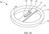
図1A及び図1Bは、本発明の第1の実施形態による外科クリップの斜視図であり、クリップがそれぞれ開いた形態、閉じた形態になっている。
【0026】
図2A及び図2Bは、本発明の第2の実施形態による外科クリップの斜視図であり、クリップがそれぞれ開いた形態、閉じた形態になっている。
【0027】
図3Aは、本発明の第3の実施形態による外科クリップの斜視図であり、クリップが開いた形態になっている。
【0028】
図3Bは、図3Aに示されている外科クリップの側面図である。
【0029】
図3Cは、図3Bに示されている外科クリップの断面図であり、クリップが閉じた形態になっている。
【0030】
図3Dは、図3Bに示されている外科クリップの断面図であり、クリップが閉じた形態になっており、切断要素及びこれと対になる対応要素が互いに押し付けられている。
【0031】
図4A及び図4Bは、それぞれ、本発明の第4の実施形態による外科クリップの斜視図、側面図であり、クリップが開いた形態になっている。
【0032】
図4Cは、図4Aに示されている外科クリップの側面図であり、クリップが閉じた形態になっている。
【0033】
図4Dは、図4Cに示されている外科クリップの側面図であり、切断要素及びこれと対になる対応要素が互いに押し付けられている。
【0034】
図4Eは、本発明の第5の実施形態による外科クリップの斜視図であり、クリップが開いた形態になっている。
【0035】
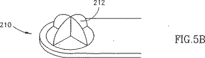
図5A及び図5Bは、それぞれ、図4Eに示されている実施形態による外科クリップにおいて使用され得る対応要素、切断要素の斜視図である。
【0036】
図5Cは、図1A及び図1Bの両方による外科クリップにおいて使用され得る切断要素及びこれに対応する対応要素の斜視図である。
【0037】
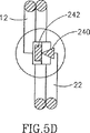
図5Dは、本発明による外科クリップの斜視図であり、別の実施形態の切断要素及び対応要素が使用されている。
【0038】
図5E、図5F、図5G、図5H及び図5Iは、本発明による外科クリップにおいて使用され得る切断要素及び対応要素の別の代替的な実施形態である。
【0039】
図6Aは、本発明の第6の実施形態による外科クリップの斜視図である。
【0040】
図6Bは、図6Aに示されている外科クリップの側面図であり、クリップが閉じた形態になっている。
【0041】
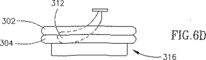
図6C及び図6Dは、図6Aに示されている外科クリップの側面図であり、クリップが閉じた位置になっており、それぞれ、切断要素が押圧されることにより対応要素と切断係合している状態、切断要素が対応要素との切断係合から解除された状態である。
【0042】
図7Aは、内部に図1A及び図1Bの本発明による外科クリップが配置された中空器官の斜視図であり、外科クリップは塑性状態になっている。
【0043】
図7Bは、図7Aに示されている中空器官及び外科クリップを線7B−7Bの方向に見た断面図である。
【0044】
図7Cは、図7Aに示されている中空器官及び外科クリップの図であり、外科クリップが弾性状態になっている。
【0045】
図7Dは、図7Cに示されている中空器官及び外科クリップを線7D−7Dの方向に見た断面図である。
【0046】
発明の詳細な説明
本発明は、クリップの縁全体に沿って器官組織を圧迫することによって、器官の一部同士の満足な接合又は吻合を保証すると共に、組織の一部を切断して胃腸器官の初期疎通部を形成するための器具を提供する、従来技術において公知となっているような少なくとも一部が形状記憶合金から形成されている外科クリップを提供することを目的とする。本発明は、さらに、本発明の外科クリップを使用して、胃腸管の器官部分のような器官部分の吻合を行うと共に、組織の一部を切断して胃腸管の初期疎通部を形成するための方法を提供することを目的とする。
【0047】
ここで、図面を参照すると、図1A及び図1Bは、全体に対して参照符号1を付された本発明の第1の実施形態による外科クリップを図示しており、外科クリップ10は、それぞれ、開いた形態、閉じた形態で示されている。外科クリップ10は、典型的には、ワイヤ状で、少なくとも一部が形状記憶合金から形成されており、それぞれ端部14及び24を有した一対のループ(輪)12及び22を含むようにコイル状形態となっている。ループ12及び22の各々はその端部からコイル状巻線に沿った中間点30までで完全な円を規定している。したがって、コイル状巻線は、ループ12の端部14からループ22の端部24まで2つの完全な円を規定している。本発明の外科クリップの様々な実施形態が円形状を規定するとして示されているが、本発明はそれに代えて楕円のような任意の閉じた幾何学的形状を規定してもよいことは当業者に認識されるであろう。
【0048】
少なくとも外科クリップ10の中間部分13は形状記憶合金から形成されており、外科クリップが予め定められた温度以下まで冷却されたときに、外科クリップが塑性状態となり、ループ12及び22が図1Aに示されている位置のように引き離され得るようになっている。外科クリップ10は、予め定められた温度以上まで加熱されたときに、弾性状態になり、ループ12及び22が図1Bに示されている位置のように互いに隣接するようになる。温度変化は形状記憶合金に影響を与えるので、温度変化については、図7A〜図7Dを参照して、さらに検討する。
【0049】
外科クリップ10のループ12及び22は一対のクロスバー(横断棒)16及び26を備えており、それぞれのクロスバー16及び26はそれぞれのループ12及び22を横断して延びている。クロスバー16及び26は、任意の適した手段によってそれぞれのループ12及び22に留められ得る。クロスバー16には穴18が形成され、クロスバー26は穴28の周囲を取り囲む刃部分48を有した中空切断要素20を備えている。切断要素20の刃部分48は、止まりばめされる(図1B)ような穴18に対する相対的形態及びサイズを有している。クロスバー16はループ12によって規定されている円に沿って位置する点32と点34との間に延びており、クロスバー26はループ22によって規定される円に沿って位置する点42と点44との間に延びている。ループ12に沿って点30から点32に至る距離は、ループ22に沿って端部24から点42に至る距離と同じである。同様に、ループ12に沿って端部14から点34に至る距離は、ループ22に沿って点30から点44に至る距離と同じである。よって、図1Bに示されているように、ループ12及び22が隣接するとき、クロスバー16及び26は互いに重なり合って位置し、切断要素20は穴18に位置合わせされる。クロスバー16及び26はそれぞれループ12及び22に対して特定の向きで示されているが、本発明の範囲から逸脱することなく、クロスバー16及び26が互いに重なり合って位置する限り任意の向きが可能であることは当業者に認識されよう。
【0050】
図1Bに示されているように、閉じた形態になっているとき、ループ12及び22が互いに隣接すると共に、クロスバー16及び26も互いに隣接し、切断要素20は穴18内にぴったり収まって配置される。よって、クロスバー16は切断要素20と対になる切断要素20の対応要素として機能する。
【0051】
図2A及び図2Bを参照すると、全体に対して参照符号110を付された本発明の第2の実施形態による外科クリップが示されており、この外科クリップがそれぞれ開いた形態及び閉じた形態で示されている。外科クリップ110は、形状記憶合金から形成された中間部分113を含む2つの完全な円からなるコイル状巻線を規定している点で外科クリップ10(図1A及び図1B)と類似であるが、外科クリップ110は、ループ12、22上にそれぞれクロスバー(横断棒)116、バー(棒)126を備えている。クロスバー116、バー126は、任意の適した手段によってそれぞれのループ12及び22に留められ得る。バー126は、バー126から延びる外科刃128を備え、外科クリップ110が閉じた形態になっているとき、外科刃128はクロスバー126に自身を押し付ける(図2B)。よって、クロスバー116は外科刃128と対になる外科刃128の対応要素として機能する。
【0052】
図3A〜図3Dは、全体に対して参照符号130を付された本発明の第3の実施形態による外科クリップを図示している。外科クリップ130は、形状記憶合金から形成された中間部分13を含んでおり、外科クリップ10と同様に、2つの完全な円からなるコイル状巻線を規定し、同様のループ12及び22を有している。しかしながら、本発明のこの実施形態では、外科クリップ130のループ22は、端部に刃134を有したL字形状アーム132の形態の切断要素133を備えており、このL字形状アーム132はループ22の中心に向かって延びている。ループ12は、端部にU字形状部分138を有したアーム137の形態の対応要素136を備えており、U字の開いた端部はループ12の中心の側に向いている。L字形状要素132、対応要素136は、それぞれ、任意の適した手段によって、ループ22、12に留められ得る。切断要素133及び対応要素136は本発明の目的に合った切断要素及び対応要素として機能する限り任意の他の適した形状を有するものとして構成され得ることは当業者に認識されよう。
【0053】
図3A及び図3Bは、中間部分13が塑性状態になっている外科クリップ130を示しており、ループ12及び22が引き離されている。図3C及び図3Dに示されているように、中間部分13が弾性状態になったとき、ループ12及び22は互いに対して押し付けられる。切断要素133の刃134は、図3Cに示されているように、対応要素136のU字形状部分138に近接してはいるがなお離間している状態で配置される。手作業で切断要素133及び対応要素136の両方にそれぞれ矢印A及び矢印Bの方向に外部圧力を付与することによって、これら要素が、図3Dに示されているように、接触するように互いに力を受け、刃134が対応要素136のU字形状部分138のほぼ中心において対応要素136に押し付けられる。切断要素133及び対応要素136は、解放された後、図3Cに示されている位置に戻ることを許容される。
【0054】
図4A、図4B、図4C及び図4Dは、全体に対して参照符号140を付された本発明の第4の実施形態による外科クリップを図示している。外科クリップ140は2つのリング状部分142及び144を含んでおり、これらリング状部分142及び144が中間部分150において互いに結合されている。所望であれば、外科クリップ140全体を形状記憶合金から形成することも可能であるが、少なくとも中間部分150が形状記憶合金から形成されることが不可欠である。リング状部分142、144は、それぞれ、クロスバー146、148を備えている。クロスバー146の中心には、クロスバー146を貫通して摺動可能に取り付けられている切断要素152が設けられている。切断要素152は、リング形状の頭部分156と、穴159を有した筒部分158とを含んでいる。クロスバー148は、切断要素152の筒状部分158と類似のサイズ及び形態の筒状穴154とクロスバー148のクロスバー146から遠い側に穴154周りに配置されたフランジ部分160とから成る形態の対応要素162を備えている。
【0055】
外科クリップ140の切断要素152及び対応要素162は特定のサイズ及び形状を有するとして示されているが、切断要素と対応要素との間に位置する組織を切り取る又は切断できる任意の適した形態の切断要素及び対応要素を使用することができることは当業者に認識されよう。
【0056】
図4A及び図4Bでは、塑性状態になっている外科クリップ140の中間部分150が示されており、リング状部分142及び144が引き離されている。図4C及び図4Dに示されているように、外科クリップ140の中間部分150が弾性状態になったとき、リング状部分142及び144は互いに対してきつく押し付けられ、切断要素152の筒状部分158が対応要素162の穴154に隣接して配置される。クロスバー146上の切断要素152の頭部分156に矢印Bの方向に圧力を付与すると共に対応要素162のフランジ部分160に矢印Cの方向に圧力を付与することにより、筒状部分158は、穴154内に押し込められ(図4D)、筒状部分158と穴154の内側表面との間での止まりばめによって所定の位置に保持される。
【0057】
切断要素133、対応要素136が、それぞれ、リング22、12に対して移動可能となっている外科クリップ130(図3A〜図3D)と対照的に、外科クリップ140では、切断要素136のみがリング状部分142に対して移動可能となっている一方、対応要素162はリング状部分144に対して移動しないことに留意するとよい。
【0058】
図4Eは、本発明の第5の実施形態による外科クリップを示している。外科クリップ170は、形状記憶合金から形成される中間部分150を含み且つリング状部分142及び144を備えている点において、外科クリップ140(図4A、図4B、図4C及び図4D)に類似である。しかしながら、リング状部分142、144は、それぞれ、リング状部分142、144に沿った対応する点からリング状部分の内側へ延びているアーム172、174を備えている。アーム172、174は、それぞれ、任意の適した手段によって、リング状部分142、144に留められ得る。アーム172の端部には、頭部178と穴181を有した筒状部分180とを有する切断要素176が形成されている。アーム174の端部は対応要素186を備え、対応要素186は、筒状部分182と、切断要素176の筒状部分180と類似のサイズ及び形態の筒状穴184とを有している。
【0059】
図4Eには、塑性状態になっている外科クリップ170の中間部分150が示されており、リング状部分142及び144が引き離されている。しかしながら、外科クリップ170の中間部分150が弾性状態になったとき(図示せず)、リング状部分142及び144は互いに対してきつく押圧され、切断要素176の筒状部分180が対応要素186の穴184に隣接して配置される。アーム172上の切断要素176の頭部分178と対応要素186の筒状部分182とに圧力を付与することによって、切断要素176の筒状部分180は、穴184に押し込められ、筒状部分180と穴184の内側表面との間の止まりばめによって所定の位置に保持される。図5A及び図5Bは、図4Eに示されている外科クリップ170において使用され得る全体に対して参照符号200を付された対応要素と全体に対して参照符号210を付された切断要素の斜視図である。対応要素200には、形態及びサイズが切断要素210の刃212に対応しているX字形状の穴202が設けられている。よって、本発明の装置において対応要素200及び切断要素210を使用する場合、外科クリップの中間部分が上述したように弾性状態になったときに、対応要素200及び切断要素210が互いに押圧され、刃212を穴202に押し込めることができる。
【0060】
図5Cに本発明の別の実施形態が図示されている。図5Cは、図1A及び図1Bの両方による外科クリップにおいて使用され得る切断要素220及び対応する対応要素230を示している。切断要素220は、楕円形状のベース部分222を備えており、ベース部分222はそこから突出している一対の針状刃224を有している。対応要素230は、形態及びサイズが切断要素220のベース部分222と類似の楕円形状のベース部分232と、ベース部分232から延びるフランジ234とを備えている。ベース部分232はさらに楕円形の穴236を有しており、この穴236の幅は刃224の幅と類似であり、その長さは一方の刃の外側縁端と他方の刃の外側縁端との間の距離に少なくとも等しくなっている。よって、本発明の装置において対応要素230及び切断要素220を使用する場合、外科クリップの中間部分が上述したように弾性状態になったときに、対応要素230及び切断要素220が互いに押圧され、刃224を穴236に押し込める。
【0061】
図5D、図5E、図5F、図5G、図5H及び図5Iは、特定の刃要素と対応要素の組み合わせ間の関係の幾つかの特定の例を示しており、これらの組み合わせで、図2〜図4に示されている本発明の実施形態において使用されている刃要素及び対応要素を置換することができる。図5Dに示されているように、装置の形状記憶合金が弾性状態になったときに、ループ12及び22が互いに対して押し付けられる。図5D及び図5Eは、平坦な表面の対応要素242及び244の各々と接触させられたときの刃240を示している。図5Fには、刃240と、刃240の先端部を収容するような形状に形成された凹部250を有した対応要素248とが示されている。図5Gは、刃246と、貫通して延びる筒状凹部254を有した対応要素252とを示している。凹部254は刃246の先端部256を受容するに十分な大きさになっている。しかしながら、刃246が凹部254内にさらに移動させられても、凹部254に進入した刃246の幅が凹部254の幅と等しくなる位置に刃246が到達すると、刃246の移動が停止させられる。図5Hでは、刃246の先端部を収容する形状に形成された三角形状凹部260を有した対応要素258が設けられている。図5Iは代替実施形態を示しており、刃要素及び対応要素の組み合わせが刃262の形態の一対の刃要素268によって置換されており、刃262は、ループ12及び22(図5D)が互いに押し付けられたときに接触し、各刃262の先端部264が他方の刃262の側部266に沿って位置するようになっている。
【0062】
図6A〜図6Dは、本発明の第6の実施形態による外科クリップ300を示している。外科クリップ300は2つのリング状部分302及び304を含んでおり、これらリング状部分302及び304が形状記憶合金から形成された中間部分306において互いに結合されている。リング状部分302は、回転可能な刃要素310を有し且つ中心からずれた偏心クロスバー308を備えている。切断要素310は、刃312と、頭部分314とを含んでおり、刃312は、頭部分314によって、リング状部分302の中心に向かって下方へ回転させられ得る。概略長方形状の間隙320を有した一対の平行バー(平行棒)318として構成された対応要素316がリング状部分304の中心を横断して設けられている。バー318は、間隙320が刃312を収容するに十分に広く且つ止まりばめとなるに十分に狭くなるように配置されている。対応要素316が切断刃312と共に使用するのに適した他の任意の対応要素によって置換され得ることは当業者に認識されよう。
【0063】
中間部分306が塑性状態になっているとき、リング状部分302及び304は図6Aに示されている位置に引き離されることが可能である。しかしながら、図6B〜図6Dに示されているように、外科クリップ300の中間部分306が弾性状態になっているとき、リング状部分302及び304は互いに対してきつく押し付けられる。図6Bに示されているように、切断要素310の頭部分314に対して概略矢印Dの方向に圧力を付与することによって、刃312は、下方に移動するようにクロスバー308周りに回転させられる。これにより、結果的に、切断要素310が図6Cに示されている位置になり、刃312が対応要素316の間隙320内に止まりばめされる。所望であれば、切断要素310は、付勢手段又は類似の手段を備えることができ、それにより、刃312が間隙320から引き出される又は押し出され、図6Dに示されているように自動的に上側の位置に戻されるようになる。
【0064】
図7A〜図7Dを参照すると、吻合により互いを接合することを所望されている中空器官50の部分52及び54が示されている。中空器官50は、吻合を要する結腸又は他の任意の中空器官とすることができる。あるいはまた、本発明の方法は、例えば結腸部分を胃に接続するといった第1の中空器官の一部を第2の中空器官に接続するために使用され得る。ここでは、外科クリップ10を参照して、本発明の方法を説明する。しかしながら、本発明による他の実施形態の外科クリップを用いることにより又は本発明による上述した要素のうちの任意のものを使用することにより、本発明の方法を実行することが可能であることは当業者に認識されよう。
【0065】
さらに、本発明によるクリップのような形状記憶合金を使用した装置を以下の2つの異なるタイプの装置のうちの一方のものとして記載することも可能であることは当業者に認識されよう。第1のタイプの装置は、室温以下に冷却されたときに容易に変形可能なマルテンサイト状態になると共に室温では完全又は部分的にオーステナイト状態をなし且つ室温と体温との間の何れかの温度となる上側相転移温度まで少なくとも加熱されると完全なオーステナイト状態になる形状記憶合金を使用する。第2のタイプの装置によれば、形状記憶合金は、装置が変形させられて取り付けられる室温で容易に変形可能なマルテンサイト状態になり、室温以上に加熱されると完全なオーステナイト状態になる。2つのタイプの装置の差は、形状記憶合金が容易に変形可能となる温度範囲である。よって、第2のタイプの形状記憶合金を含んだ装置を利用することにより、取り付けの際により高い自由度が許容される。以下で検討される本発明の方法は、第1のタイプの装置について説明される。
【0066】
図7A〜図7Dを再度参照すると、少なくとも外科クリップ10の形状記憶合金部分13は少なくとも下側相転移温度まで冷却され、従来技術で知られているように、形状記憶合金が下側相転移温度でマルテンサイト状態になり、よって、外科クリップ10の少なくとも中間部分13が塑性状態になる。下側相転移温度は、概括して言えば、−273℃より高い任意の温度となり得るが、より普遍的には、体温より以下の約25〜35℃であり、好ましくは約0℃である。ループ12及び22は手によって所望される距離だけ引き離され、器官50に挿入されるまで必要とされる長さの期間、冷却された状態で保存される。
【0067】
別々の器官部分52及び54の開いた端部56及び58が外科的にステープル又は例えば縫合糸72による縫合により閉鎖され、それにより、別々の閉鎖された端部56A及び58Aが形成される。器官50の部分52及び54が隣接して並び合った関係に互いを引き寄せられ、刺し穴64及び66の位置において、それぞれ、隣接する壁60及び62に穿孔が施され、刺し穴64及び66は隣接して位置する。刺し穴64及び66のサイズ及び形状は、器官部分52及び54のそれぞれの内部にループ12及び22を配置するのを容易にし得るようにするために、所望通り選択される。外科クリップ10は、刺し穴64及び66を介してそれぞれループ12及び22を挿入することによって、ループ12及び22が壁60及び62をそれぞれ跨ぐように器官部分52及び54の内部に位置するように器官部分52及び54に導入される。本発明の方法は、本明細書において、器官部分52及び54の両方が最初にステープル又は縫合によって閉じられている図7A〜図7Dに関して説明されているが、本発明の範囲を逸脱することなく、外科クリップを挿入した後に、器官部分52及び54の一方又は両方を縫合により閉じることが可能であることは当業者に理解されよう。
【0068】
器官50の部分52及び54の相対位置とそれらに対する外科クリップ10の相対位置は、外科クリップ10がオーステナイト状態になり且つ好ましくは体温以下である上側相転移温度に少なくとも等しい温度まで、器官50の温度が実際に外科クリップ10の中間部分13の温度を上昇させている間、維持されなくてはならない。外科クリップ10の中間部分13の温度が転移温度へ向かって上昇している間、ループ12及び22は収束(接近)を続け、その間に位置する器官壁60及び62の組織部分同士68及び70を互いに対して一層密接に押し付けていき続ける。組織部分68及び70は、ループ12及び22の間に位置する壁60及び62の部分によってそれぞれ規定される。よって、組織部分68及び70の各々は、形状及びサイズが外科クリップ10のループ12及び22と類似の領域として構成される。
【0069】
外科クリップ10の中間部分13の温度が上昇する比率は、例えば当該技術分野において公知となっている任意の方法により外科クリップ10を加熱することによって、速められ得る。
【0070】
外科クリップ10の中間部分13の温度がその転移温度以上に上昇させられると、外科クリップ10は図7C及び図7Dに示されているような弾性相に戻り、ループ12及び22が互いに対して押し付け合い、互いに対して固定された位置に壁60及び62を維持し続ける。同時に、切断要素20の刃48が穴18に押入れられ、それにより、サイズ及び形状が刃48と類似である組織部分68及び70の一部を切り取る。この組織の一部の切り取りにより、胃腸管の初期疎通部を形成する。
【0071】
切断要素133及び対応要素136が手による外部圧力によって作動可能となる図3A〜図3Dの外科クリップ130のような本発明の他の実施形態が使用されているとしても、このような外部圧力がこのために設計された器具(図示せず)の使用によるなど、当該技術分野で公知の任意の手段によって与えられてもよいことは当業者に認識されよう。
【0072】
組織の一部が組織部分68及び70から切り取られた後、器官50の部分52から部分54に至る経路のみがクロスバー16上の穴18と切断要素20の穴28とを介して通っている。
【0073】
外科クリップ10によって器官50の壁60及び62に作用する圧力により、それぞれの組織部分68及び70が互いに対して密接して押し付けられて、これら組織部分への血流が止まり、結果として、これら組織部分68及び70の壊死を引き起こす。組織部分68及び70が死ぬと、そのすぐ外側の組織部分68A及び70Aは、器官50の部分52及び54が接合され且つ器官50が1つの連続した器官として機能し得るように、修復し合う。組織部分68及び70が死ぬと、それら部分は、外科クリップ10と共に、壁60及び62から分離された状態になり、穴74(図7C)を生じさせる。死んだ組織部分68及び70は、外科クリップ10と共に、器官の通常の活動により、穴74を介して、器官50から外に送り出される。例えば、器官50が小腸であり且つ蠕動の方向が部分52から部分54へ向かう方向なら、外科クリップ10及び組織部分68及び70は、小腸の通常の活動によって、部分54を通って送り出される。
【0074】
所望であれば、図7A〜図7Dに示されている上述した手術方法における外科クリップ10に代えて、外科クリップ140(図4A〜図4D)及び170(図4E)の何れかを使用することが可能であることは、当業者に認識されよう。本発明のこれらの実施形態の何れかの使用には、外科クリップ(140,170)が器官50に導入され且つ中間部分が上述したように弾性(マルテンサイト)状態になった後、切断要素(152,176)及び対応要素(162,186)がそれぞれ手で切断係合状態にされることを要する。これにより、切断要素(152,176)をして対応要素(162,186)と共に、その間に位置する組織の一部を切り取らせる。切り取られた組織のサイズ及び形状は筒状部分(158,180)のそれと類似である。この組織の一部の切り取りにより、胃腸管の初期疎通部を形成する。
【0075】
あるいはまた、所望であれば、外科クリップ110(図2A及び図2B)、130(図3A〜図3D)及び300(図6A〜図6D)の何れかを上述した外科処置において使用することができる。外科クリップ110の使用は、外科クリップ110が図2A及び図2Bに関して上述したように弾性状態になったときに刃128がクロスバー116と係合して切断を行うので、刃128及びクロスバー116がその間に位置する組織の一部を貫通する切開口を自動的に形成することが可能となる。外科クリップ130及び300の何れかの使用には、外科クリップ(130,300)が器官50に導入され且つ上述したように弾性状態になった後、切断要素(133,310)及び対応要素(136,316)がそれぞれ手で係合されて切断を行うことを要する。これにより、切断要素(133,310)をして対応要素(136,316)と共に、その間に位置する組織の一部を貫通して切開が行われる。組織の一部を貫通するこの切開により胃腸管の初期疎通部を形成する。所望であれば、外科クリップ(110,130,300)のうちの何れかにより切開が行われた後、少し広げられてもよいが、組織部分68及び70の全領域にまで広げられるべきではない。
【0076】
上述した外科処置において使用される外科クリップのサイズ及び形状と器官に結果的に形成される穴のサイズ及び形状との間には直接的な関係があることは、当業者には認識されよう。したがって、所望されるサイズ及び形状の穴を得るために特定のサイズ及び形状のクリップを用いて上記処置を行うことを選択することが可能である。
【0077】
本発明は、単に具体例として上記で示され説明されたものによって、制限を受けるものではないことは、当業者に了解されよう。むしろ、本発明の範囲は特許請求の範囲のみによって制限を受ける。
【図面の簡単な説明】
【図1A】 本発明の第1の実施形態による外科クリップの斜視図であり、クリップが開いた形態になっている。
【図1B】 本発明の第1の実施形態による外科クリップの斜視図であり、クリップが閉じた形態になっている。
【図2A】 本発明の第2の実施形態による外科クリップの斜視図であり、クリップが開いた形態になっている。
【図2B】 本発明の第2の実施形態による外科クリップの斜視図であり、クリップが閉じた形態になっている。
【図3A】 本発明の第3の実施形態による外科クリップの斜視図であり、クリップが開いた形態になっている。
【図3B】 図3Aに示されている外科クリップの側面図である。
【図3C】 図3Bに示されている外科クリップの断面図であり、クリップが閉じた形態になっている。
【図3D】 図3Bに示されている外科クリップの断面図であり、クリップが閉じた形態になっており、切断要素及びこれと対になる対応要素が互いに押し付けられている。
【図4A】 本発明の第4の実施形態による外科クリップの斜視図であり、クリップが開いた形態になっている。
【図4B】 本発明の第4の実施形態による外科クリップの側面図であり、クリップが開いた形態になっている。
【図4C】 図4Aに示されている外科クリップの側面図であり、クリップが閉じた形態になっている。
【図4D】 図4Cに示されている外科クリップの側面図であり、切断要素及びこれと対になる対応要素が互いに押し付けられている。
【図4E】 本発明の第5の実施形態による外科クリップの斜視図であり、クリップが開いた形態になっている。
【図5A】 図4Eに示されている実施形態による外科クリップにおいて使用され得る対応要素の斜視図である。
【図5B】 図4Eに示されている実施形態による外科クリップにおいて使用され得る切断要素の斜視図である。
【図5C】 図1A及び図1Bの何れかによる外科クリップにおいて使用され得る切断要素及びこれに対応する対応要素の斜視図である。
【図5D】 本発明による外科クリップの斜視図であり、別の実施形態の切断要素及び対応要素が使用されている。
【図5E】 本発明による外科クリップにおいて使用され得る切断要素及び対応要素の別の代替的な実施形態である。
【図5F】 本発明による外科クリップにおいて使用され得る切断要素及び対応要素の別の代替的な実施形態である。
【図5G】 本発明による外科クリップにおいて使用され得る切断要素及び対応要素の別の代替的な実施形態である。
【図5H】 本発明による外科クリップにおいて使用され得る切断要素及び対応要素の別の代替的な実施形態である。
【図5I】 本発明による外科クリップにおいて使用され得る切断要素及び対応要素の別の代替的な実施形態である。
【図6A】 本発明の第6の実施形態による外科クリップの斜視図である。
【図6B】 図6Aに示されている外科クリップの側面図であり、クリップが閉じた形態になっている。
【図6C】 図6Aに示されている外科クリップの側面図であり、クリップが閉じた位置になっており、切断要素が押圧され対応要素と切断係合している状態である。
【図6D】 図6Aに示されている外科クリップの側面図であり、クリップが閉じた位置になっており、切断要素が対応要素との切断係合から解除された状態である。
【図7A】 内部に図1A及び図1Bの本発明による外科クリップが配置された中空器官の斜視図であり、外科クリップは塑性状態になっている。
【図7B】 図7Aに示されている中空器官及び外科クリップを線7B−7Bの方向に見た断面図である。
【図7C】 図7Aに示されている中空器官及び外科クリップの図であり、外科クリップが弾性状態になっている。
【図7D】 図7Cに示されている中空器官及び外科クリップを線7D−7Dの方向に見た断面図である。[0001]
Field of Invention
The present invention generally relates to the field of surgical clips, and more particularly to the field of surgical clips formed from shape memory alloys.
[0002]
Background of the Invention
In the art, several methods for joining parts of hollow organs such as the gastrointestinal tract are known. These include yarns used for manual stitching (hand stitching), staples used for mechanical stitching, compression rings, and compression clips.
[0003]
Hand suturing is widely known and relatively inexpensive, but the success depends largely on the skill of the surgeon. Another disadvantage is the high incidence of postoperative complications. In addition, when the organ is sutured, the organ tissue lacks smoothness, and if the sutured organ is part of the gastrointestinal tract, this lack of smoothness prevents peristalsis in the sutured area. It is done.
[0004]
Staples used for mechanical suturing ensure reliable tissue bonding and reduce the time required for surgery. However, such staples cannot be reused, and so many different types and sizes are required, resulting in expensive staples. Also, after healing, the metal staples remain in place along the edges of the suture, reducing the elasticity of the joint and adversely affecting peristalsis if the sutured organ is part of the gastrointestinal tract. Effect.
[0005]
Joining using compression devices (compressors) such as rings and clips ensures the best organ sealing and post-operative function. Two types of compression devices are known, namely a ring made of absorbent plastic and a clip made of memory alloy. Plastic rings are cumbersome and expensive. In addition, the compressive force is applied to the joint only instantaneously and decreases when the tissue is crushed. Clips made from shape memory alloys will be in equilibrium with body temperature, and when the clip recovers its memorized shape due to the unique properties of the alloy, parts of the tissue can be pressed against each other become.
[0006]
Since clips made from memory alloy materials have many advantages over other devices, their development has increased in recent years. Such clips are simple in structure, inexpensive, small in size, have universal quality and are self-extracted from the gastrointestinal tract.
[0007]
It is known in the art to provide surgical clamping clips that apply a clamping force to a site such as a blood vessel to reduce the cross-sectional area of that site. Also provided is a surgical clamping clip formed from a shape memory alloy that deforms to a closed configuration when heat is applied to increase the clamping force applied when heat is applied. This is also known. For example, US Pat. No. 5,171,252 discloses a surgical clamping clip formed from a shape memory alloy. The device disclosed in the specification of this US patent includes separate legs that close tightly around a predetermined site. Such devices have limited applications, such as for tightening blood vessels, and are not suitable for joining portions of the gastrointestinal tract.
[0008]
EP 0,326,757 discloses an apparatus for anastomosing the digestive tract, which includes a plurality of U-shaped retaining clips disposed around a soluble support tube. . The support tube is disposed inside a portion to be joined of the digestive tract and includes an outer groove, and a U-shaped holding clip is disposed around the outer groove. The retaining clip is formed from a shape memory alloy and its open end closes at a predetermined temperature to join the ends of the digestive tract. When the ends of the digestive tract are joined, the support tube dissolves. Such a device is inconvenient in that it requires a plurality of clips to be properly placed at the same time. Further, since a plurality of portions of the digestive tract are joined by a plurality of clips, there is no guarantee that the resulting joined portion will be smooth.
[0009]
US Pat. No. 1,186,199 discloses a memory alloy clip consisting of two parallel coils used to join parts of a hollow organ, such as an organ of the gastrointestinal tract. The parts of the organ to be joined are aligned and each of the plastic coils is inserted into a puncture formed in the wall of one of the organ parts. As each coil is heated, it is positioned to squeeze the aligned walls located between it and continue to hold portions of the walls within the adjacent loops of the coil. Thereafter, an incision is formed through the portion of the wall held in the loop of the coil, and a passage is formed between the two organ parts. The puncture hole in the organ wall must then be closed with a surgical suture with a nodal surgical suture.
[0010]
The major disadvantage of the known memory alloy clips is that they can only compress about 80-85% of the edge of the joint, thus requiring additional hand suturing, and this hand suturing is necessary for the joint during the healing period. It is to reduce the sealing properties and the elasticity of the joint during the postoperative period. This additional stitching is also problematic because it must be performed across the seam including part of the clip, thereby making it difficult to seal and anastomoses the organ parts. In addition, prior art clips, once placed, perform yet another operation, an operation that forms an incision through tissue to form a passageway between two organ parts joined by the clip. It needs to be done.
[0011]
Thus, it facilitates almost the entire compression around the joint between the parts of the organ to be joined, eliminates the need for additional hand suturing, smooth sealing of the joint during the healing period and postoperative period There is a need for a surgical device that ensures the elasticity of the joints at the same time. Furthermore, there is a need for a surgical device that, once deployed, allows a passage to be formed between two organ parts that are joined together without requiring further surgery on the organ. Exists.
[0012]
Summary of the Invention
The present invention seeks to provide an improved surgical clip formed from a shape memory alloy and a method of joining two parts of a hollow organ that overcomes the disadvantages of the prior art.
[0013]
Thus, according to a preferred embodiment of the present invention, a first length of wire defining a closed geometric shape with a central opening, and a wire of form and size of said first length A second length of wire that is similar and defines a closed geometry, and is complete when the first length of wire and the second length of wire are placed side by side A second length of wire configured to overlap the intermediate portion, and an intermediate portion located between the first length of wire and the second length of wire and formed from a shape memory alloy And a cutting element associated with the first length of wire and a correspondence associated with the second length of wire and engaged with the cutting element for cutting. With elements, The cutting element is for forming an initial communicating portion of the gastrointestinal tract when engaged with the corresponding element; When the temperature exceeds the first temperature, the wire of the first length and the wire of the second length are arranged in a closed position and the shape memory alloy is in an elastic state, When the temperature becomes equal to or lower than a second temperature lower than the first temperature, the shape memory alloy is in a plastic state, whereby the first length wire and the second length wire are separated from each other. The first length of wire and the second length when heated to a temperature at least equal to the first temperature. The wires return to the side-by-side closed position, thereby applying a compressive force to the tissue located between the first length of wire and the second length of wire, Surgical clip at least partially formed from a shape memory alloy Flops are provided.
[0014]
Further, according to the first aspect of the present invention, the surgical clip further includes a pressing device for causing the cutting element to engage with the corresponding element by pressing the cutting element to perform cutting. When the temperature becomes higher than the temperature, the pressing device presses the cutting element to engage with the corresponding element to perform cutting.
[0015]
According to an alternative embodiment of the present invention, the surgical clip further comprises a pressing device for causing the cutting element to engage with the corresponding element by pressing the cutting element to cause the cutting to be performed at a temperature above the first temperature. When this happens, the pressing device can be activated by external pressure.
[0016]
Furthermore, according to an embodiment of the present invention, the geometric shape of the surgical clip is circular.
[0017]
Also according to an alternative embodiment of the present invention, the surgical clip has an oval geometric shape.
[0018]
According to an embodiment of the present invention, the first length of wire and the second length of wire are defined by a continuous coil.
[0019]
Still further in accordance with an alternative embodiment of the present invention, the first length wire and the second length wire are two separate length wires, each having a closed geometry. Is specified.
[0020]
Still further in accordance with a preferred embodiment of the present invention the corresponding element also includes a cutting element.
[0021]
According to the present invention, (a) a first length of wire defining a closed geometric shape with a central opening and a form and size similar to the first length of wire. And a second length of wire defining a closed geometric shape so that the first length and the second length of wire are completely overlapped when placed side by side. A second length of wire, an intermediate portion located between the first length of wire and the second length of wire and formed of a shape memory alloy, and A cutting element associated with the first length of wire, and a corresponding element associated with the second length of wire and disposed to engage and cut the cutting element. Providing a surgical clip comprising and at least partially formed from a shape memory alloy; (b) The intermediate portion is in a plastic state, whereby the first length of wire and the second length of wire are moved to a separated position and the separated position can be maintained. Cooling at least the intermediate portion to a temperature below the lower phase transition temperature; (c) manually pulling the first length of wire and the second length of wire apart; ) Pulling together portions of the gastrointestinal tract where at least one is an open end and anastomosis is desired, such that the portions are in an adjacent side-by-side relationship; and (e) the gastrointestinal tract Surgically closing the open end of the portion; (f) forming a puncture hole adjacent to the walls of the gastrointestinal tract adjacent to each other; and (g) the wall of each portion of the gastrointestinal tract being the first. One length of wire and the second Introducing the surgical clip through the puncture hole so as to be positioned between the wire and (h) at least the temperature of the intermediate portion up to a temperature above the upper phase transition temperature at which the intermediate portion becomes elastic While maintaining the relative position of the portions of the gastrointestinal tract and the position of the surgical clip relative to the portion of the gastrointestinal tract while raising the first length of wire and the second length Anastomosis of the gastrointestinal tract comprising: aligning the wires in juxtaposition and applying a compressive force to tissue located between the first length of wire and the second length of wire A method is provided.
[0022]
Furthermore, according to a preferred embodiment of the method of the present invention, in step (h), the temperature of the surgical clip is raised to a temperature above the upper phase transition temperature by heating the gastrointestinal tract.
[0023]
In addition, according to a preferred embodiment of the method of the present invention, the surgical clip further comprises a pressing device for causing the cutting element to engage with the corresponding element by pressing the cutting element and to perform the cutting. When the temperature exceeds the upper phase transition temperature, the cutting element is pressed to engage with the corresponding element to perform cutting, whereby the first length of wire and the second phase transition temperature are increased. Forming an opening in the tissue located between the length of wire and generating an initial communication portion of the gastrointestinal tract, wherein the method includes an additional step of expanding the opening after step (h) Including.
[0024]
Brief Description of Drawings
The present invention will be more fully understood and appreciated from the following detailed description.
[0025]
1A and 1B are perspective views of a surgical clip according to a first embodiment of the present invention, wherein the clip is in an open configuration and a closed configuration, respectively.
[0026]
2A and 2B are perspective views of a surgical clip according to a second embodiment of the present invention, wherein the clip is in an open configuration and a closed configuration, respectively.
[0027]
FIG. 3A is a perspective view of a surgical clip according to a third embodiment of the present invention, with the clip open.
[0028]
FIG. 3B is a side view of the surgical clip shown in FIG. 3A.
[0029]
FIG. 3C is a cross-sectional view of the surgical clip shown in FIG. 3B with the clip in a closed configuration.
[0030]
FIG. 3D is a cross-sectional view of the surgical clip shown in FIG. 3B, with the clip in a closed configuration, with the cutting element and its counterpart element pressed against each other.
[0031]
4A and 4B are a perspective view and a side view, respectively, of a surgical clip according to a fourth embodiment of the present invention, in which the clip is in an open configuration.
[0032]
FIG. 4C is a side view of the surgical clip shown in FIG. 4A, with the clip in a closed configuration.
[0033]
FIG. 4D is a side view of the surgical clip shown in FIG. 4C, with the cutting element and its counterpart element pressed against each other.
[0034]
FIG. 4E is a perspective view of a surgical clip according to a fifth embodiment of the present invention, with the clip open.
[0035]
5A and 5B are perspective views of corresponding elements, cutting elements, respectively, that may be used in the surgical clip according to the embodiment shown in FIG. 4E.
[0036]
FIG. 5C is a perspective view of a cutting element and corresponding element that may be used in the surgical clip according to both FIGS. 1A and 1B.
[0037]
FIG. 5D is a perspective view of a surgical clip according to the present invention, wherein another embodiment of a cutting element and a corresponding element are used.
[0038]
5E, 5F, 5G, 5H and 5I are another alternative embodiment of a cutting element and corresponding element that may be used in a surgical clip according to the present invention.
[0039]
FIG. 6A is a perspective view of a surgical clip according to a sixth embodiment of the present invention.
[0040]
6B is a side view of the surgical clip shown in FIG. 6A, with the clip in a closed configuration.
[0041]
6C and 6D are side views of the surgical clip shown in FIG. 6A, wherein the clip is in a closed position, each in a cutting engagement with a corresponding element by pressing the cutting element. A state where the cutting element is released from the cutting engagement with the corresponding element.
[0042]
FIG. 7A is a perspective view of a hollow organ having a surgical clip according to the present invention of FIGS. 1A and 1B disposed therein, wherein the surgical clip is in a plastic state.
[0043]
FIG. 7B is a cross-sectional view of the hollow organ and surgical clip shown in FIG. 7A in the direction of
[0044]
FIG. 7C is an illustration of the hollow organ and surgical clip shown in FIG. 7A, with the surgical clip in an elastic state.
[0045]
7D is a cross-sectional view of the hollow organ and surgical clip shown in FIG. 7C as viewed in the direction of line 7D-7D.
[0046]
Detailed Description of the Invention
The present invention ensures a satisfactory joint or anastomosis between parts of the organ by compressing the organ tissue along the entire edge of the clip and cuts off the portion of tissue to provide an initial passage for the gastrointestinal organ. It is an object to provide a surgical clip which is formed at least in part from a shape memory alloy as known in the prior art, providing an instrument for forming. The present invention further uses the surgical clip of the present invention to perform an anastomosis of an organ part, such as an organ part of the gastrointestinal tract, and to cut a portion of tissue to form an initial communication portion of the gastrointestinal tract The purpose is to provide a method.
[0047]
Referring now to the drawings, FIGS. 1A and 1B illustrate a surgical clip according to a first embodiment of the present invention, generally designated by reference numeral 1, wherein the
[0048]
At least the
[0049]
The
[0050]
As shown in FIG. 1B, when in the closed configuration, the
[0051]
Referring to FIGS. 2A and 2B, there is shown a surgical clip according to a second embodiment of the present invention, generally designated by
[0052]
3A-3D illustrate a surgical clip according to a third embodiment of the present invention, generally designated by
[0053]
3A and 3B show the
[0054]
4A, 4B, 4C and 4D illustrate a surgical clip according to a fourth embodiment of the present invention, generally designated by
[0055]
Although the
[0056]
4A and 4B show the
[0057]
In contrast to surgical clip 130 (FIGS. 3A-3D) in which
[0058]
FIG. 4E shows a surgical clip according to a fifth embodiment of the present invention.
[0059]
FIG. 4E shows the
[0060]
FIG. 5C illustrates another embodiment of the present invention. FIG. 5C shows a
[0061]
FIGS. 5D, 5E, 5F, 5G, 5H and 5I show some specific examples of relationships between specific blade elements and corresponding element combinations, and in these combinations, FIG. The blade elements and corresponding elements used in the embodiment of the invention shown in FIG. 4 can be replaced. As shown in FIG. 5D, when the shape memory alloy of the device is in an elastic state, the
[0062]
6A-6D show a
[0063]
When
[0064]
Referring to FIGS. 7A-7D, there are shown
[0065]
Furthermore, those skilled in the art will recognize that a device using a shape memory alloy such as a clip according to the present invention can be described as one of the following two different types of devices. The first type of device is in a martensite state that is easily deformable when cooled below room temperature and is fully or partially austenitic at room temperature and any temperature between room temperature and body temperature. A shape memory alloy is used that attains a complete austenitic state when heated to at least the upper phase transition temperature. According to the second type of device, the shape memory alloy is in a martensitic state that can be easily deformed at room temperature when the device is deformed and attached, and in a fully austenitic state when heated above room temperature. The difference between the two types of devices is the temperature range in which the shape memory alloy can be easily deformed. Thus, by using an apparatus that includes the second type of shape memory alloy, a higher degree of freedom is allowed during attachment. The inventive method discussed below is described for a first type of apparatus.
[0066]
Referring again to FIGS. 7A-7D, at least the shape
[0067]
The open ends 56 and 58 of the
[0068]
The relative position of the
[0069]
The rate at which the temperature of the
[0070]
When the temperature of the
[0071]
Even if other embodiments of the present invention are used, such as the
[0072]
After a portion of tissue has been cut from
[0073]
The pressure exerted on the
[0074]
If desired, use one of surgical clips 140 (FIGS. 4A-4D) and 170 (FIG. 4E) in place of
[0075]
Alternatively, if desired, any of surgical clips 110 (FIGS. 2A and 2B), 130 (FIGS. 3A-3D) and 300 (FIGS. 6A-6D) can be used in the surgical procedures described above. . The use of the
[0076]
One skilled in the art will recognize that there is a direct relationship between the size and shape of the surgical clip used in the surgical procedure described above and the size and shape of the resulting hole in the organ. Thus, it is possible to choose to perform the procedure using a clip of a particular size and shape to obtain a hole of the desired size and shape.
[0077]
It will be appreciated by persons skilled in the art that the present invention is not limited by what has been shown and described above by way of example only. Rather, the scope of the present invention is limited only by the claims.
[Brief description of the drawings]
1A is a perspective view of a surgical clip according to a first embodiment of the present invention, with the clip in an open configuration. FIG.
FIG. 1B is a perspective view of a surgical clip according to a first embodiment of the present invention, with the clip in a closed configuration.
FIG. 2A is a perspective view of a surgical clip according to a second embodiment of the present invention, with the clip in an open configuration.
FIG. 2B is a perspective view of a surgical clip according to a second embodiment of the present invention, with the clip in a closed configuration.
FIG. 3A is a perspective view of a surgical clip according to a third embodiment of the present invention, with the clip in an open configuration.
3B is a side view of the surgical clip shown in FIG. 3A.
3C is a cross-sectional view of the surgical clip shown in FIG. 3B with the clip in a closed configuration.
3D is a cross-sectional view of the surgical clip shown in FIG. 3B, with the clip in a closed configuration, with the cutting element and its mating counterpart element pressed against each other.
4A is a perspective view of a surgical clip according to a fourth embodiment of the present invention, with the clip in an open configuration. FIG.
FIG. 4B is a side view of a surgical clip according to a fourth embodiment of the present invention, with the clip in an open configuration.
4C is a side view of the surgical clip shown in FIG. 4A with the clip in a closed configuration. FIG.
4D is a side view of the surgical clip shown in FIG. 4C, with the cutting element and its mating counterpart element pressed against each other.
4E is a perspective view of a surgical clip according to a fifth embodiment of the present invention, with the clip in an open configuration. FIG.
5A is a perspective view of a corresponding element that may be used in a surgical clip according to the embodiment shown in FIG. 4E. FIG.
FIG. 5B is a perspective view of a cutting element that may be used in the surgical clip according to the embodiment shown in FIG. 4E.
5C is a perspective view of a cutting element and corresponding element that may be used in a surgical clip according to any of FIGS. 1A and 1B. FIG.
FIG. 5D is a perspective view of a surgical clip according to the present invention, using another embodiment of a cutting element and a corresponding element.
FIG. 5E is another alternative embodiment of a cutting element and corresponding element that may be used in a surgical clip according to the present invention.
FIG. 5F is another alternative embodiment of a cutting element and corresponding element that may be used in a surgical clip according to the present invention.
FIG. 5G is another alternative embodiment of a cutting element and corresponding element that may be used in a surgical clip according to the present invention.
FIG. 5H is another alternative embodiment of a cutting element and corresponding element that may be used in a surgical clip according to the present invention.
FIG. 5I is another alternative embodiment of a cutting element and corresponding element that may be used in a surgical clip according to the present invention.
6A is a perspective view of a surgical clip according to a sixth embodiment of the present invention. FIG.
6B is a side view of the surgical clip shown in FIG. 6A, with the clip in a closed configuration.
6C is a side view of the surgical clip shown in FIG. 6A, with the clip in a closed position, with the cutting element pressed and in cutting engagement with the corresponding element.
6D is a side view of the surgical clip shown in FIG. 6A, with the clip in a closed position, with the cutting element released from cutting engagement with the corresponding element.
7A is a perspective view of a hollow organ having a surgical clip according to the present invention of FIGS. 1A and 1B disposed therein, wherein the surgical clip is in a plastic state. FIG.
7B is a cross-sectional view of the hollow organ and surgical clip shown in FIG. 7A as viewed in the direction of
7C is a view of the hollow organ and surgical clip shown in FIG. 7A, with the surgical clip in an elastic state.
7D is a cross-sectional view of the hollow organ and surgical clip shown in FIG. 7C as viewed in the direction of line 7D-7D.
Claims (8)
形態及び大きさが前記第1の長さのワイヤと類似であり且つ閉じた幾何学的形状を規定する第2の長さのワイヤであって、第1の長さのワイヤと第2の長さのワイヤとが並べ合わせて配置されたときに完全に重なり合うようになっている第2の長さのワイヤと、
前記第1の長さのワイヤと前記第2の長さのワイヤとの間に位置し、形状記憶合金から形成されている中間部分と、
前記第1の長さのワイヤと連係している切断要素と、
前記第2の長さのワイヤと連係しており、前記切断要素と係合して切断を行うように配置された対応要素と、
を備え、前記切断要素が、前記対応要素と係合したときに胃腸管の初期疎通部を形成するためのものであり、第1の温度以上になったときに、前記第1の長さのワイヤと前記第2の長さのワイヤとが並び合って閉じた位置に配置され且つ前記形状記憶合金が弾性状態になり、前記第1の温度より低い第2の温度以下になったときに、前記形状記憶合金が塑性状態になり、それにより、前記第1の長さのワイヤ及び前記第2の長さのワイヤが離間した位置に移動させられてその離間した位置を保持することが可能となり、前記第1の温度と少なくとも等しい温度まで加熱されたときに、前記第1の長さのワイヤ及び前記第2の長さのワイヤが前記並び合って閉じた位置に戻り、それにより、前記第1の長さのワイヤと前記第2の長さのワイヤとの間に位置する組織に圧縮力を付与するようにした、少なくとも一部が形状記憶合金から形成される外科クリップ。A first length of wire defining a closed geometry having a central opening;
A second length of wire that is similar in shape and size to the first length of wire and that defines a closed geometry, the first length of wire and the second length of wire A second length of wire that is configured to completely overlap when the wire is placed side by side;
An intermediate portion located between the first length of wire and the second length of wire and formed from a shape memory alloy;
A cutting element associated with the first length of wire;
A corresponding element associated with the second length of wire and arranged to engage and cut with the cutting element;
When the cutting element is engaged with the corresponding element to form an initial communication portion of the gastrointestinal tract, and when the temperature exceeds a first temperature, the first length When the wire and the second length of wire are arranged side by side and placed in a closed position and the shape memory alloy becomes elastic and falls below a second temperature lower than the first temperature, The shape memory alloy is in a plastic state, so that the first length of wire and the second length of wire can be moved to a spaced position to hold the spaced position. , When heated to a temperature at least equal to the first temperature, the first length of wire and the second length of wire return to the side-by-side closed position, whereby the first length A first length of wire and a second length of wire; Was to impart a compressive force to tissue located between the surgical clip is formed at least partially from a shape memory alloy.
Applications Claiming Priority (2)
| Application Number | Priority Date | Filing Date | Title |
|---|---|---|---|
| IL13670200A IL136702A (en) | 2000-06-12 | 2000-06-12 | Surgical clip |
| PCT/IL2001/000525 WO2001095783A2 (en) | 2000-06-12 | 2001-06-07 | Surgical clip |
Publications (3)
| Publication Number | Publication Date |
|---|---|
| JP2004503276A JP2004503276A (en) | 2004-02-05 |
| JP2004503276A5 JP2004503276A5 (en) | 2005-02-24 |
| JP3742386B2 true JP3742386B2 (en) | 2006-02-01 |
Family
ID=11074254
Family Applications (1)
| Application Number | Title | Priority Date | Filing Date |
|---|---|---|---|
| JP2002509972A Expired - Fee Related JP3742386B2 (en) | 2000-06-12 | 2001-06-07 | Surgical clip |
Country Status (6)
| Country | Link |
|---|---|
| EP (1) | EP1301129B1 (en) |
| JP (1) | JP3742386B2 (en) |
| CN (1) | CN1232228C (en) |
| AT (1) | ATE441365T1 (en) |
| CA (1) | CA2411530C (en) |
| DE (1) | DE60139782D1 (en) |
Families Citing this family (13)
| Publication number | Priority date | Publication date | Assignee | Title |
|---|---|---|---|---|
| EP1370204B1 (en) | 2001-02-23 | 2006-08-30 | Refocus Ocular, Inc. | System for making incisions for scleral eye implants |
| US20070088412A1 (en) * | 2005-10-13 | 2007-04-19 | Intelifuse, Inc., A Corporation Of The State Of Delaware | System and device for heating or cooling shape memory surgical devices |
| US8083759B2 (en) | 2007-11-02 | 2011-12-27 | Refocus Ocular, Inc. | Apparatuses and methods for forming incisions in ocular tissue |
| CN102292013B (en) * | 2008-09-05 | 2015-05-27 | 卡内基梅隆大学 | Multi-linked endoscopic device with spherical distal assembly |
| KR101604080B1 (en) | 2009-07-21 | 2016-03-17 | 삼성전자주식회사 | Blood vessel pressing cuff, blood pressure measuring apparatus with the blood vessel pressing cuff, and blood pressure measuring method using the blood pressure measuring apparatus |
| US9687229B2 (en) * | 2010-03-11 | 2017-06-27 | Microkoll Inc. | Apparatus and method for tissue adhesion |
| US8597318B2 (en) | 2011-08-08 | 2013-12-03 | Refocus Group, Inc. | Apparatus and method for forming incisions in ocular tissue |
| WO2017104475A1 (en) | 2015-12-18 | 2017-06-22 | 株式会社カネカ | Connector, medical clip device, and production method for medical clip device |
| US11304698B2 (en) | 2016-07-25 | 2022-04-19 | Virender K. Sharma | Cardiac shunt device and delivery system |
| EP3487418A4 (en) | 2016-07-25 | 2020-04-08 | Virender K. Sharma | Magnetic anastomosis device delivery system |
| US10555725B2 (en) * | 2016-09-29 | 2020-02-11 | Gyrus Acmi, Inc. | Thermal mechanism to prevent reprocessing or reuse of mechanical surgical devices |
| EP3568089B1 (en) | 2017-01-11 | 2021-09-15 | Virender K. Sharma | Cardiac shunt device and delivery system |
| KR20200044799A (en) | 2017-08-23 | 2020-04-29 | 리포쿠스 그룹 인코포레이티드 | Surgical tools and associated devices and methods for forming incisions in ocular tissue with tips that provide visibility |
Family Cites Families (5)
| Publication number | Priority date | Publication date | Assignee | Title |
|---|---|---|---|---|
| US5222963A (en) * | 1991-01-17 | 1993-06-29 | Ethicon, Inc. | Pull-through circular anastomosic intraluminal stapler with absorbable fastener means |
| US5171252A (en) * | 1991-02-05 | 1992-12-15 | Friedland Thomas W | Surgical fastening clip formed of a shape memory alloy, a method of making such a clip and a method of using such a clip |
| US5591173A (en) * | 1994-07-28 | 1997-01-07 | Michael Schifano | Schifano obstetric scissors |
| IL119911A (en) * | 1996-12-25 | 2001-03-19 | Niti Alloys Tech Ltd | Surgical clip |
| IL132635A0 (en) * | 1999-10-28 | 2001-03-19 | Niti Alloys Tech Ltd | Shape memory alloy clip and method of use thereof |
-
2001
- 2001-06-07 CA CA002411530A patent/CA2411530C/en not_active Expired - Fee Related
- 2001-06-07 AT AT01938537T patent/ATE441365T1/en not_active IP Right Cessation
- 2001-06-07 DE DE60139782T patent/DE60139782D1/en not_active Expired - Lifetime
- 2001-06-07 JP JP2002509972A patent/JP3742386B2/en not_active Expired - Fee Related
- 2001-06-07 EP EP01938537A patent/EP1301129B1/en not_active Expired - Lifetime
- 2001-06-07 CN CNB018109497A patent/CN1232228C/en not_active Expired - Fee Related
Also Published As
| Publication number | Publication date |
|---|---|
| CN1436060A (en) | 2003-08-13 |
| CA2411530A1 (en) | 2001-12-20 |
| EP1301129B1 (en) | 2009-09-02 |
| JP2004503276A (en) | 2004-02-05 |
| EP1301129A2 (en) | 2003-04-16 |
| CA2411530C (en) | 2009-07-28 |
| CN1232228C (en) | 2005-12-21 |
| DE60139782D1 (en) | 2009-10-15 |
| ATE441365T1 (en) | 2009-09-15 |
| EP1301129A4 (en) | 2008-10-22 |
Similar Documents
| Publication | Publication Date | Title |
|---|---|---|
| US6402765B1 (en) | Surgical clip | |
| JP3725825B2 (en) | Shape memory alloy clip and method of using the same | |
| US6171320B1 (en) | Surgical clip | |
| JP3742386B2 (en) | Surgical clip | |
| US5752966A (en) | Exovascular anastomotic device | |
| US8205782B2 (en) | Compression assemblies and applicators for use therewith | |
| US10034669B2 (en) | Anastomosis devices and methods | |
| JP4166947B2 (en) | Tissue connector device and method | |
| US7780686B2 (en) | Anastomotic device | |
| US4873975A (en) | Anastomosis device and method | |
| US6443965B1 (en) | Devices and methods for performing a vascular anastomosis | |
| US20030032967A1 (en) | Anastomotic device | |
| US20040015178A1 (en) | Intratubular anastomosis apparatus | |
| JPH11500642A (en) | Apparatus and method for performing vascular anastomosis | |
| WO2008007377A2 (en) | Compression assemblies and applicators for use therewith | |
| AU2003245013B2 (en) | Anastomosis ring applier | |
| AU751430B2 (en) | Devices and methods for performing a vascular anastomosis | |
| JP2002301083A (en) | Blood vessel anastomic device |
Legal Events
| Date | Code | Title | Description |
|---|---|---|---|
| A131 | Notification of reasons for refusal |
Free format text: JAPANESE INTERMEDIATE CODE: A131 Effective date: 20050531 |
|
| A521 | Request for written amendment filed |
Free format text: JAPANESE INTERMEDIATE CODE: A523 Effective date: 20050831 |
|
| TRDD | Decision of grant or rejection written | ||
| A01 | Written decision to grant a patent or to grant a registration (utility model) |
Free format text: JAPANESE INTERMEDIATE CODE: A01 Effective date: 20051011 |
|
| A61 | First payment of annual fees (during grant procedure) |
Free format text: JAPANESE INTERMEDIATE CODE: A61 Effective date: 20051110 |
|
| R150 | Certificate of patent or registration of utility model |
Free format text: JAPANESE INTERMEDIATE CODE: R150 |
|
| FPAY | Renewal fee payment (event date is renewal date of database) |
Free format text: PAYMENT UNTIL: 20091118 Year of fee payment: 4 |
|
| S531 | Written request for registration of change of domicile |
Free format text: JAPANESE INTERMEDIATE CODE: R313531 |
|
| S533 | Written request for registration of change of name |
Free format text: JAPANESE INTERMEDIATE CODE: R313533 |
|
| FPAY | Renewal fee payment (event date is renewal date of database) |
Free format text: PAYMENT UNTIL: 20091118 Year of fee payment: 4 |
|
| R350 | Written notification of registration of transfer |
Free format text: JAPANESE INTERMEDIATE CODE: R350 |
|
| FPAY | Renewal fee payment (event date is renewal date of database) |
Free format text: PAYMENT UNTIL: 20101118 Year of fee payment: 5 |
|
| FPAY | Renewal fee payment (event date is renewal date of database) |
Free format text: PAYMENT UNTIL: 20101118 Year of fee payment: 5 |
|
| FPAY | Renewal fee payment (event date is renewal date of database) |
Free format text: PAYMENT UNTIL: 20111118 Year of fee payment: 6 |
|
| LAPS | Cancellation because of no payment of annual fees |