CN1232228C - Surgical clip - Google Patents
Surgical clip Download PDFInfo
- Publication number
- CN1232228C CN1232228C CNB018109497A CN01810949A CN1232228C CN 1232228 C CN1232228 C CN 1232228C CN B018109497 A CNB018109497 A CN B018109497A CN 01810949 A CN01810949 A CN 01810949A CN 1232228 C CN1232228 C CN 1232228C
- Authority
- CN
- China
- Prior art keywords
- surgical clips
- cutter head
- metal wire
- tool rest
- temperature
- Prior art date
- Legal status (The legal status is an assumption and is not a legal conclusion. Google has not performed a legal analysis and makes no representation as to the accuracy of the status listed.)
- Expired - Fee Related
Links
Images


Classifications
-
- A—HUMAN NECESSITIES
- A61—MEDICAL OR VETERINARY SCIENCE; HYGIENE
- A61B—DIAGNOSIS; SURGERY; IDENTIFICATION
- A61B17/00—Surgical instruments, devices or methods, e.g. tourniquets
- A61B17/11—Surgical instruments, devices or methods, e.g. tourniquets for performing anastomosis; Buttons for anastomosis
- A61B17/1114—Surgical instruments, devices or methods, e.g. tourniquets for performing anastomosis; Buttons for anastomosis of the digestive tract, e.g. bowels or oesophagus
-
- A—HUMAN NECESSITIES
- A61—MEDICAL OR VETERINARY SCIENCE; HYGIENE
- A61B—DIAGNOSIS; SURGERY; IDENTIFICATION
- A61B17/00—Surgical instruments, devices or methods, e.g. tourniquets
- A61B17/12—Surgical instruments, devices or methods, e.g. tourniquets for ligaturing or otherwise compressing tubular parts of the body, e.g. blood vessels, umbilical cord
- A61B17/122—Clamps or clips, e.g. for the umbilical cord
- A61B17/1227—Spring clips
-
- A—HUMAN NECESSITIES
- A61—MEDICAL OR VETERINARY SCIENCE; HYGIENE
- A61B—DIAGNOSIS; SURGERY; IDENTIFICATION
- A61B17/00—Surgical instruments, devices or methods, e.g. tourniquets
- A61B2017/00831—Material properties
- A61B2017/00867—Material properties shape memory effect
-
- A—HUMAN NECESSITIES
- A61—MEDICAL OR VETERINARY SCIENCE; HYGIENE
- A61B—DIAGNOSIS; SURGERY; IDENTIFICATION
- A61B17/00—Surgical instruments, devices or methods, e.g. tourniquets
- A61B17/11—Surgical instruments, devices or methods, e.g. tourniquets for performing anastomosis; Buttons for anastomosis
- A61B2017/1139—Side-to-side connections, e.g. shunt or X-connections
Abstract
A surgical clip) and method of use thereof in anastomizing a gastrointestinal tract, wherein the clip is formed at least partly of shape memory alloy, and includes first and second wire lengths of similar shape and size, each having a central opening, wherein, when placed in side-by-side registration, the wire lengths fully overlap; an intermediate portion located between the wire lengths and formed of SMA; a cutting element associated with the first wire length; and a counter element associated with the second wire length and arranged for cutting engagement with the cutting element; wherein, when at least a predetermined temperature, the wire lengths are positioned in a side-by-side closed position and SMA is in an elastic state, and when at a temperature therebelow, the SMA is in a plastic state, thereby enabling the wire lengths to be moved into and to retain a spaced apart position; heating thereof to at least the predetermined temperature causing the lengths of wire to close, thereby to compress tissue therebetween.
Description
Technical field
The present invention relates to general surgery folder, especially marmem surgical clips.
Background technology
The method that connects hollow organ's parts such as gastrointestinal tract in the prior art has surgical thread manual suture, staple mechanical stitch and surgical rings to be connected with surgical clips etc.
The manual suture is that a kind of method that is widely known by the people and cost compare the end, but the success rate of operation depends on surgeon's technical merit to a great extent.Postoperative complication generally is another shortcoming of manual suture.In addition, the organ stitching can cause the tissue part that is sewn rough, and when the organ that is sewn was a gastrointestinal part, this rough stitching can limit the wriggling of suture zone intestinal.At last, the not only time-consuming but also effort of operation stitching.
Compare with the manual suture, the staple mechanical stitch can make tissue bond more firm, shortens operating time.Yet the staple in the operation can not utilize again, and model and the size to staple also has a lot of requirements simultaneously, therefore makes staple price comparison height.Equally, after the operation recovery from illness, metal staples is stayed the periphery of suture site, and junction elasticity reduces like this.If be sewn organ is gastrointestinal tract, and this will be unfavorable for the wriggling of intestinal.
When connecting organ with pressure apparatus such as surgical rings, surgical clips etc., organ can seal best, and operation back organ is functional best.Two kinds of pressure apparatus are arranged: absorbability plastic rings and memory alloy clip in the prior art.Plastic rings is used inconvenient, the cost height, and can only temporarily push connecting portion, pressure reduces with the shrinkage of tissue.When the temperature of marmem surgical clips and body temperature reach balance, can portion of tissue is pinched together, and surgical clips still keeps its memorized shape.
Because memory alloy clip has the incomparable advantage of other devices, therefore the development of recent this surgical clips is rapid.The advantage of marmem surgical clips comprises: at the bottom of simplicity of design, the cost, size is little, function is many and can be voluntarily from gastrointestinal tract discharge etc.
Operation fixation clamp in the existing patented technology can be clamped position such as blood vessel to reduce cross-sectional area.At present also relevant for the patent of memorial alloy operation fixation clamp, deformation takes place in this surgical clips when being heated, become closed condition in addition, and the pressure that is subjected to by the folder position is increased.For example, the U.S. the 5th, 171, No. 252 patent has been announced a kind of marmem operation fixation clamp, and several supports that separate are arranged in the device of this patent disclosure, these support the periphery that tightly is centered around connecting portion.But the only limiting to of this device pressed from both sides organs such as blood vessel, is not suitable for connecting gastrointestinal tract.
EP0,326,757 have announced a kind of alimentary tract anastomosis device, and many U-shaped fixation clamps are arranged in this device, and these U-shaped fixation clamps are centered around on the auxiliary test tube of a solubility, and test tube is positioned at the part that digestive tract need connect, the outer fluted U-shaped fixation clamp that is used for putting of test tube.Fixation clamp is made with marmem, and join under predetermined temperature in two ends, thereby the digestive tract two ends are linked up.In case gastral two ends are connected, test tube will dissolve.This device has a shortcoming, is exactly simultaneously a lot of clips to be gone up in place.In addition, connect by a large amount of clips, can form many junction points on digestive tract, the smoothness of these junction points just can not get guaranteeing.
SU1,186,199 memory alloy clip of announcing are two parallel coils, are used to connect hollow organs' such as gastrointestinal tract part.To connect organ, to want company headquarters to divide side-by-side, bores a hole on the wall of each part, and plastic ring is installed on the organ by these holes.After installing this surgical clips, heating, the adjacent organ walls between two coils extruding coil is enclosed within the intra-annular that part of organ walls of coil and keeps adjacent thereby make.Sheared edge then, this otch passes the intra-annular that part of organ walls of coil, forms passage between two parts organ.Operation stitching is sealed up the hole on the organ walls then.
The subject matter of existing memory alloy clip is that they can only be compressed to the place of being connected about the 80-85% of its girth, and wants extra manual suture, and in the sealing variation of healing stage junction, operation back elasticity reduces like this.In addition, this additional seams can cause some problems, will contact connecting portion when for example sewing up, and the sealing of some surgical clips, so organ here will increase with the difficulty of coincideing.And, after formerly the surgical clips in the patent is loaded onto, also need further operation, just cut an opening that passes tissue, form passage and pass the organ part that has linked together.
In view of the foregoing, need new operation device, this device wants the compression of coupling part binding site can bring up near 100% of junction girth to organ, and does not need extra manual suture, so the junction is at the healing stage good seal, and operation back good springiness.In addition, also should be able to be connected between part after this device is installed and form passage, and not need organ is undergone surgery again at organ.
Summary of the invention
The invention provides a kind of improved marmem surgical clips, and a kind of hollow organ of connection is provided the method for part, this method has overcome some shortcomings that exist in the patented technology formerly.
The invention provides a surgical clips, the first-selected device according to the present invention, this surgical clips has at least part to be made by marmem, comprises following a few part: hollow and first metal wire with closed geometric shape; Similar to first wire-shaped to size, second metal wire with closed geometric shape, during the two side-by-side alignment, can be overlapping fully; Between first and second metal wire, the interlude of making by marmem; The cutter head that links to each other with first metal wire; And link to each other with second metal wire, can with the tool rest of cutter head engagement.Surgical clips is in first temperature or when above, first and second metal wire is drawn close side by side, and this moment, marmem was in elastic stage, in second temperature (lower than first temperature) or when following, marmem is in mecystasis, and first and second coil separates and maintains a certain distance; Surgical clips is heated to first temperature or when above, the state of drawing close side by side before first and second metal wire is got back to, thus extruding is positioned at the tissue between two metal wires.
In addition, according to first device of the present invention, surgical clips comprises that also pressurization makes cutter head and tool rest shear the pressure apparatus of engagement to the cutter head of surgical clips, and in first temperature or when above, pressure apparatus extruding cutter head makes it and cutter head meshes with the tool rest shearing.
According to alternative means of the present invention, the pressure apparatus of pair cutter head pressurization is arranged in the surgical clips, make it and tool rest is sheared engagement, in first temperature or when above, the outer power of this pressure apparatus starts.
According to device of the present invention, the geometry of surgical clips is circular.
And according to alternative means of the present invention, the geometry of surgical clips is oval.
According to device of the present invention, first and second metal wire constitutes a successive coil.
And according to alternative means of the present invention, first and second metal wire is two isolated metal lines, and each wires all has the geometry of sealing.
In addition, according to first-selected device of the present invention, cutter head is furnished with tool rest.
The invention allows for a kind of gastrointestinal tract method of coincideing, this method was made up of following several steps: the folder that (a) makes arrangements for surgery, this surgical clips have at least partly and are made of marmem, comprise following a few part: in have first metal wire of closed geometric shape in vain; Similar to size to first wire-shaped, second metal wire with closed geometric shape can overlap during the two side-by-side alignment fully; Between first and second metal wire, the interlude of making by marmem; The cutter head that links to each other with first metal wire; And link to each other with second metal wire, can shear the tool rest of engagement with cutter head; (b) be cooled to it mutually below the lower limit phase transition temperature to major general's interlude, mid portion is in mecystasis, and first and second metal wire separately and maintain a certain distance; (c) artificially separately with first and second metal wire; (d) want bound fraction to put together gastrointestinal tract, these parts side by side and adjacent wherein have at least a part that opening is arranged; (e) undergo surgery and seal up opening; (f) on each adjacent wall of gastrointestinal tract, puncture, form adjacent hole; (g) by these holes, surgical clips is installed, make each part of gastrointestinal the part wall all be arranged between first and second metal wire; And (h) the fixing relative position of gastrointestinal tract each several part, and the relative position of fixing operation folder and these parts, heat up, at least make the temperature of interlude be higher than upper limit phase transition temperature, interlude is in elastic stage like this, thereby make first and second metal wire side-by-side alignment, push the tissue of the two.
In addition, the first-selected device in ground and according to the present invention according to the step h of method, the gastrointestinal tract heat radiation can make the temperature of surgical clips be elevated to it more than upper limit phase transition temperature.
In addition, according to first-selected device of the present invention and method, the pressure apparatus of surgical clips pressurizes to cutter head, makes it to shear engagement with tool rest.At upper limit phase transition temperature or when above, this pressure apparatus pressurizes to cutter head, makes itself and tool rest shear engagement, passes the passage of organizing between first and second metal wire thereby form, and makes gastrointestinal tract have initial patency.The replenish step that behind step h, also has enlarged openings.
Description of drawings
Understanding the present invention in order more fully to be familiar with, below is the detailed description of accompanying drawing.
Figure 1A and Figure 1B are the sketch maps of surgical clips in first device of the present invention, are respectively the surgical clips of open mode and closed condition;
Fig. 2 A and Fig. 2 B are the sketch maps of surgical clips in second device of the present invention, are respectively the surgical clips of open mode and closed condition;
Fig. 3 A is the sketch map of surgical clips in the 3rd device of the present invention, and this moment, surgical clips was an open mode;
Fig. 3 B is the side view of surgical clips shown in Fig. 3 A;
Fig. 3 C is the profile of surgical clips shown in Fig. 3 B, and this moment, surgical clips was a closed condition;
Fig. 3 D is the profile of surgical clips shown in Fig. 3 B, and this moment, surgical clips was a closed condition, cutter head and tool rest mutual extrusion;
Fig. 4 A and Fig. 4 B are respectively the sketch map and the side views of surgical clips in the 4th device of the present invention, and this moment, surgical clips was an open mode;
Fig. 4 C is the side view of surgical clips shown in Fig. 4 A, and this moment, surgical clips was a closed condition;
Fig. 4 D is the side view of surgical clips shown in Fig. 4 C, at this moment cutter head and tool rest mutual extrusion;
Fig. 4 E is the sketch map of surgical clips in the 5th device of the present invention, and this moment, surgical clips was an open mode;
Fig. 5 A and Fig. 5 B are respectively the sketch maps of employed cutter head and tool rest in surgical clips shown in Fig. 4 E;
Fig. 5 C is the sketch map of the cutter head that uses in surgical clips shown in Figure 1A or Figure 1B and corresponding tool rest;
Fig. 5 D is the sketch map of surgical clips among the present invention, wherein comprises cutter head and tool rest in the surgical clips;
Fig. 5 E, 5F, 5G, 5H, 5I are alternative cutter head and tool rest schematic representation of apparatus, this device can be used for surgical clips of the present invention;
Fig. 6 A is the sketch map of surgical clips in the 6th device of the present invention;
Fig. 6 B is the side view of surgical clips shown in Fig. 6 A, and this moment, surgical clips was a closed condition;
Fig. 6 C and Fig. 6 D are the side views of surgical clips shown in Fig. 6 A, and this moment, surgical clips was a closed condition, the state that discharges from tool rest under the shearing engagement with tool rest engagement and cutter head when the two represents respectively that wherein cutter head is squeezed;
Fig. 7 A is a hollow organ, and surgical clips of the present invention among Figure 1A and Figure 1B has been installed in the organ, and this moment, surgical clips was in mecystasis;
Fig. 7 B is the profile of hollow organ shown in Fig. 7 A and surgical clips, and this figure plots along the direction of straight line 7B-7B;
Fig. 7 C is the sketch map of hollow organ shown in Fig. 7 A and surgical clips, and this moment, surgical clips was in elastic stage;
Fig. 7 D is the profile of hollow organ shown in Fig. 7 C and surgical clips, and this figure plots along the direction of straight line 7D-7D.
The specific embodiment
The present invention is intended to provide a kind of surgical clips, occurred in this surgical clips and the existing patent the same be to make to small part by marmem, it can compress the peripheral organ-tissue of whole surgery folder, the combination that the each several part of assurance organ is more satisfactory or identical, shear energy cut-out tissue in the surgical clips is realized the gastrointestinal initial patency.The using method of the method for organs such as a kind of identical gastrointestinal tract, surgical clips of the present invention also will be provided in the present invention and how the cut-out tissue is so that gastrointestinal tract has initial patency.
In the accompanying drawings, Figure 1A and Figure 1B are the surgical clips in first device of the present invention, and with numeral 10 expressions, these two figure represent that respectively surgical clips 10 is in open mode and closed condition usually.Usually surgical clips 10 looks and looks like metal wire, has at least part to be made by marmem, and forms the loop construction that twines by a pair of annulus 12 and 22, and the end points of these two annulus is respectively 14 and 24.Ring 12 22 all is complete annulus with ring, and the mid point 30 that begins to the coil from separately end points stops.Like this, form two complete annulus at the end points 14 of ring 12 and 24 of the end points of ring 22, these two annulus constitute a coil.Though a lot of surgical clips devices all are made up of annulus among the present invention, relevant technical specialist can find that the present invention can also use ellipse to wait the geometry of other closure.
In the surgical clips 10 at least interlude 13 be to make by marmem, therefore when this part was cooled to be lower than certain predetermined temperature, surgical clips place mecystasis was encircled 12 and 22 fens and is opened and maintains a certain distance (shown in Figure 1A).Therefore when being heated to above a certain predetermined temperature, surgical clips 10 is in elastic stage, encircles 12 and connects together with 22, shown in Figure 1B.Variations in temperature can exert an influence to marmem, and the change of temperature will be discussed (referring to 7A-D) separately.
Shown in Figure 1B, on surgical clips 10 medium ring 12 and 22 cross bar 16 and 26 are arranged respectively, these two cross bars pass across the circumference of ring 12 and 22 respectively.By specific method, cross bar 16 and 26 is respectively fixed on the ring 12 and 22.Groove 18 is arranged on the cross bar 16, cutter head 20 is arranged on the cross bar 26, the blade 48 on the cutter head 20 is around the outer wall that is attached to groove 28.For reasonable engagement, the shape of the blade 48 on the cutter head 20 and size will be mated with the shape and the size of groove 18.On cross bar 16 connecting rings 12 2: 32 and 34, and 2: 42 and 44 on cross bar 26 connecting rings 22.30 and 32 distances along ring 12 of point equal end points 24 to point 42 distances along ring 22.Equally, 34 distances along ring 12 of end points 14 and point equal a little 30 and 44 distances along ring 22.Therefore, when ring 12 and ring 22 when adjacent, shown in Figure 1B, cross bar 16 is overlapping with cross bar 26, and cutter head 20 is parallel with groove 18.Although the particular location of cross bar 16 and 26 is respectively by ring 12 and 22 decisions, without departing from the present invention, relevant technical specialist can find and cross bar 16 and cross bar 26 cross bars can be placed on all places, as long as the two can overlap.
Shown in Figure 1B, when surgical clips was closed condition, ring 12 overlapped with 22, and cross bar 16 is adjacent with cross bar 26, and cutter head 20 can just inject in the groove 18.Cross bar 16 just is equivalent to the tool rest of cutter head 20 this moment.
Represent surgical clips in second device of the present invention at Fig. 2 A and Fig. 2 B, with numeral 110 expressions, surgical clips is respectively open mode and closed condition to this surgical clips among these two figure usually.Surgical clips 110 has similarity with surgical clips 10 (shown in Figure 1A and the 1B), the also coil of forming by two complete circle, and the interlude 113 between annulus is made by marmem, but cross bar 116 and bar 126 is arranged encircling on 12 and 22 respectively in the surgical clips 110.By specific method cross bar 116 and bar 126 are separately fixed on the ring 12 and 22.Blade 128 is housed on the bar 126, and blade stretches out from bar 126, and therefore when surgical clips 110 was in closed condition, blade 128 and cross bar 116 mutual extrusion were shown in Fig. 2 B.At this moment, cross bar 116 is exactly the tool rest of blade 128.
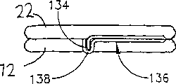
Represent surgical clips in the 3rd device of the present invention at Fig. 3 A-3D, this surgical clips is usually with numeral 130 expressions.The interlude 13 of surgical clips 130 is also made by marmem, and is identical with surgical clips 10, also is the coil that constitutes by two complete annulus 12 and 22.Yet in this device of the present invention, on the ring 22 of surgical clips 130 cutter head 133 is housed, this cutter head is a L shaped arm 132 that points to the center of ring 22, and the tip of arm 132 has blade 134.On the ring 12 tool rest 136 has been installed, tool rest 136 is arms 137 that an end is a U-shaped section 138, and the opening surface of U-shaped section is to the center of ring 12.By certain method, L shaped arm 132 and tool rest 136 are installed in respectively on the ring 22 and 12.Relevant technical specialist can use other rationally cutter heads 133 and tool rest 136 of structure, as long as this structure can play the cutter head and the tool rest function of indication of the present invention.
The interlude 13 of surgical clips 130 is in mecystasis among Fig. 3 A and Fig. 3 B, and ring 12 has separated with 22.Among Fig. 3 C and Fig. 3 D, the interlude of surgical clips is in elastic stage, encircles 12 and 22 mutual extrusion this moment.Among Fig. 3 C, the blade 134 on the cutter head 133 is adjacent with the U-shaped section 138 on the tool rest 136, but does not contact.Respectively along the direction shown in arrow A and the arrow B, artificially pressurization on cutter head 133 and tool rest 136 after the two is stressed, is in contact with one another (shown in Fig. 3 D), and this moment is in the central authorities of the U-shaped section 138 of tool rest, blade 134 and tool rest 136 mutual extrusion.When discharging cutter head 133 with tool rest 136, the two is returned to the position shown in Fig. 3 C.
Fig. 4 A, 4B, 4C and 4D are the legends of surgical clips in the 4th device of the present invention, and this surgical clips is represented with numeral 140.Two circles 142 and 144 are arranged in the surgical clips 140, and the two links to each other by interlude 150.In the surgical clips 140 at least interlude 150 make by marmem, the whole surgery folder can be made with marmem in case of necessity.On the circle 142 and 144 cross bar 146 and 148 are arranged respectively.By chute, cutter head 152 is installed to cross bar 146 central authorities.Cutter head 152 is made of two parts of ring-type 156 and cylinder 158, and groove 159 is arranged on the cylinder 158.Tool rest 162 on the cross bar 148 is cylindrical grooves 154.Flange 160 covers on the groove 154, and is installed in cross bar 148 (shown in Fig. 4 B, 4C, 4D) on the face of cross bar 146.The cylinder 158 of groove 154 and cutter head 152 and flange 160 are in size, identical in shape.
Although cutter head 152 shown in the surgical clips 140 and tool rest 162 have specific shape, relevant expert can also use the cutter head and the tool rest of his shape, as long as can excise the tissue between cutter head and tool rest.
Among Fig. 4 A and Fig. 4 B, the interlude 150 of surgical clips 140 is in mecystasis, its centre circle 142 and opening in 144 minutes.Among Fig. 4 C and Fig. 4 D, interlude 150 is in elastic stage, this hour circle 142 and 144 pressing together tightly, and the cylinder 158 in the cutter head 152 is adjacent with the groove 154 on the cutter head 162.Pressurize along the head 156 of direction shown in the arrow B to cutter head 152 on the cross bar 146, and along direction shown in the arrow C flange on the tool rest 162 160 is pressurizeed, cylinder 158 is pressed in the groove 154, and cylinder 158 is meshing with each other with groove 154 like this.
The cutter head 133 that it is pointed out that surgical clips 130 (shown in Fig. 3 A-3D) can be unloaded down from encircling 22 and 12 respectively with tool rest 136, and in the surgical clips 140, has only cutter head 152 to take off from encircling 142, and tool rest 162 is fixed on the ring 144.
Fig. 4 E is the diagram of the 5th device of the present invention. Surgical clips 170 and 140 has points of resemblance, and interlude 150 is made by marmem, and two circles 142 and 144 are also arranged.Different is, on circle 142 and 144 arm 172 and 174 is arranged respectively, and point and the interior point of circle that these two arms will enclose respectively separately accordingly couple together.Use certain method, arm 172 and 174 is respectively installed on the circle 142 and 144.The end of arm 172 is cutter heads 176, has 178 and the cylinder 180 of trough of belt 181 on the cutter head.The end of arm 174 has been installed tool rest 186, and cylinder 182 and groove 184 are arranged on the tool rest, and the size and shape of cylinder 182 is similar to the cylinder 180 on the tool rest.
Among Fig. 4 E, the interlude 150 of surgical clips 170 is in mecystasis, and its centre circle 142 has separated with 144.When the interlude 150 of surgical clips 170 is in elastic stage (among the figure not show), circle 142 and 144 is by pressing together tightly, and the cylinder 180 in the cutter head 176 is adjacent with the groove 184 of tool rest 186.On arm 172 178 of cutter head 176 and the cylinder 182 of tool rest 186 when being under pressure, the cylinder 180 on the cutter head 176 is pressed in the groove 184, and this moment, cylinder 180 sticked together with the inner surface of groove 184.Fig. 5 A and Fig. 5 B are cutter head and tool rest sketch map, and they may be used in the surgical clips 170 of Fig. 4 E, and wherein tool rest represents that with 200 cutter head is represented with 210.X-shape groove 202 is arranged on the tool rest 200, and groove is corresponding with the blade 212 on the cutter head 210 on the size and shape.When using tool rest 200 in this device of the present invention with cutter head 210, when the interlude of surgical clips was in above-mentioned elastic stage, tool rest 200 was forced into cutter head 210, and blade is entered in the groove 202.
Fig. 5 C is an another one device of the present invention: cutter head 220 and corresponding tool rest 230, they can be used for the surgical clips shown in Figure 1A or Figure 1B.Oval-shaped base 222 is housed on the cutter head 220, has two pin sample blades 224 to stretch out on the base.Oval base 232 has been installed on the tool rest 230, and on size and shape, base 232 should be complementary oriented overhanging flange 234 on this outer base 232 with the base 222 of cutter head 220.Oval groove 236 is arranged on the base 232, and the width of groove is similar to blade 224, and flute length is not less than the distance between the outer end of two blades.When therefore using tool rest 230 with cutter head 220 in device of the present invention, if the interlude of surgical clips is in elastic stage, tool rest 230 is pinched together with cutter head 220, and blade 224 is forced in the groove 236.
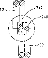
Be the blade of several special combination relations and the example of tool rest among Fig. 5 D, 5E, 5F, 5G, 5H and the 5I, can in Fig. 2-device of the present invention shown in Figure 4, substitute wherein blade and tool rest.Shown in Fig. 5 D, when the marmem in the device is in elastic stage, ring 12 and 22 mutual extrusion.Situation when Fig. 5 D represents respectively that with 5E blade 240 contacts with plane tool rest 242 and 244.Among Fig. 5 F blade 240 and tool rest 248, fluted 250 tops that are used for holding blade 240 on tool rest 248.Fig. 5 G is blade 246 and tool rest 252, and cylinder shape groove 254 is arranged in the tool rest 252, and the width of groove 254 should be able to hold the top 256 of blade 246.When the width of the width that is inserted into 254 li of grooves when blade 246 and groove 254 self is identical, just can not be further toward 254 li propellings of groove.On the tool rest 258 among Fig. 5 H triangular groove 260 is arranged, be used for putting the top of blade 246.Alternative means during Figure 51, wherein there is the blade combination 268 of two blades 262 to replace blade and tool rest, when ring 12 and 22 is pressed against a time-out (shown in Fig. 5 D), these two blades are in contact with one another, blade 262 top 264 along one side 266 propellings wherein of another blade 262.
Fig. 6 A-6D is the surgical clips 300 in the 6th device of the present invention.Two circles are arranged in the surgical clips 300: circle 302 and 304, the two all is connected on the interlude of being made by marmem 306.On circle 302, have not by the cross bar 308 in the center of circle, rotatable cutter head 310 is arranged on the cross bar 308.Cutter head 310 comprises blade 312 and 314, and blade 312 can be by 314 down towards the center of circle direction rotation of circle 302.Tool rest 316 is that the space 320 of pair of parallel cross bar 318, two cross bars 318 is rectangular substantially by the center of circle of circle 304.When cross bar 318 was installed, two cross bar spaces 320 wanted to hold blade 312, and blade 312 can just be put in.Relevant technical specialist can also use any other can with the supporting tool rest of blade 312.
When interlude 306 was in mecystasis, ring 302 and 304 was separated into the position shown in Fig. 6 A.When interlude 306 was in elastic stage, tightly pinched together of circle 302 and 304 quilts was shown in Fig. 6 B-6D.Among Fig. 6 B, constantly along direction shown in the arrow D, to head end 314 pressurizations of cutter head 310, blade 312 can rotate around cross bar 308, thereby moves down.Blade 312 is rotated down and makes cutter head 310 be in position among Fig. 6 C, and this moment, blade 312 can just be inserted in the space 320 of tool rest 316.If desired, biasing or other similar devices can be installed in cutter head 310, blade 312 advances gaps 320 or can automatically revert to it when therefrom pulling out and leaned on last position originally like this.(shown in Fig. 6 D)
Among Fig. 7 A-7D two parts 52 and 54 of the hollow organ 50 that will connect by anastomosis.Hollow organ 50 can be colon or other hollow organs that need coincide.Method among the present invention also can be used for first hollow organ's a part is connected to second hollow organ, is connected to the Weishang as the part with colon.When describing the inventive method, be example with surgical clips 10.Relevant technical specialist when undergoing surgery, can use by method of the present invention with the present invention in relevant any surgical clips, or the surgical clips of top introduction.
In addition, Xiang Guan technical specialist can as the surgical clips among the present invention, be divided into two classes with the marmem device.The marmem that the first kind is used, when cool to room temperature is following, change distortion into and be easy to martensite, when in room temperature, reach austenitic state wholly or in part, when being heated to upper limit phase transition temperature (between between room temperature and body temperature) or when above, marmem changes austenite fully into.In the second class device, marmem at room temperature becomes the martensite of easy deformation, this device generation deformation this moment, and bring into use; When temperature is elevated to room temperature when above, marmem becomes austenite fully.The difference of these two kinds of devices is that marmem is in the easy deformation of which temperature range.Obviously use the device of the second class marmem to use more convenient.All use first kind device in the discussion below the inventive method.
In Fig. 7 A-7D, make marmem section 13 be cooled to lower limit phase transition temperature or following at least, with identical in the prior art, marmem can become martensite, and the interlude 13 of surgical clips is in mecystasis at least.The lower limit phase transition temperature generally all is higher than-273 ℃, and more general than the lower limit phase transition temperature of low 25-30 ℃ of body temperature, 0 ℃ is up and down more satisfactory lower limit phase transition temperature.Artificially will encircle 12 and 22 distances that are separated into actual needs, before injecting organ 50, as long as need, surgical clips 10 can be placed on preservation low temperature under always.
The isolating two parts 52 and 54 of organ are undergone surgery, opening 56 and 58 usefulness staples or surgical thread are sewed up sealed, what use among the figure is surgical thread 72, seals the back and forms closing end 56A and 58A.Two parts 52 and 54 of organ 50 side by side and adjacent, on adjacent wall 60 and 62, puncture forms adjacent hole 64 and 66 places.Selecting hole 64 and 66 size and shape according to actual needs, with convenient in organ two parts 52 and 54 installing ring 12 and 22.To encircle 12 and 22 respectively by hole 64 and 66 and insert, and make ring pass across wall 60 and 62 respectively, surgical clips two parts 52 and 54 of just being inserted into organ have suffered like this.With reference to figure 7A-7D, organ part 52 and 54 was at first all passed through operation among the figure when method of the present invention was described, and sewed up with staple or surgical thread.After inserting surgical clips, without departing from the present invention, relevant technical specialist can oneself determine still two in sutured organ part 52 and 54.
The relative position of two parts 52 of organ 50 and 54 relative position and this two parts and surgical clips 10 must remain unchanged within a certain period of time, the temperature of organ 50 can be elevated to the temperature of the interlude 13 of surgical clips 10 and be not less than its upper limit phase transition temperature (being preferably lower than body temperature) at this moment, and this moment, surgical clips 10 became austenitic state.When the temperature of interlude was elevated to its transition temperature, ring 12 and 22 was constantly drawn close, and oppresses the tissue 68 and 70 on two interannular organ walls 60 and 62 simultaneously, makes the two be pressed De Gengmi.Tissue 68 and 70 is to be respectively that organ walls 60 and 62 is positioned at the tissue on that a part of wall that encircles 12 and 22.Therefore organize 68 to 70 12 similar with surgical clips 10 to 22 size and shapes.
By surgical clips is heated the programming rate that can improve interlude 13, heating means can be any methods that occurred in the prior art.
In case the interlude 13 of surgical clips 10 is warmed up to and is higher than its phase transition temperature, surgical clips is got back to elastic stage, and encircle 12 and 22 mutual extrusion this moment, the relative position of wall 60 and 62 fixed, shown in Fig. 7 C and Fig. 7 D.Simultaneously the blade 48 on the cutter head 20 is extruded in the groove 18, resection organization 68 and 70 portion of tissue, and cut tissue is identical with the size and shape of blade 48.Like this portion of tissue cut after, gastrointestinal tract has just had initial patency.
Use other devices of the present invention, during as the surgical clips 130 among Fig. 3 A-3D, need the people just can make cutter head 133 and tool rest 136 realization shearing functions in the device for applying external force.At this moment, relevant technical specialist can select with additive method of the prior art cutter head and tool rest to be pressurizeed, and has the device of pressurization function etc. such as usefulness.
After tissue 68 and 70 portion of tissue was cut, two parts 52 of organ 50 and 54 only had a passage, i.e. groove 18 on the cross bar 16 of cutter head 20.
Because the wall 60 and 62 of surgical clips 10 extruding organs 50, tissue 68 and 70 is by forcing together tightly, and blood stops to flow herein, makes finally necrosis of tissue 68 and 70.After tissue 68 and 70 necrosis, the 68A of its peripheral organization heals into immediately with 70A, and two parts 52 and 54 of organ 50 just are joined together like this, and organ 50 is still a continuous organ when activity.Along with the necrosis of tissue 68 and 70, this two parts tissue and surgical clips 10 come off from wall 60 and 62, form opening 74, shown in Fig. 7 C.By the normal activity of organ, downright bad tissue 68 with 70 and surgical clips 10 pass through opening 74 and from organ 10, discharge.When if organ 50 is small intestinal, the direction of small intestinal along 52 to 54 wriggling, surgical clips 10 and organize 68 and 70 with the normal organ activity of small intestinal from 54 discharges.
Relevant technical specialist can use the surgical clips 10 (shown in Fig. 7 A-7D) in surgical clips 140 (shown in Fig. 4 A-4D) or the above-mentioned operation of surgical clips 170 (shown in Fig. 4 E) replacement according to actual needs.When using this two kinds of surgical clips of the present invention, after surgical clips (140 or 170) was installed on the organ 50, interlude became above-mentioned elastic stage (martensitic state), and corresponding cutter head (152,176) and tool rest (162,186) form shears engagement.Part tissue between cutter head (152,176) and tool rest (162,186) will be excised by it like this, and the size and the shape of cut tissue and cylinder (158,180) are identical.Organize cut after, gastrointestinal tract has initial patency.
In addition, can use surgical clips 110 (shown in Fig. 2 A and 2B), surgical clips 130 (shown in Fig. 3 A-3D) and surgical clips 300 (as Fig. 6 A-6D) in the above-mentioned operation according to actual needs.During with surgical clips 110, when surgical clips was in elastic stage shown in Fig. 2 A and the 2B, blade 128 was extruded with cross bar 116, formed and sheared engagement, therefore can excise the tissue of the two automatically.Use surgical clips 130 or at 300 o'clock, surgical clips is installed on the organ 50, become above-mentioned elastic stage after, need artificially corresponding cutter head (133,310) and tool rest (136,316) pressurization are realized shearing engagement, excise the tissue of the two.After portion of tissue wherein was cut, gastrointestinal tract had initial patency.Although the size of otch should behind cutting tissue, according to actual needs, still can enlarge otch within the specific limits less than the whole area of tissue 68 and 70.
The size and shape of employed surgical clips directly influences its size and shape that forms the hole on organ in the above-mentioned operation, relevant technical specialist can select the surgical clips of specific dimensions and shape in operation, the size and shape in the hole of formation is corresponded to actual needs.
Need remind relevant technical specialist at this, the present invention is not limited to top description, more than only be to explain the present invention.And scope of the present invention is only by following claims decision.
Claims (8)
1. the surgical clips of being made by marmem to small part comprises following a few part:
First metal wire with closed geometric shape of hollow;
Similar to size to first wire-shaped, second metal wire with closed geometric shape when these two sections metal wire side-by-side alignment, can overlap fully;
Between first and second metal wire, the interlude of making by marmem;
The cutter head that links to each other with first section metal wire;
And link to each other with second section metal wire, can shear the tool rest of engagement with cutter head;
Surgical clips is in first temperature or when above, this first temperature or the above body temperature that is no more than, above-mentioned first and second metal wire is drawn close side by side, above-mentioned marmem is in elastic stage, and in second temperature that is lower than first temperature or when following, this marmem is in mecystasis, therefore make first and second metal wire separate and keep a fixed position, this surgical clips is heated to when being not less than first temperature, above-mentioned first and second metal wire is got back to the above-mentioned state of drawing close side by side, thereby to the two tissue pressurization.
2. surgical clips as claimed in claim 1 further comprises pressure apparatus, makes itself and tool rest shear engagement to cutter head pressurization, and in first temperature or when above, this pressure apparatus pushes this cutter head and tool rest, the two is sheared mesh.
3. surgical clips as claimed in claim 1 further comprises pressure apparatus, to cutter head pressurization it is sheared with tool rest and meshes, and when in first temperature or when above, this pressure apparatus works by external force.
4. surgical clips as claimed in claim 1, closed geometric shape are circular.
5. surgical clips as claimed in claim 1, closed geometric shape are oval.
6. surgical clips as claimed in claim 1, first and second metal wire are continuous coils.
7. surgical clips as claimed in claim 1, first and second metal wire is two sections metal wires independently, the two all has closed geometric shape.
8. surgical clips as claimed in claim 1, cutter head also plays tool rest.
Applications Claiming Priority (2)
| Application Number | Priority Date | Filing Date | Title |
|---|---|---|---|
| IL13670200A IL136702A (en) | 2000-06-12 | 2000-06-12 | Surgical clip |
| IL136702 | 2000-06-12 |
Publications (2)
| Publication Number | Publication Date |
|---|---|
| CN1436060A CN1436060A (en) | 2003-08-13 |
| CN1232228C true CN1232228C (en) | 2005-12-21 |
Family
ID=11074254
Family Applications (1)
| Application Number | Title | Priority Date | Filing Date |
|---|---|---|---|
| CNB018109497A Expired - Fee Related CN1232228C (en) | 2000-06-12 | 2001-06-07 | Surgical clip |
Country Status (6)
| Country | Link |
|---|---|
| EP (1) | EP1301129B1 (en) |
| JP (1) | JP3742386B2 (en) |
| CN (1) | CN1232228C (en) |
| AT (1) | ATE441365T1 (en) |
| CA (1) | CA2411530C (en) |
| DE (1) | DE60139782D1 (en) |
Families Citing this family (13)
| Publication number | Priority date | Publication date | Assignee | Title |
|---|---|---|---|---|
| EP1370204B1 (en) | 2001-02-23 | 2006-08-30 | Refocus Ocular, Inc. | System for making incisions for scleral eye implants |
| US20070088412A1 (en) * | 2005-10-13 | 2007-04-19 | Intelifuse, Inc., A Corporation Of The State Of Delaware | System and device for heating or cooling shape memory surgical devices |
| US8083759B2 (en) | 2007-11-02 | 2011-12-27 | Refocus Ocular, Inc. | Apparatuses and methods for forming incisions in ocular tissue |
| CN102292013B (en) * | 2008-09-05 | 2015-05-27 | 卡内基梅隆大学 | Multi-linked endoscopic device with spherical distal assembly |
| KR101604080B1 (en) | 2009-07-21 | 2016-03-17 | 삼성전자주식회사 | Blood vessel pressing cuff, blood pressure measuring apparatus with the blood vessel pressing cuff, and blood pressure measuring method using the blood pressure measuring apparatus |
| US9687229B2 (en) * | 2010-03-11 | 2017-06-27 | Microkoll Inc. | Apparatus and method for tissue adhesion |
| US8597318B2 (en) | 2011-08-08 | 2013-12-03 | Refocus Group, Inc. | Apparatus and method for forming incisions in ocular tissue |
| WO2017104475A1 (en) | 2015-12-18 | 2017-06-22 | 株式会社カネカ | Connector, medical clip device, and production method for medical clip device |
| US11304698B2 (en) | 2016-07-25 | 2022-04-19 | Virender K. Sharma | Cardiac shunt device and delivery system |
| EP3487418A4 (en) | 2016-07-25 | 2020-04-08 | Virender K. Sharma | Magnetic anastomosis device delivery system |
| US10555725B2 (en) * | 2016-09-29 | 2020-02-11 | Gyrus Acmi, Inc. | Thermal mechanism to prevent reprocessing or reuse of mechanical surgical devices |
| EP3568089B1 (en) | 2017-01-11 | 2021-09-15 | Virender K. Sharma | Cardiac shunt device and delivery system |
| KR20200044799A (en) | 2017-08-23 | 2020-04-29 | 리포쿠스 그룹 인코포레이티드 | Surgical tools and associated devices and methods for forming incisions in ocular tissue with tips that provide visibility |
Family Cites Families (5)
| Publication number | Priority date | Publication date | Assignee | Title |
|---|---|---|---|---|
| US5222963A (en) * | 1991-01-17 | 1993-06-29 | Ethicon, Inc. | Pull-through circular anastomosic intraluminal stapler with absorbable fastener means |
| US5171252A (en) * | 1991-02-05 | 1992-12-15 | Friedland Thomas W | Surgical fastening clip formed of a shape memory alloy, a method of making such a clip and a method of using such a clip |
| US5591173A (en) * | 1994-07-28 | 1997-01-07 | Michael Schifano | Schifano obstetric scissors |
| IL119911A (en) * | 1996-12-25 | 2001-03-19 | Niti Alloys Tech Ltd | Surgical clip |
| IL132635A0 (en) * | 1999-10-28 | 2001-03-19 | Niti Alloys Tech Ltd | Shape memory alloy clip and method of use thereof |
-
2001
- 2001-06-07 CA CA002411530A patent/CA2411530C/en not_active Expired - Fee Related
- 2001-06-07 AT AT01938537T patent/ATE441365T1/en not_active IP Right Cessation
- 2001-06-07 DE DE60139782T patent/DE60139782D1/en not_active Expired - Lifetime
- 2001-06-07 JP JP2002509972A patent/JP3742386B2/en not_active Expired - Fee Related
- 2001-06-07 EP EP01938537A patent/EP1301129B1/en not_active Expired - Lifetime
- 2001-06-07 CN CNB018109497A patent/CN1232228C/en not_active Expired - Fee Related
Also Published As
| Publication number | Publication date |
|---|---|
| CN1436060A (en) | 2003-08-13 |
| JP3742386B2 (en) | 2006-02-01 |
| CA2411530A1 (en) | 2001-12-20 |
| EP1301129B1 (en) | 2009-09-02 |
| JP2004503276A (en) | 2004-02-05 |
| EP1301129A2 (en) | 2003-04-16 |
| CA2411530C (en) | 2009-07-28 |
| DE60139782D1 (en) | 2009-10-15 |
| ATE441365T1 (en) | 2009-09-15 |
| EP1301129A4 (en) | 2008-10-22 |
Similar Documents
| Publication | Publication Date | Title |
|---|---|---|
| CN1232228C (en) | Surgical clip | |
| CN101103933B (en) | Compression anastomosis ring assembly and applicator for use therewith | |
| CN103379865B (en) | Use the Skin sewing needle of rotary needle | |
| CN1726878A (en) | Electroactive polymer-based actuation mechanism for circular stapler | |
| JP3725825B2 (en) | Shape memory alloy clip and method of using the same | |
| CN101873834B (en) | Washer for use with a surgical stapling instrument | |
| CN100337597C (en) | Surgicl apparatus outshoot mechanism having fastener | |
| AU768923B2 (en) | Vascular surgery | |
| CN101044996B (en) | Surgical suturing apparatus | |
| CN1106828C (en) | Percutaneous catheter directed intravascular occulsion devices | |
| CN1647772A (en) | Unfolding anastomosis ring device | |
| CN1655726A (en) | Surgical clip applicator device | |
| CN109381233A (en) | Surgical buttress for surgery suturing apparatus keeps system | |
| US4979954A (en) | Staple suturing method | |
| CN107427300A (en) | Surgical stapling supporter and auxiliary material | |
| US20090302089A1 (en) | Compression assemblies and applicators for use therewith | |
| CN1449724A (en) | Method for attaching hernia mesh | |
| JP5567120B2 (en) | Stapling device | |
| CN1771011A (en) | Anchoring screw device | |
| CN202776430U (en) | Round purse-string forceps capable of suturing purse-string | |
| CN102813538B (en) | Circular purse-string forceps capable of automatically beating purse-strings | |
| CN110300554A (en) | For auxiliary material to be attached to the mixed organization of surgical instruments | |
| CN202776424U (en) | Round purse-string forceps capable of suturing purse-string | |
| CN108113724A (en) | Blood vessel anastomat | |
| RU2712860C2 (en) | Design of surgical staples and extruders for cassettes with staples |
Legal Events
| Date | Code | Title | Description |
|---|---|---|---|
| C06 | Publication | ||
| PB01 | Publication | ||
| C10 | Entry into substantive examination | ||
| SE01 | Entry into force of request for substantive examination | ||
| C14 | Grant of patent or utility model | ||
| GR01 | Patent grant | ||
| C56 | Change in the name or address of the patentee |
Owner name: NITI SURGICAL EQUIPMENT CO., LTD Free format text: FORMER NAME: NITI MEDICAL TECHNOLOGIES LTD. |
|
| CP03 | Change of name, title or address |
Address after: Israel, he Yadehalucimu sub city 42505 Street building 9E 8634 mailbox Patentee after: Niti Surgical Solutions Ltd. Address before: He was the Israeli city of Asia Patentee before: Niti Medical Technologies Ltd. |
|
| C17 | Cessation of patent right | ||
| CF01 | Termination of patent right due to non-payment of annual fee |
Granted publication date: 20051221 Termination date: 20110607 |