JP3737824B2 - Developing device and image forming apparatus - Google Patents
Developing device and image forming apparatus Download PDFInfo
- Publication number
- JP3737824B2 JP3737824B2 JP2005228541A JP2005228541A JP3737824B2 JP 3737824 B2 JP3737824 B2 JP 3737824B2 JP 2005228541 A JP2005228541 A JP 2005228541A JP 2005228541 A JP2005228541 A JP 2005228541A JP 3737824 B2 JP3737824 B2 JP 3737824B2
- Authority
- JP
- Japan
- Prior art keywords
- developer
- toner
- developing device
- receiving port
- conveying
- Prior art date
- Legal status (The legal status is an assumption and is not a legal conclusion. Google has not performed a legal analysis and makes no representation as to the accuracy of the status listed.)
- Active
Links
Images


Description
本発明は、複写機やファクシミリ装置、さらにはプリンタ等の各種の画像形成装置、及び該画像形成装置に適用される現像装置に関するものである。 The present invention relates to various image forming apparatuses such as a copying machine, a facsimile apparatus, and a printer, and a developing device applied to the image forming apparatus.
従来、特許文献1に記載されているような現像装置が知られている。この現像装置は、複写機やファクシミリ装置等の画像形成装置に適用されるものであり、画像形成装置の感光体ドラムにトナーを供給する現像装置本体と、この現像装置本体に着脱自在に装着されるトナー補給用のトナーカートリッジとを備えて構成されている。トナーカートリッジの底部には、開閉可能なトナー排出口が設けられている一方、現像装置本体には、トナー排出口に対応したトナー受入口が設けられ、トナーカートリッジが現像装置本体に装着されることによるトナー排出口の開放でトナーカートリッジ内のトナーが現像装置本体内に形成された所定の循環搬送路に供給されるようになっている。
Conventionally, a developing device as described in
前記循環搬送路は、前記感光体ドラムの軸心と平行に延びる上面開放の溝状に形成されている。かかる循環搬送路は、トナー受入口に対応した往路搬送路と、現像ローラに対応した復路搬送路とからなり、各搬送路の中に、フィン軸周りにスパイラルフィンが設けられてなるスパイラルフィーダがそれぞれ装着され、トナーは、これらスパイラルフィーダのフィーダ軸回りの回転によって往路搬送路と復路搬送路との間を循環搬送されるようになっている。 The circulation conveyance path is formed in a groove shape with an open top surface extending in parallel with the axis of the photosensitive drum. The circulation conveyance path includes an outward conveyance path corresponding to the toner receiving port and a return conveyance path corresponding to the developing roller, and a spiral feeder in which spiral fins are provided around the fin axis is provided in each conveyance path. The toner is respectively mounted, and the toner is circulated and conveyed between the forward conveyance path and the backward conveyance path by rotation of the spiral feeder around the feeder axis.
そして、トナーカートリッジからトナー受入口を介して往路搬送路に受け入れられたトナーは、スパイラルフィーダのフィーダ軸回りの回転で移動させられ、往路搬送路の下流端で復路搬送路に送り込まれる。復路搬送路へ移った現像剤は、スパイラルフィーダの駆動で往路搬送路と逆方向に搬送されつつその中のトナーのみが現像ローラの周面に供給され、残部が下流端で往路搬送路に戻されるようになっている。 Then, the toner received from the toner cartridge through the toner receiving port to the forward conveyance path is moved by rotation around the feeder shaft of the spiral feeder, and is sent to the backward conveyance path at the downstream end of the forward conveyance path. The developer transferred to the return path is transported in the direction opposite to the forward path by the drive of the spiral feeder, and only the toner therein is supplied to the peripheral surface of the developing roller, and the remaining part is returned to the forward path at the downstream end. It is supposed to be.
このような基本構成を有する特許文献1の現像装置においては、往路搬送路に設けられたスパイラルフィーダのトナー受入口より下流側に、搬送能力が局部的に低下するように構成された搬送能力抑制部が設けられている。この搬送能力抑制部は、スパイラルフィンの径寸法を他の部分より小さくすることで搬送能力の低減を実現している。そして、かかる搬送能力抑制部を設けることにより、当該搬送能力抑制部の上流側にトナーの滞留が生じる。このトナーの滞留は、搬送能力抑制部とトナー受入口との間で生じるため、現像装置内にトナーが十分存在する場合には、トナーの滞留がトナー受入口を塞いでトナーカートリッジからのトナーの供給が制限される。これに対し、現像装置内のトナーが消費されてトナー量が減少すると、前記トナーの滞留も減少することになり、これによってトナーが滞留している部分とトナー受入口との間に空間が生じるため、トナーがトナーカートリッジから落下して現像装置内に供給される。現像装置内に十分な量のトナーが供給されると、再びトナーの滞留が生じてトナー受入口を塞いでトナーの供給が制限される。このようにトナーカートリッジから現像装置に供給されるトナーの量は、現像装置内のトナー量によって自動的に調節されることになる。
しかしながら、特許文献1に記載の現像装置にあっては、前記のような搬送能力抑制部を設けてトナーを滞留させ、これによってカートリッジからのトナーの補給を制限するよ
うにしているため、高温環境や、低濃度印字を長時間に亘って続けたときのようなトナーがほとんど消費されない状況で棚吊りが問題になることがあった。
However, in the developing device described in
本発明は、このような状況に鑑みなされたものであり、搬送能力抑制部を備えた現像装置を対象とし、現像剤の循環搬送路におけるトナー受入口近傍に棚吊り現象が発生することを有効に防止することができる現像装置及び画像形成装置を提供することを目的としている。 The present invention has been made in view of such a situation, and is intended for a developing device including a conveyance capability suppressing unit, and is effective in causing a shelf hanging phenomenon in the vicinity of a toner receiving port in a developer circulation conveyance path. It is an object of the present invention to provide a developing device and an image forming apparatus that can be prevented.
請求項1記載の発明は、現像剤を攪拌しながら循環経路を搬送しつつ当該現像剤を像担持体の周面に供給する装置本体部と、この装置本体部内に現像剤を供給する現像剤供給部とを備えて構成され、前記装置本体部には、その上部に設けられた前記現像剤供給部からの現像剤を受け入れる現像剤受入口と、前記循環経路に配置され前記現像剤受入口から受け入れた現像剤を搬送する搬送手段と、前記像担持体に対向配置された現像ローラとが備えられてなる現像装置において、前記循環経路は、前記現像ローラに沿って形成された前方搬送路と、前記現像剤受入口から現像剤の供給を受ける位置に前記前方搬送路と平行に形成された後方搬送路とを備え、前記搬送手段は、軸心回りに回転することにより現像剤を搬送方向に向けて搬送するものであって、前記前方搬送路には前方搬送手段が、前記後方搬送路には後方搬送手段がそれぞれ装着されてなり、前記後方搬送手段には、局部的に搬送能力が抑制されるべく構成された搬送能力抑制部が設けられていると共に、前記現像剤受入口は、前記現像剤の循環経路上であって、前記現像剤受入口を通して現像剤が現像装置内に導入されたときに、前記後方搬送手段の回転によって前記現像剤が上方へ持ち上げられる位置に設けられていることを特徴とする。
The invention according to
かかる構成によれば、現像剤供給部から現像装置本体の現像剤受入口を介して当該現像装置本体内に導入された現像剤は、現像剤受入口が、該現像剤受入口を通して現像剤が現像装置内に導入されたときに、前記後方搬送手段の回転によって前記現像剤が上方へ持ち上げられる位置に配置されていることにより、現像剤受入口の直下で常に搬送手段によって軸心方向に搬送されるため、棚が形成されるような不都合は生じない。 According to such a configuration, the developer introduced into the developing device main body from the developer supply unit via the developer receiving port of the developing device main body has the developer receiving port that passes through the developer receiving port. When the developer is introduced into the developing device, the developer is disposed at a position where the developer is lifted upward by the rotation of the rear conveying means, so that it is always conveyed in the axial direction by the conveying means immediately below the developer receiving port. Therefore, there is no inconvenience that a shelf is formed.
請求項2記載の発明は、請求項1記載の発明において、前記搬送能力抑制部は、前記後方搬送手段にリブ部材が付設されることにより形成されていることを特徴とするものである。 According to a second aspect of the present invention, in the first aspect of the present invention, the conveying capacity suppressing portion is formed by attaching a rib member to the rear conveying means.
かかる構成によれば、後方搬送手段は、搬送能力抑制部においてリブ部材の存在で搬送能力が低下する。 According to such a configuration, the conveyance capability of the rear conveyance unit is reduced due to the presence of the rib member in the conveyance capability suppression unit.
請求項3記載の発明は、請求項1または2記載の発明において、前記搬送能力抑制部は、前記後方搬送手段の径寸法が他の部分の後方搬送手段の径寸法より小さく設定されることにより形成されていることを特徴とするものである。 According to a third aspect of the present invention, in the invention according to the first or second aspect, the conveyance capacity suppressing portion is configured such that the diameter dimension of the rear conveyance means is set smaller than the diameter dimension of the rear conveyance means of the other part. It is characterized by being formed.
かかる構成によれば、後方搬送手段の径寸法が小さいとその分推進力が削がれるため、搬送能力抑制部において後方搬送手段の搬送力は低下する。 According to such a configuration, if the diameter dimension of the rear conveying means is small, the propulsive force is reduced by that amount, so that the conveying force of the rear conveying means is reduced in the conveying capacity suppressing portion.
請求項4記載の発明は、請求項1記載の発明において、前記後方搬送手段が、フィーダ軸と、このフィーダ軸回りに螺旋状で形成されたスパイラルフィンとを備えて構成され、前記スパイラルフィンの前記フィーダ軸回りの一体回転によって現像剤を所定の搬送方向に向けて搬送するスパイラルフィーダからなり、前記現像剤受入口は、前記現像剤の循環経路上であって、前記現像剤受入口を通して現像剤が現像装置内に導入されたときに、前記スパイラルフィンの回転によって前記現像剤が上方へ持ち上げられる位置に設けられていることを特徴とする。 According to a fourth aspect of the present invention, in the first aspect of the invention, the rear conveying means includes a feeder shaft and a spiral fin formed in a spiral shape around the feeder shaft. The developer comprises a spiral feeder that conveys the developer in a predetermined conveyance direction by integral rotation around the feeder shaft, and the developer receiving port is on the developer circulation path and is developed through the developer receiving port. When the developer is introduced into the developing device, the developer is provided at a position where the developer is lifted upward by rotation of the spiral fin.
請求項5記載の画像形成装置は、現像剤を攪拌しながら循環経路を搬送しつつ当該現像剤を像担持体の周面に供給する装置本体部と、この装置本体部内に現像剤を供給する現像剤供給部とを備えて構成され、前記装置本体部には、その上部に設けられた前記現像剤供給部からの現像剤を受け入れる現像剤受入口と、前記循環経路に配置され前記現像剤受入口から受け入れた現像剤を搬送する搬送手段と、前記像担持体に対向配置された現像ローラとが備えられてなり、前記循環経路は、前記現像ローラに沿って形成された前方搬送路と、前記現像剤受入口から現像剤の供給を受ける位置に前記前方搬送路と平行に形成された後方搬送路とを備え、前記搬送手段は、軸心回りに回転することにより現像剤を搬送方向に向けて搬送するものであって、前記前方搬送路には前方搬送手段が、前記後方搬送路には後方搬送手段がそれぞれ装着されてなり、前記後方搬送手段には、局部的に搬送能力が抑制されるべく構成された搬送能力抑制部が設けられていると共に、前記現像剤受入口は、前記現像剤の循環経路上であって、前記現像剤受入口を通して現像剤が現像装置内に導入されたときに、前記後方搬送手段の回転によって前記現像剤が上方へ持ち上げられる位置に設けられている現像装置と、前記搬送手段を駆動する駆動機構とを具備することを特徴とするものである。 The image forming apparatus according to claim 5, an apparatus main body that supplies the developer to the peripheral surface of the image carrier while conveying the circulation path while stirring the developer, and supplies the developer into the apparatus main body. A developer supply unit, and a developer receiving port for receiving the developer from the developer supply unit provided in the upper portion of the apparatus main body, and the developer disposed in the circulation path. A conveying unit configured to convey the developer received from the receiving port; and a developing roller disposed to face the image carrier. The circulation path includes a front conveying path formed along the developing roller; A rear conveyance path formed in parallel to the front conveyance path at a position where the developer is supplied from the developer receiving port, and the conveyance means rotates in the conveyance direction by rotating around the axis. To be transported towards The front conveying path is equipped with a front conveying means, and the rear conveying path is equipped with a rear conveying means, and the rear conveying means is configured to locally suppress the conveying capacity. The developer receiving port is provided on the circulation path of the developer, and when the developer is introduced into the developing device through the developer receiving port, the rear conveying unit is provided The developing device is provided at a position where the developer is lifted upward by the rotation, and a drive mechanism for driving the conveying means.
請求項1記載の発明によれば、現像剤供給部から現像装置本体の現像剤受入口を介して当該現像装置本体内に導入された現像剤は、現像剤受入口が、該現像剤受入口を通して現像剤が現像装置内に導入されたときに、前記後方搬送手段の回転によって前記現像剤が上方へ持ち上げられる位置に配置されていることにより、現像剤受入口の直下で常に搬送手段によって軸心方向に搬送されるため、棚が形成されるような不都合の発生を確実に防止することができる。 According to the first aspect of the present invention, the developer introduced into the developing device main body from the developer supply unit via the developer receiving port of the developing device main body has the developer receiving port. When the developer is introduced into the developing device through the position , the developer is always lifted up by the rotation of the rear conveying means, so that the shaft is always provided by the conveying means immediately below the developer receiving port. Since it is conveyed in the direction of the heart, it is possible to reliably prevent the occurrence of inconvenience such as the formation of a shelf.
請求項2記載の発明によれば、搬送能力抑制部は、後方搬送手段にリブ部材が付設されることにより形成されているため、簡単な構造でありながら後方搬送手段の搬送能力を確実に低下させることが可能になり、装置コストの低減化に貢献することができる。 According to the second aspect of the present invention, since the conveyance capability suppressing portion is formed by attaching the rib member to the rear conveyance unit, the conveyance capability of the rear conveyance unit is reliably reduced while having a simple structure. This can contribute to the reduction of the device cost.
請求項3記載の発明によれば、搬送能力抑制部は、後方搬送手段の径寸法が他の部分の後方搬送手段の径寸法より小さく設定されることにより形成されているため、後方搬送手段の径寸法が小さい分推進力が削がれ、これによって搬送能力抑制部の搬送力を確実に低下させることができる。 According to the third aspect of the present invention, the conveyance capacity suppressing portion is formed by setting the diameter dimension of the rear conveyance means to be smaller than the diameter dimension of the rear conveyance means of the other part. The propulsive force is reduced by the smaller diameter dimension, which can reliably reduce the conveying force of the conveying capacity suppressing unit.
請求項4記載の発明によれば、現像剤受入口が、スパイラルフィンの回転によって前記現像剤が上方へ持ち上げられる位置に設けられているので、現像剤が棚吊り状態になり難くすることができる。 According to the fourth aspect of the present invention, since the developer receiving port is provided at a position where the developer is lifted upward by the rotation of the spiral fin, the developer can hardly be suspended. .
請求項5記載の発明によれば、棚吊り現象が発生することを有効に防止することができる現像装置が搭載された画像形成装置を提供できるようになる。 According to the fifth aspect of the present invention, it is possible to provide an image forming apparatus equipped with a developing device capable of effectively preventing the shelf hanging phenomenon.
図1は、本発明に係る現像装置の一実施形態を示す分解斜視図である。また、図2および図3は、図1に示す現像装置の側面視の断面図であり、図2は、トナーカートリッジが現像装置本体から外された状態、図3は、トナーカートリッジが現像装置本体に装着された状態をそれぞれ示している。また、図4は、現像装置本体のハウジングの平面視の断面図である。なお、これらの図において、X−X方向を幅方向、Y−Y方向を前後方向といい、特に−X方向を左方、+X方向を右方、−Y方向を前方、+Y方向を後方という。 FIG. 1 is an exploded perspective view showing an embodiment of a developing device according to the present invention. 2 and 3 are side sectional views of the developing device shown in FIG. 1, FIG. 2 shows a state in which the toner cartridge is removed from the developing device main body, and FIG. 3 shows the toner cartridge in the developing device main body. Each of the attached states is shown. FIG. 4 is a cross-sectional view in plan view of the housing of the developing device main body. In these drawings, the XX direction is referred to as the width direction, and the YY direction is referred to as the front-rear direction. In particular, the -X direction is referred to as the left, the + X direction is referred to as the right, the -Y direction is referred to as the front, and the + Y direction is referred to as the rear. .
まず、図1に示すように、現像装置10は、トナーを感光体ドラム(像担持体)D(図2、図3)の周面に供給するべく当該感光体ドラムDに隣設された現像装置本体(装置本体部)20と、この現像装置本体20に着脱自在に装着されてトナーを補給するトナーカートリッジ(現像剤供給部)70とを備えた基本構成を有している。
First, as shown in FIG. 1, the developing
前記現像装置本体20は、内部にトナー(現像剤)を循環移動させる循環搬送路(循環経路)301を備えたハウジング30と、このハウジング30の上面開口を閉止する蓋体40と、この蓋体40に形成されたトナー受入口(現像剤受入口)44を開閉するべく当該蓋体40に取り付けられた蓋体側シャッタ部材50とを備えて構成され、蓋体側シャッタ部材50の装着された蓋体40がハウジング30に固定されることによって現像装置本体20が形成されるようになっている。
The developing
前記ハウジング30は、前方に向って先下がりに形状設定された略菱形を呈する幅方向一対の側板31と、各側板31の前縁部間に架設された前方板32と、同後縁部間に架設された後方板33と、各側板31の下縁部および後方板33の下縁部に架設された搬送部35(図2)とを備えている。そして、各側板31、前方板32、後方板33および底板35によって囲繞された空間にトナーを循環搬送する循環搬送路301が形成されているとともに、この循環搬送路301に一対のスパイラルフィーダ(搬送手段)60が装着されている。
The
前記循環搬送路301は、前方に形成された幅方向に長尺の前方搬送路302と、この前方搬送路302の後方に当該前方搬送路302と平行に形成された後方搬送路303とからなっているとともに、前記スパイラルフィーダ60は、前方搬送路302に装着される前方スパイラルフィーダ61と、後方搬送路303に装着される後方スパイラルフィーダ62とからなっている。循環搬送路301の底部35には、図2に示すように、前方搬送路302に対応した断面視で円弧状の前方搬送路側底板351と、後方搬送路303に対応した断面視で円弧状の後方搬送路側底板352とが設けられている。
The
前記前後のスパイラルフィーダ61,62は、循環搬送路301内で一対の側板31間に架設されたフィーダ軸63と、このフィーダ軸63回りに螺旋状で形成されたスパイラルフィン64とを備えて構成され、スパイラルフィン64のフィーダ軸63回りの一体回転によって循環搬送路301内に装填されているトナーを循環搬送させ得るようになっている。
The front and rear
そして、本実施形態においては、前方スパイラルフィーダ61のスパイラルフィン64は、フィーダ軸63の端面から見て反時計方向に回ることにより前進する、いわゆる左回り螺旋が形成されているのに対し、後方スパイラルフィーダ62のスパイラルフィン64は、フィーダ軸63の端面から見て時計方向に回ることにより前進する、いわゆる右回り螺旋が形成されている。したがって、前方スパイラルフィーダ61がフィーダ軸63回りに反時計方向に回転すると、前方搬送路302内に位置したトナーは左方へ搬送されるのに対し、後方スパイラルフィーダ62がフィーダ軸63回りに反時計方向に回転すると、
後方搬送路303内のトナーは右方に向けて搬送されることになる。
In the present embodiment, the
The toner in the
また、前方および後方搬送路302,303間には、仕切り壁34が設けられているとともに、当該仕切り壁34には、その左端部および右端部が切り欠かれることによって形成した、前方および後方搬送路302,303間をつなぐ連絡通路304が設けられている。したがって、前方および後方スパイラルフィーダ61,62がそれぞれフィーダ軸63回りに反時計方向に回転することにより、循環搬送路301内のトナーは、左右の連絡通路304を介して前方搬送路302と後方搬送路303との間で反時計方向に向けて循環搬送される。
Further, a
そして、前方搬送路302より前方位置における一対の側板31間には、図2および図3に示すように、ローラ軸65が架設されているとともに、このローラ軸65回りに一体回転可能に現像ローラ66が軸支されている。また、前方搬送路302と現像ローラ66が設けられている部分とは幅方向の略全長に亘って連通状態とされているとともに、現像ローラ66は、その周面が前方の感光体ドラムDの周面と対向するように設置位置が設定されている。したがって、前方搬送路302を搬送されつつあるトナーは、現像ローラ66を介して感光体ドラムDの周面に供給され、これによって感光体ドラムDの周面にトナー像が形成されることになる。
As shown in FIGS. 2 and 3, a
前記蓋体40は、平板状の蓋体本体41と、この蓋体本体41の前後方向の中央位置に立設された幅方向に延びる立設壁42とを備えている。前記蓋体本体41は、平面寸法がハウジング30の上面開口より若干大きめに設定され、これによって蓋体本体41がハウジング30の上面に被せられた状態で、循環搬送路301の上面が閉止されるようになっている。かかる蓋体本体41における立設壁42より後方位置の幅方向略中央部には、前記蓋体側シャッタ部材50を装着するためのシャッタ装着部43が設けられている。このシャッタ装着部43には、トナーカートリッジ70からのトナーをハウジング30内に装填するためのトナー受入口44が設けられている。蓋体側シャッタ部材50は、このトナー受入口44を開閉するためものである。
The
前記トナー受入口44は、図2および図3に示すように、蓋体40がハウジング30に装着された状態で、後方スパイラルフィーダ62の回転方向の上流側に対向するように設けられている。本実施形態においては、後方スパイラルフィーダ62は、フィーダ軸63回りに反時計方向に回転するようになっているため、回転方向の上流側にトナー受入口44が設けられている。
As shown in FIGS. 2 and 3, the
したがって、トナー受入口44を通って後方搬送路303内に供給されたトナーは、まず、スパイラルフィン64の回転に案内されて当該スパイラルフィン64の上部を後方から前方に移動することになる。その後、トナーは、スパイラルフィン64のフィーダ軸63回りの反時計方向に向かう回転に誘導されて右方(図2および図3の紙面の裏側)に向けて搬送されるようになっている。
Therefore, the toner supplied into the
前記蓋体側シャッタ部材50は、蓋体40のトナー受入口44に対応したシャッタ板51と、このシャッタ板51の幅方向両側部に設けられた前後方向に延びる一対の突条52とを備えて構成されている。前記シャッタ板51は、トナー受入口44を塞ぐのに十分な平面寸法を有している。また前記一対の突条52の後端縁には、後方に向って先下がりに設定された傾斜面53がそれぞれ設けられている。これらの傾斜面53は、トナーカートリッジ70を現像装置本体20に装着したときに、当該トナーカートリッジ70の底部との干渉で蓋体側シャッタ部材50を前方へ移動させるためのものであり、これによるシャッタ板51の前方への移動でトナー受入口44が開放されるようになっている。
The lid-
因みに、トナーカートリッジ70は、現像装置本体20に装着された状態で、図3に示すように、付勢手段であるコイルスプリング45によって後方に向けて押圧され、これによって現像装置本体20に対する装着状態が安定するようになされている。
Incidentally, as shown in FIG. 3, the
かかる蓋体側シャッタ部材50は、図略のコイルスプリング等の付勢手段の付勢力で後方に向けて付勢されている。したがって、トナーカートリッジ70が現像装置本体20に装着されていない状態では、トナー受入口44がシャッタ板51によって閉止された状態になる一方、トナーカートリッジ70が現像装置本体20に装着されると、蓋体側シャッタ部材50は、傾斜面53がトナーカートリッジ70の低部に押圧されることにより付勢手段の付勢力に抗して前進し、これによってトナー受入口44が開放されるようになっている。
The lid-
前記トナーカートリッジ70は、図1に示すように、トナーが装填されるカートリッジ本体71と、このカートリッジ本体71の上面開口を閉止するカバー体78とを備えて構成されている。カートリッジ本体71の上縁部には、外方に向って突設された環状の本体側フランジ部710が設けられている一方、カバー体78には、前記本体側フランジ部710に対応した蓋体側フランジ部780が設けられ、カートリッジ本体71内にトナーが装填された状態で各フランジ部710,780同士が溶着処理等で固定されることにより、内部にトナーの装填されたトナーカートリッジ70が仕上がるようになっている。
As shown in FIG. 1, the
前記カートリッジ本体71は、左右幅寸法が現像装置本体20のハウジング30における一対の側板31間の内寸法より僅かに短めに設定されているとともに、前後幅寸法がハウジング30の後方板33と、蓋体40の立設壁42との間の内寸法より僅かに短めに設定され、これによってハウジング30における前記循環搬送路301より上方であって、側板31、後方板33および立設壁42に囲繞されたカートリッジ装着空間305に対して着脱可能になっている。
The
かかるカートリッジ本体71は、図2に示すように、側面視で底板72が二こぶ状に形成されている。すなわち、かかる底板72は、前記蓋体40のシャッタ装着部43と対応した前方円弧底板721と、この前方円弧底板721の後方に形成された後方円弧底板722とを備えている。
As shown in FIG. 2, the cartridge
前方円弧底板721の最下位置には、前記蓋体40のトナー受入口44と対向するように穿設されたトナー排出口73が設けられ、トナーカートリッジ70がハウジング30に装着された状態(図3)で、トナーカートリッジ70内のトナーがこのトナー排出口73および蓋体40のトナー受入口44を介してハウジング30内に供給されるようになっている。
At the lowermost position of the front
前記後方円弧底板722の上方には、当該後方円弧底板722の曲率中心位置に沿うように一対の側板74間に架設された攪拌部材75が設けられている。この攪拌部材75は、前記一対の側板74間で軸心回りに回転可能に架設される軸部材751と、この軸部材751の周面から径方向に突設された攪拌フィン752とからなっている。攪拌フィン752は、合成樹脂製のシート体から構成され、攪拌部材75が図略の駆動モータの駆動で軸心回りに図3における時計方向に回転することにより、後方円弧底板722上のトナーを掻き取って前方円弧底板721へ向けて供給するようになっている。
Above the rear
前記前方円弧底板721の上方には、当該前方円弧底板721の曲率中心位置に沿うように一対の側板74間に架設されたスパイラルロッド76と、このスパイラルロッド76に外嵌されたカートリッジ側シャッタ部材77とが設けられている。スパイラルロッド76は、前記攪拌部材75と同期回転することにより、後方円弧底板722上から前方円弧
底板721上へ送り込まれたトナーをトナー排出口73へ向けて搬送するようにスパイラルの設定方向および回転方向が設定されている。
Above the front
前記カートリッジ側シャッタ部材77は、スパイラルロッド76回りに回転可能に外嵌される筒体によって形成され、前記トナー排出口73を閉止する円弧シャッタ部771と、この円弧シャッタ部771の反時計方向側の縁部に隣設された前記トナー排出口73に対応する左右幅方向(図2の紙面に直交する方向)に長尺の長孔772と、この長孔772に反時計方向で隣設された円弧壁773とを備えて構成されている。円弧シャッタ部771と円弧壁773との周方向における対向縁部間には、攪拌部材75によって送り込まれたトナーをスパイラルロッド76へ供給するための開口部774が形成されている。
The cartridge-
かかるカートリッジ側シャッタ部材77は、図2に示すトナー排出口閉止姿勢と、図3に示すトナー排出口開放姿勢との間で姿勢変更可能になっている一方、前記ハウジング30の右側の側板31には、カートリッジ側シャッタ部材77に対して姿勢変更操作を行うための姿勢変更操作部材80が設けられている。
The cartridge-
この姿勢変更操作部材80は、図2に示すように、カートリッジ装着空間305の円弧底板36の略曲率中心回りに回動自在に側板31の外側に装着された操作円板81と、この操作円板81の回動中心回りの回動にリンクしてカートリッジ側シャッタ部材77をトナー排出口閉止姿勢と同開放姿勢との間で姿勢変更させる姿勢変更部材82とを備えて構成されている。前記操作円板81には、外周面から径方向の外方に向って突設された操作杆811が設けられているとともに、この操作杆811と略対向した周面に噛合歯812が設けられている。
As shown in FIG. 2, the posture changing
前記姿勢変更部材82は、下部が半円状に形成された半円部821と、この半円部821の上部に一体に形成されたが矩形状の矩形部822とからなっている。かかる姿勢変更部材82は、ハウジング30の右方の側板31の内側に、半円部821の曲率中心位置が前記スパイラルロッド76と同心になるように図略の軸回りに回動自在に軸支されることによってハウジング30に取り付けられている。
The
このような姿勢変更部材82には、その内面側に、矩形部822における半円部821と対向した縁部から半円部821の曲率中心位置へ向って凹設された、前記スパイラルロッド76の右端部が嵌め込まれる嵌込み溝83が設けられている。この嵌込み溝83における前記曲率中心位置には、曲率中心から径方向の外方に向かって突設された係止突起831が設けられている一方、カートリッジ側シャッタ部材77の右端部には、前記係止突起831に外嵌する図略の係止溝が設けられている。
In such a
そして、姿勢変更部材82が、図2に示すように、起立姿勢に姿勢設定された状態で、カートリッジ側シャッタ部材77がトナー排出口閉止姿勢に姿勢設定された状態のトナーカートリッジ70をハウジング30のカートリッジ装着空間305に装着することにより、係止溝が係止突起831に外嵌した状態になる。
As shown in FIG. 2, the
この状態で操作杆811の操作により操作円板81を反時計方向に回動すれば(図2において二点鎖線で示す操作杆811参照)、この回動は、噛合歯812を介して姿勢変更部材82に伝達され、これによる姿勢変更部材82の曲率中心回りの時計方向に向かう回動で当該姿勢変更部材82は、図2に二点鎖線で示すように横臥姿勢に姿勢変更し、これによる係止突起831を介したカートリッジ側シャッタ部材77の時計方向への回動で、当該カートリッジ側シャッタ部材77は、図3に示すように、長孔772がトナー排出口73と対向したトナー排出口開放姿勢に姿勢設定されることになる。
In this state, if the
そして、本発明においては、図4に示すように、後方スパイラルフィーダ62には、トナー受入口44より下流側に搬送能力抑制部67が設けられている。図5は、搬送能力抑制部67の一実施形態を示す斜視図である。図5に示すように、搬送能力抑制部67は、スパイラルフィン64の周縁部にフィーダ軸63と平行に付設された周方向複数本の抑制ロッド(リブ部材)671を備えて構成されている。本実施形態においては、抑制ロッド671は、周方向に等ピッチで4本が設けられているが、抑制ロッド671が4本であることに限定されるものではなく、3本以下であってもよいし、5本以上であってもよい。
In the present invention, as shown in FIG. 4, the
かかる搬送能力抑制部67が後方スパイラルフィーダ62におけるトナー受入口44より下流側に設けられることにより、フィーダ軸63の軸心回りの反時計方向に向かう回転によってスパイラルフィン64により下流側(図5の右方)へ搬送されるトナーは、搬送能力抑制部67に到達した時点で抑制ロッド671に妨害されて前進するのが困難になるため、搬送能力抑制部67の上流側で滞留するようになる。したがって、トナーが補給されてトナー量が増えると、この滞留したトナーがトナー受入口44を塞ぐように作用し、それ以上のトナーの補給を抑制する。トナーが消費され、滞留したトナーが少なくなると、トナーが滞留している部分とトナー受入口44との間に隙間ができ、この隙間にトナーが補給される。
By providing such a conveyance
以上詳述したように、本発明の現像装置10は、トナーを攪拌しながら循環搬送路301を搬送しつつトナーを感光体ドラムDの周面に供給する現像装置本体20と、この現像装置本体20内にトナーを供給するべく当該現像装置本体20に着脱自在に装着されるトナーカートリッジ70とを備えて構成され、トナーカートリッジ70にはその前方円弧底板721にトナーを排出するトナー排出口73が設けられている一方、現像装置本体20にはその上部にトナー排出口73と対応し、かつ、循環搬送路301に続くトナー受入口44が設けられ、循環搬送路301には、トナー受入口44から受け入れたトナーを含むトナーを搬送する搬送手段としての後方スパイラルフィーダ62が設けられ、この後方スパイラルフィーダ62は、トナー受入口44の下流側で局部的に搬送能力が低下するように構成された搬送能力抑制部67を有してなるものであり、トナー受入口44は、後方スパイラルフィーダ62の回転方向の上流側に設けられているため、トナーカートリッジ70からトナー排出口73および現像装置本体のトナー受入口44を介して当該現像装置本体内に導入されたトナーは、スパイラルフィン64によって上方へ向けて持ち上げられるようになる。また、後方スパイラルフィーダ62の回転方向の上流側にトナー受入口44が設けられているため、滞留したトナーは、上流側の壁(後方板33)を介して軸方向に搬送されることから、棚吊り状態になり難い。
As described above in detail, the developing
これに対し、トナー受入口44がスパイラルフィーダ60の回転方向の下流側に設けられている場合(従来技術)には、滞留したトナーの動きが少ないため、トナーが押し固められるような状態になり、トナーの流動性が悪くなる高温環境や、トナーの消費が極端に少ない低濃度印字を長時間に亘って続けた場合、棚吊り状態になり易いという問題があったのである。
On the other hand, when the
そして、上記の実施形態においては、搬送能力抑制部67は、スパイラルフィン64に抑制ロッド671が付設されることにより形成されているため、簡単な構造でありながらスパイラルフィーダ60の搬送能力を確実に低下させることが可能になり、装置コストの低減化に貢献することができる。
In the above-described embodiment, since the conveyance
本発明は、上記の実施形態に限定されるものではなく、以下の内容をも包含するものである。 The present invention is not limited to the above embodiment, and includes the following contents.
(1)上記の実施形態においては、前方スパイラルフィーダ61としてスパイラルフィ
ン64が左回り螺旋のものを採用する一方、後方スパイラルフィーダ62としてスパイラルフィン64が右回り螺旋のものを採用し、これによって前方および後方スパイラルフィーダ61,62の双方を同一方向に回転させることにより、トナーが循環搬送路301に沿って循環搬送されるようにしているが、こうする代わりに前方および後方スパイラルフィーダ61,62の各スパイラルフィン64を同一方向の螺旋とした上でこれらの回転方向を逆にしてもよい。こうすることによって循環搬送路301内でトナーを循環搬送することができる。
(1) In the above embodiment, a
(2)上記の実施形態においては、後方スパイラルフィーダ62の回転方向が図3における反時計方向であることからトナー受入口44が後方搬送路303の後方側に設けられているが、本発明は、トナー受入口44が後方搬送路303の後方側に設けられることに限定されるものではなく、後方スパイラルフィーダ62の回転方向が時計方向の場合は、トナー受入口44は、後方搬送路303の前方側に設けられる。こうすることによってトナー受入口44は、後方スパイラルフィーダ62の回転方向の上流側に設けられることになる。
(2) In the above embodiment, since the rotation direction of the
(3)上記の実施形態においては、搬送能力抑制部67は、スパイラルフィン64の周縁部にフィーダ軸63と平行に抑制ロッド671を付設することにより形成されているが、本発明は、搬送能力抑制部67がスパイラルフィン64に抑制ロッド671が付設されることによって形成されるものに限定されるものではなく、たとえば、スパイラルフィン64の径寸法をこの部分だけ他より小さくするなど、トナーの搬送に障害を与えるようなものであれば、各種の方策を採用することが可能である。
(3) In the above embodiment, the conveyance
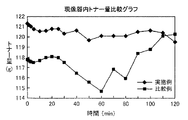
本発明の効果を確認するべく、加速度試験のために印字率が0%のランニング処理(全く印字されない状態で用紙を感光体ドラムDに通す処理)を2時間継続し、これによって現像装置本体20内におけるトナーの循環状態を安定させた後、印字密度5%の画像濃度で用紙に転写処理を施すランニング処理を2時間継続し、この2時間の間で現像装置本体20内のトナー量の推移を測定する効果確認試験を実施した。この試験で使用した画像形成装置の機種は、京セラミタ株式会社製の「FS−1010」であった。
In order to confirm the effect of the present invention, for the acceleration test, a running process with a printing rate of 0% (a process in which the paper is passed through the photosensitive drum D in a state where no printing is performed) is continued for 2 hours. After the toner circulation state is stabilized, a running process for transferring the sheet to the paper with an image density of 5% is continued for 2 hours, and the amount of toner in the developing device
また、比較例として、後方スパイラルフィーダ62の螺旋の向きを逆向きに形成し、フィーダ軸63回りの回転方向を実施例と逆(時計方向に回転)にした場合(すなわちトナー受入口44が後方スパイラルフィーダ62の回転方向の下流側になるように設定した場合)のトナー量の推移を測定した。
Further, as a comparative example, when the spiral direction of the
試験結果は、図6および図7に示すとおりである。図6は、横軸に時間(min)を設定するとともに、縦軸に現像装置本体20内に供給された累積トナー量(g)を示した推移グラフであり、図7は、図6の推移グラフを基に計算した現像装置本体20内のトナー量(g)の推移を示すグラフである。因みに、図6および図7において、「◆」は実施例であり、「■」は比較例である。また、図6における点線は、トナーが計算どおりに供給された場合を想定したトナー消費量累積直線である。
The test results are as shown in FIGS. FIG. 6 is a transition graph in which time (min) is set on the horizontal axis and the cumulative toner amount (g) supplied into the developing
図6および図7に示すように、実施例においては、現像装置本体20内のトナー量は略一定で推移し、これによってトナーが現像装置10から感光体ドラムDに対して安定した状態で供給されているのが判る。これに対し比較例の場合、現像装置本体20内のトナーの量は大きく変動している。これは、後方スパイラルフィーダ62内におけるトナー受入口44直下近傍でトナーの棚吊り現象が発生したことに起因していると考えられる。
As shown in FIGS. 6 and 7, in the embodiment, the amount of toner in the developing device
10 現像装置 20 現像装置本体(装置本体部)
30 ハウジング 301 循環搬送路(循環経路)
302 前方搬送路 303 後方搬送路
304 連絡通路 305 カートリッジ装着空間
31 側板 32 前方板
33 後方板 34 仕切り壁
40 蓋体 41 蓋体本体
42 立設壁 43 シャッタ装着部
44 トナー受入口(現像剤受入口)
45 コイルスプリング 50 蓋体側シャッタ部材
51 シャッタ板 52 突条
53 傾斜面 60 スパイラルフィーダ(搬送手段)
61 前方スパイラルフィーダ 62 後方スパイラルフィーダ
63 フィーダ軸 64 スパイラルフィン
65 ローラ軸 66 現像ローラ
67 搬送能力抑制部 671 抑制ロッド(リブ部材)
70 トナーカートリッジ(現像剤供給部)
71 カートリッジ本体 710 本体側フランジ部
72 底板 721 前方円弧底板
722 後方円弧底板 73 トナー排出口
74 側板 75 攪拌部材
751 軸部材 752 攪拌フィン
76 スパイラルロッド 77 カートリッジ側シャッタ部材
771 円弧シャッタ部 772 長孔
773 円弧壁 774 開口部
78 カバー体 780 蓋体側フランジ部
80 姿勢変更操作部材 81 操作円板
811 操作杆 812 噛合歯
82 姿勢変更部材 821 半円部
822 矩形部 83 嵌込み溝
831 係止突起 D 感光体ドラム(像担持体)
10 Developing
30
302
45
61
70 Toner cartridge (developer supply unit)
71
Claims (5)
前記装置本体部には、その上部に設けられた前記現像剤供給部からの現像剤を受け入れる現像剤受入口と、前記循環経路に配置され前記現像剤受入口から受け入れた現像剤を搬送する搬送手段と、前記像担持体に対向配置された現像ローラとが備えられてなる現像装置において、
前記循環経路は、前記現像ローラに沿って形成された前方搬送路と、前記現像剤受入口から現像剤の供給を受ける位置に前記前方搬送路と平行に形成された後方搬送路とを備え、
前記搬送手段は、軸心回りに回転することにより現像剤を搬送方向に向けて搬送するものであって、前記前方搬送路には前方搬送手段が、前記後方搬送路には後方搬送手段がそれぞれ装着されてなり、
前記後方搬送手段には、局部的に搬送能力が抑制されるべく構成された搬送能力抑制部が設けられていると共に、
前記現像剤受入口は、前記現像剤の循環経路上であって、前記現像剤受入口を通して現像剤が現像装置内に導入されたときに、前記後方搬送手段の回転によって前記現像剤が上方へ持ち上げられる位置に設けられていることを特徴とする現像装置。 An apparatus main body that supplies the developer to the circumferential surface of the image carrier while conveying the circulation path while stirring the developer, and a developer supply that supplies the developer into the apparatus main body. ,
In the apparatus main body, a developer receiving port that receives developer from the developer supply unit provided on the upper portion of the apparatus main body, and a transport that transports the developer that is arranged in the circulation path and is received from the developer receiving port And a developing device comprising a developing roller disposed opposite to the image carrier,
The circulation path includes a front conveyance path formed along the developing roller, and a rear conveyance path formed in parallel with the front conveyance path at a position where the developer is supplied from the developer receiving port.
The conveying means conveys the developer in the conveying direction by rotating around an axis, and a front conveying means is provided in the front conveying path, and a rear conveying means is provided in the rear conveying path, respectively. Being attached,
The rear conveying means is provided with a conveying capacity suppressing unit configured to suppress the conveying capacity locally,
The developer receiving port is on the developer circulation path, and when the developer is introduced into the developing device through the developer receiving port, the developer is moved upward by the rotation of the rear conveying unit. A developing device, wherein the developing device is provided at a lifted position .
前記現像剤受入口は、前記現像剤の循環経路上であって、前記現像剤受入口を通して現像剤が現像装置内に導入されたときに、前記スパイラルフィンの回転によって前記現像剤が上方へ持ち上げられる位置に設けられていることを特徴とする請求項1記載の現像装置。 The rear conveying means includes a feeder shaft and a spiral fin formed in a spiral shape around the feeder shaft, and the developer is rotated in a predetermined conveying direction by integral rotation of the spiral fin around the feeder shaft. It consists of a spiral feeder that conveys toward the
The developer receiving port is on the developer circulation path, and when the developer is introduced into the developing device through the developer receiving port, the developer is lifted upward by the rotation of the spiral fin. The developing device according to claim 1, wherein the developing device is provided at a predetermined position.
前記搬送手段を駆動する駆動機構と
を具備することを特徴とする画像形成装置。 An apparatus main body that supplies the developer to the circumferential surface of the image carrier while conveying the circulation path while stirring the developer, and a developer supply that supplies the developer into the apparatus main body. The apparatus main body is transported with a developer receiving port for receiving the developer from the developer supply unit provided on the apparatus main body, and a developer disposed in the circulation path and received from the developer receiving port. And a developing roller disposed opposite to the image carrier. The circulation path includes a front conveying path formed along the developing roller and a developer receiving port from the developer receiving port. A rear conveyance path formed in parallel with the front conveyance path at a position to receive supply, and the conveyance means conveys the developer in the conveyance direction by rotating around an axis, Forward transport in the front transport path A stage is provided with a rear conveying means on the rear conveying path, respectively, and the rear conveying means is provided with a conveying capacity suppressing portion configured to locally suppress the conveying capacity, The developer receiving port is on the developer circulation path, and when the developer is introduced into the developing device through the developer receiving port, the developer is moved upward by the rotation of the rear conveying unit. A developing device provided at a position to be lifted ;
An image forming apparatus comprising: a driving mechanism that drives the conveying unit.
Priority Applications (1)
| Application Number | Priority Date | Filing Date | Title |
|---|---|---|---|
| JP2005228541A JP3737824B2 (en) | 2005-08-05 | 2005-08-05 | Developing device and image forming apparatus |
Applications Claiming Priority (1)
| Application Number | Priority Date | Filing Date | Title |
|---|---|---|---|
| JP2005228541A JP3737824B2 (en) | 2005-08-05 | 2005-08-05 | Developing device and image forming apparatus |
Related Parent Applications (1)
| Application Number | Title | Priority Date | Filing Date |
|---|---|---|---|
| JP2004162198A Division JP3739004B2 (en) | 2004-05-31 | 2004-05-31 | Developing device and image forming apparatus |
Publications (3)
| Publication Number | Publication Date |
|---|---|
| JP2005346116A JP2005346116A (en) | 2005-12-15 |
| JP3737824B2 true JP3737824B2 (en) | 2006-01-25 |
| JP2005346116A5 JP2005346116A5 (en) | 2006-02-02 |
Family
ID=35498478
Family Applications (1)
| Application Number | Title | Priority Date | Filing Date |
|---|---|---|---|
| JP2005228541A Active JP3737824B2 (en) | 2005-08-05 | 2005-08-05 | Developing device and image forming apparatus |
Country Status (1)
| Country | Link |
|---|---|
| JP (1) | JP3737824B2 (en) |
Cited By (1)
| Publication number | Priority date | Publication date | Assignee | Title |
|---|---|---|---|---|
| JP2018031844A (en) * | 2016-08-23 | 2018-03-01 | 京セラドキュメントソリューションズ株式会社 | Developing device and image forming apparatus including the same |
Families Citing this family (6)
| Publication number | Priority date | Publication date | Assignee | Title |
|---|---|---|---|---|
| JP5789552B2 (en) | 2011-04-15 | 2015-10-07 | 京セラドキュメントソリューションズ株式会社 | Image forming apparatus |
| KR101456083B1 (en) | 2011-11-25 | 2014-11-03 | 교세라 도큐멘트 솔루션즈 가부시키가이샤 | Developing device, and image forming apparatus having the same |
| US8942600B2 (en) | 2012-11-22 | 2015-01-27 | Kyocera Document Solutions Inc. | Developing apparatus and image forming apparatus |
| JP5814279B2 (en) | 2013-02-18 | 2015-11-17 | 京セラドキュメントソリューションズ株式会社 | Developing device and image forming apparatus having the same |
| JP6493150B2 (en) | 2015-10-22 | 2019-04-03 | 京セラドキュメントソリューションズ株式会社 | Image forming apparatus and image forming method |
| JP6763341B2 (en) | 2017-05-15 | 2020-09-30 | 京セラドキュメントソリューションズ株式会社 | Image forming device |
-
2005
- 2005-08-05 JP JP2005228541A patent/JP3737824B2/en active Active
Cited By (1)
| Publication number | Priority date | Publication date | Assignee | Title |
|---|---|---|---|---|
| JP2018031844A (en) * | 2016-08-23 | 2018-03-01 | 京セラドキュメントソリューションズ株式会社 | Developing device and image forming apparatus including the same |
Also Published As
| Publication number | Publication date |
|---|---|
| JP2005346116A (en) | 2005-12-15 |
Similar Documents
| Publication | Publication Date | Title |
|---|---|---|
| JP4749850B2 (en) | Developing device and image forming apparatus | |
| JP3737824B2 (en) | Developing device and image forming apparatus | |
| US9971279B2 (en) | Developer cartridge and developing unit provided with the same | |
| JP5003779B2 (en) | Developing device and image forming apparatus | |
| JP5430214B2 (en) | Development device | |
| JP2006119314A (en) | Image forming apparatus | |
| JP2006293214A (en) | Developing device and image forming apparatus with developing device | |
| JP2011095472A (en) | Developing unit | |
| JP4134189B2 (en) | Developing device and image forming apparatus | |
| JP3739004B2 (en) | Developing device and image forming apparatus | |
| JP6347740B2 (en) | Developer transport device, developing device, and image forming apparatus | |
| JP4047877B2 (en) | Developing device and image forming apparatus | |
| JP3968659B2 (en) | Toner supply device, developing device, and image forming apparatus | |
| JP2004151340A (en) | Development device | |
| JP5065512B2 (en) | Image forming apparatus | |
| JP2003186305A (en) | Image-forming apparatus, process cartridge used therefor and developing device | |
| CN109426116B (en) | Developer container and image forming apparatus including the same | |
| JP4862419B2 (en) | Developer | |
| JP2011113036A (en) | Developing unit | |
| JP4430421B2 (en) | Image forming apparatus | |
| JP2005321472A (en) | Developing device | |
| JP6729503B2 (en) | Developer container and image forming apparatus including the same | |
| JP6645472B2 (en) | Developer storage container and image forming apparatus provided with the same | |
| JP6895072B2 (en) | A developer container and an image forming apparatus equipped with the container. | |
| JP4790352B2 (en) | Rotary developer |
Legal Events
| Date | Code | Title | Description |
|---|---|---|---|
| A975 | Report on accelerated examination |
Free format text: JAPANESE INTERMEDIATE CODE: A971005 Effective date: 20050920 |
|
| A521 | Written amendment |
Free format text: JAPANESE INTERMEDIATE CODE: A523 Effective date: 20051007 |
|
| TRDD | Decision of grant or rejection written | ||
| A01 | Written decision to grant a patent or to grant a registration (utility model) |
Free format text: JAPANESE INTERMEDIATE CODE: A01 Effective date: 20051025 |
|
| A61 | First payment of annual fees (during grant procedure) |
Free format text: JAPANESE INTERMEDIATE CODE: A61 Effective date: 20051027 |
|
| R150 | Certificate of patent or registration of utility model |
Ref document number: 3737824 Country of ref document: JP Free format text: JAPANESE INTERMEDIATE CODE: R150 Free format text: JAPANESE INTERMEDIATE CODE: R150 |
|
| FPAY | Renewal fee payment (event date is renewal date of database) |
Free format text: PAYMENT UNTIL: 20091104 Year of fee payment: 4 |
|
| FPAY | Renewal fee payment (event date is renewal date of database) |
Free format text: PAYMENT UNTIL: 20091104 Year of fee payment: 4 |
|
| FPAY | Renewal fee payment (event date is renewal date of database) |
Free format text: PAYMENT UNTIL: 20101104 Year of fee payment: 5 |
|
| FPAY | Renewal fee payment (event date is renewal date of database) |
Free format text: PAYMENT UNTIL: 20101104 Year of fee payment: 5 |
|
| FPAY | Renewal fee payment (event date is renewal date of database) |
Free format text: PAYMENT UNTIL: 20111104 Year of fee payment: 6 |
|
| FPAY | Renewal fee payment (event date is renewal date of database) |
Free format text: PAYMENT UNTIL: 20121104 Year of fee payment: 7 |
|
| FPAY | Renewal fee payment (event date is renewal date of database) |
Free format text: PAYMENT UNTIL: 20121104 Year of fee payment: 7 |
|
| S533 | Written request for registration of change of name |
Free format text: JAPANESE INTERMEDIATE CODE: R313533 |
|
| FPAY | Renewal fee payment (event date is renewal date of database) |
Free format text: PAYMENT UNTIL: 20121104 Year of fee payment: 7 |
|
| R350 | Written notification of registration of transfer |
Free format text: JAPANESE INTERMEDIATE CODE: R350 |
|
| FPAY | Renewal fee payment (event date is renewal date of database) |
Free format text: PAYMENT UNTIL: 20121104 Year of fee payment: 7 |
|
| FPAY | Renewal fee payment (event date is renewal date of database) |
Free format text: PAYMENT UNTIL: 20131104 Year of fee payment: 8 |