JP3737672B2 - Misbonding prevention structure - Google Patents
Misbonding prevention structure Download PDFInfo
- Publication number
- JP3737672B2 JP3737672B2 JP2000131010A JP2000131010A JP3737672B2 JP 3737672 B2 JP3737672 B2 JP 3737672B2 JP 2000131010 A JP2000131010 A JP 2000131010A JP 2000131010 A JP2000131010 A JP 2000131010A JP 3737672 B2 JP3737672 B2 JP 3737672B2
- Authority
- JP
- Japan
- Prior art keywords
- wall
- guide
- slide
- guide groove
- lower cover
- Prior art date
- Legal status (The legal status is an assumption and is not a legal conclusion. Google has not performed a legal analysis and makes no representation as to the accuracy of the status listed.)
- Expired - Fee Related
Links
Images


Landscapes
- Connection Or Junction Boxes (AREA)
Description
【0001】
【発明の属する技術分野】
本発明は、ロアーカバーの開口部にコネクタフレームをスライド結合する際の誤結合を防止する誤結合防止構造に関する。
【0002】
【従来の技術】
例えば電気接続箱にあって、ロアーカバーの開口部の内壁にガイド溝及びガイド壁を設け、これに対向するコネクタフレームの面にスライド壁及びスライド溝を設け、ロアーカバーの開口部にコネクタフレームをスライド結合することでコネクタフレームを装着されるものが提案されている。このようなスライド結合する従来の構造においては、作業者がロアーカバーのガイド溝にコネクタフレームのスライド壁を位置合わせして装着する必要がある。
【0003】
【発明が解決しようとする課題】
しかしながら、コネクタフレームの組付け作業に際して、ガイド溝とスライド壁との位置合わせが正確に行われないと、異なるガイド溝にスライド壁が挿入された状態でスライド結合される場合があり、誤結合となる。
【0004】
そこで、本発明は、前記した課題を解決すべくなされたものであり、ロアーカバーの開口部にコネクタフレームをスライド結合する際の誤結合を防止できる誤結合防止構造を提供することを目的とする。
【0005】
【課題を解決するための手段】
請求項1の発明は、ロアーカバーとコネクタフレームとを備えた電気接続箱に用いられて、前記ロアーカバーに設けられた開口部に前記コネクタフレームをスライド移動によって結合する構造であって、前記ロアーカバーの前記開口部の内壁にスライド方向に沿って設けられた第1ガイド溝と、この第1ガイド溝を形成するスライド方向と交差する方向に同等の長さを有した第1ガイド壁及び第2ガイド壁と、前記第1ガイド溝に並設される第2ガイド溝を前記第2ガイド壁との間に形成すると共に前記第1ガイド壁及び前記第2ガイド壁よりスライド方向と交差する方向に短い第3ガイド壁と、前記コネクタフレームに設けられ、前記第1ガイド溝にスライド結合される第1スライド壁と、前記第2ガイド溝にスライド結合される第2スライド壁と、前記第2スライド壁の前記第1スライド壁が形成される側とは反対側の外周面に設けられ、結合時に前記第3ガイド壁の前記第1ガイド壁及び第2ガイド壁より短く形成された領域に位置する位置決めリブとを備え、前記位置決めリブは、前記第1スライド壁が前記第1ガイド壁の外側の位置に、前記第2スライド壁が前記第1ガイド溝に誤挿入されたときに前記第2ガイド壁に突き当たることを特徴とする。
【0006】
この誤結合防止構造では、コネクタフレームの第1スライド壁がロアーカバーの第1ガイド溝に、第2スライド壁が第2ガイド溝に挿入されたときに位置決めリブが第3ガイド壁に突き当たらずにコネクタフレームのスライド移動が許容され、又、コネクタフレームの第1スライド壁が第1ガイド壁の外側の位置に、第2スライド壁が第1ガイド溝に誤挿入されたときには位置決めリブが第2ガイド壁に突き当たりコネクタフレームのスライド移動が阻止される。
【0007】
請求項2の発明は、請求項1記載の誤結合防止構造であって、前記ロアーカバーの前記第3ガイド壁の外周面に設けられ、前記第1スライド壁が前記第2ガイド溝に挿入され、前記第2スライド壁が前記第3ガイド壁の外側の位置に誤挿入されたときに前記第2スライド壁に突き当たるストッパー壁を有することを特徴とする。
【0008】
この誤結合防止構造では、請求項1の発明の作用に加え、コネクタフレームの第1スライド壁が第2ガイド溝に挿入され、第2スライド壁が第3ガイド壁の外側の位置に誤挿入されたときには第2スライド壁がストッパー壁を突き当たりコネクタフレームのスライド移動が阻止される。
【0011】
【発明の実施の形態】
以下、本発明の一実施形態を図面に基づいて説明する。
【0012】
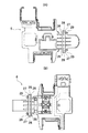
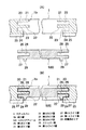
図1〜図9は本発明の一実施形態を示し、図1は本発明の誤結合防止構造を適用した電気接続箱の分解斜視図、図2はアッパーカバーを取り除いた電気接続箱の平面図、図3はロアーカバーの平面図、図4(A)は一方のコネクタフレームの平面図、図4(B)は他方のコネクタフレームの平面図、図5(A)はロアーカバーの開口部及びコネクタフレームの概略断面図、図5(B)はコネクタフレームがロアーカバーの開口部に正規な挿入位置で挿入された状態を示す断面図、図6は接続箱本体の分解斜視図、図7はコネクタフレームをロアーカバーに装着する前の状態を示す断面図、図8はコネクタフレームの第1スライド壁が外れる方向に誤挿入される場合を示す断面図、図9はコネクタフレームの第2スライド壁が外れる方向に誤挿入される場合を示す断面図である。
【0013】
図1及び図2において、電気接続箱Aは、上部が開口1aしたロアーカバー1と、このロアーカバー1内に収容される接続箱本体2及びリレーボックス3と、下部が開口4aし、ロアーカバー1の開口1aを閉鎖するアッパーカバー4と、ロアーカバー1の側面に形成された開口部1bを塞ぐようにロアーカバー1にスライド結合される2つのコネクタフレーム5、6とから主に構成されている。ロアーカバー1及びアッパーカバー4は合成樹脂製である。
【0014】
接続箱本体2は、図6に示すように、上面に部品等が搭載される部品装着部10aを多数有するメインカバー10と、このメインカバー10の下方内側スペースの下面を覆うアンダーカバー11と、これらの内部スペースに配置される中継端子12と、同じく内部スペースに配置されるブスバー13及び絶縁板14で組付けられる配線板15とから構成されている。リレーボックス3は、図1及び図2に示すように、その上面に部品装着部3aが多数設けられており、この部品装着部3aにはリレー等の部品が搭載される。
【0015】
コネクタフレーム5、6は、例えばワイヤ−ワイヤコネクタ(図示せず)等が装着されるもので、上記したようにロアーカバー1にスライド結合され、この結合構造を詳しく説明する。図1〜図5及び図7に示すように、ロアーカバー1の開口部1bは縦方向に長く、上端側が開放されている。この開口部1bの両側の内壁には、図5に詳しく示すように、上下方向(スライド方向)に沿って第1ガイド溝20と、この第1ガイド溝20を形成する第1ガイド壁21及び第2ガイド壁22と、第1ガイド溝20に並設される第2ガイド溝23を第2ガイド壁22との間に形成すると共に第1ガイド壁21及び第2ガイド壁22より短い第3ガイド壁24とが設けられている。つまり、ロアーカバー1の内側から外側に向かって第1ガイド壁21、第1ガイド溝20、第2ガイド壁22、第2ガイド溝23及び第3ガイド壁24の順に配置されている。又、第3ガイド壁24の外周面には下記する第1スライド壁26が第2ガイド溝23に挿入され、下記する第2スライド壁27が第3ガイド壁24の外側の位置に誤挿入されたときに第2スライド壁27に突き当たるストッパー壁25が設けられている。
【0016】
コネクタフレーム5、6の両側面には、第1ガイド溝20にスライド結合される第1スライド壁26と、第2ガイド溝23にスライド結合される第2スライド壁27と、第1スライド壁26が第1ガイド溝20に、第2スライド壁27が第2ガイド溝23にスライド結合されると第2ガイド壁22がスライド結合する第1スライド溝28とが設けられている。つまり、コネクタフレーム5、6の内側から外側に向かって第1スライド壁26、第1スライド溝28及び第2スライド壁27の順に配置されている。又、第2スライド壁27の外周面には、第1スライド壁26が第1ガイド溝20に、第2スライド壁27が第2ガイド溝23に挿入されたときに第3ガイド壁24に突き当たらず、且つ、第1スライド壁26が第1ガイド壁21の外側の位置に、第2スライド壁27が第1ガイド溝20に誤挿入されたときに第2ガイド壁22に突き当たる位置決めリブ29が設けられている。
【0017】
この位置決めリブ29は第1スライド壁26及び第2スライド壁27よりも下方に延設され、この延設部分には、誤結合時に第1スライド壁26及び第2スライド壁27を正規な挿入位置へ案内するガイド面(図示せず)が設けられている。このガイド面(図示せず)は、第1スライド壁26、第1スライド溝28及び第2スライド壁27がロアーカバー1側の第1ガイド壁21、第1ガイド溝20、第2ガイド壁22、第2ガイド溝23及び第3ガイド壁24に接触する前にこれらに接触してコネクタフレーム5、6を正規な挿入位置に案内するものである。
【0018】
次に、コネクタフレーム5、6のスライド結合作業について説明する。図7に示すように、作業者は、コネクタフレーム5、6の下端をロアーカバー1の開口部1bの上方に位置させ、コネクタフレーム5、6の第1スライド壁26がロアーカバー1側の第1ガイド溝20に、第2スライド壁27が第2ガイド溝23に挿入するべく位置合わせを行う。この位置合わせが適正であれば、図5(B)に示すように、位置決めリブ29が第3ガイド壁24に突き当たらず、又、第2スライド壁27がストッパー壁25に突き当たらずにコネクタフレーム5、6のスライド移動が許容される。
【0019】
又、上記の位置合わせが不適正であり、コネクタフレーム5、6の第1スライド壁26がロアーカバー1側の第1ガイド壁20の外側の位置に、第2スライド壁27が第1ガイド溝20に誤挿入されたときには、図8に示すように、位置決めリブ29が第2ガイド壁22に突き当たりコネクタフレーム5、6のスライド移動が阻止されるため、第1スライド壁26がロアーカバー1の内側に外れる方向の誤結合が防止される。このようにコネクタフレーム5、6のスライド移動ができないことによって作業者は、誤挿入であることを認識し挿入位置合わせをやり直す。
【0020】
又、上記の位置合わせが不適正であり、コネクタフレーム5、6の第1スライド壁26がロアーカバー1側の第2ガイド溝23に挿入され、第2スライド壁27が第3ガイド壁24の外側の位置に誤挿入されたときには、図9に示すように、第2スライド壁27がストッパー壁25に突き当たりコネクタフレーム5、6のスライド移動が阻止されるため、第2スライド壁27がロアーカバー1の外側に外れる方向の誤結合が防止される。上記と同様にコネクタフレーム5、6のスライド移動ができないことによって作業者は、誤挿入であることを認識し挿入位置合わせをやり直す。以上より、第1スライド壁26がロアーカバー1の内側に外れる方向と第2スライド壁27がロアーカバー1の外側に外れる方向との両方向の誤結合を防止できる。
【0021】
又、この実施形態では、位置決めリブ29のガイド面(図示せず)によって第1スライド壁26及び第2スライド壁27が正規な挿入位置側に案内されるため、誤挿入される可能性を低下させることができる。
【0022】
【発明の効果】
以上説明したように、請求項1の発明によれば、ロアーカバーの開口部の内壁に第1ガイド壁、第1ガイド溝、第2ガイド壁、第2ガイド溝及び第3ガイド壁を設け、コネクタフレームに第1スライド壁、第1スライド溝及び第2スライド壁を設け、コネクタフレームの第1スライド壁がロアーカバーの第1ガイド壁の外側の位置に、第2スライド壁が前記第1ガイド溝に誤挿入されたときに第2ガイド壁に突き当たる位置決めリブを設けたので、コネクタフレームの第1スライド壁がロアーカバーの第1ガイド溝に、第2スライド壁が第2ガイド溝に挿入されたときに位置決めリブが第3ガイド壁に突き当たらずにコネクタフレームのスライド移動が許容され、又、コネクタフレームの第1スライド壁が第1ガイド壁の外側の位置に、第2スライド壁が第1ガイド溝に誤挿入されたときには位置決めリブが第2ガイド壁に突き当たりコネクタフレームのスライド移動が阻止されるため、第1スライド壁が外れる方向の誤結合が防止される。
【0023】
請求項2の発明によれば、請求項1記載の誤結合防止構造であって、ロアーカバーの第3ガイド壁の外周面に第1スライド壁が第2ガイド溝に挿入され、第2スライド壁が第3ガイド壁の外側の位置に誤挿入されたときに第2スライド壁に突き当たるストッパー壁を設けたので、請求項1の発明の効果に加え、コネクタフレームの第1スライド壁が第2ガイド溝に挿入され、第2スライド壁が第3ガイド壁の外側の位置に誤挿入されたときには第2スライド壁がストッパー壁を突き当たりコネクタフレームのスライド移動が阻止されるため、第2スライド壁が外れる方向の誤結合が防止される。以上より、両方向の誤結合を防止できる。
【図面の簡単な説明】
【図1】本発明の一実施形態を示し、本発明の誤結合防止構造を適用した電気接続箱の分解斜視図である。
【図2】本発明の一実施形態を示し、アッパーカバーを取り除いた電気接続箱の平面図である。
【図3】本発明の一実施形態を示し、ロアーカバーの平面図である。
【図4】本発明の一実施形態を示し、(A)は一方のコネクタフレームの平面図、(B)は他方のコネクタフレームの平面図である。
【図5】本発明の一実施形態を示し、(A)はロアーカバーの開口部及びコネクタフレームの概略断面図、(B)はコネクタフレームがロアーカバーの開口部に正規な挿入位置で挿入された状態を示す断面図である。
【図6】本発明の一実施形態を示し、接続箱本体の分解斜視図である。
【図7】本発明の一実施形態を示し、コネクタフレームをロアーカバーに装着する前の状態を示す断面図である。
【図8】本発明の一実施形態を示し、コネクタフレームの第1スライド壁が外れる方向に誤挿入される場合を示す断面図である。
【図9】本発明の一実施形態を示し、コネクタフレームの第2スライド壁が外れる方向に誤挿入される場合を示す断面図である。
【符号の説明】
A 電気接続箱
1 ロアーカバー
1b 開口部
5、6 コネクタフレーム
20 第1ガイド溝
21 第1ガイド壁
22 第2ガイド壁
23 第2ガイド溝
24 第3ガイド壁
25 ストッパー壁
26 第1スライド壁
27 第2スライド壁
28 第1スライド溝
29 位置決めリブ[0001]
BACKGROUND OF THE INVENTION
The present invention relates to a miscoupling prevention structure that prevents miscoupling when a connector frame is slidably coupled to an opening of a lower cover.
[0002]
[Prior art]
For example, in an electrical junction box, a guide groove and a guide wall are provided on the inner wall of the opening of the lower cover, a slide wall and a slide groove are provided on the surface of the connector frame facing this, and a connector frame is provided on the opening of the lower cover. There has been proposed one in which a connector frame is mounted by sliding connection. In such a conventional structure that is slidably coupled, it is necessary for an operator to align and attach the slide wall of the connector frame to the guide groove of the lower cover.
[0003]
[Problems to be solved by the invention]
However, in the assembly work of the connector frame, if the alignment between the guide groove and the slide wall is not accurately performed, the slide frame may be slid with the slide wall inserted into a different guide groove. Become.
[0004]
Therefore, the present invention has been made to solve the above-described problems, and an object thereof is to provide a miscoupling prevention structure that can prevent miscoupling when a connector frame is slidably coupled to an opening of a lower cover. .
[0005]
[Means for Solving the Problems]
The invention of
[0006]
In this incorrect coupling prevention structure, the positioning rib does not hit the third guide wall when the first slide wall of the connector frame is inserted into the first guide groove of the lower cover and the second slide wall is inserted into the second guide groove. The connector frame is allowed to slide, and when the first slide wall of the connector frame is inserted into a position outside the first guide wall and the second slide wall is erroneously inserted into the first guide groove, the positioning rib is second. The connector frame slides against the guide wall and is prevented from sliding.
[0007]
The invention of
[0008]
In this erroneous coupling prevention structure, in addition to the operation of the invention of
[0011]
DETAILED DESCRIPTION OF THE INVENTION
Hereinafter, an embodiment of the present invention will be described with reference to the drawings.
[0012]
1 to 9 show an embodiment of the present invention, FIG. 1 is an exploded perspective view of an electrical junction box to which the miscoupling prevention structure of the present invention is applied, and FIG. 2 is a plan view of the electrical junction box with an upper cover removed. 3 is a plan view of the lower cover, FIG. 4A is a plan view of one connector frame, FIG. 4B is a plan view of the other connector frame, and FIG. 5A is an opening of the lower cover and FIG. FIG. 5B is a cross-sectional view showing a state in which the connector frame is inserted into the opening of the lower cover at a proper insertion position, FIG. 6 is an exploded perspective view of the junction box body, and FIG. FIG. 8 is a cross-sectional view showing a state before the connector frame is attached to the lower cover, FIG. 8 is a cross-sectional view showing a case where the first slide wall of the connector frame is erroneously inserted in the disengagement direction, and FIG. 9 is a second slide wall of the connector frame. Incorrect insertion direction It is a sectional view showing the case being.
[0013]
1 and 2, the electrical connection box A includes a
[0014]
As shown in FIG. 6, the
[0015]
The
[0016]
On both side surfaces of the
[0017]
The
[0018]
Next, the slide coupling operation of the connector frames 5 and 6 will be described. As shown in FIG. 7, the operator positions the lower ends of the connector frames 5, 6 above the
[0019]
Further, the above-mentioned alignment is inappropriate, the
[0020]
Further, the above alignment is inappropriate, the
[0021]
Further, in this embodiment, since the
[0022]
【The invention's effect】
As described above, according to the invention of
[0023]
According to a second aspect of the present invention, there is provided a structure for preventing erroneous coupling according to the first aspect, wherein the first slide wall is inserted into the second guide groove on the outer peripheral surface of the third guide wall of the lower cover, and the second slide wall In addition to the effect of the invention of
[Brief description of the drawings]
FIG. 1 is an exploded perspective view of an electrical junction box to which an incorrect coupling preventing structure of the present invention is applied according to an embodiment of the present invention.
FIG. 2 is a plan view of an electrical junction box with an upper cover removed according to an embodiment of the present invention.
FIG. 3 is a plan view of a lower cover according to an embodiment of the present invention.
4A and 4B show an embodiment of the present invention, in which FIG. 4A is a plan view of one connector frame, and FIG. 4B is a plan view of the other connector frame.
5A and 5B show an embodiment of the present invention, in which FIG. 5A is a schematic cross-sectional view of an opening of a lower cover and a connector frame, and FIG. 5B is a schematic view of the connector frame inserted into the opening of the lower cover at a proper insertion position. It is sectional drawing which shows the state.
FIG. 6 is an exploded perspective view of a junction box body according to the embodiment of the present invention.
FIG. 7 is a cross-sectional view showing a state before the connector frame is attached to the lower cover according to the embodiment of the present invention.
FIG. 8 is a cross-sectional view illustrating a case where the first slide wall of the connector frame is erroneously inserted in a direction in which the first slide wall is removed, showing an embodiment of the present invention.
FIG. 9 is a cross-sectional view illustrating a case where the second slide wall of the connector frame is erroneously inserted in a direction in which the second slide wall is removed according to the embodiment of the present invention.
[Explanation of symbols]
A
Claims (2)
前記ロアーカバーに設けられた開口部に前記コネクタフレームをスライド移動によって結合する構造であって、
前記ロアーカバーの前記開口部の内壁にスライド方向に沿って設けられた第1ガイド溝と、この第1ガイド溝を形成するスライド方向と交差する方向に同等の長さを有した第1ガイド壁及び第2ガイド壁と、前記第1ガイド溝に並設される第2ガイド溝を前記第2ガイド壁との間に形成すると共に前記第1ガイド壁及び前記第2ガイド壁よりスライド方向と交差する方向に短い第3ガイド壁と、
前記コネクタフレームに設けられ、前記第1ガイド溝にスライド結合される第1スライド壁と、前記第2ガイド溝にスライド結合される第2スライド壁と、前記第2スライド壁の前記第1スライド壁が形成される側とは反対側の外周面に設けられ、結合時に前記第3ガイド壁の前記第1ガイド壁及び第2ガイド壁より短く形成された領域に位置する位置決めリブとを備え、
前記位置決めリブは、前記第1スライド壁が前記第1ガイド壁の外側の位置に、前記第2スライド壁が前記第1ガイド溝に誤挿入されたときに前記第2ガイド壁に突き当たることを特徴とする誤結合防止構造。Used for electrical junction boxes with lower cover and connector frame,
The connector frame is coupled to an opening provided in the lower cover by sliding movement,
A first guide groove provided along the sliding direction on the inner wall of the opening of the lower cover, and a first guide wall having an equivalent length in a direction intersecting the sliding direction for forming the first guide groove And a second guide wall and a second guide groove arranged in parallel with the first guide groove are formed between the second guide wall and intersecting the sliding direction from the first guide wall and the second guide wall. A third guide wall that is short in the direction of
Wherein provided on the connector frame, wherein the first slide wall is slid coupled to the first guide groove, and the second slide wall is slid coupled to the second guide groove, before Symbol the first slide of the second slide wall A positioning rib provided on the outer peripheral surface opposite to the side on which the wall is formed, and positioned in a region formed shorter than the first guide wall and the second guide wall of the third guide wall when coupled;
The positioning rib, the outer position of the first slide wall the first guide wall, that abutment on the second guide wall when the second slide wall is erroneously inserted into the first guide groove decoupling structure erroneous characterized and this.
前記ロアーカバーの前記第3ガイド壁の外周面に設けられ、前記第1スライド壁が前記第2ガイド溝に挿入され、前記第2スライド壁が前記第3ガイド壁の外側の位置に誤挿入されたときに前記第2スライド壁に突き当たるストッパー壁を有することを特徴とする誤結合防止構造。A misbonding prevention structure according to claim 1,
Provided on the outer peripheral surface of the third guide wall of the lower cover, the first slide wall is inserted into the second guide groove, and the second slide wall is erroneously inserted at a position outside the third guide wall. And a stopper wall that abuts against the second slide wall.
Priority Applications (1)
| Application Number | Priority Date | Filing Date | Title |
|---|---|---|---|
| JP2000131010A JP3737672B2 (en) | 2000-04-28 | 2000-04-28 | Misbonding prevention structure |
Applications Claiming Priority (1)
| Application Number | Priority Date | Filing Date | Title |
|---|---|---|---|
| JP2000131010A JP3737672B2 (en) | 2000-04-28 | 2000-04-28 | Misbonding prevention structure |
Publications (2)
| Publication Number | Publication Date |
|---|---|
| JP2001314014A JP2001314014A (en) | 2001-11-09 |
| JP3737672B2 true JP3737672B2 (en) | 2006-01-18 |
Family
ID=18639991
Family Applications (1)
| Application Number | Title | Priority Date | Filing Date |
|---|---|---|---|
| JP2000131010A Expired - Fee Related JP3737672B2 (en) | 2000-04-28 | 2000-04-28 | Misbonding prevention structure |
Country Status (1)
| Country | Link |
|---|---|
| JP (1) | JP3737672B2 (en) |
Families Citing this family (2)
| Publication number | Priority date | Publication date | Assignee | Title |
|---|---|---|---|---|
| JP6297948B2 (en) * | 2014-08-27 | 2018-03-20 | 矢崎総業株式会社 | Electrical junction box |
| JP6277110B2 (en) * | 2014-11-14 | 2018-02-07 | 住友電装株式会社 | Electrical junction box |
-
2000
- 2000-04-28 JP JP2000131010A patent/JP3737672B2/en not_active Expired - Fee Related
Also Published As
| Publication number | Publication date |
|---|---|
| JP2001314014A (en) | 2001-11-09 |
Similar Documents
| Publication | Publication Date | Title |
|---|---|---|
| US7544074B2 (en) | Electrical plug connector assembly having a defined plug-in sequence | |
| JP3140336B2 (en) | Movable connector mounting structure | |
| KR101527057B1 (en) | Plug connector housing with a fixing for an electric contact element and a cable | |
| JPS635868B2 (en) | ||
| US20090221190A1 (en) | Electric connector housing | |
| JP5936065B2 (en) | Electrical junction box | |
| JPS5933942B2 (en) | electrical connectors | |
| JPH0548241U (en) | Connector assembly structure | |
| JP4032925B2 (en) | connector | |
| JP3737672B2 (en) | Misbonding prevention structure | |
| US6155851A (en) | Connector locking structure | |
| KR101719139B1 (en) | Joint Connector with busbar | |
| KR20170085941A (en) | Connector | |
| JP4293254B2 (en) | connector | |
| US6250954B1 (en) | Electrical connection box | |
| JP4151535B2 (en) | Exposed modular jack | |
| JP3887198B2 (en) | Connector spacer | |
| JP4200010B2 (en) | Anti-vibration and waterproof wire harness connector with compact locking element | |
| JP4079062B2 (en) | Exposed modular jack | |
| JP2571483Y2 (en) | cover | |
| KR960002348Y1 (en) | Cable connector | |
| JP4139287B2 (en) | Electrical junction box | |
| JP3753018B2 (en) | connector | |
| JP2003164037A (en) | Electric joint box | |
| JP4209786B2 (en) | Connector structure |
Legal Events
| Date | Code | Title | Description |
|---|---|---|---|
| A977 | Report on retrieval |
Free format text: JAPANESE INTERMEDIATE CODE: A971007 Effective date: 20040730 |
|
| A131 | Notification of reasons for refusal |
Free format text: JAPANESE INTERMEDIATE CODE: A131 Effective date: 20041026 |
|
| A521 | Written amendment |
Free format text: JAPANESE INTERMEDIATE CODE: A523 Effective date: 20041208 |
|
| A131 | Notification of reasons for refusal |
Free format text: JAPANESE INTERMEDIATE CODE: A131 Effective date: 20050329 |
|
| A521 | Written amendment |
Free format text: JAPANESE INTERMEDIATE CODE: A523 Effective date: 20050526 |
|
| TRDD | Decision of grant or rejection written | ||
| A01 | Written decision to grant a patent or to grant a registration (utility model) |
Free format text: JAPANESE INTERMEDIATE CODE: A01 Effective date: 20051018 |
|
| A61 | First payment of annual fees (during grant procedure) |
Free format text: JAPANESE INTERMEDIATE CODE: A61 Effective date: 20051027 |
|
| R150 | Certificate of patent or registration of utility model |
Ref document number: 3737672 Country of ref document: JP Free format text: JAPANESE INTERMEDIATE CODE: R150 Free format text: JAPANESE INTERMEDIATE CODE: R150 |
|
| FPAY | Renewal fee payment (event date is renewal date of database) |
Free format text: PAYMENT UNTIL: 20091104 Year of fee payment: 4 |
|
| FPAY | Renewal fee payment (event date is renewal date of database) |
Free format text: PAYMENT UNTIL: 20091104 Year of fee payment: 4 |
|
| FPAY | Renewal fee payment (event date is renewal date of database) |
Free format text: PAYMENT UNTIL: 20101104 Year of fee payment: 5 |
|
| FPAY | Renewal fee payment (event date is renewal date of database) |
Free format text: PAYMENT UNTIL: 20111104 Year of fee payment: 6 |
|
| FPAY | Renewal fee payment (event date is renewal date of database) |
Free format text: PAYMENT UNTIL: 20121104 Year of fee payment: 7 |
|
| FPAY | Renewal fee payment (event date is renewal date of database) |
Free format text: PAYMENT UNTIL: 20121104 Year of fee payment: 7 |
|
| FPAY | Renewal fee payment (event date is renewal date of database) |
Free format text: PAYMENT UNTIL: 20131104 Year of fee payment: 8 |
|
| R250 | Receipt of annual fees |
Free format text: JAPANESE INTERMEDIATE CODE: R250 |
|
| R250 | Receipt of annual fees |
Free format text: JAPANESE INTERMEDIATE CODE: R250 |
|
| R250 | Receipt of annual fees |
Free format text: JAPANESE INTERMEDIATE CODE: R250 |
|
| R250 | Receipt of annual fees |
Free format text: JAPANESE INTERMEDIATE CODE: R250 |
|
| LAPS | Cancellation because of no payment of annual fees |