JP3736183B2 - Electric brake device - Google Patents
Electric brake device Download PDFInfo
- Publication number
- JP3736183B2 JP3736183B2 JP06823699A JP6823699A JP3736183B2 JP 3736183 B2 JP3736183 B2 JP 3736183B2 JP 06823699 A JP06823699 A JP 06823699A JP 6823699 A JP6823699 A JP 6823699A JP 3736183 B2 JP3736183 B2 JP 3736183B2
- Authority
- JP
- Japan
- Prior art keywords
- brake
- brake operation
- value
- relationship
- driving force
- Prior art date
- Legal status (The legal status is an assumption and is not a legal conclusion. Google has not performed a legal analysis and makes no representation as to the accuracy of the status listed.)
- Expired - Fee Related
Links
Images


Description
【0001】
【発明の属する技術分野】
本発明は、モータを駆動源とするブレーキを備えた車両用の電動式ブレーキ装置に関するものであり、特に、そのモータの駆動力を制御する技術の改良に関するものである。
【0002】
【従来の技術】
車両用のブレーキ装置の分野においては、モータを用いてブレーキを電気的に作動させる電動式ブレーキ装置が既に知られている。そして、特開平10−331876号公報には、次のような電動式ブレーキ装置が開示されている。それは、(a) ブレーキペダル等、運転者により操作されるブレーキ操作部材と、(b) ブレーキ操作部材の操作力,操作ストローク等、操作値を検出するブレーキ操作値センサと、(c) ブレーキと、(d) コントローラとを含むように構成されている。
【0003】
ブレーキは、電源から供給される電力により駆動されるモータの駆動力(駆動トルクを含む概念)により摩擦材を、車輪と共に回転する回転体に押し付け、それにより、その回転体に制動トルクを発生させ、その発生させられた制動トルクにより車輪を制動するように構成される。ブレーキには、ブレーキパッドを摩擦材、ディスクを回転体としてそれぞれ備えたディスク式と、ブレーキライニングを摩擦材、ドラムを回転体としてそれぞれ備えたドラム式とがある。
【0004】
コントローラは、ブレーキ操作部材の操作値とモータの駆動力との間に予め定められた関係に従い、かつ、ブレーキ操作値センサにより検出されたブレーキ操作値に基づき、モータの駆動力を制御するように構成される。
【0005】
【発明が解決しようとする課題,課題解決手段および発明の効果】
この種の電動式ブレーキ装置においては、モータ駆動力と制動トルクとの関係が常に一定であるとは限らず、時間的に変化する場合がある。以下、具体的に説明する。
【0006】
例えば、ブレーキが通常のドラム式である場合等、ブレーキがセルフサーボ効果を発生可能な形式である場合には、モータ駆動力が制動トルクに変換される比率であるブレーキ効力係数BEFが常に一定であるわけではなく、ブレーキ操作値が一定であっても時間と共に増加する。そのため、ブレーキがセルフサーボ効果を発生可能な形式である場合には、ブレーキ操作値の時間的変化に起因しない時間的変化が制動トルクに発生する。よって、特に、ブレーキ操作に伴って車速が低下するにつれて、運転者は車体減速度の変化に違和感を感じる。
【0007】
ブレーキ効力係数BEFは摩擦材の摩擦係数μに依存する。具体的には、ブレーキ効力係数BEFは、それが大きい領域において小さい領域におけるより敏感に摩擦材の摩擦係数μの変化に対して変化させられる。このことは図7にグラフで示されている。その結果、制動トルクも、ブレーキ効力係数BEFが大きい領域において小さい領域におけるより敏感に摩擦材の摩擦係数μの変化に対して変化させられる。一方、摩擦材の摩擦係数μは、その摩擦材の温度に依存し、摩擦材の温度は、ブレーキが連続して作動させられる時間の増加につれて上昇する。そのため、ブレーキがセルフサーボ効果を発生可能な形式である場合には、摩擦材の温度変化に起因した摩擦材の摩擦係数μの時間的変化によっても、ブレーキ操作値の時間的変化に起因しない時間的変化が制動トルクに発生する。
【0008】
ブレーキが通常のディスク式である場合等、ブレーキがセルフサーボ効果を発生させない形式である場合にも、ブレーキ効力係数BEFが、ブレーキ操作値が一定であっても時間と共に増加することがある。例えば、車両の走行速度が約30km/h以下である状態等、車両が低速走行させられている状態では、ブレーキ操作値を一定にしても、ブレーキ効力係数BEFが時間と共に増加することがあるのである。これは、摩擦材が回転体に食いつくことが原因であると予想される。そのため、ブレーキがセルフサーボ効果を発生させない形式である場合にも、ブレーキ操作値の時間的変化に起因しない時間的変化が制動トルクに発生することがある。
【0009】
ブレーキ操作値の時間的変化に起因しない時間的変化が制動トルクに発生することは、その原因の種類の如何を問わず、運転者のブレーキ操作フィーリングを悪化させる要因となる。そのため、上記電動式ブレーキ装置においては、このような制動トルクの時間的変化を考慮しないでモータ駆動力が制御されると、ブレーキ操作フィーリングが悪化するおそれがある。
【0010】
このような事情を背景として、本発明は、モータ駆動力をブレーキ操作値との関係において適正化することを課題としてなされたものであり、本発明によって下記各態様が得られる。各態様は、請求項と同様に、項に区分し、各項に番号を付し、必要に応じて他の項の番号を引用する形式で記載する。これは、本明細書に記載の技術的特徴およびそれらの組合せのいくつかの理解を容易にするためであり、本明細書に記載の技術的特徴やそれらの組合せが以下の態様に限定されると解釈されるべきではない。
【0011】
(1)運転者により操作されるブレーキ操作部材と、
そのブレーキ操作部材の操作力または操作ストロークである操作値を検出するブレーキ操作値センサと、
電力により駆動されるモータの駆動力により摩擦材を、車輪と共に回転する回転体に押し付け、それにより、その回転体に制動トルクを発生させ、その発生させられた制動トルクにより車輪を制動し、セルフサーボ効果を発生可能なブレーキと、
前記ブレーキ操作部材の操作値と前記モータの駆動力との間の予め定められた関係に従い、かつ、前記ブレーキ操作値センサにより検出されたブレーキ操作値に基づき、モータの駆動力を制御するコントローラと
を含む電動式ブレーキ装置において、
前記摩擦材の温度を検出する温度センサと、
一連のブレーキ操作中において、前記温度センサにより検出された温度が高く、前記制動トルクをモータ駆動力で割った値であるブレーキ効力係数が、前記摩擦材の摩擦係数の変化に起因して大きく変化させられる温度領域にある場合には、前記温度が低く、前記ブレーキ効力係数の前記摩擦材の摩擦係数の変化に起因する変化が小さい温度領域にある場合より、同じブレーキ操作値に対応する前記モータの駆動力が小さくなるように前記関係を変化させる関係変化装置と
を含むことを特徴とする電動式ブレーキ装置(請求項1)。
(2)運転者により操作されるブレーキ操作部材と、
そのブレーキ操作部材の操作力または操作ストロークである操作値を検出するブレーキ操作値センサと、
電力により駆動されるモータの駆動力により摩擦材を、車輪と共に回転する回転体に押し付け、それにより、その回転体に制動トルクを発生させ、その発生させられた制動トルクにより車輪を制動するブレーキと、
前記ブレーキ操作部材の操作値と前記モータの駆動力との間に予め定められた関係に従い、かつ、前記ブレーキ操作値センサにより検出されたブレーキ操作値に基づき、モータの駆動力を制御するコントローラと
を含む電動式ブレーキ装置において、
一連のブレーキ操作中において、前記ブレーキの作動が連続するブレーキ作動連続時間が、前記摩擦材の温度が高くなることにより摩擦材の摩擦係数の変化が大きくなり、前記ブレーキ操作値が一定であっても、前記摩擦材の摩擦係数の変化に伴って制動トルクが変化し始める時間である基準時間を超えた場合には、越える以前より、同じブレーキ操作値に対応する前記モータの駆動力が小さくなるように前記関係を変化させる関係変化装置を設けたことを特徴とする電動式ブレーキ装置(請求項2)。
この電動式ブレーキ装置によれば、前記関係が、一連のブレーキ操作中一定とされるのではなく、一連のブレーキ操作中に変化させられる。そして、この電動式ブレーキ装置によれば、一連のブレーキ操作中に、ブレーキ操作値の時間的変化に起因しない時間的変化が制動トルクに実質的に生じないように前記関係を変化させることが可能である。したがって、この電動式ブレーキ装置によれば、モータ駆動力をブレーキ操作値との関係において適正化し得、その結果、良好なブレーキ操作フィーリングを得ることが可能となる。
この電動式ブレーキ装置において「一連のブレーキ操作中に前記関係を変化させる」形式には、一連のブレーキ操作の途中で1回、前記関係を変化させる形式を選んだり、複数回変化させる形式を選ぶことができる。1回変化させる形式は、一連のブレーキ操作中に前記関係を2段階に変化させる形式であるということができ、また、複数回変化させる形式は、一連のブレーキ操作中に前記関係を3段階以上に変化させる形式であるということができる。
この電動式ブレーキ装置において「一連のブレーキ操作」は、ブレーキ操作部材の操作を開始してから、その開始時から最初にその操作を終了するまでの、運転者の動作をいう。
この電動式ブレーキ装置において「前記関係を変化させる」技術は、モータに供給される電力値(以下、「モータ電力値」という)とモータ駆動力とが1対1に対応する場合には、ブレーキ操作値に応じてモータ電力値を決定する過程においては、それらブレーキ操作値とモータ電力値との関係を変化させる技術として実現でき、また、ブレーキ操作値に応じて車体減速度の目標値を決定してその目標減速度に応じてモータ電力値を決定する過程においては、ブレーキ操作値と目標減速度との関係を変化させる技術として実現できる。また、モータ電力値とモータ駆動力との関係を電気的にまたは機械的に変化させ得る場合には、その関係を変化させる技術として実現できる。
この電動式ブレーキ装置においては、ブレーキをドラム式としたり、ディスク式とすることができる。また、ディスク式のブレーキは、セルフサーボ効果を発生可能な形式としたり、発生させない形式とすることができる。
この電動式ブレーキ装置において「前記関係」は、ブレーキ操作値の増加につれてモータ駆動力が増加することを表す連続的な関係(例えばパターン)としたり、ある瞬間におけるブレーキ操作値とモータ駆動力との関係とすることができる。
(1)項に記載の電動ブレーキ装置においては、一連のブレーキ操作中に摩擦材の温度が検出され、その温度を考慮して前記関係が変化させられる。摩擦材等の温度が高いためにモータ駆動力を小さくすることが望ましい場合にモータ駆動力が小さくされ、それにより、制動トルクの変化が抑制されるため、ブレーキ操作フィーリングが向上する。また、本電動式ブレーキ装置によれば、温度の検出が一連のブレーキ操作中に行われる。よって、温度の変化に精度よく追従するように前記関係をリアルタイムで変化させることが容易となり、その結果、モータ駆動力の制御精度を容易に向上させ得る。
(2)項に記載の電動ブレーキ装置において、ブレーキ作動連続時間が経過するにつれて、摩擦材またはそれの近傍の温度が上昇するのであり、ブレーキ作動連続時間と摩擦材等の温度との間には一定の関係が成立する。そこで、ブレーキ作動連続時間が長いためモータ駆動力を小さくすることが望ましい場合にモータ駆動力が小さくされれば、制動トルクの変化を抑制することができ、ブレーキ操作フィーリングを向上させることができる。また、本電動式ブレーキ装置によれば、モータ駆動力をブレーキ操作値との関係において適正化することができる。
( 3 )前記関係変化装置が、前記ブレーキ作動連続時間が前記基準時間を越え、かつ、前記ブレーキ操作部材が定常操作状態にある場合には、車両の走行速度または車輪の回転速度である速度が小さい場合は大きい場合より同じブレーキ操作値に対応する前記モータの駆動力が小さくなるように前記関係を変化させる第2の変化手段を含む(2)項に記載の電動式ブレーキ装置(請求項3)。
( 4 )前記関係変化装置が、一連のブレーキ操作中における車両の走行速度または車輪の回転速度である速度が小さい場合は大きい場合より同じブレーキ操作値に対応する前記モータの駆動力が小さくなるように前記関係を変化させる第1の変化手段を含む(1)項ないし (3) 項のいずれか1つに記載の電動式ブレーキ装置(請求項4)。
前述のように、車両の走行速度または車輪の回転速度が小さい場合において大きい場合におけるより、摩擦材の回転体への食いつきが生じ易く、よって、ブレーキ操作値の時間的増加に起因しない制動トルクの時間的増加が発生する可能性が高い。
また、車両の走行速度が小さい場合において大きい場合におけるより、運転者は、ブレーキ操作値の時間的変化に起因しない制動トルクの時間的変化をブレーキ操作フィーリングの時間的変化として感じ易く、よって、ブレーキ操作値の時間的変化に起因しない制動トルクの時間的変化を抑制する必要性が高い。
また、ブレーキ操作フィーリングの悪化防止は、車両の走行速度が小さい場合において大きい場合におけるより強く要望される事項であるのに対して、ブレーキの効き増加は、車両の走行速度が大きい場合において小さい場合におけるより強く要望される事項であると考えられる。一方、ブレーキ操作値の時間的増加に起因しない制動トルクの時間的増加は、ブレーキの効きが増すことを意味する。したがって、車両の走行速度が大きい場合にはブレーキの効き増加を優先させる一方、車両の走行速度が小さい場合にはブレーキ操作フィーリングの悪化防止を優先させることが考えられ、その考えに従えば、車両の走行速度が小さい場合において大きい場合におけるより、ブレーキ操作値の時間的増加に起因しない制動トルクの時間的増加を抑制することは妥当なことである。
本項に記載の電動式ブレーキ装置においては、車両の走行速度または車輪の回転速度が小さいためにモータ駆動力を小さくすることが望ましい場合にモータ駆動力が小さくされることにより、制動トルクの変化が抑制されるため、ブレーキ操作フィーリングが向上する。
( 5 )前記第1の変化手段が、同じブレーキ操作値に対応するモータ駆動力が、一連のブレーキ操作の開始時における前記速度であるブレーキ操作開始時速度が第1基準値より小さい場合において大きい場合におけるより小さくなるように前記関係を設定する手段を含む(4)項に記載の電動式ブレーキ装置。
この電動式ブレーキ装置によれば、ブレーキ操作開始時速度が小さい場合と大きい場合とで前記関係が互いに異なるように設定され、その結果、モータ駆動力がブレーキ操作開始時速度との関係において適正化される。
( 6 )前記第1の変化手段が、前記ブレーキ操作開始時速度が前記第1基準値より大きい場合には、同じブレーキ操作値に対応するモータ駆動力が、前記一連のブレーキ操作の開始後における前記速度であるブレーキ操作開始後速度が第2基準値に低下した後の期間において低下する前の期間におけるより小さくなるように前記関係を変化させる手段を含む(5)項に記載の電動式ブレーキ装置。
この電動式ブレーキ装置によれば、ブレーキ操作開始後速度が変化するにつれて前記関係が変化させられ、その結果、ブレーキ操作開始後速度を考慮することにより、モータ駆動力をブレーキ操作値との関係において適正化し得る。
この電動式ブレーキ装置において「第2基準値」は、第1基準値と等しい値としたり、異なる値とすることができる。
( 7 )前記関係変化装置が、前記ブレーキ操作値に時間的変化が実質的に生じていない定常状態にあるか否かに基づいて前記関係を変化させる第4変化手段を含む(1)ないし(6)項のいずれかに記載の電動式ブレーキ装置。
ブレーキ操作値に時間的変化が実質的に生じていない定常状態においてそうでない非定常状態におけるより、運転者は、ブレーキ操作値の時間的変化に起因しない制動トルクの時間的変化をブレーキ操作フィーリングの時間的変化として感じ易い。
このような知見に基づき、本項に記載の電動式ブレーキ装置においては、ブレーキ操作値が定常状態にあるか否かに基づいて前記関係が変化させられる。
( 8 )前記第4変化手段が、同じブレーキ操作値に対応するモータ駆動力が、前記定常状態において非定常状態におけるより小さくなるように前記関係を変化させる手段を含む(7)項に記載の電動式ブレーキ装置。
この電動式ブレーキ装置によれば、運転者が制動トルクの時間的変化を感じ易い、ブレーキ操作値の定常状態において、モータ駆動力が小さくされるため、制動トルクの変化量が低減され、その結果、ブレーキ操作フィーリングの悪化が抑制される。
(9)前記関係が、前記ブレーキ操作値と係数とを掛けた値が前記モータの駆動力の目標値である関係であり、前記関係変化装置が、前記係数を変えることにより前記関係を変化させる手段を含む(1)ないし(8)項のいずれか1つに記載の電動式ブレーキ装置(請求項5)。
ここに「制御ゲイン」は、ブレーキ操作値の変化可能領域の全体について共通のものとしたり、ブレーキ操作値に応じて変化するものとすることができる。
(10)前記関係変化装置が、前記ブレーキ操作値の時間的変化に起因しない時間的変化が前記制動トルクに実質的に生じないように、一連のブレーキ操作中に前記関係を変化させるものである(1)ないし(9)項のいずれか1つに記載の電動式ブレーキ装置。
この電動式ブレーキ装置によれば、一連のブレーキ操作中に、ブレーキ操作値の時間的変化に起因しない時間的変化が制動トルクに実質的に生じないように前記関係が変化させられる。したがって、この電動式ブレーキ装置によれば、良好なブレーキ操作フィーリングが得られる。
(11)前記関係変化装置が、一連のブレーキ操作中における車両の走行速度または車輪の回転速度の変化と、一連のブレーキ操作中に前記ブレーキの作動が連続するブレーキ作動連続時間の経過と、一連のブレーキ操作中における前記摩擦材またはそれの周辺の温度の変化と、一連のブレーキ操作中に前記ブレーキ操作値に時間的変化が実質的に生じない定常状態にあるか否かを表す情報の変化との少なくとも一つに関連して前記関係を変化させるものである(1)ないし(10)項のいずれかに記載の電動式ブレーキ装置。
(12)前記関係変化装置が、前記関係を段階的に変化させるものである(1)ないし(11)項のいずれかに記載の電動式ブレーキ装置。
前記関係変化装置は、前記関係を実質的に連続的に変化させる態様で実施することが可能であるが、段階的に変化させる態様で実施すれば、実質的に連続的に変化させる態様で実施する場合に比較して、前記関係を変化させるための構成、例えば、コンピュータのプログラム,メモリ等の負荷が軽減される。
(13)前記関係変化装置が、前記ブレーキ操作値の時間的変化に起因しない時間的変化が前記制動トルクに生じる可能性の有無を判定する可能性判定手段を含み、その可能性判定手段によりその可能性があると判定された場合に前記関係を変化させるものである(1)ないし(12)項のいずれかに記載の電動式ブレーキ装置。
ここに「可能性判定手段」は例えば、ブレーキ操作値の時間的変化に起因しない時間的変化が制動トルクに生じる可能性が、ブレーキの作動が連続する時間が長い場合において短い場合におけるより高いという事実に着目することにより、その可能性を有無を判定する形式としたり、ブレーキ操作値の時間的変化に起因しない時間的変化が制動トルクに生じる可能性が、摩擦材またはそれの近傍の温度が高い場合において低い場合におけるより高いという事実に着目することにより、その可能性を有無を判定する形式とすることができる。
(14)前記関係変化装置が、さらに、前記ブレーキ操作値の時間的変化に起因しない時間的変化が前記制動トルクに実質的に生じないように前記関係を変化させることが必要であるか否かを判定する必要性判定手段を含み、前記可能性判定手段により、前記ブレーキ操作値の時間的変化に起因しない時間的変化が前記制動トルクに生じる可能性があると判定され、かつ、前記必要性判定手段により、前記ブレーキ操作値の時間的変化に起因しない時間的変化が前記制動トルクに実質的に生じないように前記関係を変化させることが必要であると判定された場合に前記関係を変化させるものである(13)項に記載の電動式ブレーキ装置。
ここに「必要性判定手段」は例えば、ブレーキ操作値の時間的変化に起因しない時間的変化が制動トルクに生じると、運転者はその制動トルクの時間的変化を、車両の走行速度が低い場合において高い場合におけるより感じ易いという事実に着目することにより、ブレーキ操作値の時間的変化に起因しない時間的変化が制動トルクに実質的に生じないように関係を変化させることが必要であるか否かを判定する形式とすることができる。また、ブレーキ操作値の時間的変化に起因しない時間的変化が制動トルクに生じると、運転者はその制動トルクの時間的変化を、ブレーキ操作値の時間的変化がない場合においてある場合におけるより感じ易いという事実に着目することにより、ブレーキ操作値の時間的変化に起因しない時間的変化が制動トルクに実質的に生じないように関係を変化させることが必要であるか否かを判定する形式とすることもできる。
(15)当該電動式ブレーキ装置が、さらに、各回の一連のブレーキ操作ごとに、各回の一連のブレーキ操作の開始時における車両の走行速度または車輪の回転速度であるブレーキ操作開始時速度が小さい場合は大きい場合より同じブレーキ操作値に対応する前記モータの駆動力が小さくなるように前記関係を変化させる関係設定装置を含む(1)項ないし(14)項のいずれか1つに記載の電動式ブレーキ装置(請求項6)。
本発明者らは、ブレーキ操作開始時速度が、ある回の一連のブレーキ操作が、運転者が制動トルクの変化を感じ易い種類のものであるか難い種類のものであるかを判別する際に考慮することが有効なパラメータであることに気がついた。
このような知見に基づき、本項に記載の電動式ブレーキ装置においては、ブレーキ操作開始時速度に基づいて前記関係が設定される。したがって、この電動式ブレーキ装置によれば、一連のブレーキ操作の種類の如何を問わず、モータ駆動力がブレーキ操作値との関係において適正化され、その結果、良好なブレーキ操作フィーリングが得られる。また、運転者が制動トルクの変化を感じ易い低速走行時にブレーキ操作フィーリングが悪化することが抑制される。
(16)運転者により操作されるブレーキ操作部材と、
そのブレーキ操作部材の操作値を検出するブレーキ操作値センサと、
電力により駆動されるモータの駆動力により摩擦材を、車輪と共に回転する回転体に押し付け、それにより、その回転体に制動トルクを発生させ、その発生させられた制動トルクにより車輪を制動するブレーキと、
前記ブレーキ操作部材の操作値と前記モータの駆動力との間に予め定められた関係に従い、かつ、前記ブレーキ操作値センサにより検出されたブレーキ操作値に基づき、モータの駆動力を制御するコントローラと
を含む電動式ブレーキ装置において、
車両の走行速度または車輪の回転速度である速度と、前記ブレーキの作動が連続する時間と、前記摩擦材またはそれの周辺の温度と、前記ブレーキ操作値に時間的変化が実質的に生じない定常状態にあるか否かを表す情報との少なくとも一つに基づいて前記関係を決定する関係決定装置を設けたことを特徴とする電動式ブレーキ装置。
この電動式ブレーキ装置において「前記関係を決定する」という用語は、各回の一連のブレーキ操作ごとに前記関係の初期値を設定することと、各回の一連のブレーキ操作中に前記関係を変化させることとの少なくとも一方を含むように解釈される。
【0012】
【発明の実施の形態】
以下、本発明のさらに具体的な実施の形態のいくつかを図面に基づいて詳細に説明する。
【0013】
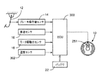
図1には、本発明の第1実施形態である電動式ブレーキ装置の全体構成が示されている。この電動式ブレーキ装置は、左右前輪FL,FRと左右後輪RL,RRとを備えた4輪車両に設けられている。左右前輪FL,FRには超音波モータを駆動源とするとともに流体圧を使用しない電動式ディスクブレーキが設けられている。一方、左右後輪RL,RRには、DCモータを駆動源とするとともに流体圧を使用しない電動式ドラムブレーキが設けられている。ただし、本実施形態を通して本発明を理解するために説明することが特に必要であるのは電動式ドラムブレーキであるため、同図には、左右後輪の一方に設けられた電動式ドラムブレーキ(以下、単に「ブレーキ」という)10のみが代表的に示されている。
【0014】
電動式ブレーキ装置は、ブレーキ10に加えて、ブレーキペダル12をブレーキ操作部材として備えるとともに、図示しない反力付与機構を備えている。ブレーキペダル12は、車両左右方向に延びる一軸線まわりに回動可能に車体に取り付けられている。反力付与機構は、ブレーキペダル12の操作ストロークに応じた反力をブレーキペダル12に発生させる。電動式ブレーキ装置はさらに、ブレーキ操作値センサ14を備えている。ブレーキ操作値センサ14は、ブレーキペダル12の操作力または操作ストロークをブレーキ操作値として検出する。ブレーキ操作値センサ14は、ブレーキペダル12の操作力を歪みゲージ等により検出する形式としたり、ブレーキペダル12の回動角をロータリポテンショメータにより検出する形式とすることができる。
【0015】
電動式ブレーキ装置はさらに、車速センサ16を備えている。車速センサ16は、車両の走行速度である車速Vを検出する。電動式ブレーキ装置はさらに、モータ駆動力センサ18を備えている。モータ駆動力センサ18については後に詳述する。
【0016】
電動式ブレーキ装置はさらに、電子制御ユニット(以下、「ECU」と略称する)20と、電源としてのバッテリ22とを備えている。ECU20は、CPU,ROMおよびRAMを含むコンピュータを主体として構成されている。ROMには、図4および図5にそれぞれにフローチャートで表されているブレーキ制御ルーチンおよび制御ゲイン決定ルーチンを始めとして各種ルーチンが記憶されており、それらルーチンがCPUによりRAMを使用つつ実行されることにより、ブレーキ10が制御される。バッテリ22は、車両のエンジンの回転により充電させられる。
【0017】
図2には、ブレーキ10が拡大されて示されている。
【0018】
ブレーキ10は、図示しない車体に取り付けられた非回転部材としての、ほぼ円板状を成すバッキングプレート200と、内周面に摩擦面202を備えて車輪と共に回転するドラム204とを備えている。同図には、車両前進時に車輪が回転するのに伴ってドラム204が回転するドラム回転方向が矢印で示されている。
【0019】
バッキングプレート200の一直径方向に隔たった2箇所には、それぞれアンカ部材としてのアンカピン206と中継リンクとしてのアジャスタ208とが設けられている。アンカピン206はバッキングプレート200に位置固定に取り付けられている。一方、アジャスタ208はフローティング式とされている。それらアンカピン206とアジャスタ208との間には、各々円弧状を成す一対のブレーキシュー210a,210bがドラム204の内周面に対面するように取り付けられている。一対のブレーキシュー210a,210bは、シューホールドダウン装置212a,212bによってバッキングプレート200にそれの面に沿って移動可能に取り付けられている。なお、バッキングプレート200の中央に設けられた貫通穴には、図示しないアクスルシャフトが回転可能に突出して設けられるようになっている。
【0020】
一対のブレーキシュー210a,210bは、一端部同士がアジャスタ208により相互に接近は不能、隔離は可能に連結される一方、各他端部がアンカピン206と当接させられており、それにより、各端部の回りに回動可能に支持されている。一対のブレーキシュー210a,210bの一端部同士は、アジャスタスプリング214によりアジャスタ208を介して互いに接近する向きに付勢されている。一方、一対のブレーキシュー210a,210bの各他端部は各シューリターンスプリング215a,215bによりアンカピン206に向かって付勢されている。各ブレーキシュー210a,210bの外周面にブレーキライニング216a,216bが保持され、それら一対のブレーキライニング216a,216bがドラム204の内周面に接触させられることにより、それらブレーキライニング216a,216bとドラム204との間に摩擦力が発生する。アジャスタ208は、一対のブレーキライニング216a,216bとドラム204との隙間を一対のブレーキシュー210a,210bの摩耗に応じて自動的に調整する。
【0021】
各ブレーキシュー210a,210bはリム220とウェブ222とから構成されており、一対のブレーキシュー210a,210bの一方のウェブ222には、レバー230がドラム204の回転軸線と交差する方向に回動可能に取り付けられている。ウェブ222にレバー支持部材としてのピン232が位置固定に取り付けられ、そのピン232にレバー230の一端部が回動可能に連結されているのである。このレバー230と他方のブレーキシュー210bとの互いに対向する部分の切欠きには、力伝達部材としてのストラット236の両端が係合させられている。このストラット236はその長さをねじ機構により調節するアジャスト機能を備えている。
【0022】
以上の説明から明らかなように、ブレーキ10は、車体の前進時にも後退時にも、いずれのブレーキシュー210a,210bにもセルフサーボ効果が発生するデュオサーボ型なのである。
【0023】
レバー230の他端部(自由端部)にはケーブル240の一端部が連結されている。このケーブル240は、複数本のワイヤをより合わせて構成されており、フレキシブルである。このケーブル240は、バッキングプレート200に取り付けられたシュー拡張アクチュエータ250により駆動される。シュー拡張アクチュエータ250は、図3に拡大して示すように、DCモータ(以下、単に「モータ」という)251の回転軸に減速機252の入力軸が連結され、その減速機252の出力軸に運動変換機構としてのボールねじ機構254の入力部材が連結されて構成されており、そのボールねじ機構254の出力部材にケーブル240の他端部が連結されている。ボールねじ機構254は、モータ251の回転運動を直線運動に変換する機構である。図において符号256および258は共にブラケットを示し、また、符号260および262は共に、各ブラケット256,258をバッキングプレート200へ取り付けるための取付けボルトを示している。
【0024】
ボールねじ機構254は、入力部材としてのおねじ264に出力部材としてのナット266が図示しない複数個のボールを介して螺合されて構成されている。ナット266は固定部材としてのハウジング267に回転不能かつ軸方向移動可能に嵌合されている。それにより、おねじ264の回転運動がナット266の直線運動に変換される。ナット266の両端部のうちおねじ264の側とは反対側の端部に出力シャフト268が同軸に取り付けられている。それらおねじ264,ナット266および出力シャフト268の相互の摺動部へのダストの侵入が、ハウジング267および伸縮可能なダストブーツ270により阻止されている。
【0025】
出力シャフト268とケーブル240の他端部との結合は次のような構成により行われる。すなわち、出力シャフト268の両端部のうちボールねじ機構254の側とは反対側の端部にケーブル取付け用おねじ272が形成される一方、ケーブル240の他端部にケーブル取付け用ナット274が結合されている。そのケーブル取付け用ナット274がケーブル取付け用おねじ272に螺合され、そのケーブル取付け用おねじ272に回り止め用ナット276が螺合されるとともに、その回り止め用ナット276がケーブル取付け用ナット274に押し付けられることにより、ケーブル取付け用ナット274の緩みが防止されている。
【0026】
以上のように構成されたシュー拡張アクチュエータ250は、ブレーキペダル12の操作時にケーブル240に引張力を付与し、それにより、レバー230がそれの他端部がブレーキシュー210bから離隔される向きに回動させられ、その結果、ストラット236により一対のブレーキシュー210a,210bが拡張される。
【0027】
ブレーキ10は、一対のブレーキシュー210a,210bをそれに発生するセルフサーボ効果に打ち勝って収縮させるのに効果的なシュー収縮機構を備えている。シュー収縮機構は、本実施形態においては、図2に示すように、レバー230とバッキングプレート200との間に張り渡されたリターンスプリング280とされている。このリターンスプリング280は、ケーブル240と同軸に張り渡されるとともに、一端部がレバー230の他端部に、他端部がシュー拡張アクチュエータ250のうちの固定部分(例えば、ハウジング,ブラケット等)にそれぞれ係合させられている。したがって、ブレーキペダル12の操作の解除時に、シュー拡張アクチュエータ250が初期位置に向かって戻されれば、レバー230はリターンスプリング280の圧縮力によって初期位置に向かって回動させられる。
【0028】
前記モータ駆動力センサ18は、レバー230に装着されている。モータ駆動力センサ18は、歪みゲージ方式であり、レバー230に生じた歪みを検出するとともに、その検出した歪みに基づいてそのレバー230にモータ251が加えたモータ駆動力Dを検出する。
【0029】
なお、モータ駆動力センサ18は、他の方式でモータ駆動力Dを検出するものとすることが可能である。例えば、モータ251に供給された電流を検出するモータ電流センサをそのモータ251に設け、かつ、モータ251に供給された電流と、そのモータ251がレバー230に加えたモータ駆動力Dとの間に成立する一定の関係を利用することにより、モータ電流センサにより検出された電流からモータ駆動力Dを検出することが可能なのである。
【0030】
以上説明したブレーキ10のモータ251はECU20のコンピュータにより制御される。以下、この制御を説明するが、まず、概略的に説明し、次に、図4および図5のフローチャートを参照しつつ具体的に説明する。
【0031】
ECU20は、ブレーキ操作値Aに基づき、ブレーキ10により発生させる車体減速度の目標値である目標減速度G* を決定する。
【0032】
ECU20はさらに、決定された目標減速度G* に制御ゲインk(係数)を掛け算することにより、モータ駆動力の目標値である目標駆動力D* を決定する。すなわち、目標駆動力D* は、
D* =k×G*
なる式を用いて決定されるのである。
【0033】
なお、目標減速度G* は、ブレーキ操作値Aに対応する値であることから、モータ251にとって入力を意味し、一方、目標駆動力D* は、モータ251にとって出力を意味する。そして、それら入力と出力との比率を表すのが制御ゲインkである。すなわち、本実施形態においては、制御ゲインkが「関係」を構成しているのである。
【0034】
ECU20は、制御ゲインkの決定を行う。制御ゲインkを決定する技術には、各回の一連のブレーキ操作ごとに制御ゲインkの初期値を設定する技術と、各回の一連のブレーキ操作中に制御ゲインkを初期値から変化させる技術とが含まれている。
【0035】
制御ゲインkの初期値を設定する技術については、ECU20は、各回の一連のブレーキ操作ごとに、各回の一連のブレーキ操作の開始時における車速Vに基づき、制御ゲインkの初期値を設定する。ブレーキ操作値Aの時間的変化に起因しないブレーキ10の制動トルクTの時間的変化を抑制するためである。制動トルクTは、モータ駆動力Dとブレーキライニング216a,216bの摩擦係数μとに依存するパラメータである。具体的には、ECU20は、同じブレーキ操作値Aに対応する目標駆動力D* が、ブレーキ操作開始時の車速Vが基準値V0 より小さい場合において大きい場合におけるより小さくなるように制御ゲインkを設定する。すなわち、ブレーキ操作開始時の車速Vが基準値V0 より小さい場合において大きい場合におけるより小さくなるように制御ゲインkを設定するのである。
【0036】
制御ゲインkを変化させる技術については、ECU20は、ブレーキ操作開始時の速度Vが基準値V0 より大きい場合にのみ、かつ、ブレーキ10の作動が連続するブレーキ作動連続時間tB が基準値tB0以上であるとともに、ブレーキ操作値Aに時間的変化が実質的に生じていない定常状態にあることを条件に、一連のブレーキ操作の開始後における車速Vの変化に関連して制御ゲインkを変化させる。ブレーキ操作値Aの時間的変化に起因しないブレーキ10の制動トルクTの時間的変化を抑制するためである。具体的には、ECU20は、同じブレーキ操作値Aに対応する目標駆動力D* が、ブレーキ操作開始後の車速Vが基準値V0 に低下した後の期間において低下する前の期間におけるより小さくなるように制御ゲインkを変化させる。すなわち、ブレーキ操作開始後の車速Vが基準値V0 に低下した後の期間において低下する前の期間におけるより小さくなるように制御ゲインkを変化させるのである。
【0037】
制御ゲインkを変化させる技術につき、ECU20は、制御ゲインkを実質的に連続的に変化させるのではなく、設定複数個の候補値の一例である3個の候補値a,b,cのいずれかを選択することによって段階的に変化させる。それら3個の候補値a,b,c間の大小関係は、
a>b>c
なる式で表される。
【0038】
次に、このブレーキ制御を図4および図5のフローチャートを参照しつつ具体的に説明する。
【0039】
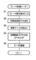
図4のブレーキ制御ルーチンは、車両の走行開始指令スイッチとしてのイグニションスイッチの信号がOFFからONに操作された後、繰返し実行される。各回の実行時には、まず、ステップS1(以下、単に「S1」で表す。他のステップについても同じ)において、ブレーキ操作値センサ12からブレーキ操作値Aが入力される。次に、S2において、その入力されたブレーキ操作値Aに基づいて目標減速度G* が決定される。ECU20のコンピュータのROMには、ブレーキ操作値Aが変化するにつれて目標減速度G* が変化する関係がテーブル,マップ等の形態で記憶されており、その関係に従い、今回のブレーキ操作値Aに対応する今回の目標減速度G* が決定される。その関係は例えば、ブレーキ操作値Aが増加するにつれてリニアに目標減速度G* が増加するように設定される。
【0040】
その後、S3において、RAMに記憶されている制御ゲインkが読み込まれる。制御ゲインkは、後述の制御ゲイン決定ルーチンにより決定されて記憶される。
【0041】
続いて、S4において、目標駆動力D* が、その読み込まれた制御ゲインkと、前記決定された目標減速度G* との積として決定される。その後、S5において、その決定された目標駆動力D* を実現するのに適当なモータ電流値が決定され、その決定された電流値でバッテリ22からモータ251に電流が供給され、それにより、モータ251が駆動される。モータ電流値の決定は、モータ駆動力センサ18により検出されたモータ駆動力Dがフィードバックされることにより行われる。以上で本ルーチンの一回の実行が終了する。
【0042】
図5の制御ゲイン決定ルーチンは、ブレーキペダル12の一連の踏込み操作(一連のブレーキ操作)が開始されることに応じて一回の実行が開始される。一回の実行が開始されると、まず、S101において、車速センサ16から車速Vが入力される。この入力された車速Vは、一連のブレーキ操作の開始時における車速Vを表している。続いて、S102において、その入力された車速Vが基準値V0 より大きいか否かが判定される。基準値V0 は例えば、ブレーキ操作値Aの時間的変化に起因しない時間的変化がブレーキ10の制動トルクTに生じると、運転者がその制動トルクTの時間的変化をブレーキ操作フィーリングの時間的変化として感じ易い車速Vの領域から感じ難い車速Vの領域への移行点を考慮して設定され、例えば、30km/hに設定される。今回は、ブレーキ操作開始時の車速Vが基準値V0 より大きくはないと仮定すれば、判定がNOとなり、S111において、制御ゲインkが、3個の候補値のうち最小の候補値cに決定されるとともに、その制御ゲインkの決定値がRAMに記憶される。今回は、低速走行中であるため、制御ゲインkをその候補値cより大きい値に決定したのでは、ブレーキ10のセルフサーボ効果によってブレーキ操作フィーリングが悪化するおそれがあるからである。以上で本ルーチンの一回の実行が終了する。
【0043】
以上、ブレーキ操作開始時の車速Vが基準値V0 より大きくはない場合を説明したが、大きい場合には、S102の判定がYESとなり、S103において、ブレーキ作動連続時間tB が測定される。ブレーキ作動連続時間tB は例えば、ブレーキペダル12が非操作位置にあればOFF、操作位置にあればONに信号が変化するストップランプスイッチ(図示しない)と、コンピュータのタイマ機能とを用い、ストップランプスイッチの信号がOFFからONに変化したときからの経過時間として取得することができる。
【0044】
なお、ブレーキ作動連続時間tB は、一連のブレーキ操作中にブレーキライニング216a,216bがドラム204に接触し続ける時間として測定するのが理想的であるが、上記のように、ストップランプスイッチを利用してブレーキ操作の連続時間として測定した場合であっても十分な測定精度が確保でき、また、この場合には安価に測定できるという利点がある。
【0045】
その後、S104において、その測定されたブレーキ作動連続時間tB が基準値tB0より長いか否かが判定される。基準値tB0の大きさは、ブレーキ10のセルフサーボ効果により、ブレーキ操作値Aの時間的変化に起因しない時間的変化が制動トルクTに現れ始める時期を考慮して設定される。今回は、ブレーキ作動連続時間tB が基準値tB0より長くはないと仮定すれば、判定がNOとなり、S110において、制御ゲインkが、3個の候補値のうち最大である候補値aに決定されるとともに、その制御ゲインkの決定値がRAMに記憶される。現時点では、ブレーキ10にセルフサーボ効果が発生していないと推定されるからである。その後、S103に戻る。
【0046】
その後、S103,S104およびS110の実行が繰り返された結果、ブレーキ作動連続時間tB が基準値tB0より長くなったと仮定すれば、S104の判定がYESとなり、S105に移行する。このS105においては、ブレーキ操作値Aの今回値A(i) から前回値A(i-1) を引き算したブレーキ操作値変化量ΔAの絶対値が基準値ΔA0 より小さい状態の連続時間tS が基準値tS0以上であるか否かが判定される。ブレーキ操作値Aが実質的に定常状態にあるか否かが判定されるのである。今回は、連続時間tS が基準値tS0以上ではないと仮定すれば、判定がNOとなり、前記の場合と同様に、S110に移行するが、基準値tS0以上であると仮定すれば、判定がYESとなり、S106に移行する。
【0047】
このS106においては、改めて車速センサ16から車速Vが入力される。ブレーキ操作開始後の車速Vが入力されるのである。その後、S107において、そのブレーキ操作開始後の車速Vが前記基準値V0 以下であるか否かが判定される。今回の一連のブレーキ操作中に、車速Vが基準値V0 より大きい値から基準値V0 と等しい値に低下したか否かが判定されるのである。今回は、ブレーキ操作開始後の車速Vが基準値V0 以下ではないと仮定すれば、判定がNOとなり、S109において、S110におけると同様に、制御ゲインkが最大の候補値aに決定されるとともに、その制御ゲインkの決定値がRAMに記憶される。その後、S105に戻る。その後、S105ないしS107およびS109の実行が何回か繰り返されるうちに、ブレーキ操作開始後の車速Vが基準値V0 以下となったと仮定すれば、S107の判定がYESとなり、S108において、制御ゲインkが、3個の候補値の中間である候補値bに決定されるとともに、その制御ゲインkの決定値がRAMに記憶される。現時点では、ブレーキ10にセルフサーボ効果が発生している可能性が高く、かつ、車両が高速走行状態から低速走行状態に移行したため、制御ゲインkを候補値bより大きい値とすると、ブレーキ10のセルフサーボ効果によってブレーキ操作フィーリングが悪化するおそれがあるからである。以上で本ルーチンの一回の実行が終了する。
【0048】
図6には、一連のブレーキ操作中に制御ゲインkを変化させない場合にブレーキ操作フィーリングが悪化することを説明するための5つのグラフが示されている。それらグラフは、車速Vが基準値V0 より大きい状態で一連のブレーキ操作が開始され、かつ、その一連のブレーキ操作中、ブレーキ操作値Aが一定とされた場合に、モータ駆動力D,制動トルクT,車体減速度Gおよび車速Vが時間tと共に変化する様子を示している。それらグラフから明らかなように、一連のブレーキ操作中に制御ゲインkを変化させない場合には、一連のブレーキ操作の末期において制動トルクTが増加し、それにより、車体減速度Gが増加し、その結果、車速Vの減少勾配が増加している。このように、運転者がブレーキペダル12を一定のブレーキ操作値Aで操作し続けるにもかかわらず、車速Vの減少勾配が時間の経過につれて増加してしまう。
【0049】
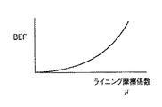
一連のブレーキ操作の末期において車体減速度Gが増加した原因としては、ブレーキ10にセルフサーボ効果を発生したことが考えられる。一方、図7には、ブレーキ10に関し、ブレーキ効力係数BEFとブレーキライニング216a,216bの摩擦係数μとの関係がグラフで表されている。
【0050】
ここで、ブレーキ効力係数BEFについて説明すると、ブレーキ効力係数BEFは、モータ駆動力Dおよび制動トルクTとの間において、
T=BEF×D
なる式で表される関係を有する。一方、モータ駆動力Dは、前述のように、目標減速度G* および制御ゲインkとの間において、
D=k×G*
なる式で表される関係を有する。したがって、ブレーキ効力係数BEFは、制動トルクTと制御ゲインkと目標減速度G* すなわちブレーキ操作値Aとの間において、
T=BEF×k×G*
なる式で表される関係を有する。
【0051】
そして、同図のグラフから明らかなように、ブレーキ10においては、摩擦係数μの増加に対するブレーキ効力係数BEFの増加率すなわちグラフの勾配が、摩擦係数μが増加するにつれて増加している。このことは、ブレーキ10の作動力すなわち制動トルクTが摩擦係数μの変化に敏感であることを表している。一方、ブレーキライニング216a,216bの摩擦係数μは、ブレーキライニング216a,216bの温度によって変化する。よって、ブレーキ効力係数BEFは、温度変化に起因した摩擦係数μの変動に対して敏感に変動する。
【0052】
そのため、ブレーキ10においては、一連のブレーキ操作中に制御ゲインkを変化させずに一定に保った場合には、セルフサーボ効果が発生してブレーキ効力係数BEFが比較的大きい値に増加した後に、温度上昇に起因した摩擦係数μの変動によって制動トルクTが敏感に変動することになる。
【0053】
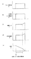
これに対して、図8には、一連のブレーキ操作中に制御ゲインkを適正に変化させる本実施形態において、車速Vが基準値V0 より大きい状態で一連のブレーキ操作が開始され、かつ、その一連のブレーキ操作中、ブレーキ操作値Aが一定とされた場合に、モータ駆動力D,制動トルクT,車体減速度Gおよび車速Vが時間tと共に変化する様子が示されている。同図の(b) のグラフから明らかなように、ブレーキ操作開始後の車速Vが基準値V0 に低下する前の期間においては、制御ゲインkが最大の候補値aに決定され、これに対して、基準値V0 に低下した後の期間においては、制御ゲインkが中間の候補値bに決定される。その結果、一連のブレーキ操作中に制御ゲインkが車速Vの低下につれて減少させられる。制御ゲインkが減少させられることは、上述のいくつかの式から明らかなように、ブレーキ効力係数BEFの変動分ΔBEFに起因した制動トルクTの変動分ΔTが減少することを意味する。その結果、同図の(c) および(d) のグラフに示すように、一連のブレーキ操作の全体において制動トルクTも車体減速度Gもほとんど変化しない。それにより、同図の(e) のグラフに示すように、車速Vがほぼ一定の勾配で減少させられることとなり、良好なブレーキ操作フィーリングが実現される。
【0054】
なお、本実施形態においては、一連のブレーキ操作中に制御ゲインkが2段階に変化させられるようになっているが、3段階以上に変化させることが可能であり、このようにすれば、制御ゲインkの変化が滑らかとなり、さらに良好なブレーキ操作フィーリングが実現される。
【0055】
図9には、本実施形態において、車速Vが基準値V0 以下である状態で一連のブレーキ操作が開始され、かつ、その一連のブレーキ操作中、ブレーキ操作値Aが一定とされた場合に、モータ駆動力D,制動トルクT,車体減速度Gおよび車速Vが時間tと共に変化する様子が示されている。この場合には、同図の(b) のグラフに示すように、一連のブレーキ操作の全体を通して、制御ゲインkが最小の候補値cに決定され、これにより、同図の(c) および(d) のグラフに示すように、制動トルクTおよび車体減速度Gがブレーキ10のセルフサーボ効果によって増加することが抑制される。その結果、同図の(e) のグラフに示すように、車速Vがほぼ一定の勾配で減少させられることとなり、良好なブレーキ操作フィーリングが実現される。
【0056】
以上の説明から明らかなように、本実施形態においては、ECU20のうち図4のブレーキ制御ルーチンを実行する部分が、ブレーキ操作値センサ12と共同して「コントローラ」を構成し、車速センサ16、ECU20のうち図5のS107ないしS109を実行する部分等が「第1の変化手段」を構成し、ECU20のうち図5のS103,S104およびS110を実行する部分等が「請求項2に記載の関係変化装置」を構成し、ECU20のうちのS104,105〜108を実行する部分等が「第2の変化手段」を構成するのである。また、ECU20のうち図5のS101,S102およびS111を実行する部分が、車速センサ18と共同して「関係設定装置」を構成しているのである。
【0057】
次に、本発明の第2実施形態を説明する。ただし、本実施形態は、第1実施形態と、制御ゲイン決定ルーチンのみが異なり、他の要素については共通であるため、共通する要素については同一の符号を使用することによって詳細な説明を省略し、異なる要素についてのみ詳細に説明する。
【0058】
第1実施形態においては、制御ゲインkがブレーキ作動連続時間tB の経過につれて減少させられるが、本実施形態においては、ブレーキ作動連続時間tB が長いほどブレーキライニング216a,216bの温度が上昇するという事実に着目することにより、その温度の上昇につれて制御ゲインkが減少させられる。
【0059】
図10には、本実施形態である電動式ブレーキ装置の全体構成が示されている。この電動式ブレーキ装置は、ECU20に相当するECU300を備えるとともに、ブレーキライニング216a,216bの一方またはそれの近傍の温度θを検出する温度センサ302を備えている。温度センサ302は、ブレーキライニング216a,216b,ブレーキシュー210a,210b,レバー230およびバッキングプレート200の少なくとも一つに装着されている。温度センサ302は例えば、サーミスタを主体として構成することができる。
【0060】
図11には、ECU300のコンピュータにより実行される制御ゲイン決定ルーチンがフローチャートで表されている。このルーチンは、図5の制御ゲイン決定ルーチンとS103およびS104においてのみ相違し、他のステップにおいては共通する。S103が置換されたS103aにおいては、温度センサ302から温度θが入力される。S104が置換されたS104aにおいては、入力された温度θが基準値θ0 より高いか否かが判定される。
【0061】
その温度θが基準値θ0 より高くはない場合には、S104aの判定がNOとなり、S110において、制御ゲインkが最大の候補値aに決定される。現時点では、ブレーキ10にセルフサーボ効果が発生していないと推定されるからである。その後、S103aに戻る。
【0062】
その後、S103a,S104aおよびS110の実行が繰り返された結果、温度θが基準値θ0 より高くなったと仮定すれば、S104aの判定がYESとなり、S105に移行する。以後の実行内容は、第1実施形態におけると同様であるため、説明を省略する。
【0063】
以上の説明から明らかなように、本実施形態においては、ECU300のうち図4のブレーキ制御ルーチンと同じものを実行する部分が、ブレーキ操作値センサ12と共同して「コントローラ」を構成し、ECU300のうち図11のS101,S102およびS107ないしS109を実行する部分等が「第1の変化手段」を構成し、同図のS103a,S104aおよびS110を実行する部分等が「請求項1に記載の関係変化装置」を構成しているのである。また、ECU300のうち図11のS101,S102およびS111を実行する部分が、車速センサ18と共同して「関係設定装置」を構成しているのである。
【0064】
次に、本発明の第3実施形態を説明する。ただし、本実施形態は、第1実施形態と制御ゲインkの変化態様のみが異なり、他の要素については共通であるため、その制御ゲインkの変化態様のみを詳細に説明し、他の要素については説明を省略する。
【0065】
第1実施形態においては、車速Vが基準値V0 より大きい状態で一連のブレーキ操作が開始された場合に、時間tの経過につれて制御ゲインkが大値aから小値bに段階的に減少させられるようになっている。これに対して、本実施形態においては、図12にグラフで示すように、制御ゲインkが連続的に変化させられる。具体的には、一連のブレーキ操作の末期において制御ゲインkが時間tの増加に対してリニアに減少するように変化させられる。したがって、本実施形態によれば、更に良好なブレーキ操作フィーリングが実現される。
【0066】
以上、本発明のいくつかの実施形態を図面に基づいて詳細に説明したが、これらは例示であり、本発明は、前記〔発明が解決しようとする課題,課題解決手段および発明の効果〕の項に記載された態様を始めとして、当業者の知識に基づいて種々の変形,改良を加えた形態で実施することができる。
【図面の簡単な説明】
【図1】本発明の第1実施形態である電動式ブレーキ装置の全体構成を示す系統図である。
【図2】図1における電動式ドラムブレーキを示す正面図である。
【図3】図2におけるシュー拡張アクチュエータを拡大して示す正面図である。
【図4】図1のECUのコンピュータにより実行されるブレーキ制御ルーチンを示すフローチャートである。
【図5】上記コンピュータにより実行される制御ゲイン決定ルーチンを示すフローチャートである。
【図6】ブレーキ操作中に制御ゲインを変化させない場合にブレーキ操作フィーリングが悪化する様子の一例を示すグラフである。
【図7】図2の電動式ドラムブレーキにおけるライニング摩擦係数μとブレーキ効力係数BEFとの関係を示すグラフである。
【図8】上記第1実施形態の作動を説明するためのグラフである。
【図9】上記第1実施形態の作動を説明するための別のグラフである。
【図10】本発明の第2実施形態である電動式ブレーキ装置を示す系統図である。
【図11】図10のECUのコンピュータにより実行される制御ゲイン決定ルーチンを示すフローチャートである。
【図12】本発明の第3実施形態である電動式ブレーキ装置において制御ゲインkが時間tの経過につれて連続的に変化させられる様子を示すグラフである。
【符号の説明】
10 電動式ドラムブレーキ
12 ブレーキペダル
14 ブレーキ操作値センサ
20,300 電子制御ユニットECU
22 バッテリ
251 DCモータ
302 温度センサ[0001]
BACKGROUND OF THE INVENTION
The present invention relates to an electric brake device for a vehicle provided with a brake using a motor as a drive source, and more particularly to an improvement in technology for controlling the drive force of the motor.
[0002]
[Prior art]
In the field of vehicle brake devices, an electric brake device that electrically operates a brake using a motor is already known. Japanese Patent Laid-Open No. 10-331876 discloses the following electric brake device. It includes (a) a brake operation member operated by a driver, such as a brake pedal, (b) a brake operation value sensor for detecting an operation value such as an operation force and an operation stroke of the brake operation member, and (c) a brake. And (d) a controller.
[0003]
The brake presses the friction material against the rotating body that rotates with the wheel by the driving force (concept including driving torque) of the motor driven by the power supplied from the power supply, thereby generating braking torque on the rotating body. The wheel is braked by the generated braking torque. There are two types of brakes: a disc type having a brake pad as a friction material and a disc as a rotating body, and a drum type having a brake lining as a friction material and a drum as a rotating body.
[0004]
The controller controls the driving force of the motor in accordance with a predetermined relationship between the operation value of the brake operation member and the driving force of the motor and based on the brake operation value detected by the brake operation value sensor. Composed.
[0005]
[Problems to be solved by the invention, problem-solving means, and effects of the invention]
In this type of electric brake device, the relationship between the motor driving force and the braking torque is not always constant and may change with time. This will be specifically described below.
[0006]
For example, when the brake is of a type that can generate a self-servo effect, such as when the brake is a normal drum type, the brake effectiveness coefficient BEF, which is the ratio at which the motor driving force is converted into the braking torque, is always constant. Not necessarily, but increases with time even if the brake operation value is constant. Therefore, when the brake is of a type that can generate a self-servo effect, a temporal change not caused by the temporal change of the brake operation value occurs in the braking torque. Therefore, in particular, as the vehicle speed decreases with the brake operation, the driver feels uncomfortable with changes in the vehicle body deceleration.
[0007]
The brake effectiveness coefficient BEF depends on the friction coefficient μ of the friction material. Specifically, the brake effectiveness coefficient BEF is changed more sensitively to changes in the friction coefficient μ of the friction material than in a small area in a large area. This is shown graphically in FIG. As a result, the braking torque is also changed more sensitively to changes in the friction coefficient μ of the friction material in a region where the brake effectiveness coefficient BEF is large than in a small region. On the other hand, the friction coefficient μ of the friction material depends on the temperature of the friction material, and the temperature of the friction material increases as the time during which the brake is continuously operated increases. For this reason, when the brake is of a type that can generate a self-servo effect, the time that does not result from the temporal change in the brake operation value due to the temporal change in the friction coefficient μ of the friction material due to the temperature change of the friction material. Changes occur in the braking torque.
[0008]
Even when the brake is of a type that does not generate a self-servo effect, such as when the brake is a normal disk type, the brake effectiveness coefficient BEF may increase with time even if the brake operation value is constant. For example, in a state where the vehicle is traveling at a low speed such as a state where the vehicle traveling speed is about 30 km / h or less, even if the brake operation value is constant, the brake effectiveness coefficient BEF may increase with time. is there. This is expected to be caused by the friction material biting into the rotating body. Therefore, even when the brake does not generate the self-servo effect, a temporal change not caused by the temporal change of the brake operation value may occur in the braking torque.
[0009]
The occurrence of a temporal change in the braking torque that does not result from a temporal change in the brake operation value causes a driver's brake operation feeling to deteriorate regardless of the type of the cause. Therefore, in the electric brake device, if the motor driving force is controlled without considering such a temporal change of the braking torque, the brake operation feeling may be deteriorated.
[0010]
Against this background, the present invention has been made with the object of optimizing the motor driving force in relation to the brake operation value, and the following aspects are obtained by the present invention. As with the claims, each aspect is divided into sections, each section is numbered, and is described in a form that cites the numbers of other sections as necessary. This is to facilitate understanding of some of the technical features and combinations thereof described herein, and the technical features and combinations thereof described herein are limited to the following aspects. Should not be interpreted.
[0011]
(1) a brake operation member operated by a driver;
A brake operation value sensor for detecting an operation value that is an operation force or an operation stroke of the brake operation member;
The friction material is pressed against the rotating body that rotates with the wheel by the driving force of the motor driven by electric power, thereby generating braking torque on the rotating body, and braking the wheel by the generated braking torque.Can generate a self-servo effectBrakes,
A controller that controls the driving force of the motor according to a predetermined relationship between the operation value of the brake operation member and the driving force of the motor and based on the brake operation value detected by the brake operation value sensor;
In the electric brake device including
A temperature sensor for detecting the temperature of the friction material;
During a series of brake operations, the temperature detected by the temperature sensor is high.The braking effectiveness coefficient, which is a value obtained by dividing the braking torque by the motor driving force,Due to the change in the friction coefficient of the friction materialIf it is in the temperature range that can be greatly changed,The temperature is low,Of the brake effectiveness factorSmall change due to change in friction coefficient of the friction materialtemperatureA relationship change device that changes the relationship so that the driving force of the motor corresponding to the same brake operation value is smaller than in the region
An electric brake device comprising:
(2) a brake operating member operated by the driver;
A brake operation value sensor for detecting an operation value that is an operation force or an operation stroke of the brake operation member;
A brake that presses the friction material against a rotating body that rotates together with the wheel by a driving force of a motor driven by electric power, thereby generating braking torque on the rotating body, and braking the wheel by the generated braking torque; ,
A controller that controls the driving force of the motor according to a predetermined relationship between the operation value of the brake operation member and the driving force of the motor and based on the brake operation value detected by the brake operation value sensor;
In the electric brake device including
During a series of brake operations, the change in the coefficient of friction of the friction material increases as the temperature of the friction material increases during the brake operation continuous time in which the brake operation continues.Even if the brake operation value is constant, the braking torque starts to change with the change of the friction coefficient of the friction material.An electric motor comprising a relationship changing device that changes the relationship so that the driving force of the motor corresponding to the same brake operation value becomes smaller before the reference time, which is a time, is exceeded. Brake device (claim 2).
According to this electric brake device, the relationship is not constant during a series of brake operations, but is changed during a series of brake operations. According to this electric brake device, the relationship can be changed during a series of brake operations so that a temporal change not caused by a temporal change in the brake operation value does not substantially occur in the braking torque. It is. Therefore, according to this electric brake device, the motor driving force can be optimized in relation to the brake operation value, and as a result, a good brake operation feeling can be obtained.
In this electric brake device, for the “change the relationship during a series of brake operations”, select a format that changes the relationship once in the course of a series of brake operations, or a format that changes multiple times. be able to. It can be said that the type that changes once is a type that changes the relationship in two stages during a series of brake operations, and the type that changes a plurality of times is that the relationship is changed over three levels during a series of brake operations. It can be said that it is a form to change to.
In this electric brake device, “a series of brake operations” refers to the operation of the driver from the start of the operation of the brake operation member to the first end of the operation.
In this electric brake device, the technique of “changing the relationship” is a technique in which the power value supplied to the motor (hereinafter referred to as “motor power value”) and the motor driving force are in a one-to-one correspondence. In the process of determining the motor power value according to the operation value, it can be realized as a technology that changes the relationship between the brake operation value and the motor power value, and the vehicle deceleration target value is determined according to the brake operation value. In the process of determining the motor power value according to the target deceleration, this can be realized as a technique for changing the relationship between the brake operation value and the target deceleration. Further, when the relationship between the motor power value and the motor driving force can be changed electrically or mechanically, it can be realized as a technique for changing the relationship.
In this electric brake device, the brake can be a drum type or a disk type. Further, the disc type brake can be of a type that can generate a self-servo effect or a type that does not.
In the electric brake device, the “relation” is a continuous relationship (for example, a pattern) indicating that the motor driving force increases as the brake operation value increases, or the brake operation value and the motor driving force at a certain moment. Relationship can be.
In the electric brake device described in the item (1), the temperature of the friction material is detected during a series of brake operations, and the relationship is changed in consideration of the temperature. When it is desirable to reduce the motor driving force because the temperature of the friction material or the like is high, the motor driving force is reduced, thereby suppressing the change in the braking torque, thereby improving the brake operation feeling. Moreover, according to this electric brake device, the temperature is detected during a series of brake operations. Therefore, it becomes easy to change the relationship in real time so as to accurately follow the change in temperature, and as a result, the control accuracy of the motor driving force can be easily improved.
In the electric brake device described in (2), the temperature of the friction material or the vicinity thereof increases as the brake operation continuous time elapses. Between the brake operation continuous time and the temperature of the friction material, etc. A certain relationship is established. Therefore, if it is desirable to reduce the motor driving force because the brake operation continuous time is long, if the motor driving force is reduced, a change in braking torque can be suppressed, and the brake operation feeling can be improved. . Moreover, according to this electric brake device, the motor driving force can be optimized in relation to the brake operation value.
( 3 )In the case where the relation change device has a low braking speed when the brake operation continuous time exceeds the reference time and the brake operation member is in a steady operation state, the vehicle traveling speed or the wheel rotational speed is small. Item (2) includes second changing means for changing the relationship so that the driving force of the motor corresponding to the same brake operation value is smaller than when the brake operation value is large.InElectric brake device according to claim3).
( 4 )The relationship change device is configured so that the driving force of the motor corresponding to the same brake operation value is smaller when the vehicle traveling speed or wheel rotation speed during a series of brake operations is small than when the speed is large. (1) including first changing means for changingOr (3) Any one of the termsElectric brake device according to claim4).
As described above, the friction material is more likely to bite against the rotating body than when the vehicle traveling speed or the wheel rotational speed is large, and therefore, the braking torque that is not caused by the time increase of the brake operation value is increased. There is a high possibility that a time increase will occur.
Further, the driver can easily perceive the temporal change of the braking torque not caused by the temporal change of the brake operation value as the temporal change of the brake operation feeling, as compared with the case where the vehicle travel speed is small and large. There is a high need to suppress temporal changes in braking torque that are not caused by temporal changes in brake operation values.
In addition, prevention of deterioration of the brake operation feeling is a strongly demanded matter when the vehicle traveling speed is small, whereas the increase in braking effectiveness is small when the vehicle traveling speed is large. This is considered to be a strongly requested matter in some cases. On the other hand, the time increase of the braking torque not caused by the time increase of the brake operation value means that the effectiveness of the brake is increased. Therefore, when the vehicle traveling speed is high, priority is given to increasing the braking effect, while when the vehicle traveling speed is low, priority can be given to preventing the deterioration of the brake operation feeling. It is more appropriate to suppress the time increase of the braking torque that is not caused by the time increase of the brake operation value than when the vehicle travel speed is low and high.
In the electric brake device described in this section, when it is desirable to reduce the motor driving force because the traveling speed of the vehicle or the rotational speed of the wheels is small, the change in the braking torque is reduced by reducing the motor driving force. Therefore, the brake operation feeling is improved.
( 5 )When the first change means has a higher motor driving force corresponding to the same brake operation value than when the brake operation start speed, which is the speed at the start of a series of brake operations, is smaller than the first reference value. Including means for setting the relationship to be smaller(FourThe electric brake device according to the item).
According to this electric brake device, the relationship is set to be different between when the brake operation start speed is low and when the brake operation start speed is high, and as a result, the motor driving force is optimized in relation to the brake operation start speed. Is done.
( 6 )When the first change means has the brake operation start speed larger than the first reference value, the motor driving force corresponding to the same brake operation value is the speed after the start of the series of brake operations. And means for changing the relationship so that the speed after the start of a certain brake operation becomes smaller in the period before the decrease in the period after the decrease in the second reference value.(FiveThe electric brake device according to the item).
According to this electric brake device, the relationship is changed as the speed after the start of the brake operation changes, and as a result, the motor driving force is related to the brake operation value by considering the speed after the start of the brake operation. Can be optimized.
In this electric brake device, the “second reference value” can be equal to or different from the first reference value.
( 7 )The relationship changing device includes fourth changing means for changing the relationship based on whether or not the brake operation value is in a steady state in which a temporal change does not substantially occur (1) to(6)The electric brake device according to any one of the items.
The driver feels that the brake operation time change is not caused by the time change of the brake operation value in the steady state where the time change of the brake operation value does not substantially occur than in the non-steady state where the brake operation value does not substantially change. It is easy to feel as time changes.
Based on such knowledge, in the electric brake device described in this section, the relationship is changed based on whether or not the brake operation value is in a steady state.
( 8 )The fourth changing means includes means for changing the relationship so that a motor driving force corresponding to the same brake operation value becomes smaller in the steady state than in the unsteady state.(7)The electric brake device according to item.
According to this electric brake device, the motor driving force is reduced in the steady state of the brake operation value where the driver can easily feel the temporal change of the braking torque, so that the amount of change in the braking torque is reduced. The deterioration of the brake operation feeling is suppressed.
(9) The relationship is related to the brake operation value.The value multiplied by the coefficient isTarget value of the driving force of the motorIsRelationship,The relationship changing device includes means for changing the relationship by changing the coefficient.The electric brake device according to any one of (1) to (8) (claim 5).
Here, the “control gain” can be common to the entire changeable region of the brake operation value, or can be changed according to the brake operation value.
(10) The relationship changing device changes the relationship during a series of brake operations so that a temporal change not caused by a temporal change in the brake operation value does not substantially occur in the braking torque. The electric brake device according to any one of (1) to (9).
According to this electric brake device, the relationship is changed during a series of brake operations so that a temporal change not caused by a temporal change in the brake operation value does not substantially occur in the braking torque. Therefore, according to this electric brake device, a good brake operation feeling can be obtained.
(11) The relationship changing device may change a vehicle traveling speed or a wheel rotational speed during a series of brake operations, a lapse of a brake operation continuous time during which the brake operation continues during a series of brake operations, Changes in temperature indicating the temperature of the friction material or its surroundings during the brake operation of the vehicle and changes in information indicating whether or not the brake operation value is in a steady state during the series of brake operations. The electric brake device according to any one of (1) to (10), wherein the relationship is changed in relation to at least one of
(12) The electric brake device according to any one of (1) to (11), wherein the relationship changing device changes the relationship stepwise.
The relationship change device can be implemented in a manner that changes the relationship substantially continuously, but if implemented in a manner that changes stepwise, it is implemented in a manner that changes substantially continuously. Compared with the case where it does, the structure for changing the said relationship, for example, the load of a computer program, memory, etc., is reduced.
(13) The relationship changing device includes a possibility determining means for determining whether or not a temporal change not caused by a temporal change in the brake operation value may occur in the braking torque, and the possibility determining means The electric brake device according to any one of (1) to (12), wherein the relationship is changed when it is determined that there is a possibility.
Here, the “possibility determining means” means that, for example, the possibility that a temporal change not caused by the temporal change of the brake operation value is generated in the braking torque is higher in the case where the brake operation is continued for a long time and in the short case. By paying attention to the fact, it is possible to determine whether or not the possibility exists, and there is a possibility that a temporal change not caused by a temporal change in the brake operation value will occur in the braking torque. By paying attention to the fact that it is higher in the low case than in the low case, the possibility can be made a format for determining the presence or absence.
(14) Whether the relationship changing device further needs to change the relationship so that a temporal change not caused by a temporal change in the brake operation value does not substantially occur in the braking torque. The necessity determination means determines that there is a possibility that a temporal change not caused by a temporal change in the brake operation value may occur in the braking torque, and the necessity If the determination means determines that it is necessary to change the relationship so that a temporal change not caused by a temporal change in the brake operation value does not substantially occur in the braking torque, the relationship is changed. The electric brake device according to item (13).
Here, the “necessity determining means” means that, for example, when a temporal change not caused by the temporal change of the brake operation value occurs in the braking torque, the driver shows the temporal change of the braking torque when the vehicle traveling speed is low. Whether it is necessary to change the relationship so that a temporal change not caused by a temporal change of the brake operation value does not substantially occur in the braking torque by focusing on the fact that it is easier to feel in the case of high It can be a format for determining whether or not. In addition, when a temporal change not caused by a temporal change in the brake operation value occurs in the braking torque, the driver feels the temporal change in the braking torque more than in a case where there is no temporal change in the brake operation value. Focusing on the fact that it is easy to determine whether it is necessary to change the relationship so that a temporal change not caused by a temporal change in the brake operation value does not substantially occur in the braking torque You can also
(15) In the case where the electric brake device further has a small brake operation start speed which is a vehicle traveling speed or a wheel rotation speed at the start of each series of brake operations for each series of brake operations. Includes a relationship setting device for changing the relationship so that the driving force of the motor corresponding to the same brake operation value is smaller than when it is large, the electric type according to any one of items (1) to (14) Brake device (Claim 6).
When determining whether the speed at which the brake operation is started is a type in which a series of brake operations is a type in which the driver is likely to feel a change in braking torque or a type in which it is difficult, I realized that it was an effective parameter to consider.
Based on such knowledge, the relationship is set based on the brake operation start speed in the electric brake device described in this section. Therefore, according to this electric brake device, the motor driving force is optimized in relation to the brake operation value regardless of the type of a series of brake operations, and as a result, a good brake operation feeling can be obtained. . In addition, it is possible to prevent the brake operation feeling from deteriorating during low-speed traveling where the driver can easily feel the change in braking torque.
(16) a brake operation member operated by the driver;
A brake operation value sensor for detecting an operation value of the brake operation member;
A brake that presses the friction material against a rotating body that rotates together with the wheel by a driving force of a motor driven by electric power, thereby generating braking torque on the rotating body, and braking the wheel by the generated braking torque; ,
A controller that controls the driving force of the motor according to a predetermined relationship between the operation value of the brake operation member and the driving force of the motor and based on the brake operation value detected by the brake operation value sensor;
In the electric brake device including
Steady state in which a temporal change does not substantially occur in a speed that is a traveling speed of a vehicle or a rotational speed of a wheel, a time during which the operation of the brake is continued, a temperature of the friction material or its surroundings, and a brake operation value. An electric brake device comprising a relationship determining device that determines the relationship based on at least one of information indicating whether or not the vehicle is in a state.
In this electric brake device, the term “determining the relationship” means that the initial value of the relationship is set for each series of brake operations and the relationship is changed during each series of brake operations. And at least one of them.
[0012]
DETAILED DESCRIPTION OF THE INVENTION
Hereinafter, some of more specific embodiments of the present invention will be described in detail with reference to the drawings.
[0013]
FIG. 1 shows the overall configuration of the electric brake device according to the first embodiment of the present invention. This electric brake device is provided in a four-wheel vehicle provided with left and right front wheels FL and FR and left and right rear wheels RL and RR. The left and right front wheels FL, FR are provided with electric disc brakes that use an ultrasonic motor as a drive source and do not use fluid pressure. On the other hand, the left and right rear wheels RL and RR are provided with electric drum brakes that use a DC motor as a drive source and do not use fluid pressure. However, since it is the electric drum brake that is particularly necessary to understand the present invention through the present embodiment, the electric drum brake (one of the left and right rear wheels) is shown in FIG. Only 10) (hereinafter simply referred to as “brake”) is representatively shown.
[0014]
In addition to the
[0015]
The electric brake device further includes a
[0016]
The electric brake device further includes an electronic control unit (hereinafter abbreviated as “ECU”) 20 and a
[0017]
FIG. 2 shows the
[0018]
The
[0019]
An
[0020]
The pair of
[0021]
Each of the
[0022]
As is apparent from the above description, the
[0023]
One end of the
[0024]
The
[0025]
The coupling between the
[0026]
The
[0027]
The
[0028]
The motor driving
[0029]
The motor driving
[0030]
The
[0031]
Based on the brake operation value A, the
[0032]
The
D*= K × G*
It is determined using the following formula.
[0033]
Target deceleration G*Is a value corresponding to the brake operation value A, and means an input to the
[0034]
The
[0035]
Regarding the technique for setting the initial value of the control gain k, the
[0036]
Regarding the technique for changing the control gain k, the
[0037]
Regarding the technique of changing the control gain k, the
a> b> c
It is expressed by the following formula.
[0038]
Next, the brake control will be specifically described with reference to the flowcharts of FIGS.
[0039]
The brake control routine of FIG. 4 is repeatedly executed after the signal of the ignition switch as the vehicle travel start command switch is operated from OFF to ON. In each execution, first, in step S1 (hereinafter, simply referred to as “S1”, the same applies to other steps), the brake operation value A is input from the brake
[0040]
Thereafter, in S3, the control gain k stored in the RAM is read. The control gain k is determined and stored by a later-described control gain determination routine.
[0041]
Subsequently, in S4, the target driving force D*Is the read control gain k and the determined target deceleration G*And the product of Thereafter, in S5, the determined target driving force D*A motor current value suitable for realizing the above is determined, and a current is supplied from the
[0042]
The control gain determination routine of FIG. 5 is executed once in response to the start of a series of depression operations (a series of brake operations) of the
[0043]
As described above, the vehicle speed V at the start of the brake operation is the reference value V.0Although the case where it is not larger has been described, if it is larger, the determination in S102 is YES, and in S103, the brake operation continuous time tBIs measured. Brake operation continuous time tBFor example, a stop lamp switch (not shown) whose signal changes to ON when the
[0044]
In addition, brake operation continuous time tBIs ideally measured as the time during which the
[0045]
Then, in S104, the measured brake operation continuous time tBIs the reference value tB0It is determined whether it is longer. Reference value tB0Is set in consideration of the time when a temporal change not caused by the temporal change of the brake operation value A starts to appear in the braking torque T due to the self-servo effect of the
[0046]
Thereafter, as a result of repeating the execution of S103, S104, and S110, the brake operation continuous time tBIs the reference value tB0If it is assumed that the length is longer, the determination in S104 is YES, and the process proceeds to S105. In S105, the current value A of the brake operation value A(i)To previous value A(i-1)The absolute value of the brake operation value change ΔA obtained by subtracting the value is the reference value ΔA0Continuous time t in smaller stateSIs the reference value tS0It is determined whether or not this is the case. It is determined whether or not the brake operation value A is substantially in a steady state. This time, continuous time tSIs the reference value tS0If it is assumed that it is not above, the determination is NO and the process proceeds to S110 as in the above case, but the reference value tS0If it is assumed that the above is true, the determination is YES, and the process proceeds to S106.
[0047]
In S106, the vehicle speed V is input again from the
[0048]
FIG. 6 shows five graphs for explaining that the brake operation feeling deteriorates when the control gain k is not changed during a series of brake operations. These graphs show that the vehicle speed V is the reference value V0When a series of brake operations are started in a larger state and the brake operation value A is constant during the series of brake operations, the motor driving force D, braking torque T, vehicle deceleration G, and vehicle speed V are It shows how it changes with time t. As is apparent from these graphs, when the control gain k is not changed during a series of brake operations, the braking torque T increases at the end of the series of brake operations, thereby increasing the vehicle body deceleration G. As a result, the decreasing gradient of the vehicle speed V is increasing. Thus, although the driver continues to operate the
[0049]
As a cause of the increase in the vehicle body deceleration G at the end of a series of brake operations, it can be considered that the self-servo effect is generated in the
[0050]
Here, the brake effectiveness coefficient BEF will be described. The brake effectiveness coefficient BEF is between the motor driving force D and the braking torque T.
T = BEF × D
It has a relationship expressed by the following formula. On the other hand, the motor driving force D is the target deceleration G as described above.*And the control gain k,
D = k × G*
It has a relationship expressed by the following formula. Therefore, the brake effectiveness coefficient BEF is determined by the braking torque T, the control gain k, and the target deceleration G*That is, between the brake operation value A and
T = BEF × k × G*
It has a relationship expressed by the following formula.
[0051]
As is apparent from the graph of FIG. 10, in the
[0052]
Therefore, in the
[0053]
On the other hand, FIG. 8 shows that the vehicle speed V is the reference value V in this embodiment in which the control gain k is appropriately changed during a series of brake operations.0When a series of brake operations are started in a larger state and the brake operation value A is constant during the series of brake operations, the motor driving force D, braking torque T, vehicle deceleration G, and vehicle speed V are It is shown that it changes with time t. As is apparent from the graph (b) in the figure, the vehicle speed V after the start of the brake operation is the reference value V0In the period before it decreases to the control value k, the control gain k is determined to be the maximum candidate value a.0In the period after the decrease, the control gain k is determined to be an intermediate candidate value b. As a result, the control gain k is decreased as the vehicle speed V decreases during a series of brake operations. The fact that the control gain k is decreased means that the variation ΔT of the braking torque T caused by the variation ΔBEF of the brake effectiveness coefficient BEF decreases, as is apparent from the above-mentioned several equations. As a result, as shown in the graphs (c) and (d) of the figure, the braking torque T and the vehicle body deceleration G hardly change during the entire series of braking operations. As a result, as shown in the graph of (e) in the figure, the vehicle speed V is reduced with a substantially constant gradient, and a good brake operation feeling is realized.
[0054]
In the present embodiment, the control gain k can be changed in two stages during a series of brake operations, but it can be changed in three stages or more. The change in the gain k becomes smooth and a better brake operation feeling is realized.
[0055]
In FIG. 9, in this embodiment, the vehicle speed V is the reference value V.0When a series of brake operations are started in the following conditions and the brake operation value A is constant during the series of brake operations, the motor driving force D, the braking torque T, the vehicle body deceleration G, and the vehicle speed V Is shown to change with time t. In this case, as shown in the graph of (b) in the same figure, the control gain k is determined to be the minimum candidate value c throughout the series of brake operations, whereby (c) and (c) in FIG. As shown in the graph of d), increase of the braking torque T and the vehicle body deceleration G due to the self-servo effect of the
[0056]
As is clear from the above description, in this embodiment, the part of the
[0057]
Next, a second embodiment of the present invention will be described. However, the present embodiment is different from the first embodiment only in the control gain determination routine, and the other elements are common, and therefore, the detailed description is omitted by using the same reference numerals for the common elements. Only the different elements will be described in detail.
[0058]
In the first embodiment, the control gain k is equal to the brake operation continuous time t.BIn this embodiment, the brake operation continuous time t is decreased.BBy paying attention to the fact that the temperature of the
[0059]
FIG. 10 shows the overall configuration of the electric brake device according to the present embodiment. The electric brake device includes an
[0060]
FIG. 11 is a flowchart showing a control gain determination routine executed by the computer of
[0061]
The temperature θ is the reference value θ0If it is not higher, the determination in S104a is NO, and in S110, the control gain k is determined to be the maximum candidate value a. This is because it is estimated that no self-servo effect is generated in the
[0062]
Then, as a result of repeating the execution of S103a, S104a and S110, the temperature θ becomes the reference value θ.0If it is assumed that it has become higher, the determination in S104a is YES, and the process proceeds to S105. Since the subsequent execution contents are the same as those in the first embodiment, description thereof will be omitted.
[0063]
As is apparent from the above description, in the present embodiment, a portion of the
[0064]
Next, a third embodiment of the present invention will be described. However, since this embodiment is different from the first embodiment only in the change mode of the control gain k, and the other elements are common, only the change mode of the control gain k will be described in detail, and the other elements will be described. Will not be described.
[0065]
In the first embodiment, the vehicle speed V is the reference value V.0When a series of brake operations are started in a larger state, the control gain k is gradually decreased from the large value a to the small value b as time t elapses. On the other hand, in the present embodiment, as shown by a graph in FIG. 12, the control gain k is continuously changed. Specifically, at the end of a series of brake operations, the control gain k is changed so as to decrease linearly with an increase in time t. Therefore, according to this embodiment, a better brake operation feeling is realized.
[0066]
As mentioned above, although several embodiment of this invention was described in detail based on drawing, these are illustrations, and this invention is the above-mentioned [the subject which invention intends to solve, a problem-solving means, and the effect of invention]. The embodiment described in the section can be implemented with various modifications and improvements based on the knowledge of those skilled in the art.
[Brief description of the drawings]
FIG. 1 is a system diagram showing an overall configuration of an electric brake device according to a first embodiment of the present invention.
FIG. 2 is a front view showing the electric drum brake in FIG. 1;
FIG. 3 is an enlarged front view showing a shoe extension actuator in FIG. 2;
4 is a flowchart showing a brake control routine executed by a computer of the ECU shown in FIG. 1. FIG.
FIG. 5 is a flowchart showing a control gain determination routine executed by the computer.
FIG. 6 is a graph showing an example of how the brake operation feeling deteriorates when the control gain is not changed during the brake operation.
7 is a graph showing a relationship between a lining friction coefficient μ and a brake effectiveness coefficient BEF in the electric drum brake of FIG. 2;
FIG. 8 is a graph for explaining the operation of the first embodiment.
FIG. 9 is another graph for explaining the operation of the first embodiment.
FIG. 10 is a system diagram showing an electric brake device according to a second embodiment of the present invention.
11 is a flowchart showing a control gain determination routine executed by a computer of the ECU shown in FIG.
FIG. 12 is a graph showing how the control gain k is continuously changed over time in the electric brake device according to the third embodiment of the present invention.
[Explanation of symbols]
10 Electric drum brake
12 Brake pedal
14 Brake operation value sensor
20,300 Electronic control unit ECU
22 battery
251 DC motor
302 Temperature sensor
Claims (6)
そのブレーキ操作部材の操作力または操作ストロークである操作値を検出するブレーキ操作値センサと、
電力により駆動されるモータの駆動力により摩擦材を、車輪と共に回転する回転体に押し付け、それにより、その回転体に制動トルクを発生させ、その発生させられた制動トルクにより車輪を制動し、セルフサーボ効果を発生可能なブレーキと、
前記ブレーキ操作部材の操作値と前記モータの駆動力との間の予め定められた関係に従い、かつ、前記ブレーキ操作値センサにより検出されたブレーキ操作値に基づき、モータの駆動力を制御するコントローラと
を含む電動式ブレーキ装置において、
前記摩擦材の温度を検出する温度センサと、
一連のブレーキ操作中において、前記温度センサにより検出された温度が高く、前記制動トルクをモータ駆動力で割った値であるブレーキ効力係数が、前記摩擦材の摩擦係数の変化に起因して大きく変化させられる温度領域にある場合には、前記温度が低く、前記ブレーキ効力係数の前記摩擦材の摩擦係数の変化に起因する変化が小さい温度領域にある場合より、同じブレーキ操作値に対応する前記モータの駆動力が小さくなるように前記関係を変化させる関係変化装置と
を含むことを特徴とする電動式ブレーキ装置。A brake operating member operated by the driver;
A brake operation value sensor for detecting an operation value that is an operation force or an operation stroke of the brake operation member;
The friction material is pressed against the rotating body that rotates together with the wheel by the driving force of the motor driven by electric power, thereby generating a braking torque on the rotating body, braking the wheel by the generated braking torque , and self- A brake capable of generating a servo effect ;
A controller that controls the driving force of the motor according to a predetermined relationship between the operation value of the brake operation member and the driving force of the motor and based on the brake operation value detected by the brake operation value sensor; In the electric brake device including
A temperature sensor for detecting the temperature of the friction material;
During a series of braking operations, the temperature detected by the temperature sensor is high , and the braking effectiveness coefficient, which is a value obtained by dividing the braking torque by the motor driving force, greatly changes due to a change in the friction coefficient of the friction material. the motor case, the temperature is low, the more the case where changes due to changes in the friction coefficient of the friction material of the brake effectiveness coefficient is small temperature range, corresponding to the same brake operation value in the temperature region provoking And a relationship change device that changes the relationship so that the driving force of the motor is reduced.
そのブレーキ操作部材の操作力または操作ストロークである操作値を検出するブレーキ操作値センサと、
電力により駆動されるモータの駆動力により摩擦材を、車輪と共に回転する回転体に押し付け、それにより、その回転体に制動トルクを発生させ、その発生させられた制動トルクにより車輪を制動するブレーキと、
前記ブレーキ操作部材の操作値と前記モータの駆動力との間に予め定められた関係に従い、かつ、前記ブレーキ操作値センサにより検出されたブレーキ操作値に基づき、モータの駆動力を制御するコントローラと
を含む電動式ブレーキ装置において、
一連のブレーキ操作中において、前記ブレーキの作動が連続するブレーキ作動連続時間が、前記摩擦材の温度が高くなることにより摩擦材の摩擦係数の変化が大きくなり、前記ブレーキ操作値が一定であっても、前記摩擦材の摩擦係数の変化に伴って制動トルクが変化し始める時間である基準時間を超えた場合には、越える以前より、同じブレーキ操作値に対応する前記モータの駆動力が小さくなるように前記関係を変化させる関係変化装置を設けたことを特徴とする電動式ブレーキ装置。A brake operating member operated by the driver;
A brake operation value sensor for detecting an operation value that is an operation force or an operation stroke of the brake operation member;
A brake that presses the friction material against a rotating body that rotates together with the wheel by a driving force of a motor driven by electric power, thereby generating braking torque on the rotating body, and braking the wheel by the generated braking torque; ,
A controller that controls the driving force of the motor according to a predetermined relationship between the operation value of the brake operation member and the driving force of the motor and based on the brake operation value detected by the brake operation value sensor; In the electric brake device including
During a series of brake operations, the brake operation continuous time during which the brake operation continues is performed, the change in the friction coefficient of the friction material increases as the temperature of the friction material increases, and the brake operation value is constant. However, when the reference time, which is the time when the braking torque starts to change with the change of the friction coefficient of the friction material , is exceeded, the driving force of the motor corresponding to the same brake operation value becomes smaller than before the time is exceeded. As described above, an electric brake device characterized in that a relationship changing device for changing the relationship is provided.
Priority Applications (1)
| Application Number | Priority Date | Filing Date | Title |
|---|---|---|---|
| JP06823699A JP3736183B2 (en) | 1999-03-15 | 1999-03-15 | Electric brake device |
Applications Claiming Priority (1)
| Application Number | Priority Date | Filing Date | Title |
|---|---|---|---|
| JP06823699A JP3736183B2 (en) | 1999-03-15 | 1999-03-15 | Electric brake device |
Publications (2)
| Publication Number | Publication Date |
|---|---|
| JP2000264183A JP2000264183A (en) | 2000-09-26 |
| JP3736183B2 true JP3736183B2 (en) | 2006-01-18 |
Family
ID=13367963
Family Applications (1)
| Application Number | Title | Priority Date | Filing Date |
|---|---|---|---|
| JP06823699A Expired - Fee Related JP3736183B2 (en) | 1999-03-15 | 1999-03-15 | Electric brake device |
Country Status (1)
| Country | Link |
|---|---|
| JP (1) | JP3736183B2 (en) |
Families Citing this family (8)
| Publication number | Priority date | Publication date | Assignee | Title |
|---|---|---|---|---|
| JP4844860B2 (en) * | 2001-05-31 | 2011-12-28 | 日立オートモティブシステムズ株式会社 | Adaptive cruise control system |
| JP4756230B2 (en) * | 2001-09-28 | 2011-08-24 | 日立オートモティブシステムズ株式会社 | Electric brake device |
| JP4928085B2 (en) * | 2004-06-30 | 2012-05-09 | 株式会社ハイレックスコーポレーション | Electric brake device |
| JP4928080B2 (en) * | 2004-06-30 | 2012-05-09 | 株式会社ハイレックスコーポレーション | Electric cable drive device and electric brake device |
| FR2883241B1 (en) | 2005-03-15 | 2007-06-08 | Renault Sas | METHOD FOR MANAGING BRAKE INFORMATION |
| JP5453752B2 (en) * | 2008-09-24 | 2014-03-26 | 日産自動車株式会社 | Braking force control device |
| JP5997565B2 (en) * | 2012-09-28 | 2016-09-28 | 日立オートモティブシステムズ株式会社 | Brake control device |
| JP7285230B2 (en) * | 2020-03-31 | 2023-06-01 | 株式会社アドヴィックス | Braking control device |
-
1999
- 1999-03-15 JP JP06823699A patent/JP3736183B2/en not_active Expired - Fee Related
Also Published As
| Publication number | Publication date |
|---|---|
| JP2000264183A (en) | 2000-09-26 |
Similar Documents
| Publication | Publication Date | Title |
|---|---|---|
| US6425643B2 (en) | Electrically operated braking system having a device for operating electric motor of brake to obtain relationship between motor power and braking torque | |
| US6607253B1 (en) | Braking torque control apparatus and method | |
| JP4265634B2 (en) | Electric parking brake system | |
| JP4470928B2 (en) | Electric parking brake system | |
| JP4265633B2 (en) | Electric parking brake system | |
| US7140697B2 (en) | Electric parking brake apparatus | |
| EP1253056B1 (en) | Method and apparatus for diagnosing electrically operated brake | |
| JP3736183B2 (en) | Electric brake device | |
| JP2000033864A (en) | Method for controlling brake unit and apparatus for same | |
| JP2008068835A (en) | Electric parking brake system | |
| JP4191871B2 (en) | Brake device | |
| JP2001080496A (en) | Electric brake system | |
| WO2020066645A1 (en) | Electric brake, and control device | |
| JP4600133B2 (en) | Parking brake equipment | |
| JP2003104195A (en) | Electric brake device | |
| JP4298837B2 (en) | Electric brake device | |
| JP5228306B2 (en) | Electric parking brake system | |
| JP3740800B2 (en) | Electric brake device | |
| JP4109741B2 (en) | Electric brake | |
| JP2000203402A (en) | Brake control device | |
| JP4222348B2 (en) | Electric brake abnormality judgment method | |
| JP4240055B2 (en) | Electric brake | |
| JP2004239324A (en) | Pad clearance adjusting method for electric disk brake | |
| JP2016043845A (en) | Braking system of vehicle | |
| JP3911807B2 (en) | Brake system |
Legal Events
| Date | Code | Title | Description |
|---|---|---|---|
| A977 | Report on retrieval |
Free format text: JAPANESE INTERMEDIATE CODE: A971007 Effective date: 20050118 |
|
| A131 | Notification of reasons for refusal |
Free format text: JAPANESE INTERMEDIATE CODE: A131 Effective date: 20050125 |
|
| A521 | Written amendment |
Free format text: JAPANESE INTERMEDIATE CODE: A523 Effective date: 20050325 |
|
| A131 | Notification of reasons for refusal |
Free format text: JAPANESE INTERMEDIATE CODE: A131 Effective date: 20050607 |
|
| A521 | Written amendment |
Free format text: JAPANESE INTERMEDIATE CODE: A523 Effective date: 20050720 |
|
| TRDD | Decision of grant or rejection written | ||
| A01 | Written decision to grant a patent or to grant a registration (utility model) |
Free format text: JAPANESE INTERMEDIATE CODE: A01 Effective date: 20051004 |
|
| A61 | First payment of annual fees (during grant procedure) |
Free format text: JAPANESE INTERMEDIATE CODE: A61 Effective date: 20051017 |
|
| R150 | Certificate of patent or registration of utility model |
Free format text: JAPANESE INTERMEDIATE CODE: R150 |
|
| FPAY | Renewal fee payment (event date is renewal date of database) |
Free format text: PAYMENT UNTIL: 20081104 Year of fee payment: 3 |
|
| FPAY | Renewal fee payment (event date is renewal date of database) |
Free format text: PAYMENT UNTIL: 20091104 Year of fee payment: 4 |
|
| FPAY | Renewal fee payment (event date is renewal date of database) |
Free format text: PAYMENT UNTIL: 20101104 Year of fee payment: 5 |
|
| FPAY | Renewal fee payment (event date is renewal date of database) |
Free format text: PAYMENT UNTIL: 20111104 Year of fee payment: 6 |
|
| FPAY | Renewal fee payment (event date is renewal date of database) |
Free format text: PAYMENT UNTIL: 20121104 Year of fee payment: 7 |
|
| FPAY | Renewal fee payment (event date is renewal date of database) |
Free format text: PAYMENT UNTIL: 20121104 Year of fee payment: 7 |
|
| FPAY | Renewal fee payment (event date is renewal date of database) |
Free format text: PAYMENT UNTIL: 20131104 Year of fee payment: 8 |
|
| LAPS | Cancellation because of no payment of annual fees |