JP3734026B2 - Oil strainer manufacturing method - Google Patents
Oil strainer manufacturing method Download PDFInfo
- Publication number
- JP3734026B2 JP3734026B2 JP2001339151A JP2001339151A JP3734026B2 JP 3734026 B2 JP3734026 B2 JP 3734026B2 JP 2001339151 A JP2001339151 A JP 2001339151A JP 2001339151 A JP2001339151 A JP 2001339151A JP 3734026 B2 JP3734026 B2 JP 3734026B2
- Authority
- JP
- Japan
- Prior art keywords
- caulking
- protrusion
- oil strainer
- nonwoven fabric
- case
- Prior art date
- Legal status (The legal status is an assumption and is not a legal conclusion. Google has not performed a legal analysis and makes no representation as to the accuracy of the status listed.)
- Expired - Fee Related
Links
- 238000004519 manufacturing process Methods 0.000 title claims description 29
- 239000004745 nonwoven fabric Substances 0.000 claims description 54
- 238000000034 method Methods 0.000 claims description 22
- 238000002788 crimping Methods 0.000 claims description 15
- 230000007547 defect Effects 0.000 description 8
- 230000000694 effects Effects 0.000 description 3
- 239000011347 resin Substances 0.000 description 3
- 229920005989 resin Polymers 0.000 description 3
- 230000002950 deficient Effects 0.000 description 2
- 238000001914 filtration Methods 0.000 description 2
- 239000012535 impurity Substances 0.000 description 2
- 238000007689 inspection Methods 0.000 description 2
- 230000000630 rising effect Effects 0.000 description 2
- 230000000007 visual effect Effects 0.000 description 2
- 230000005540 biological transmission Effects 0.000 description 1
- 230000006835 compression Effects 0.000 description 1
- 238000007906 compression Methods 0.000 description 1
- 238000011109 contamination Methods 0.000 description 1
- 238000006073 displacement reaction Methods 0.000 description 1
- 210000005069 ears Anatomy 0.000 description 1
- 230000002265 prevention Effects 0.000 description 1
- 239000010409 thin film Substances 0.000 description 1
- 238000003466 welding Methods 0.000 description 1
Images


Classifications
-
- F—MECHANICAL ENGINEERING; LIGHTING; HEATING; WEAPONS; BLASTING
- F16—ENGINEERING ELEMENTS AND UNITS; GENERAL MEASURES FOR PRODUCING AND MAINTAINING EFFECTIVE FUNCTIONING OF MACHINES OR INSTALLATIONS; THERMAL INSULATION IN GENERAL
- F16H—GEARING
- F16H57/00—General details of gearing
- F16H57/04—Features relating to lubrication or cooling or heating
- F16H57/0402—Cleaning of lubricants, e.g. filters or magnets
- F16H57/0404—Lubricant filters
Landscapes
- General Details Of Gearings (AREA)
- Filtration Of Liquid (AREA)
Description
【0001】
【発明の属する技術分野】
本発明は、自動車の自動変速機(AT)におけるオイル循環系等に用いられるオイルストレーナの製造方法に関するものである。
【0002】
【従来の技術】
従来から、図11に示すオイルストレーナ1が知られており、以下のように構成されている。
【0003】
すなわち先ず、オイル流入口3を備えた下ケース2と、オイル流出口5を備えた上ケース4とが互いに溶着されており、両ケース2,4に囲まれた空間6内にフィルタとして機能する不織布7が配置されて、ケース2,4の内部を流入口3から流出口5へと流れるオイルに含まれるスケール等の不純物を濾過するようになっている。
【0004】
このオイルストレーナ1は、図12に示すように、シート状の不織布7を折り返してその折り返し端部7aとは反対側の開放端部7bを側辺とともに両ケース2,4の溶着時に両ケース2,4間にカシメ固定することによって製造されるものであるが、この従来の製造方法には、以下のような不都合がある。
【0005】
すなわち、上記不織布7の開放端部7bを両ケース2,4間にカシメ固定すると図13(A)のようになるべきところ、同図(B)に示すように不織布7の一片7cが起き上がった状態でカシメ工程が行なわれることがあり、この場合、この一片7cがケース4の内側に入り込んで不織布7が一部カシメ固定されないことになるために、フィルタとしての濾過機能に支障を来たすことがある。
【0006】
また、このようなカシメ不良が発生しても、その発生はこれをケース2,4の外側から確認することができない。したがって、製造後の検査方法を特別に検討する必要があり、特別な検査工程が入るとその分、オイルストレーナの製造に手間と時間がかかることになる。
【0007】
【発明が解決しようとする課題】
本発明は以上の点に鑑みて、不織布の開放端部が上下のケース間に正常にカシメ固定されたか否かをケースの外部から確認することができる手段を備えたオイルストレーナの製造方法を提供することを目的とする。
【0008】
【課題を解決するための手段】
上記目的を達成するため、本発明の請求項1による製造方法は、フィルタとなる不織布を折り返してその開放端部を上下のケース間にカシメ固定するオイルストレーナの製造方法において、前記不織布の開放端部にカシメが正常に行なわれたときに前記ケースの外に所定量はみ出すはみ出し突起を設け、カシメ後に前記はみ出し突起が前記ケースの外に所定量はみ出しているか否かにより前記開放端部が正常にカシメ固定されたか否かを判定することを特徴とするものである。
【0009】
また、本発明の請求項2による製造方法は、上記した請求項1のオイルストレーナの製造方法において、はみ出し突起が括れ(くびれ)部を備えた耳状突起であり、前記括れ部はカシメが正常に行なわれたときに前記ケースの外にはみ出す長さ寸法を備えており、カシメ後に前記括れ部が前記ケースの外にはみ出しているか否かにより前記開放端部が正常にカシメ固定されたか否かを判定することを特徴とするものである。
【0010】
また、本発明の請求項3による製造方法は、上記した請求項1または2のオイルストレーナの製造方法において、はみ出し突起を治具等で掴んで正常な位置に固定した状態でカシメ工程を行なうことを特徴とするものである。
【0011】
上記構成を備えた本発明の請求項1による製造方法においては、カシメ後にはみ出し突起のはみ出し量を測定して、はみ出し突起がケースの外に所定量はみ出している場合には、これによりカシメが正常に行なわれたことを確認することができ、また、はみ出し量が足りない場合には、この分余計に不織布の開放端部がケースの内側に入り込んでいることになるために、カシメ不良が発生していることを知ることができる。
【0012】
また、上記構成を備えた本発明の請求項2による製造方法においては、カシメ後にはみ出し突起の括れ部がケースの外にはみ出している場合には、これによりカシメが正常に行なわれたことを確認することができ、また、括れ部がはみ出していない場合には、この分余計に不織布の開放端部がケースの内側に入り込んでいることになるために、カシメ不良が発生していることを知ることができる。このように、はみ出し突起が括れ部を備えた耳状突起であると、括れ部がはみ出しているか否かを見るだけでカシメの良否を判定することができるために、はみ出し量を測定しなくても一目で判定作業を行なうことができる。
【0013】
また、上記構成を備えた本発明の請求項3による製造方法のように、はみ出し突起を治具等で掴んで正常な位置に固定した状態でカシメ工程を行なうと、不織布の開放端部がケースの内側に余分に入り込んだり、その一片が起き上がったりした状態でカシメ工程が行なわれるを未然に防止することができる。
【0014】
尚、本件提案には、以下の技術的事項が含まれる。
【0015】
すなわち、上記目的を達成するため、本件出願が提案する一のオイルストレーナは、耳付き不織布を使用したストレーナであり、また、不織布をフィルタとした樹脂製オイルストレーナにおいて、不織布の折り返し位置に対し平行な1辺(ケースとのカシメ時に上になる方)にくびれを持った耳状の突起を有する不織布を使い、オイルストレーナ組立体としたときに耳状の突起がストレーナ本体から出るようにしたことを特徴としたオイルストレーナである。耳状突起は、カシメ不足を確認することができればどのような形状でも良いが、くびれを備えたものが望ましい。
【0016】
上記オイルストレーナの実施形態は以下のとおりである。
【0017】
フィルタとする不織布の1辺に耳状突起を設ける。耳状突起には、くびれを設ける。ストレーナ本体から出るくびれを不織布ずれの許容量と同じくなるようにくびれの長さを設定するのが望ましい。耳状突起は、不織布折り返しに平行などちらか1辺に設ける。耳状突起を設ける辺は、ケースと不織布をカシメる際に上側となるように設定する。耳状突起およびくびれの大きさは、形状が視認できる程度(指でつまみ易い)の大きさにする。
【0018】
上記オイルストレーナによれば、以下の作用効果を奏することが可能となる。
【0019】
▲1▼ 不織布カシメの際に不織布がずれてしまってカシメ不足となっても、ストレーナの外に出る耳状突起のくびれが隠れてしまうことで、カシメ不足を容易に識別できる(不織布カシメ不具合品の選別時間短縮)。
▲2▼ 不織布カシメの際に耳状突起を治具等で挟み、固定することで、不織布の起き上がりを防止し、カシメ不足(カシメ部外れ)等の不具合発生を防止できる(不織布カシメ不足等の不具合防止(品質向上))。
▲3▼ 耳状突起は、カシメ後に刃物で容易に切除することができ、外観的には一般普及品と同じになり、AT内に新たにコンタミを発生させることがない。
【0020】
また、本願の請求項1および2に係る発明はこれをカシメ良否の判定方法として捉えることもでき、この場合はその構成が以下のようになる。
【0021】
▲1▼ フィルタとなる不織布を折り返してその開放端部を上下のケース間にカシメ固定するオイルストレーナにおけるカシメ良否の判定方法であって、前記不織布の開放端部にカシメが正常に行なわれたときに前記ケースの外に所定量はみ出すはみ出し突起を設け、カシメ後に前記はみ出し突起が前記ケースの外に所定量はみ出しているか否かにより前記開放端部が正常にカシメ固定されたか否かを判定することを特徴とするカシメ良否の判定方法。
▲2▼ 上記▲1▼項のカシメ良否の判定方法において、はみ出し突起が括れ部を備えた耳状突起であり、前記括れ部はカシメが正常に行なわれたときに前記ケースの外にはみ出す長さ寸法を備えており、カシメ後に前記括れ部が前記ケースの外にはみ出しているか否かにより前記開放端部が正常にカシメ固定されたか否かを判定することを特徴とするカシメ良否の判定方法。
【0022】
【発明の実施の形態】
つぎに本発明の実施例を図面にしたがって説明する。
【0023】
図1は、本発明の実施例に係る製造方法によって製造されるオイルストレーナの平面を示しており、そのA−B−C−D線断面図が図2に示されている。また図3(A)は図2の要部拡大図であり、同図(B)は図1におけるE−E線拡大断面図である。
【0024】
当該オイルストレーナ1は、以下のように構成されている。
【0025】
すなわち先ず、図2に示すように、オイル流入口3を備えた樹脂製の下ケース2と、オイル流出口5を備えた同じく樹脂製の上ケース4とが互いに溶着されており、両ケース2,4に囲まれた空間6内にフィルタとして濾過機能を発揮する不織布7が配置されて、ケース2,4の内部を流入口3から流出口5へと流れるオイルに含まれるスケール等の不純物を濾過するようになっている。ケース2,4の内面にはそれぞれ、二つ折りにされた状態で空間6内に収容される不織布7を保持するためのリブ8、9が設けられている。また、平面四角形状を呈するケース2,4の一辺には、不織布7の一辺に設けられたカシメ良否判定用のはみ出し突起10がケース2、4の外側にはみ出しており、判定後にこのはみ出し突起10を切除することにより製品として仕上げられる。
【0026】
このオイルストレーナ1は、図4に示すように、シート状の不織布7を二つ折りにしてその折り返し端部7aとは反対側の開放端部7bを側辺とともに両ケース2,4の溶着時に両ケース2,4間にカシメ固定することによって製造されるが、この製造方法に関して以下の特徴を有している。
【0027】
すなわち、不織布7の一辺に予め上記はみ出し突起10を一体に設け、このはみ出し突起10を一体に設けた不織布7を二つ折りにしてその折り返し端部7aとは反対側の開放端部7bを側辺とともに両ケース2,4の溶着時に両ケース2,4間にカシメ固定する。
【0028】
図5に示すように、はみ出し突起10は、平面四角形状を呈する不織布7の一辺の略中央に舌片状のものとして一体成形されており、更に詳しくは、不織布7に連なる比較的幅狭の括れ部10aと、この括れ部10aに連なる比較的幅広の頭部10bとを一体に備えた耳状のものとして不織布7の平面上に一体成形されている。比較的幅狭の括れ部10aは、カシメが正常に行なわれたときにこの括れ部10aがケース2,4の外にはみ出してこの括れ部10aを外部から視認することができるようその長さ寸法Lを設定されている。また、この括れ部10は二つ折りにする不織布7における上側の一片7cの開放端部7bに一体成形されている。これは、カシメに際して上側の一片7cが位置ずれを起こし易くカシメ不良を発生させ易いからである。これに対して、下側の一片7dは流入口3の開口周縁に係合する部分を有していてカシメに先立って下ケース2に固定されるため、位置ずれを起こしにくい。よって下側の一片7dにはみ出し突起10は不要である。
【0029】
上記はみ出し突起10を設けた不織布7を二つ折りにしてその開放端部7bを両ケース2,4間にカシメ固定すると、図1ないし図3に示したように、はみ出し突起10がケース2,4の外にはみ出すことになる。はみ出し突起10はケース2,4の溶着部11に圧縮される部分が薄膜状に変形するが、圧縮により切断されることはない。
【0030】
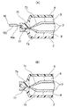
そして、このはみ出し状態において、上記の寸法設定により、はみ出し突起10の括れ部10aが頭部10bとともにケース2,4の外にはみ出してこれを視認することができるときには、これによりカシメ工程が正常に行なわれたことを確認することができる。また、図6(A)および(B)に示すように、括れ部10aがケース2,4の外にはみ出しておらず、よってこれを視認することができないときには、この分余計に不織布7の一片7cがケース2,4の内側に入り込んでいることになるために、ケース2,4の内部で、例えば図13(B)に示したようなカシメ不良が発生していることを知ることができる。したがって、このようにカシメ後にはみ出し突起10のはみ出し状態を確認することにより、不織布7の開放端部7bが上下のケース2,4間に正常にカシメ固定されたか否かをケース2,4の外部から判定することができる。
【0031】
また、はみ出し突起10が括れ部10aおよび頭部10bを備えた耳状突起として形成されるとともに、このはみ出し突起10の括れ部10aがカシメが正常に行なわれたときにケース2,4の外にはみ出してこれを外部から視認することができるようその長さ寸法Lを設定されているために、当該方法によれば、カシメ良否の判定作業を括れ部10aがケース2,4の外にはみ出しているか否かを見るだけという単純な目視作業によって行なうことができる。したがって、はみ出し突起10のはみ出し量をいちいち測定する必要がないために、判定作業を極めて単純で容易なものとすることができる。比較的幅狭の括れ部10aの外側に比較的幅広の頭部10bを一体成形した耳状のはみ出し突起10は、頭部10bが幅広であるために、突起10を掴み易く、利用後に切除し易い。
【0032】
また、図7(A)および(B)に示すように、上記はみ出し突起17を利用して、このはみ出し突起10を治具12,13で掴んで正常な位置に固定した状態でカシメを行なうようにすると、不織布7の一片7cがケース2,4の内側に余分に入り込んだり、一片7cが起き上がったりした状態でカシメが行なわれるのを未然に防止することができる。したがってこの場合には、カシメを正確に行なうことができ、不織布7の開放端部7bを上下のケース2,4間に確実にカシメ固定することができる。
【0033】
上記はみ出し突起10の形状はカシメ良否の判定を行なうことができるものであればどのような形状でも良いが、上記したように判定作業の容易性を確保するには、括れ部10aを備えた耳状のものであることが望ましい。この耳状のはみ出し突起10としては、上記図5に示したものの外、図8ないし図10に示す例を挙げることができる。
【0034】
すなわち、上記図5の例では頭部10bの平面形状が四角形とされているが、図8の例では頭部10bの平面形状が半円形とされている。また、上記図5の例では括れ部10aの幅が全長に亙って一定とされているが、図9の例では括れ部10aの幅が不織布7から頭部10bへかけて漸次拡がる形状とされている。また、図10の例では頭部10bの平面形状が半円形とされ、かつ括れ部10aの幅が不織布7から頭部10bへかけて漸次拡がる形状とされている。
【0035】
【発明の効果】
本発明は、以下の効果を奏する。
【0036】
すなわち先ず、上記構成を備えた本発明の請求項1によるオイルストレーナの製造方法においては、カシメ後にはみ出し突起のはみ出し量を測定して、はみ出し突起がケースの外に所定量はみ出している場合には、これによりカシメが正常に行なわれたことを確認することができ、また、はみ出し量が足りない場合にはこの分余計に不織布の開放端部がケースの内側に入り込んでいることになるために、カシメ不良が発生していることを知ることができる。したがって、このようにカシメ後にはみ出し突起のはみ出し状態を確認することによって不織布の開放端部が上下のケース間に正常にカシメ固定されたか否かをケースの外部から容易に判定することができる。
【0037】
また、上記構成を備えた本発明の請求項2によるオイルストレーナの製造方法においては、カシメ後にはみ出し突起の括れ部がケースの外にはみ出している場合には、これによりカシメが正常に行なわれたことを確認することができ、また括れ部がはみ出していない場合には、この分余計に不織布の開放端部がケースの内側に入り込んでいることになるために、カシメ不良が発生していることを知ることができる。したがって、このようにカシメ後にはみ出し突起のはみ出し状態を確認することによって不織布の開放端部が上下のケース間に正常にカシメ固定されたか否かをケースの外部から容易に判定することができる。
【0038】
また、はみ出し突起が括れ部を備えた耳状突起とされ、括れ部がカシメが正常に行なわれたときにケースの外にはみ出す長さ寸法を備えているために、判定作業を括れ部がケースの外にはみ出しているか否かを見るだけという単純な目視作業によって行なうことができる。したがって、はみ出し突起のはみ出し量をいちいち測定する必要がないために、判定作業を極めて単純で容易なものとすることができる。
【0039】
また、上記構成を備えた本発明の請求項3によるオイルストレーナの製造方法においては、はみ出し突起を治具等で掴んで正常な位置に固定した状態でカシメ工程を行なうために、不織布の開放端部がケースの内側に余分に入り込んだり、その一片が起き上がったりした状態でカシメ工程が行なわれるを未然に防止することができる。したがって、カシメ工程を正確に行なうことができ、不織布の開放端部を上下のケース間に確実にカシメ固定することができる。
【図面の簡単な説明】
【図1】本発明の実施例に係る製造方法によって製造されるオイルストレーナの平面図
【図2】図1におけるA−B−C−D線断面図
【図3】(A)は図2の要部拡大図、(B)は図1におけるE−E線拡大断面図
【図4】同オイルストレーナの製造過程を示す断面図
【図5】同オイルストレーナに用いる不織布の展開状態を示す要部平面図
【図6】(A)は不織布カシメ部に不具合が発生した状態を示す断面図、(B)は同平面図
【図7】(A)は同オイルストレーナの製造過程を示す断面図、(B)はカシメ完了状態を示す断面図
【図8】はみ出し突起の他の例を示す不織布の要部平面図
【図9】はみ出し突起の他の例を示す不織布の要部平面図
【図10】はみ出し突起の他の例を示す不織布の要部平面図
【図11】従来例に係るオイルストレーナの断面図
【図12】同オイルストレーナの製造過程を示す断面図
【図13】(A)は図11の要部拡大図、(B)は不織布カシメ部に不具合が発生した状態を示す断面図
【符号の説明】
1 オイルストレーナ
2 下ケース
3 オイル流入口
4 上ケース
5 オイル流出口
6 空間
7 不織布
7a 折り返し端部
7b 開放端部
7c 上側一片
7d 下側一片
8,9 リブ
10 はみ出し突起
10a 括れ部
10b 頭部
11 溶着部
12,13 挟み治具[0001]
BACKGROUND OF THE INVENTION
The present invention relates to a method for manufacturing an oil strainer used in an oil circulation system or the like in an automatic transmission (AT) of an automobile.
[0002]
[Prior art]
Conventionally, an oil strainer 1 shown in FIG. 11 is known and is configured as follows.
[0003]
That is, first, the
[0004]
As shown in FIG. 12, the oil strainer 1 folds the sheet-like
[0005]
That is, when the
[0006]
Further, even if such a caulking defect occurs, it cannot be confirmed from the outside of
[0007]
[Problems to be solved by the invention]
In view of the above, the present invention provides an oil strainer manufacturing method including means capable of confirming from the outside of a case whether or not the open end portion of the nonwoven fabric is normally caulked and fixed between the upper and lower cases. The purpose is to do.
[0008]
[Means for Solving the Problems]
In order to achieve the above object, a manufacturing method according to claim 1 of the present invention is a method for manufacturing an oil strainer in which a nonwoven fabric serving as a filter is folded back and its open ends are caulked and fixed between upper and lower cases. When the caulking is normally performed, a protruding protrusion that protrudes a predetermined amount outside the case is provided, and after the caulking, the open end is normally operated depending on whether or not the protruding protrusion protrudes outside the case. It is characterized by determining whether or not the caulking is fixed.
[0009]
The manufacturing method according to
[0010]
The manufacturing method according to claim 3 of the present invention is the method of manufacturing an oil strainer according to
[0011]
In the manufacturing method according to claim 1 of the present invention having the above-described configuration, the amount of protrusion of the protrusion is measured after crimping, and when the protrusion protrudes outside the case by a predetermined amount, the crimping is normal. If the amount of protrusion is not sufficient, the open end of the nonwoven fabric will enter the inside of the case, which will cause a caulking defect. You can know what you are doing.
[0012]
Further, in the manufacturing method according to
[0013]
Further, as in the manufacturing method according to claim 3 of the present invention having the above-described configuration, when the caulking process is performed in a state where the protruding protrusion is grasped with a jig or the like and fixed at a normal position, the open end portion of the nonwoven fabric becomes the case. It is possible to prevent the caulking process from being carried out in a state in which it has entered excessively inside or one piece has risen.
[0014]
The proposal includes the following technical matters.
[0015]
That is, in order to achieve the above object, one oil strainer proposed in the present application is a strainer using a nonwoven fabric with ears, and in a resin oil strainer using a nonwoven fabric as a filter, the oil strainer is parallel to the folding position of the nonwoven fabric. Using a non-woven fabric with an ear-shaped protrusion with a constriction on one side (the one that rises when caulking with the case), the ear-shaped protrusion protrudes from the strainer body when an oil strainer assembly is made. Is an oil strainer characterized by The otic protrusion may have any shape as long as it can confirm the lack of caulking, but is preferably provided with a constriction.
[0016]
The embodiment of the oil strainer is as follows.
[0017]
An ear projection is provided on one side of the nonwoven fabric used as a filter. A constriction is provided in the otic process. It is desirable to set the length of the constriction so that the constriction coming out of the strainer body is the same as the allowable amount of non-woven fabric displacement. The ear-shaped protrusion is provided on one side parallel to the folded back of the nonwoven fabric. The side where the ear-shaped protrusion is provided is set so as to be on the upper side when the case and the nonwoven fabric are crimped. The size of the ear protrusion and the constriction is set to such a size that the shape can be visually recognized (easy to pinch with a finger).
[0018]
According to the oil strainer, the following operational effects can be achieved.
[0019]
(1) Even if the non-woven fabric is displaced when the non-woven fabric is caulked, the lack of caulking can be easily identified by concealing the constriction of the ear-like projections that go out of the strainer (non-woven caulking defective product) Reduction of sorting time).
▲ 2 ▼ By pinching and fixing the ear projections with a jig or the like during non-woven caulking, it is possible to prevent the non-woven fabric from rising and prevent problems such as lack of caulking (disengagement of the caulking part). Defect prevention (quality improvement)).
(3) The otic process can be easily excised with a blade after caulking, and the appearance is the same as a general popular product, and no new contamination is generated in the AT.
[0020]
The inventions according to
[0021]
(1) A method for determining whether or not the non-woven fabric to be used as a filter is folded and the open ends thereof are caulked and fixed between the upper and lower cases, and the caulking is normally performed on the open ends of the non-woven fabric. A protruding protrusion protruding outside the case by a predetermined amount, and determining whether or not the open end is normally fixed by crimping according to whether the protruding protrusion protrudes outside the case by a predetermined amount after crimping. A caulking quality determination method characterized by the above.
(2) In the caulking quality determination method according to (1) above, the protruding protrusion is an ear-shaped protrusion having a constricted portion, and the constricted portion is a length that protrudes outside the case when the caulking is performed normally. A caulking quality determination method comprising: determining whether or not the open end portion is normally caulked and fixed based on whether or not the constricted portion protrudes outside the case after caulking .
[0022]
DETAILED DESCRIPTION OF THE INVENTION
Next, embodiments of the present invention will be described with reference to the drawings.
[0023]
FIG. 1 shows a plan view of an oil strainer manufactured by a manufacturing method according to an embodiment of the present invention, and a cross-sectional view taken along the line A-B-C-D is shown in FIG. 3A is an enlarged view of a main part of FIG. 2, and FIG. 3B is an enlarged cross-sectional view taken along line EE in FIG.
[0024]
The oil strainer 1 is configured as follows.
[0025]
That is, first, as shown in FIG. 2, a resin
[0026]
As shown in FIG. 4, the oil strainer 1 is formed by folding a sheet-like
[0027]
That is, the protruding
[0028]
As shown in FIG. 5, the protruding
[0029]
When the
[0030]
In this protruding state, when the above-mentioned dimension setting allows the
[0031]
Further, the protruding
[0032]
Further, as shown in FIGS. 7 (A) and 7 (B), by using the protruding protrusion 17, the protruding
[0033]
The protruding
[0034]
That is, in the example of FIG. 5, the planar shape of the
[0035]
【The invention's effect】
The present invention has the following effects.
[0036]
That is, first, in the method of manufacturing an oil strainer according to the first aspect of the present invention having the above-described configuration, the amount of protrusion of the protrusion is measured after caulking, and when the protrusion protrudes outside the case by a predetermined amount. Because of this, it can be confirmed that the caulking has been performed normally, and when the amount of protrusion is insufficient, the open end of the nonwoven fabric has entered the inside of the case. It is possible to know that a caulking defect has occurred. Therefore, it is possible to easily determine from the outside of the case whether or not the open end portion of the nonwoven fabric is normally crimped between the upper and lower cases by checking the protruding state of the protruding protrusions after crimping.
[0037]
Further, in the method of manufacturing an oil strainer according to
[0038]
Also, since the protruding protrusion is an ear-shaped protrusion with a constricted portion, and the constricted portion has a length dimension that protrudes outside the case when the caulking is performed normally, the constricting portion is used for the judgment work. It can be performed by a simple visual operation of just seeing whether or not it protrudes outside. Accordingly, since it is not necessary to measure the amount of protrusion of the protrusion, it is possible to make the determination work extremely simple and easy.
[0039]
In the method of manufacturing an oil strainer according to claim 3 of the present invention having the above-described configuration, the open end of the nonwoven fabric is used to perform the caulking process in a state where the protruding protrusion is grasped with a jig or the like and fixed in a normal position. It is possible to prevent the caulking process from being performed in a state in which the portion has excessively entered the inside of the case or a piece thereof has risen. Therefore, the crimping process can be performed accurately, and the open end of the nonwoven fabric can be securely crimped between the upper and lower cases.
[Brief description of the drawings]
FIG. 1 is a plan view of an oil strainer manufactured by a manufacturing method according to an embodiment of the present invention. FIG. 2 is a cross-sectional view taken along line A-B-C-D in FIG. Fig. 4 is an enlarged cross-sectional view taken along line E-E in Fig. 1. Fig. 4 is a cross-sectional view showing the manufacturing process of the oil strainer. Fig. 5 is an essential portion showing the unfolded state of the nonwoven fabric used in the oil strainer. [FIG. 6] (A) is a cross-sectional view showing a state in which a non-woven fabric caulking portion is defective, (B) is a plan view thereof. [FIG. 7] (A) is a cross-sectional view showing a manufacturing process of the oil strainer. FIG. 8B is a cross-sectional view showing the crimped state. FIG. 8 is a plan view of the main part of the nonwoven fabric showing another example of the protrusion. FIG. 9 is a plan view of the main part of the nonwoven fabric showing another example of the protrusion. ] Plan view of the main part of the nonwoven fabric showing another example of the protruding protrusion [FIG. 11] Oil according to the conventional example Cross-sectional view of the trainer [FIG. 12] Cross-sectional view showing the manufacturing process of the oil strainer [FIG. 13] (A) is an enlarged view of the main part of FIG. Figure [Explanation of symbols]
DESCRIPTION OF SYMBOLS 1
Claims (3)
前記不織布(7)の開放端部(7b)にカシメが正常に行なわれたときに前記ケース(2)(4)の外に所定量はみ出すはみ出し突起(10)を設け、カシメ後に前記はみ出し突起(10)が前記ケース(2)(4)の外に所定量はみ出しているか否かにより前記開放端部(7b)が正常にカシメ固定されたか否かを判定することを特徴とするオイルストレーナの製造方法。In the manufacturing method of the oil strainer (1) in which the nonwoven fabric (7) to be a filter is folded and the open end (7b) is caulked and fixed between the upper and lower cases (2) and (4),
When the caulking is normally performed on the open end (7b) of the non-woven fabric (7), a protruding protrusion (10) protruding a predetermined amount is provided outside the case (2) (4), and the protruding protrusion ( 10) determining whether or not the open end (7b) is normally crimped by whether or not a predetermined amount protrudes outside the cases (2) and (4). Method.
はみ出し突起(10)が括れ部(10a)を備えた耳状突起であり、前記括れ部(10a)はカシメが正常に行なわれたときに前記ケース(2)(4)の外にはみ出す長さ寸法(L)を備えており、カシメ後に前記括れ部(10a)が前記ケース(2)(4)の外にはみ出しているか否かにより前記開放端部(7b)が正常にカシメ固定されたか否かを判定することを特徴とするオイルストレーナの製造方法。In the manufacturing method of the oil strainer of Claim 1,
The protruding protrusion (10) is an ear-shaped protrusion having a constricted portion (10a), and the constricted portion (10a) is a length that protrudes outside the case (2) (4) when caulking is performed normally. Whether or not the open end (7b) is normally crimped by whether or not the constricted portion (10a) protrudes outside the case (2) (4) after crimping. An oil strainer manufacturing method characterized by determining whether or not.
はみ出し突起(10)を治具(11)(12)等で掴んで正常な位置に固定した状態でカシメ工程を行なうことを特徴とするオイルストレーナの製造方法。In the manufacturing method of the oil strainer of Claim 1 or 2,
A method of manufacturing an oil strainer, wherein the caulking process is performed in a state where the protruding protrusion (10) is held by a jig (11) (12) or the like and fixed at a normal position.
Priority Applications (1)
| Application Number | Priority Date | Filing Date | Title |
|---|---|---|---|
| JP2001339151A JP3734026B2 (en) | 2001-11-05 | 2001-11-05 | Oil strainer manufacturing method |
Applications Claiming Priority (1)
| Application Number | Priority Date | Filing Date | Title |
|---|---|---|---|
| JP2001339151A JP3734026B2 (en) | 2001-11-05 | 2001-11-05 | Oil strainer manufacturing method |
Publications (2)
| Publication Number | Publication Date |
|---|---|
| JP2003135912A JP2003135912A (en) | 2003-05-13 |
| JP3734026B2 true JP3734026B2 (en) | 2006-01-11 |
Family
ID=19153544
Family Applications (1)
| Application Number | Title | Priority Date | Filing Date |
|---|---|---|---|
| JP2001339151A Expired - Fee Related JP3734026B2 (en) | 2001-11-05 | 2001-11-05 | Oil strainer manufacturing method |
Country Status (1)
| Country | Link |
|---|---|
| JP (1) | JP3734026B2 (en) |
Families Citing this family (1)
| Publication number | Priority date | Publication date | Assignee | Title |
|---|---|---|---|---|
| JP4622665B2 (en) * | 2005-05-12 | 2011-02-02 | トヨタ紡織株式会社 | Oil filter for automatic transmission |
-
2001
- 2001-11-05 JP JP2001339151A patent/JP3734026B2/en not_active Expired - Fee Related
Also Published As
| Publication number | Publication date |
|---|---|
| JP2003135912A (en) | 2003-05-13 |
Similar Documents
| Publication | Publication Date | Title |
|---|---|---|
| EP0308098B1 (en) | Flexible filter bag and method of fabrication | |
| JP3936188B2 (en) | Filter device having clip joint formed and fused and machine for producing the same | |
| JP2000061214A (en) | Fluid filter | |
| JP3734026B2 (en) | Oil strainer manufacturing method | |
| DE10254637A1 (en) | Temperature sensor for use in e.g. catalyst converter of exhaust gas purification apparatus, exhaust tube of automobile, has flange having sheath in which metal tube is pushed in or clamped and welded at peripheral direction | |
| CN203017908U (en) | Filter assembly | |
| JP2003053122A (en) | Filtering system | |
| WO2005014141A1 (en) | Case with partition member | |
| US8216496B2 (en) | Filter element with sealing and method of producing the filter element | |
| JPH07269437A (en) | Filter for fuel tank | |
| JPH08168629A (en) | Foldable filter unit | |
| EP3010619B1 (en) | Filter providing coarse media with high-efficiency insert | |
| US20030006182A1 (en) | Fluid filter for vehicle solenoid valve | |
| JP4637407B2 (en) | strainer | |
| JP2002235840A (en) | Fluid filter for automatic transmission | |
| JP2590805Y2 (en) | strainer | |
| US20020174772A1 (en) | Filter cassette and injection-molding tool for manufacturing the filter cassette frame | |
| EP3269285A1 (en) | Cleaning sheet and cleaning instrument | |
| JP2007275590A (en) | Fluid-tight slide fastener | |
| JPH08240296A (en) | Piping strainer and mounting structure thereof | |
| JP2002355509A (en) | Mesh and method of manufacturing the same, and filter using mesh and method of manufacturing the same | |
| JPH0612287Y2 (en) | Fluid filter device for automatic transmission | |
| US10213722B2 (en) | Heat sealed recyclable filter | |
| CN221156131U (en) | A separation component | |
| JP4446594B2 (en) | Oil strainer and manufacturing method thereof |
Legal Events
| Date | Code | Title | Description |
|---|---|---|---|
| A621 | Written request for application examination |
Free format text: JAPANESE INTERMEDIATE CODE: A621 Effective date: 20040514 |
|
| A977 | Report on retrieval |
Free format text: JAPANESE INTERMEDIATE CODE: A971007 Effective date: 20050921 |
|
| TRDD | Decision of grant or rejection written | ||
| A01 | Written decision to grant a patent or to grant a registration (utility model) |
Free format text: JAPANESE INTERMEDIATE CODE: A01 Effective date: 20050928 |
|
| A61 | First payment of annual fees (during grant procedure) |
Free format text: JAPANESE INTERMEDIATE CODE: A61 Effective date: 20051011 |
|
| R150 | Certificate of patent or registration of utility model |
Free format text: JAPANESE INTERMEDIATE CODE: R150 |
|
| LAPS | Cancellation because of no payment of annual fees |