JP3733643B2 - Method for manufacturing passenger airbag - Google Patents
Method for manufacturing passenger airbag Download PDFInfo
- Publication number
- JP3733643B2 JP3733643B2 JP15201296A JP15201296A JP3733643B2 JP 3733643 B2 JP3733643 B2 JP 3733643B2 JP 15201296 A JP15201296 A JP 15201296A JP 15201296 A JP15201296 A JP 15201296A JP 3733643 B2 JP3733643 B2 JP 3733643B2
- Authority
- JP
- Japan
- Prior art keywords
- airbag
- surplus
- reinforcing
- main panel
- opening
- Prior art date
- Legal status (The legal status is an assumption and is not a legal conclusion. Google has not performed a legal analysis and makes no representation as to the accuracy of the status listed.)
- Expired - Fee Related
Links
Images


Description
【0001】
【発明の属する技術分野】
本発明は、車両の助手席前方のインストルメントパネルに配置される助手席用エアバッグ装置のエアバッグに関する。
【0002】
【従来の技術とその課題】
従来、この種の助手席用エアバッグにおいては、特開平5−262195号公報に記載されているように、エアバッグ内に、半割り円筒状の帯状の布材からなる整流布を配置させたものが知られている。
【0003】
このような助手席用エアバッグでは、膨張用ガスを流入させて膨張する際、整流布により、膨張用ガスを流入させる開口部と対向した天井部の移動速度を抑えることができる。
【0004】
しかし、上記公報記載のエアバッグでは、整流布を設けて製造する工数やコストが増大していた。
【0005】
すなわち、通常の助手席用エアバッグでは、天井部周縁から延びる4つの周壁部の先端に、膨張用ガスを流入させる開口部を有した袋形状としている。さらに、天井部及び天井部を間にして対向する2つの周壁部を構成するメインパネルと、メインパネルで構成する以外の周壁部をそれぞれ構成して、メインパネルの両縁に縫合される2枚のサイドパネルと、から形成されている。
【0006】
そのため、整流布を設けた助手席用エアバッグを製造する際には、まず、メインパネルの一端に、整流布の一端を縫合する。ついで、メインパネルに2枚のサイドパネルを縫合して、袋形状にする。その後、整流布の他端をメインパネルに縫合して、製造することとなっていた。
【0007】
しかしながら、この整流布の他端を縫合する作業は、既にメインパネルとサイドパネルとが縫合されて袋形状となって立体的になっていることから、行ない難かった。
【0008】
本発明は、上述の課題を解決するものであり、内部に整流布の作用を奏する部材を設けても、容易に製造できて、工数・コストを低減することができる助手席用エアバッグを提供することを目的とする。
【0009】
【課題を解決するための手段】
本発明に係る助手席用エアバッグは、天井部周縁から延びる4つの周壁部の先端に、膨張用ガスを流入させる開口部を有するとともに、該開口部周縁の前記各周壁部に補強布を縫合させた袋形状として、
前記天井部及び前記天井部を間にして対向する2つの周壁部とを構成するメインパネルと、該メインパネルで構成する以外の周壁部をそれぞれ構成して、前記メインパネルの両縁に縫合される2枚のサイドパネルと、からなり、
さらに、膨張用ガスの流入時に前記天井部の移動速度を抑え可能に前記開口部と対向するように配置される整流布の作用を奏する部材、を有した助手席用エアバッグの製造方法であって、
前記各周壁部に縫合される4枚の前記補強布の内、前記開口部周縁で対向する2枚の補強布が、前記整流布の作用を奏する部材を形成可能に、エアバッグの内側に延びて前記周壁部に縫合されない余剰部を備えた余剰部付補強布とされ、
前記メインパネルと2枚の前記サイドパネルとの前記開口部の周縁部位に、対応する補強布を縫合させた状態で、前記メインパネルと2枚の前記サイドパネルとを縫合して袋形状とする行程と、
袋形状に形成した後に、前記整流布の作用を奏する部材を形成するように、前記余剰部付補強布の前記余剰部の先端側相互を、外方に出して、両側を開放させた状態で縫合し、ついで、前記余剰部をエアバッグ内に収納する行程と、
を具備して製造するとともに、
前記前記余剰部付補強布の前記余剰部の先端側相互の縫合時における開放する両側を、左右方向両側若しくは上下方向両側として、製造することを特徴とする。
【0010】
【発明の効果】
本発明に係る製造方法では、それぞれ所定の補強布を縫合させたメインパネルとサイドパネルとを縫合して袋形状とした後に、既に縫合しておいた余剰部付補強布の余剰部の先端側相互を、外方に出して、両側を開放させた状態で縫合し、ついで、余剰部をエアバッグ内に収納する行程を経れば、余剰部付補強布の余剰部で整流布を形成することができる。
【0011】
そして、余剰部付補強布自体は、メインパネル若しくはサイドパネルにおける周壁部を構成する所定部位に縫合しておくだけであり、その作業は、他の2つの補強布と同様に、周壁部の開口部周縁を構成する平面状の所定部位に縫合する作業であり、簡単に縫合することができる。ちなみに、従来の助手席用エアバッグでも、開口部周縁の4つの周壁部には、膨張用ガスの流入時の熱と圧力との影響を抑えるように、補強布が縫合されており、本発明の余剰部付補強布の周壁部への縫合作業は、従来の助手席用エアバッグの製造に比べて、工数やコストを増加させるものではない。
【0012】
また、対向している余剰部付補強布の余剰部相互を縫合する作業は、エアバッグの外方に余剰部の先端側相互を出して、行なうことから、立体的な縫合作業でなく、平面的な縫合作業で行なうことができて、容易に行なえる。
【0013】
したがって、本発明に係る助手席用エアバッグの製造方法では、整流布を構成する部材を、開口部周縁の対向する周壁部に縫合される補強布に余剰部を設けたものとし、それらの余剰部を平面的に縫合するだけで、整流布の作用を奏する部材を容易に製造できて、製造工数・製造コストを低減することができる。
【0014】
【発明の実施の形態】
以下、本発明の一実施形態を図面に基づいて説明する。
【0015】
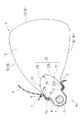
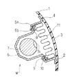
実施形態の助手席用エアバッグ11は、図1・2に示すように、助手席前方のインストルメントパネル(以下、インパネとする)1の下部に設けられる助手席用エアバッグ装置Mに使用されるものである。助手席用エアバッグ装置Mは、エアバッグ11と、エアバッグ11内に膨張用ガスを供給するインフレーター7と、折り畳まれたエアバッグ11及びインフレーター7を保持するケース6と、を備えて構成されている。
【0016】
ケース6は、上方を開口させ、段差面6aを有した板金製の箱形状として、車両の所定部位に連結固定するための図示しないブラケットを有して構成されている。段差面6aは、上方から見て四角環状に形成されて、エアバッグ11を接続する部位となり、後述するリテーナ8のボルト9を挿通させるための複数の貫通孔6bを備えている。
【0017】
インフレーター7は、ガス吐出口7aを有したシリンダタイプとして、両端をケース6の周壁に取付固定させている。
【0018】
インパネ1には、膨張時のエアバッグ11を突出させるための開口2が形成されるとともに、開口2には、ヒンジ部4で支持されたドア3が配設されている。このドア3は、エアバッグ11の膨張時にエアバッグ11に押され、ヒンジ部4を回転中心として開くこととなる。
【0019】
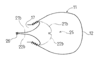
エアバッグ11は、図3の下段に示すように、膨張時の形状として、天井部12の周縁から4つの周壁部13・14・15・16を延ばした略四角筒形状の袋状として構成され、周壁部13・14・15・16の先端側に、膨張用ガスを流入させる開口部17を備えている。
【0020】
このエアバッグ11は、図3の上段・中段に示すように、天井部12及び天井部12を間にして対向する2つの周壁部13・14とを構成するメインパネル18と、メインパネル18で構成する以外の周壁部15・16をそれぞれ構成して、メインパネル18の両縁に縫合される2枚のサイドパネル19・20と、から構成されている。なお、各パネル18・19・20は、ポリアミドやポリエステル等の織布から形成されて、所望により、エアバッグ11の内周面側となる面に、耐熱性コーティング層が設けられている。
【0021】
また、開口部17の周縁における各周壁部13・14・15・16の内周面には、パネル18・19・20と同質の補強布21・22・23・24が縫合されている。メインパネル18に縫合される補強布21・22は、図3・4に示すように、周壁部13・14に縫合される本体21a・22aと、本体21a・22aからエアバッグ11内に延びて周壁部13・14に縫合されない長方形形状の余剰部21b・22bと、から構成されて、余剰部付補強布としている。
【0022】
そして、余剰部付補強布21・22は、両側を開放させた状態で、余剰部21b・22bの先端相互を縫合して、整流部25を構成している。
【0023】
このエアバッグ11の製造について述べると、まず、メインパネル18、サイドパネル19・20、余剰部付補強布21・22、及び、補強布23・24を裁断して形成しておく。なお、各パネル18・19・20における開口部17の周縁部位には、ケース6の段差面6aに取り付けるための接続孔11aを穿設しておく。
【0024】
そして、各パネル18・19・20に所定の補強布21・22・23・24を縫合糸26を利用して縫合する。余剰部付補強布21・22については、図3に示すように、本体21a・22bだけをパネル18に縫合しておく。
【0025】
ついで、メインパネル18と2枚のサイドパネル19・20との開口部17の周縁の部位に補強布21・22・23・24を縫合させた状態で、かつ、補強布21・22・23・24を外表面に配置させた状態で、メインパネル18と2枚のサイドパネル19・20とを縫合して袋形状とする。
【0026】
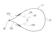
その後、袋形状に縫合した際の縫代がエアバッグ11の外周面側に表れないように、開口部17を利用して裏返し、さらに、図5の実線で示すように、余剰部付補強布21・22のエアバッグ11内に延びる余剰部21b・22bの先端側相互を、外方に取り出して両側を開放させた状態で、縫合糸26を利用して縫合し、ついで、図5の二点鎖線で示すように、余剰部21b・22bをエアバッグ11内に収納すれば、整流部25を有したエアバッグ11を製造することができる。
【0027】
そして、開口部17から四角環状で板金製のリテーナ8をエアバッグ11内に入れ、リテーナ8から延びる各ボルト9を接続孔11aから突出させて、エアバッグ11を折り畳む。
【0028】
その後、インフレーター7を取り付け済みのケース6における段差面6aの各貫通孔6bに、リテーナ8のボルト9を貫通させ、各ボルト9をナット10止めすれば、エアバッグ装置Mを組み立てることができる。
【0029】
そして、ケース6の図示しないブラケットを車両に固定すれば、助手席用エアバッグ装置Mを車両に装着することができる。
【0030】
その後、インフレーター7のガス吐出口7aから膨張用ガスが吐出されれば、開口部17から膨張用ガスがエアバッグ11に流入して、エアバッグ11は、図1に示すように、膨張し、ドア3を押し開いて、インパネ1の開口2から大きく突出することとなる。
【0031】
その際、エアバッグ11には、両側を開口させた状態として、開口部17に対向するように配置される整流部25が設けられているため、天井部12の移動速度を抑えることが可能となる。
【0032】
そして、実施形態のエアバッグ11の製造においては、それぞれ所定の補強布21・22・23・24を縫合させたメインパネル18とサイドパネル19・20とを縫合して袋形状とした後に、既に縫合しておいた余剰部付補強布21・22のエアバッグ11内に延びる余剰部21b・22bの先端側相互を、外方に取り出して、両側を開放させた状態で縫合し、ついで、余剰部21b・22bをエアバッグ11内に収納する行程を経れば、従来の整流布のような整流部25を形成することができる。
【0033】
そして、余剰部付補強布21・22自体は、メインパネル18における周壁部13・14を構成する所定部位に縫合しておくだけであり、その作業は、他の2つの補強布23・24と同様に、周壁部13・14の開口部17周縁を構成する平面状の所定部位に縫合する作業であり、簡単に縫合することができる。
【0034】
そしてまた、対向している余剰部付補強布21・22の余剰部21b・22b相互を縫合する作業は、エアバッグ11の外方に余剰部21b・22bの先端側相互を取り出して、行なうことから、立体的な縫合作業でなく、平面的な縫合作業で行なうことができて、容易に行なえる。
【0035】
したがって、実施形態のエアバッグ11の製造方法では、整流布を構成する整流部25を、開口部17周縁の対向する周壁部13・14に縫合される補強布21・22に余剰部21b・22bを設けたものとし、それらの余剰部21b・22bを平面的に縫合するだけで、整流布の作用を奏する整流部25を容易に製造できて、製造工数・製造コストを低減することができる。
【0036】
なお、整流部25を形成する場合には、補強布21・22・23・24を縫合済みのメインパネル18とサイドパネル19・20とを袋形状に縫合して、反転させる前に、図6に示すように、余剰部21b・22bを外方に出して、先端側相互を縫合し、その後、パネル18・19・20を反転させて、エアバッグ11内に余剰部21b・22bを収納させるようにしても良い。
【0037】
また、パネル18・19・20を反転させない場合(この場合には、パネル18・19・20を縫合して袋形状に形成する際、実施形態と相違して、補強布21・22・23・24を内周面側に配置させて、縫合することとなる)には、図7の実線で示すように、余剰部21b・22bを外方に引っ張り出して、先端側相互を縫合し、その後、二点鎖線で示すように、先端側相互をエアバッグ11内に収納させて、整流部25を形成しても良い。
【0038】
さらに、実施形態で製造したエアバッグ11では、メインパネル18に、整流部25を形成可能な余剰部付補強布21・22を縫合した場合を示したが、サイドパネル19・20に縫合する補強布23・24を余剰部付補強布として、サイドパネル19・20側から整流部25を形成するようにしても良い。この場合の整流部25では、左右方向両側を開放した実施形態と相違して、上下方向両側が開放されることとなる。ちなみに、実施形態の場合にも、メインパネル18の周壁部13・14相互を左右方向に配置させれば、整流部25が上下方向両側を開放させることとなり、このようにエアバッグ11を配設しても良い。
【0039】
さらにまた、実施形態では、整流部25を形成する余剰部21b・22bに、貫通孔を設けない場合を示したが、整流部25を形成する余剰部21b・22b、あるいは、上述の補強布23・24を余剰部付補強布とした場合の余剰部に、所定数で所望の開口面積の貫通孔を設け、整流部25の部位自体からも、貫通孔を介して、膨張用ガスを流すように構成しても良い。
【図面の簡単な説明】
【図1】本発明の一実施形態で製造したエアバッグの膨張時を示す使用態様断面図である。
【図2】同実施形態の膨張前の状態を示す使用態様断面図である。
【図3】同実施形態の製造行程を説明する図である。
【図4】同実施形態のメイパネルと余剰部付補強布とを示す平面図である。
【図5】同実施形態における余剰部付補強布の余剰部相互を縫合する状態を示す図である。
【図6】他の実施形態における余剰部付補強布の余剰部相互を縫合する状態を示す図である。
【図7】さらに他の実施形態における余剰部付補強布の余剰部相互を縫合する状態を示す図である。
【符号の説明】
11…エアバッグ、
12…天井部、
13・14・15・16…周壁部、
17…開口部、
18…メインパネル、
19・20…サイドパネル、
21・22…余剰部付補強布、
21b・22b…余剰部、
23・24…補強布、
25…整流部、
M…助手席用エアバッグ装置。[0001]
BACKGROUND OF THE INVENTION
The present invention relates to an airbag for an airbag device for a passenger seat disposed on an instrument panel in front of a passenger seat of a vehicle.
[0002]
[Prior art and its problems]
Conventionally, in this type of passenger seat airbag, as described in Japanese Patent Laid-Open No. 5-262195, a rectifying cloth made of a half-cylindrical belt-shaped cloth material is arranged in the airbag. Things are known.
[0003]
In such a passenger seat airbag, when the inflation gas is introduced and inflated, the moving speed of the ceiling portion facing the opening through which the inflation gas flows can be suppressed by the rectifying cloth.
[0004]
However, in the airbag described in the above publication, the number of man-hours and costs for manufacturing the rectifying cloth increased.
[0005]
In other words, a normal passenger seat airbag has a bag shape having openings through which inflation gas flows at the tips of four peripheral walls extending from the periphery of the ceiling. In addition, the main panel constituting the two peripheral wall portions facing each other with the ceiling portion and the ceiling portion interposed therebetween, and the peripheral wall portions other than the main panel are constituted respectively, and two pieces sewn to both edges of the main panel And side panels.
[0006]
Therefore, when manufacturing a passenger seat airbag provided with a rectifying cloth, first, one end of the rectifying cloth is stitched to one end of the main panel. Next, the two side panels are stitched to the main panel to form a bag shape. Thereafter, the other end of the rectifying cloth was sewn to the main panel to manufacture.
[0007]
However, it is difficult to sew the other end of the rectifying cloth because the main panel and the side panel are already stitched into a bag shape and become three-dimensional.
[0008]
The present invention solves the above-described problems, and provides a passenger seat airbag that can be easily manufactured and can reduce man-hours and costs even if a member that functions as a rectifying cloth is provided therein. The purpose is to do.
[0009]
[Means for Solving the Problems]
The airbag for a passenger seat according to the present invention has openings at the tips of four peripheral walls extending from the periphery of the ceiling, and sutures reinforcing cloths to the peripheral walls of the periphery of the opening. As the bag shape
A main panel that constitutes the ceiling part and the two peripheral wall parts facing each other with the ceiling part in between, and a peripheral wall part other than that constituted by the main panel are respectively constructed and stitched to both edges of the main panel. and two side panels that, Ri Tona,
Further, there is provided a method for manufacturing a passenger airbag having a member having an effect of a rectifying cloth disposed so as to face the opening so as to suppress a moving speed of the ceiling when inflating gas flows. And
Of the four reinforcing cloths sewn on the peripheral wall portions, two reinforcing cloths facing each other at the periphery of the opening extend to the inside of the airbag so as to form a member that functions as the rectifying cloth. And a surplus portion with a surplus portion that is not sewn to the peripheral wall portion,
The main panel and the two side panels are sewn into a bag shape in a state in which the corresponding reinforcing cloth is sewn to the peripheral portion of the opening of the main panel and the two side panels. The process,
After forming the bag shape, in a state where both ends of the surplus portions of the surplus portion of the reinforcing fabric with surplus portions are exposed outwardly and both sides are opened so as to form a member that functions as the rectifying fabric. Sewing, and then storing the surplus portion in an airbag;
And manufacturing with
It is characterized in that both sides opened at the time of stitching of the surplus portions of the surplus portions of the reinforcing fabric with surplus portions are manufactured as left and right direction sides or up and down direction sides .
[0010]
【The invention's effect】
In the manufacturing method according to the present invention, after the main panel and the side panel each stitched with a predetermined reinforcing cloth are stitched to form a bag shape, the leading end side of the surplus part of the reinforcing cloth with the surplus part already stitched If they go out to the outside and are stitched in a state where both sides are opened, then, after passing the process of storing the surplus part in the airbag, the surplus part of the surplus part of the reinforcing cloth with surplus part forms a rectifying cloth be able to.
[0011]
The surplus portion of the reinforcing cloth itself is simply sewn to a predetermined portion constituting the peripheral wall portion of the main panel or the side panel, and the operation is similar to the other two reinforcing cloths. This is an operation of sewing to a predetermined planar portion constituting the periphery of the portion, and can be easily sutured. Incidentally, even in a conventional passenger airbag, a reinforcing cloth is sewn on the four peripheral wall portions at the periphery of the opening so as to suppress the influence of heat and pressure when the inflating gas flows in. The sewing operation to the peripheral wall portion of the reinforcing fabric with surplus portion does not increase the number of man-hours and costs compared to the production of the conventional passenger seat airbag.
[0012]
In addition, the operation of stitching the surplus portions of the reinforcing fabric with surplus portions facing each other is performed by taking the leading end sides of the surplus portions outward from the airbag, so that it is not a three-dimensional stitching operation but a plane. It can be performed by a typical sewing operation and can be easily performed.
[0013]
Therefore, in the method for manufacturing a passenger airbag according to the present invention, the members constituting the rectifying cloth are provided with a surplus portion in the reinforcing cloth sewn to the opposed peripheral wall portions of the periphery of the opening. By simply stitching the portions flat, a member having the function of the rectifying cloth can be easily manufactured, and the number of manufacturing steps and manufacturing costs can be reduced.
[0014]
DETAILED DESCRIPTION OF THE INVENTION
Hereinafter, an embodiment of the present invention will be described with reference to the drawings.
[0015]
The
[0016]
The
[0017]
The
[0018]
The instrument panel 1 has an
[0019]
As shown in the lower part of FIG. 3, the
[0020]
As shown in the upper and middle stages of FIG. 3, the
[0021]
Further, reinforcing
[0022]
And the
[0023]
The production of the
[0024]
Then, predetermined reinforcing
[0025]
Next, the reinforcing
[0026]
Thereafter, the opening
[0027]
Then, a rectangular annular
[0028]
Thereafter, the airbag device M can be assembled by passing the
[0029]
If the bracket (not shown) of the
[0030]
Thereafter, if the inflation gas is discharged from the gas discharge port 7a of the
[0031]
At that time, since the
[0032]
In the manufacture of the
[0033]
The
[0034]
In addition, the operation of stitching the
[0035]
Therefore, in the manufacturing method of the
[0036]
When the rectifying
[0037]
Further, when the
[0038]
Furthermore, in the
[0039]
Furthermore, although the embodiment has shown the case where the
[Brief description of the drawings]
FIG. 1 is a cross-sectional view of a usage pattern showing an airbag manufactured according to an embodiment of the present invention when inflated.
FIG. 2 is a cross-sectional view of a usage pattern showing a state before expansion according to the embodiment;
FIG. 3 is a diagram for explaining a manufacturing process according to the embodiment.
FIG. 4 is a plan view showing a May panel and a reinforcing cloth with a surplus portion according to the embodiment.
FIG. 5 is a view showing a state in which the surplus portions of the surplus portion of the reinforcing fabric in the embodiment are stitched together.
FIG. 6 is a view showing a state in which the surplus portions of the surplus portion of the reinforcing fabric according to another embodiment are stitched together.
FIG. 7 is a view showing a state in which the surplus portions of the reinforcing cloth with surplus portions are stitched together in still another embodiment.
[Explanation of symbols]
11 ... Airbag,
12 ... the ceiling,
13.14.15.16 ... peripheral wall,
17 ... opening,
18 ... Main panel,
19.20 ... side panel,
21.22 ... Reinforcement cloth with surplus part,
21b, 22b ... surplus part,
23.24 ... Reinforcing cloth,
25 ... Rectifying part,
M ... Airbag device for passenger seat.
Claims (1)
前記天井部及び前記天井部を間にして対向する2つの周壁部とを構成するメインパネルと、該メインパネルで構成する以外の周壁部をそれぞれ構成して、前記メインパネルの両縁に縫合される2枚のサイドパネルと、からなり、
さらに、膨張用ガスの流入時に前記天井部の移動速度を抑え可能に前記開口部と対向するように配置される整流布の作用を奏する部材、を有した助手席用エアバッグの製造方法であって、
前記各周壁部に縫合される4枚の前記補強布の内、前記開口部周縁で対向する2枚の補強布が、前記整流布の作用を奏する部材を形成可能に、エアバッグの内側に延びて前記周壁部に縫合されない余剰部を備えた余剰部付補強布とされ、
前記メインパネルと2枚の前記サイドパネルとの前記開口部の周縁部位に、対応する補強布を縫合させた状態で、前記メインパネルと2枚の前記サイドパネルとを縫合して袋形状とする行程と、
袋形状に形成した後に、前記整流布の作用を奏する部材を形成するように、前記余剰部付補強布の前記余剰部の先端側相互を、外方に出して、両側を開放させた状態で縫合し、ついで、前記余剰部をエアバッグ内に収納する行程と、
を具備して製造するとともに、
前記前記余剰部付補強布の前記余剰部の先端側相互の縫合時における開放する両側を、左右方向両側若しくは上下方向両側として、製造することを特徴とする助手席用エアバッグの製造方法。As a bag shape having an opening through which inflation gas flows at the tip of the four peripheral walls extending from the periphery of the ceiling, and a reinforcing cloth stitched to the peripheral walls of the periphery of the opening,
A main panel that constitutes the ceiling part and two peripheral wall parts that face each other with the ceiling part in between, and a peripheral wall part other than that constituted by the main panel are respectively constructed and stitched to both edges of the main panel. and two side panels that, Ri Tona,
Further, there is provided a method for manufacturing a passenger airbag having a member having an effect of a rectifying cloth disposed so as to face the opening so as to suppress a moving speed of the ceiling when inflating gas flows. And
Of the four reinforcing cloths sewn on the peripheral wall portions, two reinforcing cloths facing each other at the periphery of the opening extend to the inside of the airbag so as to form a member that functions as the rectifying cloth. And a surplus portion with a surplus portion that is not sewn to the peripheral wall portion,
The main panel and the two side panels are sewn into a bag shape in a state in which the corresponding reinforcing cloth is sewn to the peripheral portion of the opening of the main panel and the two side panels. The process,
After forming the bag shape, in a state where both ends of the surplus portions of the surplus portion of the reinforcing fabric with surplus portions are exposed outwardly and both sides are opened so as to form a member that functions as the rectifying fabric. Sewing, and then storing the surplus portion in an airbag;
And manufacturing with
A method for manufacturing an airbag for a passenger seat, characterized in that both sides opened at the time of suturing between the front end sides of the surplus portion of the reinforcing fabric with surplus portion are manufactured as left and right direction sides or up and down direction sides .
Priority Applications (1)
| Application Number | Priority Date | Filing Date | Title |
|---|---|---|---|
| JP15201296A JP3733643B2 (en) | 1996-06-13 | 1996-06-13 | Method for manufacturing passenger airbag |
Applications Claiming Priority (1)
| Application Number | Priority Date | Filing Date | Title |
|---|---|---|---|
| JP15201296A JP3733643B2 (en) | 1996-06-13 | 1996-06-13 | Method for manufacturing passenger airbag |
Publications (2)
| Publication Number | Publication Date |
|---|---|
| JPH101006A JPH101006A (en) | 1998-01-06 |
| JP3733643B2 true JP3733643B2 (en) | 2006-01-11 |
Family
ID=15531139
Family Applications (1)
| Application Number | Title | Priority Date | Filing Date |
|---|---|---|---|
| JP15201296A Expired - Fee Related JP3733643B2 (en) | 1996-06-13 | 1996-06-13 | Method for manufacturing passenger airbag |
Country Status (1)
| Country | Link |
|---|---|
| JP (1) | JP3733643B2 (en) |
Families Citing this family (4)
| Publication number | Priority date | Publication date | Assignee | Title |
|---|---|---|---|---|
| JP3405182B2 (en) | 1998-03-27 | 2003-05-12 | 豊田合成株式会社 | Airbag device for passenger seat |
| DE29807424U1 (en) * | 1998-04-23 | 1998-08-27 | Trw Repa Gmbh | Knee protection device for vehicle occupants |
| JP4608072B2 (en) | 2000-02-25 | 2011-01-05 | タカタ株式会社 | Airbag device |
| JP4380315B2 (en) | 2003-04-03 | 2009-12-09 | タカタ株式会社 | Air bag, air bag device and vehicle |
-
1996
- 1996-06-13 JP JP15201296A patent/JP3733643B2/en not_active Expired - Fee Related
Also Published As
| Publication number | Publication date |
|---|---|
| JPH101006A (en) | 1998-01-06 |
Similar Documents
| Publication | Publication Date | Title |
|---|---|---|
| JP3365204B2 (en) | Airbag for airbag equipment | |
| US7073818B2 (en) | Air bag | |
| JP3357937B2 (en) | How to fold the side airbag | |
| JP5488539B2 (en) | Airbag device for passenger seat | |
| JP4743014B2 (en) | Passenger airbag | |
| US20150001836A1 (en) | Airbag apparatus for a front passenger seat | |
| US6382664B1 (en) | Passenger seat air bag | |
| US5683109A (en) | Two piece air bag with built in tether | |
| JP2020050182A (en) | Airbag | |
| JP2001171468A (en) | Side air bag device | |
| JP3733643B2 (en) | Method for manufacturing passenger airbag | |
| JP3174898B2 (en) | Vehicle airbag | |
| JP2020040460A (en) | Air bag for front passenger seat | |
| JP5029233B2 (en) | Head protection airbag | |
| JPH07232607A (en) | Air bag for vehicle and its manufacture | |
| JP3724382B2 (en) | Vehicle airbag | |
| JP3800702B2 (en) | Airbag | |
| JPH08119052A (en) | Air bag for air bag device | |
| JPH0811657A (en) | Air bag for air bag device | |
| JP3928238B2 (en) | Vehicle airbag | |
| JP4232313B2 (en) | Airbag manufacturing method | |
| JPH10315892A (en) | Air bag for assistant's seat of car | |
| JPH0769150A (en) | Air bag for vehicle | |
| JPH07125585A (en) | Air bag and unit thereof | |
| JP2001260790A (en) | Air bag for front passenger seat |
Legal Events
| Date | Code | Title | Description |
|---|---|---|---|
| A977 | Report on retrieval |
Free format text: JAPANESE INTERMEDIATE CODE: A971007 Effective date: 20041101 |
|
| A131 | Notification of reasons for refusal |
Free format text: JAPANESE INTERMEDIATE CODE: A131 Effective date: 20041116 |
|
| A521 | Written amendment |
Free format text: JAPANESE INTERMEDIATE CODE: A523 Effective date: 20050113 |
|
| TRDD | Decision of grant or rejection written | ||
| A01 | Written decision to grant a patent or to grant a registration (utility model) |
Free format text: JAPANESE INTERMEDIATE CODE: A01 Effective date: 20050927 |
|
| A61 | First payment of annual fees (during grant procedure) |
Free format text: JAPANESE INTERMEDIATE CODE: A61 Effective date: 20051010 |
|
| R150 | Certificate of patent or registration of utility model |
Free format text: JAPANESE INTERMEDIATE CODE: R150 |
|
| FPAY | Renewal fee payment (event date is renewal date of database) |
Free format text: PAYMENT UNTIL: 20081028 Year of fee payment: 3 |
|
| FPAY | Renewal fee payment (event date is renewal date of database) |
Free format text: PAYMENT UNTIL: 20091028 Year of fee payment: 4 |
|
| FPAY | Renewal fee payment (event date is renewal date of database) |
Free format text: PAYMENT UNTIL: 20091028 Year of fee payment: 4 |
|
| FPAY | Renewal fee payment (event date is renewal date of database) |
Free format text: PAYMENT UNTIL: 20101028 Year of fee payment: 5 |
|
| LAPS | Cancellation because of no payment of annual fees |