JP3733245B2 - Large printer - Google Patents
Large printer Download PDFInfo
- Publication number
- JP3733245B2 JP3733245B2 JP24603998A JP24603998A JP3733245B2 JP 3733245 B2 JP3733245 B2 JP 3733245B2 JP 24603998 A JP24603998 A JP 24603998A JP 24603998 A JP24603998 A JP 24603998A JP 3733245 B2 JP3733245 B2 JP 3733245B2
- Authority
- JP
- Japan
- Prior art keywords
- printer
- spindle
- paper
- roll paper
- feeding unit
- Prior art date
- Legal status (The legal status is an assumption and is not a legal conclusion. Google has not performed a legal analysis and makes no representation as to the accuracy of the status listed.)
- Expired - Fee Related
Links
Images


Description
【0001】
【発明の属する技術分野】
本発明は、ロール紙を使用する大型プリンタに係り、特に幅420mm以上の大型の用紙に印刷するための大型プリンタに関する。
【0002】
【従来の技術】
従来技術におけるロール紙を使用する大型プリンタは、後方から前方に用紙搬送経路が構成され、ロール紙はプリンタ本体の後方に配置されているものが殆どである。このため、ロール紙を交換する時にわざわざプリンタ後方に作業者が回り込んで交換作業をしなければならない煩わしさがあると同時に前後方向での設置スペースが大型化する問題がある。
【0003】
また、ロール紙をプリンタ本体の前側に配置した構造のものも少しあるが、U字搬送経路を形成して用紙を前方に排出することになるため、搬送経路の構造が複雑化すると共に複数のロール紙を配置しようとすると一層構造が複雑化する問題がある。
【0004】
尚、ロール紙を用いる大型プリンタではないが、プリンタ本体の前後方向での設置スペースを小型化するために、単票紙からなる用紙を記録部に供給する方向と該記録部から記録済みの用紙を排出する方向を含む副走査方向を略直線状とし、且つ暗箱を形成する筺体の対角方向に斜めに配置したものが提供されている(特開平2−59372号公報)。
【0005】
【発明が解決しようとする課題】
しかしながら、大型プリンタでは、ロール紙も大型となり、かなりの重さになるが、このようなロール紙を用いるプリンタであって、作業者が立ったまま腰を屈めたりせずに重いロール紙を交換でき且つプリンタ正面からロール紙交換作業をできるようにすることを考慮したり示唆した従来技術は無い。また、このようなロール紙を用いるプリンタであって、更に大型の剛性厚紙をも印刷できるようにすることを考慮した従来技術は無い。
【0006】
本発明の課題は、重くて大きなロール紙を用いるプリンタであって、作業者が立ったまま腰を屈めたりせずに、しかもプリンタ正面側から重いロール紙を交換でき、更に大型の剛性厚紙をも同様に立ったままプリンタ正面から印刷できるようにした大型プリンタを提供することにある。
【0007】
【課題を解決するための手段】
上記課題を達成するため、本願請求項1に記載の発明は、給紙部、印刷部及び排紙スタック部が上、中及び下の位置関係に配置され、前記給紙部から前記印刷部を経て前記排紙スタック部に向かう用紙搬送経路が、後述するロール紙の交換操作時の操作する側をプリンタ正面としたとき該プリンタの斜め上方の奥側から斜め下方の手前側にほぼ真っ直ぐに形成されて成る大型プリンタであって、前記給紙部はロール紙と剛性厚紙の両方を給紙できるものであると共に、当該給紙部は、作業者が該プリンタ正面に腰を曲げずに立った状態で前記ロール紙の交換及び剛性厚紙のセットを行える高さに配置され、且つプリンタの正面側から前記ロール紙の交換及び剛性厚紙のセットを行えるように形成され、前記用紙搬送経路は、前記給紙部にセットされたロール紙と剛性厚紙のいずれもが、該用紙搬送経路を該プリンタの斜め上方の奥側から斜め下方の手前側に向かってほぼ真っ直ぐに搬送されつつ印刷され排紙されるように構成されていることを特徴とするものである。
【0008】
本発明によれば、ロール紙が配置される給紙部の高さが作業者が立ったままロール紙を交換できる位置であり、しかもそれをプリンタ正面から行える構造なので、重いロール紙を交換するに際し、作業者が腰を屈めたり、プリンタの後方に回り込む必要が無く、容易且つ簡単に行うことができる。更に、大型の剛性厚紙をも同様に作業者が腰を屈めたりせずプリンタ正面から給紙部に簡単にセットすることができる。
【0009】
また、本願請求項2に記載の発明は、請求項1に記載された発明において、前記給紙部は複数のロール紙を斜め上下の相対配置で装着可能に構成されていることを特徴とするものである。本発明によれば、一つのロール紙を使い切ってもすぐに他のロール紙に切り換えることが可能であると共に、上側のロール紙の方から使い始めれば、下側のロール紙に切り換えた状態で印刷を継続しつつ上側のロール紙を新しく交換することが可能となる。
【0010】
また、本願請求項3に記載の発明は、請求項1又は2に記載された発明において、前記給紙部は、装着された前記ロール紙の前面に設けられるロール紙カバーが、前記剛性厚紙のセット状態での支え部を兼ねるように形成されていることを特徴とするものである。剛性厚紙でも大型であるものは、その端の一部だけで全体を支えると自由端側が自重で垂れ下がり、全体として湾曲するが、本発明によれば、印刷部より上流側に位置することになる前記ロール紙カバーに当該大型剛性厚紙の自重による変形を防止する支え部を兼用させているので、セット状態にある剛性厚紙を平らに保持することができ、もって印刷物の画質の低下を防止することができる。
【0011】
また、本願請求項4に記載の発明は、請求項1〜3のいずれかに記載された発明において、前記給紙部は、ロール紙が取り付けられる長尺なスピンドルの両端が載置される少なくとも一対のスピンドル受けを備え、一対のスピンドル受けの少なくとも一方は水平面内を回動可能に形成され、該回動可能なスピンドル受けにスピンドルの一端を載置し、該一方のスピンドル受けを支点に回動させて他方のスピンドル受けにスピンドルの他端を載置する構成としたことを特徴とするものである。
【0012】
本発明によれば、回動可能なスピンドル受けの向きを載置し易い向きに回動させ、しかもスピンドルの一端だけを最初に載置することができるため、従来のように作業者が両腕を前方に伸ばす必要が無く簡単である。また、スピンドルの一端を載置した後は、その全重量の半分はスピンドル受けで支えられるため、重量的な負荷が減少し、しかも回動可能なスピンドル受けを支点に回動させて他方のスピンドル受けにスピンドルの他端を載置するだけであるため、交換作業が極めて簡単である。
【0013】
また本願請求項5に記載の発明は、請求項1〜4のいずれかに記載された発明において、前記回動可能なスピンドル受けはプリンタ正面側へ回動させる付勢手段を備え、スピンドルが外された時は前記付勢手段の付勢力により前方斜め内側方向となる回動限界に自動的に位置することを特徴とする。
また本願請求項6に記載の発明は、請求項1〜5のいずれかに記載された発明において、前記用紙搬送経路は前記斜め方向に代えて、垂直であることを特徴とするものである。本発明によっても、重いロール紙を交換するに際し、作業者が腰を屈めたり、プリンタの後方に回り込む必要が無く、立ったままで正面から行うことができる。更に、大型の剛性厚紙をも同様に作業者が腰を屈めたりせずプリンタ正面から給紙部に簡単にセットすることができる。
【0014】
【発明の実施の形態】
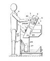
以下、本願発明の実施の形態を図面に基づいて説明する。図1は本発明に係る大型プリンタで作業者がロール紙交換作業している状態の概略縦断面図であり、図2は当該大型プリンタの概略正面図である。また、図3は同大型プリンタにより剛性厚紙を印刷する時の概略側面図であり、図4は同大型プリンタでロール紙を交換している状態の要部平面図であり、図5は当該大型プリンタの一対のスピンドル受け部分を示す要部拡大平面図であり、図6は同スピンドル受けにスピンドルの両端が載置された状態の平面図である。
【0015】
本実施の形態に係る大型プリンタは、図1に示した如く、給紙部30、印刷部7及び排紙スタック部8が上、中及び下の位置関係に配置されている。そして、前記給紙部30から前記印刷部7を経て前記排紙スタック部8に向かう用紙搬送経路が斜め上方の奥側から斜め下方の手前側にほぼ真っ直ぐに形成されている。当該給紙部30は、ロール紙3と大型の剛性厚紙21(図3参照)の両方を給紙できるものである。具体的には、ロール紙は給紙部30に交換時に取り外しできるように取り付けられており、また剛性厚紙21は、図3に示した如く、給紙部30の前面側の斜面に載置することによりセットできるように構成されている。
【0016】
尚、印刷部7は印字ヘッド22等の下方に前記用紙搬送経路の一部を成す平坦な排紙ガイド23を有し、該排紙ガイド23に吸引ファン24に連通された吸引口25が設けられている。該吸引口25はその吸引力に用紙を吸着し、その搬送状態を制御するものである。また、排紙スタック部8は印刷された用紙を受ける部分であり、排紙切換レバー26によって、ロール紙3の印刷時にはスタック布27をプリンタ前面に展開したり、図1に示した状態にして印刷物をプリンタ本体下部に誘導し、剛性厚紙21の印刷時には図3に示したように剛性厚紙21の排出の妨げに成らない位置に退避させるように形成されている。
【0017】
更に、当該給紙部30は、図1に示した如く、作業者9が立った状態でロール紙3の交換及び剛性厚紙21のセットを含む給紙のための処理を行える高さに配置されている。この高さは、この例では身長が170cm前後の作業者を対象にして作られている。尚、上下に高さ調整可能に構成すれば使用時に個々の作業者に最適な高さに設定することができる。更に、大型プリンタの正面側(図1の作業者のいる側)からロール紙3の交換などの給紙のための処理を行えるように形成されている。
【0018】
図2は上記実施の形態に係る大型プリンタの概略正面図であり、該大型プリンタの給紙部30は、一対のスピンドル受け1a、1bの下に更にもう一対のスピンドル受け2a、2bが設けられている。ロール紙3、3をそれぞれ取り付けた長尺な2本のスピンドル4、5が前記スピンドル受け1a、1b間及び2a、2b間に横架されている。すなわち、スピンドル4の両端4a、4bが一対のスピンドル受け1a、1bに載置され、スピンドル受け5の両端5a、5bがもう一対のスピンドル受け2a、2bに載置されている。図2において、符号6は前記スピンドル受け1a、1b及び2a、2b等が取り付けられるプリンタ本体のフレームを示す。
【0019】
図1に示した如く、前記2本のスピンドル4、5は、相対的に上側のスピンドル4が作業者9に対して後方となる斜め上下の関係に配置されている。そして、ロール紙3は、印刷部7及び排紙スタック部8の入り口に向かって斜め上下にほぼ一直線に形成された用紙搬送経路を搬送されるように配置されている。
【0020】
図3に示した如く、剛性厚紙21は、給紙部30の前面側の斜面に載置することによりセットできるように構成されているが、本実施の形態では、前記給紙部30は、装着されたロール紙3の前面に設けられるロール紙カバー28が、前記剛性厚紙21のセット状態での支え部29を兼ねるように形成されている。
【0021】
次に、図5に基づいて本実施の形態に係る大型プリンタの主構成要素であるスピンドル受け1a、1bの構造を説明する。尚、他のスピンドル受け2a、2bについては前記スピンドル受け1a、1bと同じ構造なので説明は省略する。一方のスピンドル受け1aは水平面内を回動可能に形成されている。この実施の形態ではフレーム6に固定された基台部10に回動部11が回動支点12を介して回動可能に構成されている。回動部11はスピンドル4の一端4aが載置される凹部13を有し、該凹部13の底部に一対のコロ14、14が回動支点12を挟んで対称に配置され、スピンドル4の回転負荷を低減するようになっている。
【0022】
更に、本実施の形態では、前記回動部11は、プリンタ正面側への回動限界が20度〜50度の角度に規制されている。好ましくは30度〜40度の範囲に規定され、この例ではプリンタ正面側への回動が約35度で停止するように形成されている。また、本実施の形態では、前記回動部11はプリンタ正面側へ回動するようにバネ(図示せず)を有し、スピンドル4が該スピンドル受け1aから外された時(図5の状態)は、前記バネの付勢力により回動限界である前記約35度の角度に自動的に位置するようになっている。
【0023】
更に、本実施の形態では、前記凹部13の奥側に係止部15が設けられている。一方、図6に示した如く、前記スピンドル4も、その一端4aに抜け止め16が設けられている。該抜け止め16は円形フランジ状に形成され、このフランジ状の抜け止め16が係止できるように前記係止部15の形状が形成されている。なお、この抜け止め15及び係止部16が、上記の形状に限定されないことは勿論である。
【0024】
次に、スピンドル4の他端4bが載置される他方のスピンドル受け1bの構造を図5に基づいて説明する。該スピンドル受け1bは、フレーム6に固定され、スピンドル4の他端4bが載置される凹部17を有し、該凹部17の底部に一対のコロ18、18が設けられている。該凹部17の形状は、スピンドル4の他端4bの円柱形状に対応して該円柱がフィットする単純形状に形成されている。
【0025】
また、本実施の形態では、前記スピンドル4の抜け止め16は、形状的に他端側の単純円柱形状と異なり、その形状の相違が一目瞭然となるように形成されている。従ってスピンドル4を左右間違えてセットする恐れを未然に防止する識別機能を当該フランジ形状によって有している。尚、図6において、符号20はロール紙3のフランジを示す。
【0026】
次に、上記実施の形態に係る大型プリンタで新しいロール紙に交換する際の交換作業を説明する。先ず、作業者9が、立った状態で且つプリンタ正面側から、スピンドル4を一対のスピンドル受け1a、1bから外すと、一方のスピンドル受け1aは、図示しないバネにより、図5に示した位置に自動的に向いて停止する。そして、図4に示したように、作業者9が、同じく立った状態で且つプリンタ正面側から、新しいロール紙3を取り付けた長尺なスピンドル4を持って先ず右側の一端4aを一方のスピンドル受け1aに載置する。尚、作業者9は新しいロール紙3を取り付けた前記スピンドル4を持つ際にフランジ状の抜け止め16を目印にして左右間違えないように持つことができる。次いで、図4の状態からスピンドル受け1aを回動支点にしてスピンドル4の他端4bを回動させて他方のスピンドル受け1bに載置する。図6はこの状態を拡大したものに相当する。
【0027】
以上説明したように、本実施の形態によれば、ロール紙3が配置される給紙部30の高さが、作業者9が立ったままロール紙3を交換できる位置であり、しかもそれをプリンタ正面から行える構造なので、重いロール紙3を交換するに際し、作業者が腰を屈めたり、プリンタの後方に回り込む必要が無く、容易且つ簡単に行うことができる。更に、大型の剛性厚紙21をも同様に作業者が腰を屈めたりせずプリンタ正面から給紙部30に簡単にセットすることができる。
【0028】
また、前記給紙部30が複数のロール紙3,3を斜め上下の相対配置で装着可能に構成されているものは、一つのロール紙3を使い切ってもすぐに他のロール紙3に切り換えることが可能であると共に、上側のロール紙の方から使い始めれば、下側のロール紙に切り換えた状態で印刷を継続しつつ上側のロール紙を新しく交換することが可能となる。
【0029】
また、印刷部7より上流側に位置することになる前記ロール紙カバー28に当該大型剛性厚紙21の自重による変形を防止する支え部29を兼用させたものは、図3に示した如く、セット状態にある剛性厚紙21を湾曲させること無く平らに保持することができ、もって印刷物の画質の低下を防止することができる。
【0030】
また、回動可能なスピンドル受け1a、1bにスピンドル4の一端4aを載置し、該一方のスピンドル受け1aを支点に回動させて他方のスピンドル受け1bにスピンドル4の他端4bを載置する構成としたものは、回動可能なスピンドル受け1aの向きを載置し易い向きに回動させ、しかもスピンドル4の一端4aだけを最初に載置することができるため、従来のように作業者9が両腕を前方に伸ばす必要が無く簡単である。また、スピンドル4の一端4aを載置した後は、その全重量の半分はスピンドル受け1aで支えられるため、重量的な負荷が減少し、しかも回動可能なスピンドル受け1aを支点に回動させて他方のスピンドル受け1bにスピンドル4の他端4aを載置するだけであるため、交換作業が極めて簡単である。
【0031】
また、前記実施の形態における用紙搬送経路は斜め方向であるが、それに代えて、垂直にしたものも、重いロール紙3を交換するに際し、作業者9が腰を屈めたり、プリンタの後方に回り込む必要が無く、立ったままで正面から行うことができる。更に、大型の剛性厚紙21をも同様に作業者が腰を屈めたりせずプリンタ正面から給紙部に簡単にセットすることができる。
【0032】
【発明の効果】
本発明によれば、ロール紙が配置される給紙部の高さが作業者が立ったままロール紙を交換できる位置であり、しかもそれをプリンタ正面から行える構造なので、重いロール紙を交換するに際し、作業者が腰を屈めたり、プリンタの後方に回り込む必要が無く、容易且つ簡単に行うことができる。更に、大型の剛性厚紙をも同様に作業者が腰を屈めたりせずプリンタ正面から給紙部に簡単にセットすることができる。
【図面の簡単な説明】
【図1】本発明に係る大型プリンタで作業者がロール紙交換作業している状態の概略縦断面図である。
【図2】当該大型プリンタの概略正面図である。
【図3】同大型プリンタにより剛性厚紙を印刷する時の概略側面図である。
【図4】同大型プリンタでロール紙を交換している状態の要部平面図である。
【図5】当該大型プリンタの一対のスピンドル受け部分を示す要部拡大平面図である。
【図6】同スピンドル受けにスピンドルの両端が載置された状態の平面図である。
【符号の説明】
1a、2a 回動可能なスピンドル受け
1b、2b 固定スピンドル受け。
3 ロール紙
4、5 スピンドル
4a、5a スピンドルの一端
4b、5b スピンドルの他端
6 フレーム
7 印刷部
8 排紙スタック部
9 作業者
11 回動部
12 回動支点
21 剛性厚紙
23 排紙ガイド部
26 排紙切換レバー
27 スタック布
28 ロール紙カバー
29 支え部
30 給紙部[0001]
BACKGROUND OF THE INVENTION
The present invention relates to a large printer using roll paper, and more particularly to a large printer for printing on a large sheet having a width of 420 mm or more.
[0002]
[Prior art]
Most large-sized printers that use roll paper in the prior art have a paper transport path from the rear to the front, and the roll paper is mostly arranged at the rear of the printer body. For this reason, when replacing the roll paper, there is a problem that the operator has to bother to move behind the printer and perform the replacement work, and at the same time, the installation space in the front-rear direction is increased.
[0003]
In addition, there are some structures in which roll paper is arranged on the front side of the printer main body. However, since the U-shaped conveyance path is formed and the paper is discharged forward, the structure of the conveyance path becomes complicated and a plurality of structures are provided. There is a problem that the structure becomes more complicated when roll paper is arranged.
[0004]
Although it is not a large printer using roll paper, in order to reduce the installation space in the front-rear direction of the printer body, the direction in which paper made of cut sheets is supplied to the recording unit and the paper that has been recorded from the recording unit There is provided an apparatus in which the sub-scanning direction including the direction of discharging is made substantially linear, and is diagonally arranged in the diagonal direction of the casing forming the dark box (Japanese Patent Laid-Open No. 2-59372).
[0005]
[Problems to be solved by the invention]
However, in a large printer, the roll paper is also large and heavy, but it is a printer that uses such roll paper, and it is possible to replace heavy roll paper without bending the operator while standing There is no prior art that can be considered and suggested to allow roll paper replacement work from the front of the printer. Further, there is no conventional technique that takes into account that a printer using such a roll paper can print even a large rigid cardboard.
[0006]
SUMMARY OF THE INVENTION An object of the present invention is a printer that uses heavy and large roll paper, and it is possible to replace heavy roll paper from the front side of the printer without bending the waist while the operator is standing, and to install a large rigid cardboard. Is to provide a large printer that can print from the front of the printer while standing in the same manner.
[0007]
[Means for Solving the Problems]
In order to achieve the above object, according to the first aspect of the present invention, the paper feeding unit, the printing unit, and the paper discharge stack unit are arranged in the upper, middle, and lower positional relationship, and the printing unit is moved from the paper feeding unit. Then, the paper transport path toward the paper discharge stack is formed substantially straight from the diagonally upper back side to the diagonally lower front side when the operation side at the time of roll paper replacement operation described later is the front of the printer. In the large-sized printer, the paper feed unit can feed both roll paper and rigid cardboard, and the paper feed unit stands without the operator bending the waist in front of the printer . arranged an exchange and a set of rigid cardboard of the roll paper in a state in rows obtain height, it is formed and from the front of the printer to allow the set of replacement and rigidity cardboard of the roll paper, the paper transport path, Set in the paper feeder. Both the rolled paper and the rigid cardboard are configured to be printed and discharged while being transported substantially straight from the obliquely upper back side of the printer toward the obliquely lower front side of the printer. It is characterized by that.
[0008]
According to the present invention, the height of the paper feed unit on which the roll paper is arranged is a position where the operator can change the roll paper while standing, and the structure allows the roll paper to be exchanged from the front of the printer. At this time, it is not necessary for the operator to bend down or go around the back of the printer, and this can be done easily and easily. Furthermore, a large-sized rigid cardboard can be easily set on the sheet feeding unit from the front of the printer without causing the operator to bow down.
[0009]
The invention described in claim 2 of the present application is characterized in that, in the invention described in claim 1, the paper feed unit is configured to be capable of mounting a plurality of roll papers in a diagonally upper and lower relative arrangement. Is. According to the present invention, even if one roll paper is used up, it is possible to immediately switch to another roll paper, and if it starts using the upper roll paper, it can be switched to the lower roll paper. It is possible to newly replace the upper roll paper while continuing printing.
[0010]
Further, in the invention described in
[0011]
Further, in the invention according to
[0012]
According to the present invention, the direction of the rotatable spindle receiver can be rotated in the direction in which it can be easily placed, and only one end of the spindle can be placed first. There is no need to stretch forward, and it is simple. In addition, after placing one end of the spindle, half of its total weight is supported by the spindle receiver, so the weight load is reduced, and the other spindle is rotated by rotating the rotatable spindle receiver around the fulcrum. Since only the other end of the spindle is placed on the receiver, the replacement work is extremely simple.
[0013]
The invention according to
The invention according to
[0014]
DETAILED DESCRIPTION OF THE INVENTION
Hereinafter, embodiments of the present invention will be described with reference to the drawings. FIG. 1 is a schematic longitudinal sectional view showing a state in which an operator is replacing a roll paper in the large printer according to the present invention, and FIG. 2 is a schematic front view of the large printer. 3 is a schematic side view when printing the rigid cardboard with the same large printer, FIG. 4 is a plan view of the main part in a state where the roll paper is replaced with the same large printer, and FIG. FIG. 6 is an enlarged plan view of a main part showing a pair of spindle receiving portions of the printer, and FIG. 6 is a plan view showing a state in which both ends of the spindle are mounted on the spindle receiving.
[0015]
In the large printer according to the present embodiment, as shown in FIG. 1, the
[0016]
The
[0017]
Further, as shown in FIG. 1, the
[0018]
FIG. 2 is a schematic front view of the large-sized printer according to the above-described embodiment, and the
[0019]
As shown in FIG. 1, the two
[0020]
As shown in FIG. 3, the
[0021]
Next, the structure of the spindle receivers 1a and 1b, which are main components of the large-scale printer according to the present embodiment, will be described with reference to FIG. Since the
[0022]
Furthermore, in the present embodiment, the rotation unit 11 is restricted to an angle of 20 degrees to 50 degrees with respect to the rotation limit to the front side of the printer. Preferably, it is defined in a range of 30 to 40 degrees, and in this example, the rotation to the front side of the printer is stopped at about 35 degrees. Further, in the present embodiment, the rotating portion 11 has a spring (not shown) so as to rotate to the front side of the printer, and when the
[0023]
Further, in the present embodiment, a locking
[0024]
Next, the structure of the other spindle receiver 1b on which the
[0025]
Further, in the present embodiment, the
[0026]
Next, a replacement operation when replacing the roll paper with the large printer according to the above embodiment will be described. First, when the
[0027]
As described above, according to the present embodiment, the height of the
[0028]
In addition, when the
[0029]
Further, the
[0030]
Further, one
[0031]
In addition, the sheet conveyance path in the above-described embodiment is oblique, but instead of the sheet conveyance path, the
[0032]
【The invention's effect】
According to the present invention, the height of the paper feed unit on which the roll paper is arranged is a position where the operator can change the roll paper while standing, and the structure allows the roll paper to be exchanged from the front of the printer. At this time, it is not necessary for the operator to bend down or go around the back of the printer, and this can be done easily and easily. Further, a large-sized rigid cardboard can be easily set on the sheet feeding unit from the front of the printer without causing the operator to bend.
[Brief description of the drawings]
FIG. 1 is a schematic longitudinal sectional view of a state where an operator is replacing a roll paper with a large printer according to the present invention.
FIG. 2 is a schematic front view of the large printer.
FIG. 3 is a schematic side view when a rigid cardboard is printed by the large printer.
FIG. 4 is a plan view of a main part in a state where roll paper is replaced by the large printer.
FIG. 5 is an enlarged plan view of a main part showing a pair of spindle receiving portions of the large printer.
FIG. 6 is a plan view showing a state in which both ends of the spindle are placed on the spindle receiver.
[Explanation of symbols]
1a, 2a Rotating
3 Roll
Claims (6)
前記給紙部はロール紙と剛性厚紙の両方を給紙できるものであると共に、
当該給紙部は、作業者が該プリンタ正面に腰を曲げずに立った状態で前記ロール紙の交換及び剛性厚紙のセットを行える高さに配置され、且つプリンタの正面側から前記ロール紙の交換及び剛性厚紙のセットを行えるように形成され、
前記用紙搬送経路は、前記給紙部にセットされたロール紙と剛性厚紙のいずれもが、該用紙搬送経路を該プリンタの斜め上方の奥側から斜め下方の手前側に向かってほぼ真っ直ぐに搬送されつつ印刷され排紙されるように構成されていることを特徴とする大型プリンタ。A sheet feeding path, a printing section, and a sheet discharge stack section are arranged in an upper, middle, and lower positional relationship, and a sheet transport path from the sheet supply section to the sheet discharge stack section through the printing section is a roll paper described later A large-scale printer formed substantially straight from the diagonally upper back side to the diagonally lower front side when the operation side during the replacement operation is the front of the printer ,
The paper feeding unit is capable of feeding both roll paper and rigid cardboard,
The sheet feeding unit, the operator is arranged to set obtain row height of the exchange and rigidity cardboard of the roll paper in a state of standing without bending the waist to the printer front, and the roll paper from the front side of the printer It is formed so that it can be replaced and rigid cardboard is set ,
In the paper transport path, both the roll paper and the rigid cardboard set in the paper feeding section transport the paper transport path almost straight from the obliquely upper back side to the obliquely lower front side of the printer. A large-sized printer configured to be printed and discharged while being printed .
Priority Applications (9)
| Application Number | Priority Date | Filing Date | Title |
|---|---|---|---|
| JP24603998A JP3733245B2 (en) | 1998-08-31 | 1998-08-31 | Large printer |
| US09/386,000 US20010046405A1 (en) | 1998-08-31 | 1999-08-30 | Large printer |
| DE69926153T DE69926153T2 (en) | 1998-08-31 | 1999-08-31 | Big printer |
| AT99116782T ATE228437T1 (en) | 1998-08-31 | 1999-08-31 | GREAT PRINTER |
| EP02008188A EP1225054B1 (en) | 1998-08-31 | 1999-08-31 | Large printer |
| EP99116782A EP0983860B1 (en) | 1998-08-31 | 1999-08-31 | Large printer |
| DE69904126T DE69904126T2 (en) | 1998-08-31 | 1999-08-31 | Big printer |
| AT02008188T ATE299440T1 (en) | 1998-08-31 | 1999-08-31 | GREAT PRINTER |
| US09/769,268 US6595463B2 (en) | 1998-08-31 | 2001-01-26 | Large printer |
Applications Claiming Priority (1)
| Application Number | Priority Date | Filing Date | Title |
|---|---|---|---|
| JP24603998A JP3733245B2 (en) | 1998-08-31 | 1998-08-31 | Large printer |
Publications (2)
| Publication Number | Publication Date |
|---|---|
| JP2000071534A JP2000071534A (en) | 2000-03-07 |
| JP3733245B2 true JP3733245B2 (en) | 2006-01-11 |
Family
ID=17142555
Family Applications (1)
| Application Number | Title | Priority Date | Filing Date |
|---|---|---|---|
| JP24603998A Expired - Fee Related JP3733245B2 (en) | 1998-08-31 | 1998-08-31 | Large printer |
Country Status (1)
| Country | Link |
|---|---|
| JP (1) | JP3733245B2 (en) |
Families Citing this family (2)
| Publication number | Priority date | Publication date | Assignee | Title |
|---|---|---|---|---|
| JP5949134B2 (en) | 2012-05-18 | 2016-07-06 | セイコーエプソン株式会社 | Recording device |
| CN107901627A (en) * | 2017-10-19 | 2018-04-13 | 常州江鼎精密机械有限公司 | Large-scale printer stand assembling buckle |
-
1998
- 1998-08-31 JP JP24603998A patent/JP3733245B2/en not_active Expired - Fee Related
Also Published As
| Publication number | Publication date |
|---|---|
| JP2000071534A (en) | 2000-03-07 |
Similar Documents
| Publication | Publication Date | Title |
|---|---|---|
| JP2001130814A (en) | Discharged paper receiver of large-sized printer, and large-sized printer provided with the discharged paper receiver | |
| EP1225054B1 (en) | Large printer | |
| JP3733245B2 (en) | Large printer | |
| JP6979386B2 (en) | Printer | |
| EP0888898B1 (en) | Printing drum supporting device for stencil printing machine | |
| JP7028211B2 (en) | Multifunction device | |
| EP0383332B1 (en) | Sheet conveying apparatus for a printer | |
| JP3491256B2 (en) | Large printer | |
| US11535468B2 (en) | Recording apparatus | |
| JP3074051B2 (en) | Envelope feeder device | |
| JPH1179492A (en) | Roll receiving stand device for printing paper sheet | |
| JP4128427B2 (en) | Inkjet recording device | |
| JP3491255B2 (en) | Large printer | |
| CN114919284A (en) | Printing machine with a device for feeding printing material and with a camera | |
| JP3606358B2 (en) | Large printer | |
| JP2001353847A (en) | Apparatus for correcting inclination of printing plate on plate cylinder of rotary press | |
| JP3672006B2 (en) | Large printer | |
| JP2000301689A (en) | Printing unit for rotary press | |
| JPH085173Y2 (en) | Roll paper holding mechanism | |
| JP3708424B2 (en) | Paper feeder | |
| JP3092667B1 (en) | Paper feeder and recording device | |
| JP2004142311A (en) | Image formation device | |
| JP3247818B2 (en) | Recording device | |
| JPH0339275A (en) | Thermal transfer printer | |
| JP3029181U (en) | Sheet feeding device for sheet printing machines |
Legal Events
| Date | Code | Title | Description |
|---|---|---|---|
| RD04 | Notification of resignation of power of attorney |
Free format text: JAPANESE INTERMEDIATE CODE: A7424 Effective date: 20010627 |
|
| A621 | Written request for application examination |
Free format text: JAPANESE INTERMEDIATE CODE: A621 Effective date: 20020612 |
|
| RD02 | Notification of acceptance of power of attorney |
Free format text: JAPANESE INTERMEDIATE CODE: A7422 Effective date: 20020612 |
|
| A977 | Report on retrieval |
Free format text: JAPANESE INTERMEDIATE CODE: A971007 Effective date: 20030527 |
|
| A131 | Notification of reasons for refusal |
Free format text: JAPANESE INTERMEDIATE CODE: A131 Effective date: 20030715 |
|
| A02 | Decision of refusal |
Free format text: JAPANESE INTERMEDIATE CODE: A02 Effective date: 20031104 |
|
| A521 | Written amendment |
Free format text: JAPANESE INTERMEDIATE CODE: A523 Effective date: 20030916 |
|
| A521 | Written amendment |
Free format text: JAPANESE INTERMEDIATE CODE: A523 Effective date: 20040311 |
|
| A61 | First payment of annual fees (during grant procedure) |
Free format text: JAPANESE INTERMEDIATE CODE: A61 Effective date: 20051017 |
|
| R150 | Certificate of patent or registration of utility model |
Free format text: JAPANESE INTERMEDIATE CODE: R150 |
|
| FPAY | Renewal fee payment (event date is renewal date of database) |
Free format text: PAYMENT UNTIL: 20091021 Year of fee payment: 4 |
|
| FPAY | Renewal fee payment (event date is renewal date of database) |
Free format text: PAYMENT UNTIL: 20101021 Year of fee payment: 5 |
|
| FPAY | Renewal fee payment (event date is renewal date of database) |
Free format text: PAYMENT UNTIL: 20101021 Year of fee payment: 5 |
|
| FPAY | Renewal fee payment (event date is renewal date of database) |
Free format text: PAYMENT UNTIL: 20111021 Year of fee payment: 6 |
|
| FPAY | Renewal fee payment (event date is renewal date of database) |
Free format text: PAYMENT UNTIL: 20121021 Year of fee payment: 7 |
|
| FPAY | Renewal fee payment (event date is renewal date of database) |
Free format text: PAYMENT UNTIL: 20121021 Year of fee payment: 7 |
|
| FPAY | Renewal fee payment (event date is renewal date of database) |
Free format text: PAYMENT UNTIL: 20131021 Year of fee payment: 8 |
|
| LAPS | Cancellation because of no payment of annual fees |