JP3733112B2 - Projection apparatus and liquid crystal panel unit used in the projection apparatus - Google Patents
Projection apparatus and liquid crystal panel unit used in the projection apparatus Download PDFInfo
- Publication number
- JP3733112B2 JP3733112B2 JP2002371510A JP2002371510A JP3733112B2 JP 3733112 B2 JP3733112 B2 JP 3733112B2 JP 2002371510 A JP2002371510 A JP 2002371510A JP 2002371510 A JP2002371510 A JP 2002371510A JP 3733112 B2 JP3733112 B2 JP 3733112B2
- Authority
- JP
- Japan
- Prior art keywords
- liquid crystal
- crystal panel
- rotation
- projection apparatus
- compensation sheet
- Prior art date
- Legal status (The legal status is an assumption and is not a legal conclusion. Google has not performed a legal analysis and makes no representation as to the accuracy of the status listed.)
- Expired - Fee Related
Links
- 239000004973 liquid crystal related substance Substances 0.000 title claims description 89
- 230000003287 optical effect Effects 0.000 claims description 69
- 230000007246 mechanism Effects 0.000 claims description 19
- 230000005684 electric field Effects 0.000 claims description 15
- 239000000758 substrate Substances 0.000 description 10
- 230000000694 effects Effects 0.000 description 4
- 150000001875 compounds Chemical class 0.000 description 3
- 239000004985 Discotic Liquid Crystal Substance Substances 0.000 description 2
- 230000002093 peripheral effect Effects 0.000 description 2
- 235000010724 Wisteria floribunda Nutrition 0.000 description 1
- 230000009471 action Effects 0.000 description 1
- 230000002411 adverse Effects 0.000 description 1
- 239000003086 colorant Substances 0.000 description 1
- 239000002131 composite material Substances 0.000 description 1
- 238000010586 diagram Methods 0.000 description 1
- 150000002148 esters Chemical class 0.000 description 1
- 230000004907 flux Effects 0.000 description 1
- 239000011521 glass Substances 0.000 description 1
- 230000004048 modification Effects 0.000 description 1
- 238000012986 modification Methods 0.000 description 1
- 125000001997 phenyl group Chemical group [H]C1=C([H])C([H])=C(*)C([H])=C1[H] 0.000 description 1
- 230000010287 polarization Effects 0.000 description 1
- 230000009467 reduction Effects 0.000 description 1
- 239000005268 rod-like liquid crystal Substances 0.000 description 1
- 230000002194 synthesizing effect Effects 0.000 description 1
Images


Classifications
-
- H—ELECTRICITY
- H04—ELECTRIC COMMUNICATION TECHNIQUE
- H04N—PICTORIAL COMMUNICATION, e.g. TELEVISION
- H04N9/00—Details of colour television systems
- H04N9/12—Picture reproducers
- H04N9/31—Projection devices for colour picture display, e.g. using electronic spatial light modulators [ESLM]
- H04N9/3141—Constructional details thereof
- H04N9/315—Modulator illumination systems
- H04N9/3167—Modulator illumination systems for polarizing the light beam
-
- G—PHYSICS
- G03—PHOTOGRAPHY; CINEMATOGRAPHY; ANALOGOUS TECHNIQUES USING WAVES OTHER THAN OPTICAL WAVES; ELECTROGRAPHY; HOLOGRAPHY
- G03B—APPARATUS OR ARRANGEMENTS FOR TAKING PHOTOGRAPHS OR FOR PROJECTING OR VIEWING THEM; APPARATUS OR ARRANGEMENTS EMPLOYING ANALOGOUS TECHNIQUES USING WAVES OTHER THAN OPTICAL WAVES; ACCESSORIES THEREFOR
- G03B21/00—Projectors or projection-type viewers; Accessories therefor
- G03B21/005—Projectors using an electronic spatial light modulator but not peculiar thereto
- G03B21/006—Projectors using an electronic spatial light modulator but not peculiar thereto using LCD's
-
- G—PHYSICS
- G03—PHOTOGRAPHY; CINEMATOGRAPHY; ANALOGOUS TECHNIQUES USING WAVES OTHER THAN OPTICAL WAVES; ELECTROGRAPHY; HOLOGRAPHY
- G03B—APPARATUS OR ARRANGEMENTS FOR TAKING PHOTOGRAPHS OR FOR PROJECTING OR VIEWING THEM; APPARATUS OR ARRANGEMENTS EMPLOYING ANALOGOUS TECHNIQUES USING WAVES OTHER THAN OPTICAL WAVES; ACCESSORIES THEREFOR
- G03B21/00—Projectors or projection-type viewers; Accessories therefor
- G03B21/14—Details
- G03B21/145—Housing details, e.g. position adjustments thereof
-
- H—ELECTRICITY
- H04—ELECTRIC COMMUNICATION TECHNIQUE
- H04N—PICTORIAL COMMUNICATION, e.g. TELEVISION
- H04N9/00—Details of colour television systems
- H04N9/12—Picture reproducers
- H04N9/31—Projection devices for colour picture display, e.g. using electronic spatial light modulators [ESLM]
- H04N9/3102—Projection devices for colour picture display, e.g. using electronic spatial light modulators [ESLM] using two-dimensional electronic spatial light modulators
- H04N9/3105—Projection devices for colour picture display, e.g. using electronic spatial light modulators [ESLM] using two-dimensional electronic spatial light modulators for displaying all colours simultaneously, e.g. by using two or more electronic spatial light modulators
Landscapes
- Engineering & Computer Science (AREA)
- Multimedia (AREA)
- Signal Processing (AREA)
- Physics & Mathematics (AREA)
- General Physics & Mathematics (AREA)
- Liquid Crystal (AREA)
- Polarising Elements (AREA)
- Projection Apparatus (AREA)
Description
【0001】
【発明の属する技術分野】
本発明は、液晶パネルと偏光板との間に光学補償シートを配備した投写装置に関するものである。
【0002】
【従来の技術】
図8(a)、(b)は、液晶パネル(7)と該液晶パネル(7)を挟む偏光板(73)(74)の分解斜視図であり、(a)は液晶パネル(7)に電界が印加されない状態を、(b)は液晶パネル(7)に電界が印加された状態を夫々示す。偏光板(73)(74)は周知の如く、互いに直交する2つの偏光のうち、一方の通過を許すものであり、両偏光板(73)(74)は、通過を許す偏光の振動面が互いに90度ずれている。偏光板(73)(74)の振動面は、互いに正確に90度ずれていなければならないから、液晶パネル(7)の光軸に直交する面内にて、偏光板(73)(74)を回動調整する構成が知られている(例えば、特許文献1参照)。
液晶パネル(7)は透明な表示基板(70)(71)内に液晶分子(57)を封入して構成され、両表示基板(70)(71)はラビング処理されて、両表示基板(70)(71)間に棒状の液晶分子(57)がねじられた状態で閉じこめられる。
【0003】
液晶パネル(7)は所謂ノーマリホワイトのタイプであり、表示基板(70)(71)間に電界が印加されないと、図8(a)に示すように、入射側の偏光板(73)を通過した偏光は、液晶分子(57)のねじれにより90度曲げられながら、出射側の偏光板(74)を通過する。従って、液晶パネル(7)には明るく、即ち白く表示される。
表示基板(70)(71)間に電界が印加されていると、図8(b)に示すように、液晶分子(57)が縦並びになり、入射側の偏光板(73)を通過した偏光は液晶分子(57)の隙間を素通りする。該偏光は出射側の偏光板(74)に遮断されるから、液晶パネル(7)には黒く表示される。液晶パネル(7)は、各小空間毎に電界の有無を切り換えて、画像を表示する。
【0004】
しかし、現実には液晶パネル(7)内では、表示基板(70)(71)間に電界が印加された状態で、図9に示すように、液晶分子(57)のチルト角が液晶パネル(7)の厚み方向に沿って連続的に変化することが知られている。これにより、表示基板(70)(71)間に電界が印加された状態では、基板(70)(71)付近に位置する液晶分子(57)の複屈折によって、光が漏れてしまうから、コントラストが低下することが知られている。
近年、画像の高密度化が要請されている。かかる高密度画像を写す装置にあっては、投写画像の黒色と白色のコントラストを際だたせ、画像を鮮明に写すことが必要となる。上記の如く、本来なら遮断すべき偏光が、液晶分子(57)の複屈折によって、図8(b)に一点鎖線で示す如く、液晶パネル(7)を通過すると、黒色が完全に黒く表示されない。ここで複屈折とは光の振動面の向きにより、進む速度が異なることを指し、速度が速い方位を進相軸、遅い方位を遅相軸と呼ぶ。
【0005】
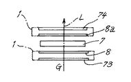
この点に鑑みて、図9に示すように、液晶パネル(7)と入出射側の偏光板(73)(74)との間に、厚み方向に沿って液晶分子(58)を配列した光学補償シート(8)(8a)を設けることが提案されている(例えば、非特許文献1参照)。これは内部にディスコティック液晶化合物からなる略円盤状の液晶分子(58)を配向した透明シートである。ここでディスコティック液晶化合物とは、ベンゼン環を核としてエステル分子が積層された化合物である。
該液晶分子(58)のチルト角度は、シートの厚み方向に沿って連続的に変化し、最も外側の液晶分子(58)は略水平に配備される。これにより、液晶パネル(7)内の液晶分子(57)の複屈折を補償し、液晶パネル(7)から漏れた光は偏光板(74)を通過しない。従って、液晶パネル(7)上に黒色が完全に黒く写り、コントラストを際立たせることができる。
この光学補償シート(8)(8a)は、偏光板(73)(74)に貼り付けられることが多い。光学補償シート(8)(8a)内の液晶分子(58)の配向方向は、表示基板(70)(71)の配向方向と平行である必要がある。
【0006】
【特許文献1】
特開2000−39591号(第5図)
【0007】
【非特許文献1】
富士写真フィルム株式会社技術レポート1998年第2号97−98頁
【0008】
【発明が解決しようとする課題】
光学補償シート(8)(8a)は、液晶分子(58)の配向方向が表示基板(70)(71)の配向方向と平行であるように、偏光板(73)(74)に貼り付けられるべきである。
しかし、光学補償シート(8)(8a)の偏光板(73)(74)に対する取り付け誤差により、光学補償シート(8)(8a)の液晶分子(58)の配向方向が配向方向とは平行にならない場合がある。
また、光学補償シート(8)は図10に示すように、フィルムシート(85)から必要な大きさに切り出されるものであるが、この切出し線が点線で示すように、誤って正規の位置からずれる場合がある。
このような光学補償シート(8)は、液晶分子(58)の配向方向が本来の位置からずれているから、本来遮断すべき光も通過させ、その結果、本来黒色で表示される部分に部分的に光漏れが生じ、表示ムラとなる。また、光学補償シート(8)は固定であったので、コントラスト低下や表示ムラが発生した場合は、異なる光学軸を有する別の光学補償シート(8)と交換していた。従って、種々の光学軸を有する光学補償シート(8)を揃える必要が生じ、不要在庫の発生等の弊害を招来していた。
出願人は、光軸に直交する面内にて、光学補償シート(8)の液晶分子(58)の配向方向を回動調整することにより、黒色と白色のコントラストが明確で均一な画像を写し出すことを着想した。
本発明は、光学補償シート(8)を配備した投写装置にて、黒色と白色のコントラストがはっきりした均一な画像を写し出す装置を提供することを目的とする。
【0009】
【課題を解決する為の手段】
光源(35)からの光に照射され液晶分子(57)を封入したノーマリーホワイトタイプの液晶パネル(7)と、該液晶パネル(7)に対向した偏光板(73)と、液晶パネル(7)と偏光板(73)との間に光学補償シート(8)を配備した投写装置に於いて、前記光学補償シート(7)は、シャーシ(3)上に設けられた回動調整機構(1)に取り付けられると共に、回動調整機構(1)は、光軸Lに直交する面内にて回動調整可能に設けられ、液晶パネル(7)に電界が印加された状態における、液晶パネル(7)を透過する光の液晶分子(57)による複屈折は、光学補償シート(7)の回動調整によって補償可能に構成されている。
前記回動調整機構(1)は、光学補償シート(8)が取り付けられる第1回動板(2)と、偏光板(73)が取り付けられる第2回動板(6)を具え、両回動板(2)(6)は互いに離間して対向し、一方の回動板から突出したガイド軸(60)(60)が他方の回動板に開設された孔(20)に嵌まって、互いに独立して回動調整される。
【0010】
【作用及び効果】
光学補償シート(8)は光軸Lに直交する面内にて、回動調整されるから、光学補償シート(8)内の液晶分子(58)の配向方向を、液晶パネル(7)の配向方向と厳密に平行に設定できる。これにより、黒色と白色のコントラストがはっきりした均一な画像を写し出すことができる。
また、回動調整機構(1)を構成する第1回動板(2)と、第2回動板(6)は、独立して別々に調整されるから、一方の回動板を調整しても、他方の回動板の調整がずれることはなく、調整が安定してできる。
【0011】
【発明の実施の形態】
以下、本発明の一例を図を用いて詳述する。
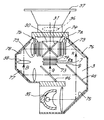
図1は、本例に係わる投写装置の平面図である。装置は、シャーシ(3)上に光の3原色であるR、G、Bに対応した3枚の液晶パネル(7)(7a)(7b)を具え、これらを光源(35)からの強い光で照射し、液晶パネルを通過した光束を合成して、画像を映し出す。本例にあっては、光学補償シート(8)の回動調整に特徴があるが、先ず全体構成を説明する。
シャーシ(3)内には、投写レンズ(36)の光軸を挟んで、RとBに対応した液晶パネル(7a)(7b)が配備され、両液晶パネル(7a)(7b)の間にプリズム体(30)が配備される。プリズム体(30)を挟んで投写レンズ(36)の反対側には、Gに対応した液晶パネル(7)が設けられている。
シャーシ(3)への光路入口には、光源(35)が配備され、光路上には全反射ミラー(75)(76)(77)(78)、ダイクロイックミラー(45)(46)が光路に対して傾いて配備されている。
【0012】
光源(35)からの光は、全反射ミラー(75)により反射された後に、ダイクロイックミラー(45)がRの通過を許し、GとBを反射する。Rは全反射ミラー(76)により反射されてRに対応した液晶パネル(7a)を照射し、プリズム体(30)により、投写レンズ(36)に向けて照射される。Gはダイクロイックミラー(46)に反射されてプリズム体(30)に入射し、該入射光はそのままプリズム体(30)を通過し、投写レンズ(36)に入射する。Bはリレーレンズ(38)を経て全反射ミラー(77)により反射された後に、プリズム体(30)内の合成ミラー(31)に反射されて投写レンズ(36)に入射し、スクリーン(37)に照射される。
【0013】
図2は、Gに対応した液晶パネル(7)の周囲の拡大平面図である。尚、R、Bに対応した液晶パネル(7a)(7b)の周囲も、Gに対応した液晶パネル(7)の周囲と同様の構成となっているが、説明の便宜上、Gに対応した液晶パネル(7)を例示する。
液晶パネル(7)の光入射側と出射側には、夫々偏光板(73)(74)が配備され、周知の如く、入射側の偏光板(73)を通過した一方の偏光(仮にP波とする)は、液晶パネル(7)に電界が印加されない状態で、液晶パネル(7)内にてねじられて、P波に直交したS波に偏光角を変えられて、出射側の偏光板(74)を通過する。
液晶パネル(7)と入射側偏光板(73)との間には、入射側光学補償シート(8)が、液晶パネル(7)と出射側偏光板(74)との間には、出射側光学補償シート(8a)が夫々配備される。
入射側偏光板(73)と入射側光学補償シート(8)、及び出射側偏光板(74)と出射側光学補償シート(8a)は、夫々回動調整機構(1)(1)に取り付けられて、光軸Lに直交する面内にて回動調整される。
【0014】
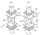
図3は、入射側偏光板(73)と入射側光学補償シート(8)が取り付けられる回動調整機構(1)の分解斜視図である。尚、出射側偏光板(74)と出射側光学補償シート(8a)も同じ構成の回動調整機構(1)に取り付けられる。
回動調整機構(1)は、薄いガラス板(図示せず)に貼り付けられた光学補償シート(8)が取り付けられる第1回動板(2)と、偏光板(73)が取り付けられる第2回動板(6)を具え、後記の如く、両回動板(2)(6)は夫々独立して回動調整される。回動調整機構(1)は、シャーシ(3)上に立てて設けられた壁片(4)に取り付けられる。
第1回動板(2)は、高さ方向の略中央部に、光学補償シート(8)が嵌まる透孔(21)を開設し、上端部に2つの円弧孔(20)(20)を開設している。円弧孔(20)(20)の一端部は円弧孔(20)(20)の上下幅よりも大きな膨み部(20a)(20a)を形成している。
第1回動板(2)の下端部には、切欠き(22)が設けられている。第1回動板(2)上にて円弧孔(20)(20)の上方からは、上向きに略円弧状で膨らんだ第1突板(23)が壁片(4)に向けて突出し、該第1突板(23)には左右に延びた第1長孔(24)が開設されている。第1回動板(2)の右端部は上向きに延びて、調整作業者の指が触れる摘み部(25)を形成している。
【0015】
第2回動板(6)は、高さ方向の略中央部に、偏光板(73)が嵌まる透孔(61)を開設し、上端部から2本のガイド軸(60)(60)が第1回動板(2)に向けて突出している。第2回動板(6)の下端部には、2箇所の切欠き(62)(62)が開設されている。第2回動板(6)上にて透孔(61)の下方からは、回動支持軸(63)が第1回動板(2)に向けて突出している。
ガイド軸(60)(60)及び回動支持軸(63)には、周方向に沿って溝(67)(67)が形成されている。第1回動板(2)は膨み部(20a)がガイド軸(60)(60)に挿入されてから、円弧孔(20)(20)の周縁部が溝(67)(67)(67)に嵌まる(図5参照)。また、第1回動板(2)の切欠き(22)が、回動支持軸(63)の溝(67)に嵌まる。これにより、第1回動板(2)と第2回動板(6)との間隔は一定に保たれる。
第2回動板(6)上にてガイド軸(60)(60)の上方からは、上向きに円弧状で膨らんだ第2突板(64)が壁片(4)に向けて突出し、該第2突板(64)には、第2長孔(65)、及び2つの第3長孔(66)(66)が開設されている。第2回動板(6)の右端部は上向きに延びて、調整作業者の指が触れる摘み部(68)を形成している。
第1回動板(2)は回動支持軸(63)を中心に、光軸Lに直交する面内にて回動し、円弧孔(20)(20)がガイド軸(60)(60)に嵌まって、回動を案内される。また、第1突板(23)が第2突板(64)に重なり、第1長孔(24)が第2長孔(65)に重なる。
【0016】
壁片(4)は、高さ方向の中央部に光が通過する透孔(44)を開設し、上端面に突軸(40)(40)及びネジ穴(41)を設けている。壁片(4)の下端部からは受け片(42)(42)が突出し、シャーシ(3)上にて該受け片(42)(42)の下方には凹溝(43)が形成されている。第2回動板(6)の下端部は、凹溝(43)に嵌まる。受け片(42)(42)には、第2回動板(6)の切欠き(62)(62)が嵌まり、第2回動板(6)は何れか一方の受け片(42)(42)を中心に、光軸Lに直交する面内にて回動する。
受け片(42)と切欠き(62)の間は、左右に隙間を設けており、第2回動板(6)の回動を許す。突軸(40)(40)は、第2回動板(6)の第3長孔(66)(66)に嵌まり、第2回動板(6)の回動を案内する。
【0017】
(偏光板の回動調整)
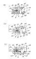
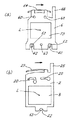
図4(a)、(b)、(c)は、調整動作を示す平面図であり、図6(a)、(b)は夫々、第2回動板、第1回動板の回動状態を夫々示す正面図である。図4(a)に示すように、第1長孔(24)と第2長孔(65)とが重なった状態で、上方から止めネジ(26)が両長孔(24)(25)を貫通して、壁片(4)上のネジ穴(41)に螺合する。
偏光板(73)を回動調整するには、第2回動板(6)を回動させる。止めネジ(26)を緩めて、第2回動板(6)の摘み部(68)を指で上から摘み、図4(b)に示すように、第2回動板(6)を右に動かす。勿論、左に動かしてもよい。図3に示すように、第2回動板(6)は切欠き(62)(62)が受け片(42)(42)に嵌まっているから、図6(a)に示すように、受け片(42)(42)と切欠き(62)(62)の周縁部との接点を中心に、光軸Lに直交する面内にて回動する。このとき、第1回動板(2)は回動しない。回動調整終了後は、止めネジ(26)を締める。
【0018】
(光学補償シートの回動調整)
光学補償シート(8)を回動調整するには、第1回動板(2)を回動させる。止めネジ(26)を緩めて、第1回動板(2)の摘み部(25)を指で上から摘み、図4(c)に示すように、第2回動板(6)を右に動かす。勿論、左に動かしてもよい。図3に示すように、第1回動板(2)は切欠き(22)が回動支持軸(63)に嵌まっているから、図6(b)に示すように、該回動支持軸(63)を中心に、光軸Lに直交する面内にて回動する。このとき、第2回動板(6)は回動しない。回動調整終了後は、止めネジ(26)を締める。
即ち、第1回動板(2)と第2回動板(6)は別々に動き、互いに連動しない。また、両回動板(2)(6)は上から調整される。これによって、調整作業が安定し且つ楽になる。尚、両回動板(2)(6)の上方から治具(図示せず)を挿入して調整してもよい。
【0019】
光学補償シート(8)は光軸Lに直交する面内にて、回動調整されるから、光学補償シート(8)内の液晶分子(58)の配向方向を、液晶パネル(7)の配向方向と厳密に平行に設定できる。これにより、黒色と白色のコントラストがはっきりした均一な画像を写し出すことができる。また、従来のように、種々の光学軸を有する光学補償シート(8)を揃える必要がなく、不要在庫の発生等の弊害を解消できる。
尚、光学補償シート(8)の回動調整は、光源(35)を発光させて、投写レンズ(36)を通して画像をスクリーン(37)に表示させ、この画像の黒色と白色のコントラストがはっきりするように、両回動板(2)(6)を回転させて光学補償シート(8)及び偏光板(73)を調整する。
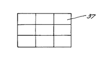
出願人は、光学補償シート(8)(8a)及び偏光板(73)(74)の回動調整後に、黒色と白色のコントラスト比を求めて、本発明の効果を確認した。先ず光源(35)を発光させて、且つ液晶パネル(7)に電界を印加せず、スクリーン(37)に白色を表示させる。図7に示すように、スクリーン(37)上の画面を9分割して、各分割画面の中央部の照度を測定した。9つの画面の照度(単位:LUX)の平均値を求め、この平均値をWaveとする。
【0020】
次に、液晶パネル(7)に電界を印加して、スクリーン(37)に黒色を表示させる。上記同様に、スクリーン(37)上の画面を9分割して、各分割画面の中央部の照度を測定した。9つの画面の照度の平均値を求め、この平均値をBRaveとする。
このWaveとBRaveの比を求めたところ、約800:1であった。光学補償シート(8)(8a)を液晶パネル(7)の前後に挿入しない場合は、WaveとBRaveの比は、約400:1であったから、黒色と白色のコントラストを向上させることができた。
上記実施例では、液晶パネル(7)の入射側と出射側の両方に、光学補償シート(8)(8a)を設けているが、入射側と出射側の何れか一方に設けてもよい。
また、光学補償シート(8)の回動調整機構は、図3の構成に限定されるものではなく、例えば従来技術である特開2000−39591号に開示された調整機構を用いてもよい。
更に、上記実施例では光軸Lに直交する面内での回動調整について説明したが、光軸Lから傾いた面内での回動調整についても十分な効果が得られる。
【0021】
上記実施例の説明は、本発明を説明するためのものであって、特許請求の範囲に記載の発明を限定し、或は範囲を減縮する様に解すべきではない。又、本発明の各部構成は上記実施例に限らず、特許請求の範囲に記載の技術的範囲内で種々の変形が可能であることは勿論である。
上記例では、ガイド軸(60)(60)が第2回動板(6)から突出し、円弧孔(20)(20)が第1回動板(2)に開設されているとしたが、ガイド軸(60)(60)が第1回動板(2)から突出し、円弧孔(20)(20)が第2回動板(6)に開設されていてもよい。また、本発明の構成は、電界が印加されない状態で、黒く写る所謂ノーマリブラックの液晶パネル(7)にも適用できる。
【図面の簡単な説明】
【図1】投写装置の平面図である。
【図2】Gに対応した液晶パネルの周囲の拡大平面図である。
【図3】入射側偏光板と入射側光学補償シートが取り付けられる回動調整機構の分解斜視図である。
【図4】(a)、(b)、(c)は、調整動作を示す平面図である。
【図5】溝に第1回動板が嵌まった状態を、図3のB方向から見た断面図である。
【図6】(a)は第2回動板の回動状態を、(b)は第1回動板の回動状態を夫々示す正面図である。
【図7】スクリーンの正面図である。
【図8】(a)、(b)は、液晶パネルと偏光板の分解斜視図であり、(a)は液晶パネルに電界が印加されない状態を、(b)は液晶パネルに電界が印加された状態を夫々示す。
【図9】図8の液晶パネルをA方向から見た正面図であり、光学補償シートを貼り付けている。
【図10】フィルムシートから光学補償シートを切り出す状態を示す図である。
【符号の説明】
(1) 回動調整機構
(2) 第1回動板
(3) シャーシ
(6) 第2回動板
(7) 液晶パネル
(8) 光学補償シート
(35) 光源
(73) 偏光板[0001]
BACKGROUND OF THE INVENTION
The present invention relates to a projection apparatus in which an optical compensation sheet is provided between a liquid crystal panel and a polarizing plate.
[0002]
[Prior art]
FIGS. 8A and 8B are exploded perspective views of the liquid crystal panel 7 and the polarizing
The liquid crystal panel (7) is configured by enclosing liquid crystal molecules (57) in transparent display substrates (70) and (71), and both display substrates (70) and (71) are rubbed to form both display substrates (70 and 70). ) (71), the rod-like liquid crystal molecules (57) are confined in a twisted state.
[0003]
The liquid crystal panel (7) is a so-called normally white type. When no electric field is applied between the display substrates (70) and (71), as shown in FIG. The polarized light that has passed passes through the polarizing plate (74) on the emission side while being bent 90 degrees by the twist of the liquid crystal molecules (57). Accordingly, the liquid crystal panel (7) is displayed brightly, that is, white.
When an electric field is applied between the display substrates (70) and (71), as shown in FIG. 8 (b), the liquid crystal molecules (57) are aligned and polarized light that has passed through the polarizing plate (73) on the incident side. Passes through the gap between the liquid crystal molecules (57). Since the polarized light is blocked by the output-side polarizing plate (74), it is displayed in black on the liquid crystal panel (7). The liquid crystal panel (7) displays an image by switching the presence or absence of an electric field for each small space.
[0004]
However, in reality, in the liquid crystal panel (7), the tilt angle of the liquid crystal molecules (57) is set to the liquid crystal panel (70) as shown in FIG. 9 with an electric field applied between the display substrates (70) and (71). It is known that it changes continuously along the thickness direction of 7). As a result, when an electric field is applied between the display substrates (70) and (71), light leaks due to the birefringence of the liquid crystal molecules (57) located near the substrates (70) and (71). Is known to decrease.
In recent years, there has been a demand for higher density images. In an apparatus that captures such a high-density image, it is necessary to highlight the black and white contrast of the projected image and to capture the image clearly. As described above, when the polarized light that should be blocked normally passes through the liquid crystal panel (7) as shown by the alternate long and short dash line in FIG. 8 (b) due to the birefringence of the liquid crystal molecules (57), the black color is not displayed completely black. . Here, birefringence means that the traveling speed varies depending on the direction of the vibration plane of light, and an azimuth with a high speed is called a fast axis and a slow azimuth is called a slow axis.
[0005]
In view of this point, as shown in FIG. 9, an optical device in which liquid crystal molecules (58) are arranged along the thickness direction between the liquid crystal panel (7) and the input and output side polarizing plates (73) and (74). It has been proposed to provide the compensation sheets (8) and (8a) (see, for example, Non-Patent Document 1). This is a transparent sheet in which substantially disc-shaped liquid crystal molecules (58) made of a discotic liquid crystal compound are aligned. Here, the discotic liquid crystal compound is a compound in which ester molecules are stacked with a benzene ring as a nucleus.
The tilt angle of the liquid crystal molecules (58) changes continuously along the thickness direction of the sheet, and the outermost liquid crystal molecules (58) are arranged substantially horizontally. Thereby, the birefringence of the liquid crystal molecules (57) in the liquid crystal panel (7) is compensated, and the light leaking from the liquid crystal panel (7) does not pass through the polarizing plate (74). Therefore, the black color appears completely black on the liquid crystal panel (7), so that the contrast can be emphasized.
The optical compensation sheets (8) and (8a) are often attached to the polarizing plates (73) and (74). The alignment direction of the liquid crystal molecules (58) in the optical compensation sheets (8) and (8a) needs to be parallel to the alignment directions of the display substrates (70) and (71).
[0006]
[Patent Document 1]
JP 2000-39591 (FIG. 5)
[0007]
[Non-Patent Document 1]
Fuji Photo Film Co., Ltd. Technical Report 1998 No. 2 pages 97-98 [0008]
[Problems to be solved by the invention]
The optical compensation sheets (8) and (8a) are attached to the polarizing plates (73) and (74) so that the alignment direction of the liquid crystal molecules (58) is parallel to the alignment direction of the display substrates (70) and (71). Should.
However, the alignment direction of the liquid crystal molecules (58) of the optical compensation sheets (8) and (8a) is parallel to the alignment direction due to an attachment error of the optical compensation sheets (8) and (8a) to the polarizing plates (73) and (74). It may not be possible.
Further, as shown in FIG. 10, the optical compensation sheet (8) is cut out from the film sheet (85) to a required size. There may be deviation.
Such an optical compensation sheet (8) allows the light to be originally blocked to pass through because the alignment direction of the liquid crystal molecules (58) is deviated from the original position. As a result, light leaks and display unevenness occurs. Further, since the optical compensation sheet (8) was fixed, when contrast reduction or display unevenness occurred, it was replaced with another optical compensation sheet (8) having a different optical axis. Therefore, it is necessary to prepare the optical compensation sheet (8) having various optical axes, which causes adverse effects such as generation of unnecessary inventory.
The applicant projects an image with clear and uniform contrast between black and white by rotating and adjusting the alignment direction of the liquid crystal molecules (58) of the optical compensation sheet (8) in a plane perpendicular to the optical axis. I was inspired by that.
An object of the present invention is to provide an apparatus for projecting a uniform image with clear contrast between black and white in a projection apparatus provided with an optical compensation sheet (8).
[0009]
[Means for solving the problems]
A normally white type liquid crystal panel (7) which is irradiated with light from a light source (35) and encloses liquid crystal molecules (57), a polarizing plate (73) facing the liquid crystal panel (7), and a liquid crystal panel (7 ) And the polarizing plate (73), the optical compensation sheet (7) is provided with a rotation adjusting mechanism (1) provided on the chassis (3). ) And the rotation adjustment mechanism (1) is provided so as to be adjustable in a plane orthogonal to the optical axis L, and the liquid crystal panel (7) in the state where an electric field is applied to the liquid crystal panel (7). The birefringence of the light transmitted through 7) due to the liquid crystal molecules (57) can be compensated by adjusting the rotation of the optical compensation sheet (7).
The rotation adjustment mechanism (1) includes a first rotation plate (2) to which an optical compensation sheet (8) is attached and a second rotation plate (6) to which a polarizing plate (73) is attached. The moving plates (2) and (6) face each other apart from each other, and the guide shafts (60) and (60) protruding from one rotating plate are fitted in the holes (20) formed in the other rotating plate. The rotation is adjusted independently of each other.
[0010]
[Action and effect]
Since the optical compensation sheet (8) is rotated and adjusted in a plane orthogonal to the optical axis L, the orientation direction of the liquid crystal molecules (58) in the optical compensation sheet (8) is set to the orientation of the liquid crystal panel (7). Can be set exactly parallel to the direction. Thereby, a uniform image with clear contrast between black and white can be displayed.
Moreover, since the 1st rotation board (2) and 2nd rotation board (6) which comprise a rotation adjustment mechanism (1) are adjusted separately independently, one rotation board is adjusted. However, the adjustment of the other rotating plate is not shifted, and the adjustment can be made stably.
[0011]
DETAILED DESCRIPTION OF THE INVENTION
Hereinafter, an example of the present invention will be described in detail with reference to the drawings.
FIG. 1 is a plan view of a projection apparatus according to this example. The device comprises three liquid crystal panels (7), (7a) and (7b) corresponding to R, G and B which are the three primary colors of light on the chassis (3), and these are used as strong light from the light source (35). The image is projected by synthesizing the light flux that has passed through the liquid crystal panel. This example is characterized by the rotation adjustment of the optical compensation sheet (8). First, the overall configuration will be described.
In the chassis (3), there are disposed liquid crystal panels (7a) and (7b) corresponding to R and B across the optical axis of the projection lens (36), and between the liquid crystal panels (7a) and (7b). A prism body (30) is provided. A liquid crystal panel (7) corresponding to G is provided on the opposite side of the projection lens (36) across the prism body (30).
A light source (35) is provided at the entrance of the optical path to the chassis (3), and total reflection mirrors (75) (76) (77) (78) and dichroic mirrors (45) (46) are in the optical path on the optical path. It is inclined and deployed.
[0012]
After the light from the light source (35) is reflected by the total reflection mirror (75), the dichroic mirror (45) allows the passage of R and reflects G and B. R is reflected by the total reflection mirror (76) and irradiates the liquid crystal panel (7a) corresponding to R, and is irradiated toward the projection lens (36) by the prism body (30). G is reflected by the dichroic mirror (46) and enters the prism body (30), and the incident light passes through the prism body (30) as it is and enters the projection lens (36). B is reflected by the total reflection mirror (77) through the relay lens (38), then is reflected by the composite mirror (31) in the prism body (30) and is incident on the projection lens (36), and the screen (37). Is irradiated.
[0013]
FIG. 2 is an enlarged plan view of the periphery of the liquid crystal panel (7) corresponding to G. Note that the periphery of the liquid crystal panels (7a) and (7b) corresponding to R and B has the same configuration as the periphery of the liquid crystal panel (7) corresponding to G. A panel (7) is illustrated.
Polarizers (73) and (74) are respectively provided on the light incident side and the exit side of the liquid crystal panel (7), and, as is well known, one polarized light (tentatively P wave) that has passed through the incident side polarizing plate (73). Is twisted in the liquid crystal panel (7) in a state where no electric field is applied to the liquid crystal panel (7), and the polarization angle is changed to an S wave orthogonal to the P wave, so that the polarizing plate on the output side Go through (74).
An incident side optical compensation sheet (8) is provided between the liquid crystal panel (7) and the incident side polarizing plate (73), and an outgoing side is provided between the liquid crystal panel (7) and the outgoing side polarizing plate (74). Optical compensation sheets (8a) are respectively provided.
The incident side polarizing plate (73) and the incident side optical compensation sheet (8), and the outgoing side polarizing plate (74) and the outgoing side optical compensation sheet (8a) are attached to the rotation adjusting mechanisms (1) and (1), respectively. Thus, the rotation is adjusted in a plane orthogonal to the optical axis L.
[0014]
FIG. 3 is an exploded perspective view of the rotation adjusting mechanism (1) to which the incident side polarizing plate (73) and the incident side optical compensation sheet (8) are attached. The exit side polarizing plate (74) and the exit side optical compensation sheet (8a) are also attached to the rotation adjustment mechanism (1) having the same configuration.
The rotation adjustment mechanism (1) includes a first rotation plate (2) to which an optical compensation sheet (8) attached to a thin glass plate (not shown) is attached, and a first plate to which a polarizing plate (73) is attached. Two rotating plates (6) are provided, and both the rotating plates (2) and (6) are independently rotated and adjusted as described later. The rotation adjusting mechanism (1) is attached to a wall piece (4) provided upright on the chassis (3).
The first rotating plate (2) has a through hole (21) into which the optical compensation sheet (8) is fitted at a substantially central portion in the height direction, and two arc holes (20) (20) at the upper end. Has been established. One end of each of the arc holes (20) and (20) forms a bulging portion (20a) and (20a) larger than the vertical width of the arc holes (20) and (20).
A notch (22) is provided at the lower end of the first rotating plate (2). From above the arc holes (20), (20) on the first rotating plate (2), the first projecting plate (23) swelled upward in a substantially arc shape protrudes toward the wall piece (4), The first projecting plate (23) is provided with a first elongated hole (24) extending left and right. The right end portion of the first rotating plate (2) extends upward to form a knob portion (25) that is touched by the finger of the adjusting operator.
[0015]
The second rotating plate (6) has a through hole (61) into which the polarizing plate (73) is fitted at a substantially central portion in the height direction, and two guide shafts (60) (60) from the upper end. Protrudes toward the first rotating plate (2). Two notches (62) and (62) are formed at the lower end of the second rotating plate (6). On the second rotating plate (6), from below the through hole (61), a rotating support shaft (63) protrudes toward the first rotating plate (2).
Grooves (67) and (67) are formed in the guide shafts (60) and (60) and the rotation support shaft (63) along the circumferential direction. In the first rotating plate (2), after the bulging portion (20a) is inserted into the guide shaft (60) (60), the peripheral edge portion of the circular hole (20) (20) is the groove (67) (67) ( 67) (see FIG. 5). Further, the notch (22) of the first rotation plate (2) is fitted into the groove (67) of the rotation support shaft (63). Thereby, the space | interval of a 1st rotation board (2) and a 2nd rotation board (6) is kept constant.
From above the guide shafts (60) and (60) on the second rotating plate (6), a second projecting plate (64) bulging upward in an arc shape projects toward the wall piece (4). The second projecting plate (64) is provided with a second long hole (65) and two third long holes (66) and (66). The right end of the second rotating plate (6) extends upward to form a knob (68) that is touched by the adjustment operator's finger.
The first rotating plate (2) rotates about a rotation support shaft (63) in a plane perpendicular to the optical axis L, and the circular holes (20), (20) are guided by the guide shafts (60), (60). ) And guided to turn. The first projecting plate (23) overlaps the second projecting plate (64), and the first elongated hole (24) overlaps the second elongated hole (65).
[0016]
The wall piece (4) has a through hole (44) through which light passes at the center in the height direction, and has a projecting shaft (40) (40) and a screw hole (41) on the upper end surface. The receiving pieces (42) and (42) protrude from the lower end of the wall piece (4), and a concave groove (43) is formed below the receiving pieces (42) and (42) on the chassis (3). Yes. The lower end of the second rotating plate (6) is fitted into the groove (43). The notches (62) and (62) of the second rotating plate (6) are fitted into the receiving pieces (42) and (42), and the second rotating plate (6) is one of the receiving pieces (42). It rotates in a plane perpendicular to the optical axis L, centering on (42).
A gap is provided between the receiving piece (42) and the notch (62) on the left and right to allow the second rotating plate (6) to rotate. The projecting shafts (40) and (40) are fitted into the third elongated holes (66) and (66) of the second rotating plate (6) to guide the rotation of the second rotating plate (6).
[0017]
(Rotation adjustment of polarizing plate)
4 (a), 4 (b), and 4 (c) are plan views showing the adjustment operation, and FIGS. 6 (a) and 6 (b) are the rotations of the second rotating plate and the first rotating plate, respectively. It is a front view which shows a state, respectively. As shown in FIG. 4 (a), with the first elongated hole (24) and the second elongated hole (65) overlapped, the set screw (26) is inserted into the elongated holes (24), (25) from above. It penetrates and is screwed into the screw hole (41) on the wall piece (4).
In order to adjust the rotation of the polarizing plate (73), the second rotating plate (6) is rotated. Loosen the set screw (26), pick the knob (68) of the second rotating plate (6) from above with your finger, and move the second rotating plate (6) to the right as shown in FIG. 4 (b). Move to. Of course, you may move it to the left. As shown in FIG. 6 (a), the second rotating plate (6) has the notches (62) and (62) fitted into the receiving pieces (42) and (42). It rotates in a plane perpendicular to the optical axis L around the contact point between the receiving pieces (42) and (42) and the peripheral portions of the notches (62) and (62). At this time, the first rotating plate (2) does not rotate. After completing the rotation adjustment, tighten the set screw (26).
[0018]
(Rotation adjustment of optical compensation sheet)
In order to adjust the rotation of the optical compensation sheet (8), the first rotation plate (2) is rotated. Loosen the set screw (26), pick the knob (25) of the first rotating plate (2) from above with your finger, and move the second rotating plate (6) to the right as shown in FIG. 4 (c). Move to. Of course, you may move it to the left. As shown in FIG. 3, the notch (22) of the first rotating plate (2) is fitted in the rotating support shaft (63). Therefore, as shown in FIG. It rotates in a plane perpendicular to the optical axis L around the axis (63). At this time, the second rotating plate (6) does not rotate. After completing the rotation adjustment, tighten the set screw (26).
That is, the first rotating plate (2) and the second rotating plate (6) move separately and do not interlock with each other. Further, both the rotating plates (2) and (6) are adjusted from above. This makes adjustment work stable and easy. In addition, you may adjust by inserting a jig | tool (not shown) from the upper direction of both rotation board (2) (6).
[0019]
Since the optical compensation sheet (8) is rotated and adjusted in a plane orthogonal to the optical axis L, the orientation direction of the liquid crystal molecules (58) in the optical compensation sheet (8) is set to the orientation of the liquid crystal panel (7). Can be set exactly parallel to the direction. Thereby, a uniform image with clear contrast between black and white can be displayed. Further, unlike the conventional case, it is not necessary to prepare the optical compensation sheet (8) having various optical axes, and it is possible to eliminate problems such as generation of unnecessary inventory.
The rotation adjustment of the optical compensation sheet (8) causes the light source (35) to emit light and displays the image on the screen (37) through the projection lens (36), and the black and white contrast of this image is clear. As described above, the rotating plates (2) and (6) are rotated to adjust the optical compensation sheet (8) and the polarizing plate (73).
The applicant found the contrast ratio between black and white after adjusting the rotation of the optical compensation sheets (8), (8a) and the polarizing plates (73), (74), and confirmed the effect of the present invention. First, the light source (35) is caused to emit light, and an electric field is not applied to the liquid crystal panel (7), and white is displayed on the screen (37). As shown in FIG. 7, the screen on the screen (37) was divided into nine, and the illuminance at the center of each divided screen was measured. The average value of the illuminance (unit: LUX) of the nine screens is obtained, and this average value is defined as Wave.
[0020]
Next, an electric field is applied to the liquid crystal panel (7) to display black on the screen (37). Similarly to the above, the screen on the screen (37) was divided into nine, and the illuminance at the center of each divided screen was measured. The average value of the illuminance of the nine screens is obtained, and this average value is defined as BRave.
When the ratio of Wave to BRave was determined, it was about 800: 1. When the optical compensation sheets (8) and (8a) were not inserted before and after the liquid crystal panel (7), the ratio of Wave to BRave was about 400: 1, so that the contrast between black and white could be improved. .
In the above embodiment, the optical compensation sheets (8) and (8a) are provided on both the incident side and the outgoing side of the liquid crystal panel (7), but may be provided on either the incident side or the outgoing side.
Further, the rotation adjustment mechanism of the optical compensation sheet (8) is not limited to the configuration shown in FIG. 3, and for example, an adjustment mechanism disclosed in Japanese Patent Application Laid-Open No. 2000-39591 may be used.
Further, in the above-described embodiment, the rotation adjustment in the plane orthogonal to the optical axis L has been described. However, a sufficient effect can be obtained for the rotation adjustment in the plane inclined from the optical axis L.
[0021]
The above description of the embodiments is for explaining the present invention, and should not be construed as limiting the invention described in the claims or reducing the scope thereof. In addition, the configuration of each part of the present invention is not limited to the above embodiment, and various modifications can be made within the technical scope described in the claims.
In the above example, the guide shafts (60) and (60) protrude from the second rotating plate (6), and the arc holes (20) and (20) are opened in the first rotating plate (2). The guide shafts (60) and (60) may protrude from the first rotating plate (2), and the circular arc holes (20) and (20) may be provided in the second rotating plate (6). The configuration of the present invention can also be applied to a so-called normally black liquid crystal panel (7) that appears black when no electric field is applied.
[Brief description of the drawings]
FIG. 1 is a plan view of a projection apparatus.
FIG. 2 is an enlarged plan view of the periphery of a liquid crystal panel corresponding to G. FIG.
FIG. 3 is an exploded perspective view of a rotation adjusting mechanism to which an incident side polarizing plate and an incident side optical compensation sheet are attached.
FIGS. 4A, 4B, and 4C are plan views showing adjustment operations. FIGS.
5 is a cross-sectional view of the state in which the first rotating plate is fitted in the groove as viewed from the direction B of FIG.
6A is a front view showing a rotating state of a second rotating plate, and FIG. 6B is a front view showing a rotating state of the first rotating plate.
FIG. 7 is a front view of the screen.
FIGS. 8A and 8B are exploded perspective views of a liquid crystal panel and a polarizing plate, FIG. 8A shows a state where no electric field is applied to the liquid crystal panel, and FIG. 8B shows an electric field applied to the liquid crystal panel. Each state is shown.
FIG. 9 is a front view of the liquid crystal panel of FIG. 8 as viewed from the direction A, and an optical compensation sheet is pasted thereon.
FIG. 10 is a diagram illustrating a state in which an optical compensation sheet is cut out from a film sheet.
[Explanation of symbols]
(1) Rotation adjustment mechanism
(2) First rotating plate
(3) Chassis
(6) Second rotating plate
(7) LCD panel
(8) Optical compensation sheet
(35) Light source
(73) Polarizing plate
Claims (5)
前記光学補償シート(7)は、シャーシ(3)上に設けられた回動調整機構(1)に取り付けられると共に、回動調整機構(1)は、光軸Lに直交する面内にて回動調整可能に設けられ、液晶パネル(7)に電界が印加された状態における、液晶パネル(7)を透過する光の液晶分子(57)による複屈折は、光学補償シート(7)の回動調整によって補償可能に構成されていることを特徴とする投写装置。A normally white type liquid crystal panel (7) which is irradiated with light from a light source (35) and encloses liquid crystal molecules (57), a polarizing plate (73) facing the liquid crystal panel (7), and a liquid crystal panel (7 ) and at the projection device deployed optical Science compensation sheet (8) between the polarizing plate (73),
The optical compensation sheet (7) is Rutotomoni attached to the chassis (3) rotating adjusting mechanism provided on the (1), rotating adjusting mechanism (1), at plane perpendicular to the optical axis L The birefringence caused by the liquid crystal molecules (57) of the light transmitted through the liquid crystal panel (7) when the electric field is applied to the liquid crystal panel (7) is provided so that the rotation can be adjusted. A projection apparatus configured to be compensated by dynamic adjustment .
前記光学補償シート(7)は、シャーシ(3)上に設けられた回動調整機構(1)に取り付けられると共に、回動調整機構(1)は、光軸Lに直交する面内にて回動調整可能に設けられ、液晶パネル(7)に電界が印加された状態における、液晶パネル(7)を透過する光の液晶分子(57)による複屈折は、光学補償シート(7)の回動調整によって補償可能に構成されていることを特徴とする液晶パネルユニット。A normally white type liquid crystal panel (7) which is irradiated with light from a light source (35) and encloses liquid crystal molecules (57), a polarizing plate (73) facing the liquid crystal panel (7), and a liquid crystal panel (7 ) and at the liquid crystal panel unit deployed optical Science compensation sheet (8) between the polarizing plate (73),
The optical compensation sheet (7) is Rutotomoni attached to the chassis (3) rotating adjusting mechanism provided on the (1), rotating adjusting mechanism (1), at plane perpendicular to the optical axis L The birefringence caused by the liquid crystal molecules (57) of the light transmitted through the liquid crystal panel (7) when the electric field is applied to the liquid crystal panel (7) is provided so that the rotation can be adjusted. A liquid crystal panel unit configured to be compensated by dynamic adjustment .
Priority Applications (2)
| Application Number | Priority Date | Filing Date | Title |
|---|---|---|---|
| JP2002371510A JP3733112B2 (en) | 2002-12-24 | 2002-12-24 | Projection apparatus and liquid crystal panel unit used in the projection apparatus |
| US10/742,922 US7097306B2 (en) | 2002-12-24 | 2003-12-23 | Projection device and liquid crystal panel unit for use in the projection device |
Applications Claiming Priority (1)
| Application Number | Priority Date | Filing Date | Title |
|---|---|---|---|
| JP2002371510A JP3733112B2 (en) | 2002-12-24 | 2002-12-24 | Projection apparatus and liquid crystal panel unit used in the projection apparatus |
Related Child Applications (1)
| Application Number | Title | Priority Date | Filing Date |
|---|---|---|---|
| JP2005229671A Division JP3831742B2 (en) | 2005-08-08 | 2005-08-08 | Projection apparatus and liquid crystal panel unit used in the projection apparatus |
Publications (2)
| Publication Number | Publication Date |
|---|---|
| JP2004205593A JP2004205593A (en) | 2004-07-22 |
| JP3733112B2 true JP3733112B2 (en) | 2006-01-11 |
Family
ID=36954973
Family Applications (1)
| Application Number | Title | Priority Date | Filing Date |
|---|---|---|---|
| JP2002371510A Expired - Fee Related JP3733112B2 (en) | 2002-12-24 | 2002-12-24 | Projection apparatus and liquid crystal panel unit used in the projection apparatus |
Country Status (2)
| Country | Link |
|---|---|
| US (1) | US7097306B2 (en) |
| JP (1) | JP3733112B2 (en) |
Families Citing this family (17)
| Publication number | Priority date | Publication date | Assignee | Title |
|---|---|---|---|---|
| US20070056685A1 (en) * | 2003-09-18 | 2007-03-15 | Koninklijke Philips Electronics N.V. | Method to position a frame |
| JP4168899B2 (en) * | 2003-10-16 | 2008-10-22 | セイコーエプソン株式会社 | Optical component housing, optical device, and projector |
| JP4225954B2 (en) * | 2004-07-26 | 2009-02-18 | 三洋電機株式会社 | Projection device and liquid crystal panel unit used in projection device |
| JP4839623B2 (en) * | 2005-02-02 | 2011-12-21 | 株式会社日立製作所 | Projection-type image display device |
| JP4581769B2 (en) * | 2005-03-17 | 2010-11-17 | セイコーエプソン株式会社 | Prism structure and projector |
| JP4190529B2 (en) * | 2005-09-09 | 2008-12-03 | 三洋電機株式会社 | Projector device |
| JP4190546B2 (en) | 2006-05-02 | 2008-12-03 | 三洋電機株式会社 | LCD projector |
| JP4204604B2 (en) * | 2006-05-02 | 2009-01-07 | 三洋電機株式会社 | Projector device |
| JP2008089626A (en) | 2006-09-29 | 2008-04-17 | Seiko Epson Corp | Liquid crystal device and electronic device |
| JP2008268264A (en) * | 2007-04-16 | 2008-11-06 | Sanyo Electric Co Ltd | Liquid crystal display device |
| JP2009003106A (en) * | 2007-06-20 | 2009-01-08 | Sony Corp | Liquid crystal display |
| JP4703678B2 (en) * | 2008-04-09 | 2011-06-15 | 三洋電機株式会社 | Projector device |
| JP2008217028A (en) * | 2008-04-09 | 2008-09-18 | Sanyo Electric Co Ltd | Projector and liquid crystal panel unit to be used for the same |
| JP5115365B2 (en) * | 2008-07-04 | 2013-01-09 | セイコーエプソン株式会社 | Optical device and projector |
| JP5162625B2 (en) * | 2010-05-25 | 2013-03-13 | 三洋電機株式会社 | Projection device and liquid crystal panel unit used in projection device |
| JP5760185B2 (en) * | 2011-05-13 | 2015-08-05 | パナソニックIpマネジメント株式会社 | lighting equipment |
| JP6107043B2 (en) * | 2012-10-19 | 2017-04-05 | セイコーエプソン株式会社 | projector |
Family Cites Families (5)
| Publication number | Priority date | Publication date | Assignee | Title |
|---|---|---|---|---|
| JPH11160198A (en) * | 1997-12-02 | 1999-06-18 | Nec Corp | Liquid crystal initial alignment angle measuring method and device thereof |
| JP3454719B2 (en) | 1998-07-23 | 2003-10-06 | 三洋電機株式会社 | Projection device with polarizing plate |
| US6243065B1 (en) * | 1998-10-29 | 2001-06-05 | Agilent Technologies, Inc. | Reflective ferroelectric liquid crystal light valve with increased light throughput |
| US6301044B1 (en) * | 2000-03-30 | 2001-10-09 | Disney Enterprises, Inc. | Apparel color and image effect system |
| EP1160617B1 (en) * | 2000-05-31 | 2004-10-13 | Sony Corporation | Liquid crystal display projector with improved contrast |
-
2002
- 2002-12-24 JP JP2002371510A patent/JP3733112B2/en not_active Expired - Fee Related
-
2003
- 2003-12-23 US US10/742,922 patent/US7097306B2/en not_active Expired - Lifetime
Also Published As
| Publication number | Publication date |
|---|---|
| US7097306B2 (en) | 2006-08-29 |
| US20050134802A1 (en) | 2005-06-23 |
| JP2004205593A (en) | 2004-07-22 |
Similar Documents
| Publication | Publication Date | Title |
|---|---|---|
| JP3733112B2 (en) | Projection apparatus and liquid crystal panel unit used in the projection apparatus | |
| US7518662B2 (en) | Contrast enhancement for liquid crystal based projection systems | |
| JP3260867B2 (en) | Head-mounted display | |
| TWI427374B (en) | Retardation compensation element, van liquid crystal display device, and liquid crystal projector | |
| US6561649B1 (en) | Compact rear projection system using birefringent optics | |
| CN100510904C (en) | Liquid crystal projector | |
| EP2240814B1 (en) | A light modulator for optical image projection | |
| JP4661510B2 (en) | Projection display device and three-plate liquid crystal projector | |
| TW200837458A (en) | Reflective liquid crystal display device and reflective liquid crystal projector | |
| JP2001042314A (en) | LCD projector | |
| US7345724B2 (en) | Projector and liquid crystal panel unit for use in projector with optical sheet edge-tilting mechanism | |
| JP2002014345A (en) | Projection type liquid crystal display | |
| JP3831742B2 (en) | Projection apparatus and liquid crystal panel unit used in the projection apparatus | |
| JP4055465B2 (en) | projector | |
| TWI406081B (en) | Liquid crystal projector | |
| JP2001066598A (en) | Reflective liquid crystal display | |
| JP2009075460A (en) | Phase difference compensation element, liquid crystal display element, and projector | |
| JP3454719B2 (en) | Projection device with polarizing plate | |
| JP2008151844A (en) | Optical component adjustment mechanism, liquid crystal display and projection display | |
| JP2008276062A (en) | Liquid crystal display device | |
| WO2007021981A2 (en) | Contrast enhancement for liquid crystal based projection systems | |
| TWI292501B (en) | ||
| JPH0476517A (en) | Transmission type liquid crystal panel, polarized light source, and color projector | |
| JP2007086406A (en) | Liquid crystal display device, optical anisotropic body and method for producing the same | |
| JP2004053671A (en) | Projector using reflective liquid crystal element |
Legal Events
| Date | Code | Title | Description |
|---|---|---|---|
| A621 | Written request for application examination |
Free format text: JAPANESE INTERMEDIATE CODE: A621 Effective date: 20040810 |
|
| A871 | Explanation of circumstances concerning accelerated examination |
Free format text: JAPANESE INTERMEDIATE CODE: A871 Effective date: 20050510 |
|
| A975 | Report on accelerated examination |
Free format text: JAPANESE INTERMEDIATE CODE: A971005 Effective date: 20050524 |
|
| A131 | Notification of reasons for refusal |
Free format text: JAPANESE INTERMEDIATE CODE: A131 Effective date: 20050621 |
|
| A521 | Request for written amendment filed |
Free format text: JAPANESE INTERMEDIATE CODE: A523 Effective date: 20050808 |
|
| TRDD | Decision of grant or rejection written | ||
| A01 | Written decision to grant a patent or to grant a registration (utility model) |
Free format text: JAPANESE INTERMEDIATE CODE: A01 Effective date: 20050927 |
|
| A61 | First payment of annual fees (during grant procedure) |
Free format text: JAPANESE INTERMEDIATE CODE: A61 Effective date: 20051014 |
|
| R151 | Written notification of patent or utility model registration |
Ref document number: 3733112 Country of ref document: JP Free format text: JAPANESE INTERMEDIATE CODE: R151 |
|
| FPAY | Renewal fee payment (event date is renewal date of database) |
Free format text: PAYMENT UNTIL: 20081021 Year of fee payment: 3 |
|
| FPAY | Renewal fee payment (event date is renewal date of database) |
Free format text: PAYMENT UNTIL: 20091021 Year of fee payment: 4 |
|
| FPAY | Renewal fee payment (event date is renewal date of database) |
Free format text: PAYMENT UNTIL: 20101021 Year of fee payment: 5 |
|
| FPAY | Renewal fee payment (event date is renewal date of database) |
Free format text: PAYMENT UNTIL: 20111021 Year of fee payment: 6 |
|
| FPAY | Renewal fee payment (event date is renewal date of database) |
Free format text: PAYMENT UNTIL: 20111021 Year of fee payment: 6 |
|
| FPAY | Renewal fee payment (event date is renewal date of database) |
Free format text: PAYMENT UNTIL: 20121021 Year of fee payment: 7 |
|
| FPAY | Renewal fee payment (event date is renewal date of database) |
Free format text: PAYMENT UNTIL: 20121021 Year of fee payment: 7 |
|
| FPAY | Renewal fee payment (event date is renewal date of database) |
Free format text: PAYMENT UNTIL: 20131021 Year of fee payment: 8 |
|
| LAPS | Cancellation because of no payment of annual fees |