JP3731824B2 - Cooker - Google Patents
Cooker Download PDFInfo
- Publication number
- JP3731824B2 JP3731824B2 JP2003312563A JP2003312563A JP3731824B2 JP 3731824 B2 JP3731824 B2 JP 3731824B2 JP 2003312563 A JP2003312563 A JP 2003312563A JP 2003312563 A JP2003312563 A JP 2003312563A JP 3731824 B2 JP3731824 B2 JP 3731824B2
- Authority
- JP
- Japan
- Prior art keywords
- heating chamber
- cooking
- bottom plate
- protrusion
- side wall
- Prior art date
- Legal status (The legal status is an assumption and is not a legal conclusion. Google has not performed a legal analysis and makes no representation as to the accuracy of the status listed.)
- Expired - Lifetime
Links
- 238000010438 heat treatment Methods 0.000 claims description 165
- 238000010411 cooking Methods 0.000 claims description 118
- 239000000853 adhesive Substances 0.000 claims description 32
- 230000001070 adhesive effect Effects 0.000 claims description 27
- 235000013305 food Nutrition 0.000 claims description 24
- 238000005192 partition Methods 0.000 claims description 5
- 230000001105 regulatory effect Effects 0.000 claims description 5
- 230000000694 effects Effects 0.000 description 6
- 238000000034 method Methods 0.000 description 4
- 238000005452 bending Methods 0.000 description 3
- 239000000919 ceramic Substances 0.000 description 3
- 238000003780 insertion Methods 0.000 description 2
- 230000037431 insertion Effects 0.000 description 2
- 229910052710 silicon Inorganic materials 0.000 description 2
- 239000010703 silicon Substances 0.000 description 2
- 238000004026 adhesive bonding Methods 0.000 description 1
- 238000013459 approach Methods 0.000 description 1
- 238000004140 cleaning Methods 0.000 description 1
- 230000006866 deterioration Effects 0.000 description 1
- 239000003989 dielectric material Substances 0.000 description 1
- 239000000463 material Substances 0.000 description 1
- 239000002184 metal Substances 0.000 description 1
- 230000002093 peripheral effect Effects 0.000 description 1
- 238000003756 stirring Methods 0.000 description 1
- 239000002699 waste material Substances 0.000 description 1
- XLYOFNOQVPJJNP-UHFFFAOYSA-N water Substances O XLYOFNOQVPJJNP-UHFFFAOYSA-N 0.000 description 1
Images


Description
本発明は、加熱室底面に固定される底板を備えた加熱調理器の改良に関するものである。 The present invention relates to an improvement of a heating cooker provided with a bottom plate fixed to the bottom surface of a heating chamber.
従来の加熱調理器においては、マイクロ波を発振するマグネトロンを備え、このマグネトロンが発振したマイクロ波を加熱室内に供給し加熱室内の食品を加熱調理できるように構成されている。該加熱調理器の加熱室の下方にはモータにて回転する回転アンテナが設けられている。そして、マイクロ波を加熱室内に供給する際回転アンテナでマイクロ波を攪拌することにより加熱室内に収納した食品に均一にマイクロ波を当て、食品に加熱むらのない調理ができるように構成していた(特許文献1参照)。 A conventional cooking device includes a magnetron that oscillates microwaves, and is configured so that the microwaves oscillated by the magnetron can be supplied into the heating chamber to cook food in the heating chamber. A rotating antenna that is rotated by a motor is provided below the heating chamber of the cooking device. Then, when the microwave is supplied into the heating chamber, the microwave is uniformly applied to the food stored in the heating chamber by stirring the microwave with the rotating antenna, so that the food can be cooked without uneven heating. (See Patent Document 1).
また、加熱室内の底部にはセラミック等の電波を透過し易い材質の底板を設けて回転アンテナに手が触れないように回転アンテナを覆うと共に、この底板の上に食品などを載せる調理皿を載置可能に構成していた。この底板は、シリコン等の接着剤で全周を加熱室底面に固定していた。これにより、食品のカスや水分等が回転アンテナ部に入り込まないように構成していた。 In addition, a bottom plate made of a material that easily transmits radio waves, such as ceramics, is provided at the bottom of the heating chamber to cover the rotating antenna so that the hand does not touch the rotating antenna, and a cooking dish on which food or the like is placed is placed on the bottom plate. It was configured to be placeable. This bottom plate was fixed to the bottom surface of the heating chamber with an adhesive such as silicon. Thereby, it was comprised so that the waste of a foodstuff, a water | moisture content, etc. may not enter a rotation antenna part.
また、加熱室の側面に調理皿を載置するための載置棚を複数段設け、必要に応じて調理皿の高さを調整できる加熱調理器もあった。
There is also a heating cooker in which a plurality of mounting shelves for mounting cooking dishes are provided on the side of the heating chamber, and the height of the cooking dishes can be adjusted as necessary.
しかしながら、従来の加熱調理器で食品を調理する際、食品を載せた調理皿を底板上に載置し加熱室奥側にスライドすることにより調理皿を加熱室内にセットしているが、底板全周を固定している接着剤はどうしても底板よりも盛り上ってしまう。このため、調理皿のスライド時に調理皿が接着剤に当たって調理皿の摺動性が悪化してしまうという問題があった。また、調理皿の挿入によって底板より突出している接着剤が剥がれてしまう等の問題もあった。 However, when cooking food with a conventional heating cooker, the cooking dish is set in the heating chamber by placing the cooking dish on which the food is placed on the bottom plate and sliding it to the back of the heating chamber. The adhesive that fixes the circumference inevitably rises more than the bottom plate. For this reason, there existed a problem that the sliding property of a cooking plate will deteriorate because a cooking plate hits an adhesive agent at the time of a sliding of a cooking plate. Moreover, there also existed problems, such as the adhesive agent which protruded from the baseplate peeled by insertion of a cooking pan.
本発明は、前記課題に鑑み為されたものであり、接着剤の剥がれを防止し、且つ、調理皿の摺動性の悪化を防止した加熱調理器を提供することを目的とする。 This invention is made | formed in view of the said subject, and it aims at providing the heating cooker which prevented peeling of the adhesive agent and prevented the deterioration of the slidability of the cooking pan.
即ち、本発明の加熱調理器は、食品を収納する加熱室と、前記加熱室内の食品を加熱するためのマグネトロンと、前記加熱室の下方に回転可能に設けられ、前記マグネトロンが発振したマイクロ波を前記加熱室内に供給するための回転アンテナと、前記加熱室の底面より小さい幅を有し、前記底面の前記加熱室側壁より離れた位置に前記加熱室と前記回転アンテナが存在する領域とを仕切るように接着固定された底板と、前記底板を接着固定する接着剤により前記底板より高く形成された盛り上がり部と、前記底板よりも大きな幅を有し、その両端が前記加熱室に収納された際に前記底板の両端より前記加熱室側壁側に配置される、食品を載置する調理皿とを備え、前記加熱室の底面に、前記調理皿を前記底板から所定寸法離間させるための突部を前記盛り上がり部の高さと略同じ、或いは、それよりも僅かに高い高さで、前記調理皿が前記盛り上がり部に接触しないか僅かに接触する高さに設け、前記調理皿は前記突部と接触させた状態で前記加熱室に挿脱可能で、且つ、前記突部に載置して調理可能に構成されたことを特徴とする。
また、本発明の加熱調理器は、食品を収納する加熱室と、前記加熱室内の食品を加熱するためのマグネトロンと、前記加熱室の下方に回転可能に設けられ、前記マグネトロンが発振したマイクロ波を前記加熱室内に供給するための回転アンテナと、前記加熱室の底面より小さい幅を有し、前記底面の前記加熱室側壁より離れた位置に前記加熱室と前記回転アンテナが存在する領域とを仕切るように接着固定された底板と、前記底板を接着固定する接着剤により前記底板より高く形成された盛り上がり部と、前記底板よりも大きな幅を有し、その両端が前記加熱室に収納された際に前記底板の両端より前記加熱室側壁側に配置される、食品を載置する調理皿とを備え、前記底板から所定寸法離間させるための突部を前記盛り上がり部の高さと略同じ、或いは、それよりも僅かに高い高さで、前記調理皿が前記盛り上がり部に接触しないか僅かに接触する高さに、前記盛り上がり部と加熱室側壁との間に位置するように前記調理皿の左右両側に設け、前記調理皿は前記突部を前記底面と接触させた状態で前記加熱室に挿脱可能で、且つ前記底面に載置して調理可能に構成されたことを特徴とする。
That is, the heating cooker of the present invention includes a heating chamber for accommodating food, a magnetron for heating the food product of the heating chamber, rotatably provided below the heating chamber, microwaves the magnetron oscillates A rotating antenna for supplying the heating chamber to the heating chamber, and a region having a width smaller than the bottom surface of the heating chamber and the heating chamber and the rotating antenna existing at a position away from the heating chamber side wall of the bottom surface. A bottom plate bonded and fixed so as to partition, a raised portion formed higher than the bottom plate by an adhesive that bonds and fixes the bottom plate, and a width larger than the bottom plate, both ends of which are accommodated in the heating chamber the bottom plate is disposed in the heating chamber side wall from both ends of the time, and a cooking dish for mounting a food, the bottom surface of the heating chamber, for the pre-Symbol cooking dish by a predetermined dimension away from the bottom plate Parts substantially same as the height of the raised portion, or slightly higher height than is provided at a height above the cooking pan slightly contact or not in contact with the protruding portion, the cooking pan the protrusions It is configured to be able to be inserted into and removed from the heating chamber in a state of being brought into contact with the heating chamber and to be cooked by being placed on the protrusion .
The heating cooker of the present invention includes a heating chamber for accommodating food, a magnetron for heating the food product of the heating chamber, rotatably provided below the heating chamber, microwaves the magnetron oscillates A rotating antenna for supplying the heating chamber to the heating chamber, and a region having a width smaller than the bottom surface of the heating chamber and the heating chamber and the rotating antenna existing at a position away from the heating chamber side wall of the bottom surface. A bottom plate bonded and fixed so as to partition, a raised portion formed higher than the bottom plate by an adhesive that bonds and fixes the bottom plate, and a width larger than the bottom plate, both ends of which are accommodated in the heating chamber the bottom plate is disposed in the heating chamber side wall from both ends of a cooking dish for mounting a food height substantially of the projections for causing a predetermined dimension away from the front Symbol bottom plate the raised portion when Flip or the cooking slightly above in height greater, the height where the cooking dish is slightly contacted or not contacted with the protruding portion, so as to be positioned between the heating chamber side walls and the raised portion It is provided on both the left and right sides of a dish, and the cooking dish is configured to be able to be inserted into and removed from the heating chamber in a state where the protrusion is in contact with the bottom surface, and to be cooked by being placed on the bottom surface. To do.
以上詳述した如く本発明によれば、調理皿を加熱室底面に直接載置して使用するとき、調理皿の加熱室への摺動性を大幅に改善することができるようになる。また、接着剤が調理皿の移動によって剥がれてしまうのを防止することができる。従って、底板を加熱室底面に接着している接着剤が剥がれてしまうなどの不都合のない好適な加熱調理器を提供することができるようになるものである。
As described above in detail, according to the present invention, when the cooking dish is placed directly on the bottom surface of the heating chamber and used, the sliding property of the cooking dish to the heating chamber can be greatly improved. Further, it is possible to prevent the adhesive from peeling off due to the movement of the cooking pan. Therefore, it is possible to provide a suitable cooking device that does not have any inconvenience such as peeling off the adhesive bonding the bottom plate to the bottom surface of the heating chamber.
また、前記突部を前記調理皿と加熱室の底面の双方に設けると共に、両突部により前記調理皿の前記加熱室側壁方向への移動を規制する構成とすれば、調理皿が加熱室側壁方向への移動を調理皿に設けた突部と底面に設けた突部により規制しているので、調理皿を出し入れする過程で調理皿が加熱室の側壁に接触して側壁に傷が付いてしまうのを未然に阻止することが可能となる。これにより、加熱室内が錆びるなどを防止でき、加熱室を綺麗な状態で維持することができるようになるものである。
In addition, when the protrusion is provided on both the cooking dish and the bottom surface of the heating chamber, and the movement of the cooking dish in the direction of the heating chamber side wall is regulated by the both protrusions, the cooking dish becomes the heating chamber side wall. Since the movement in the direction is regulated by the protrusion provided on the cooking dish and the protrusion provided on the bottom, the cooking dish touches the side wall of the heating chamber in the process of putting in and out the cooking dish, and the side wall is damaged. It becomes possible to prevent it from happening. As a result, the heating chamber can be prevented from being rusted and the heating chamber can be maintained in a clean state.
実施の形態1.
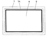
図面に基づき本発明の実施形態を詳述する。図1は本発明の加熱調理器1の要部縦断面図、図2は同図1の加熱調理器1の要部(点線丸印内)の拡大図、図3は本発明の加熱室3底面7の平面図をそれぞれ示している。
Embodiments of the present invention will be described in detail with reference to the drawings. 1 is a longitudinal sectional view of a main part of the
図1において、1は食品にマイクロ波を当てて加熱する加熱調理器、2は加熱調理器1の本体、3は本体2内に設けられ食品を加熱調理するための加熱室で、本体2の前面となる加熱室3の横には調理者が調理情報を入力するためのタイマなどの操作スイッチが備えられた操作パネル(図示せず)が設けられている。本体2には脚2Aが複数設けられており、これらの脚2Aは本体2を下方から4隅で支持する。
In FIG. 1, 1 is a heating cooker that heats food by applying microwaves, 2 is a main body of the
該加熱室3は、両側面を仕切る側壁4、4と、後面を覆う後壁5と、上面を覆う天壁6と、下面を覆い所定の形状に折曲された底面7とから前面を開口する箱状に形成されている。これら側壁4、4、後壁5、天壁6及び底面7は金属板が屈曲されて箱状に形成されている。加熱室3の前面開口は図示しないドアにて開閉可能に閉塞されている。本体2内となる加熱室3の下方には加熱室3内に収納した食品に均一にマイクロ波を当てるための回転アンテナ11が設けられており、この回転アンテナ11は後述するマグネトロン14から発振するマイクロ波を加熱室3内に拡散させる。加熱室3の両側壁4、4には載置棚4Aが複数段設けられており、これらの載置棚4Aによって多数の食品を加熱調理できるように構成されている。
The
回転アンテナ11と加熱室3の間にはセラミック等の非誘電部材からなる底板8が設けられており、この底板8は加熱室3と回転アンテナ11が存在する領域とを仕切っている。該底板8は回転アンテナ11の上方に配置されて加熱室3の底面7を平面に構成すると共に、底板8は加熱室3底面7の全体より僅か小さな大きさを呈している。尚、底面7の底板8に対応する部分を下方に折曲し所定寸法突出させて回転アンテナ11を設置する空間(領域)を形成している。
A
本体2内部の加熱室3の下部には導波管13が左右方向に延在して設けられており、この導波管13の右側端部上側となる加熱室3の側壁4側部にマグネトロン14が設けられている。マグネトロン14には図示しないがマグネトロン14から発振されたマイクロ波を導波管13内に放出するマグネトロンアンテナを備えており、マグネトロン14(マグネトロンアンテナを含む)は回転アンテナ11が存在する領域を介して加熱室3内に連通している。回転アンテナ11の下方には回転アンテナ11を回転させるためのモータ12が回転軸12Aを介して接続され、回転アンテナ11は、このモータ12によって回転する。
A
そして、マグネトロン14から発振されたマイクロ波は導波管13内を経てモータ12の駆動により回転する回転アンテナ11で拡散され加熱室3内全体にまんべんなく放出される。また、側壁4上部には図示しないマイクロ波放出口が設けられており、このマイクロ波放出口からもマグネトロン14から発振されたマイクロ波が加熱室3内に放出される。これによって加熱室3内の調理皿15に載置された食品は下方と上方からまんべんなく加熱され好適に調理される。尚、回転アンテナ11にて加熱室3内にまんべんなくマイクロ波を放出する技術については従来より周知の技術であるため詳細な説明を省略する。
Then, the microwave oscillated from the
一方、前記底板8は加熱室3の底面7とシリコン等の接着剤9にて接着固定されている。この底板8は加熱室3底面7に全周縁部が接着剤9で固定されるが、接着剤9はどうしても底板8より僅か盛り上ってしまう。そこで、本発明では底板8の外径外側となる加熱室3底面7を天壁6方向に所定寸法突出させた突部7Aを設けている(図2)。この突部7Aはプレス(図示せず)により底板8の外径外側に所定の幅で突出させると共に、突部7Aは底板8と加熱室3の底面7を接着している接着剤9より僅か高い距離天壁6方向に突出させている(図3)。以降突部7Aはプレスにて突出されているものとする。
On the other hand, the
即ち、突部7Aは加熱室3の底面7に調理皿15を載置した際調理皿15が接着剤9に接触しない高さに構成している。尚、突部7Aの高さは接着剤9と略同等(僅か接触する高さ)でも差し支えない。これにより、加熱室3内へ調理皿15を挿入する際底板8を固定している接着剤9が調理皿15の挿入で剥がれてしまうなどの不都合を確実に防止することができる。また、底板8を加熱室3底面7に接着している接着剤9が剥がれないので加熱室3内への調理皿15の挿脱を円滑に行うことができる。
That is, the
このように、接着剤9の高さより高い突部7Aを底板8の外形外側周囲に沿って全周に設けているので、載置棚4Aを使用せずに加熱室3の底面7に直接調理皿15を載置して使用する際は、底面7を接着剤9に接触させることなく突部7Aに調理皿15を接触させた状態で調理皿15をセットすることができる。これにより、底板8を固定している接着剤9に調理皿15を接触させずに浮かせることができるので、調理皿15の挿入性や脱出性などの摺動性を大幅に向上させることができる。また、接着剤9より調理皿15を浮かした状態で挿脱させることができるので、調理皿15が接触して接着剤9が剥がれてしまう等の不都合を確実に回避することができる。
In this way, the
特に、突部7Aは底面7を、プレスを用いて突出させているだけなので、底面7折曲用のプレス機の金型に一体に突出型を設けておけば、格別な突出型を使用することなく底面7に突部7Aを突出させることができる。これにより、突部7Aの高さの寸法を極めて安定させることができ、調理皿15を安定した状態で挿脱することが可能となる。また、格別な突出型を使用することなく底面7に突部7Aを突出させることができるので、底面7のコストの高騰も阻止することができる。
In particular, since the
他方、図4に他の底面7(突部7A)を示している。この場合、底面7両側に前述同様の突部7Aを断続的に設けている。この場合突部7Aは、加熱室3の前面開口側から所定寸法後壁5側に延在させると共に、後壁5側から所定寸法前面開口側に延在させている。即ち、加熱室3の前面開口側から後壁5方向に延在する突部7Aの中間を削除して加熱室3の前面開口側と後壁5側の2箇所に断続的に設けている。具体的には、底板8の外形外側周囲に沿って全周に設けた前述の突部7Aを、底面7両側の前後2箇所(両側4箇所)だけに配置した構成としている。これにより、調理皿15と突部7Aとの接触面積を小さくすることができるので、調理皿15を安定した状態で円滑に挿脱することが可能となる。また、前述同様の効果を得ることができる。
On the other hand, FIG. 4 shows another bottom surface 7 (
また、図5に他の底面7(突部7A)を示している。この場合、底面7両側に前述同様の突部7Aを設けている。この突部7Aは、加熱室3の前面開口側から後壁5側まで延在させている。即ち、底板8の外形外側周囲に沿って全周に設けた前述の突部7Aを、底面7両側にそれぞれ配置した構成としている。これにより、図4の底面7前後の2箇所に配置した突部7Aに対して調理皿15と突部7Aとの接触面積が大きくなるので、調理皿15に図示しない重い食料や容器などを載置した場合でも、安定した状態で調理皿15を円滑に挿脱することが可能となる。また、前述同様の効果を得ることができる。
FIG. 5 shows another bottom surface 7 (
実施の形態2.
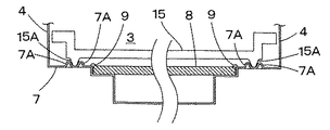
図6は本発明の他の一実施形態の加熱調理器1(要部)の縦断面図である。尚、前述の実施の形態と同じ部分にはこれと同じ符号を付し、説明を省略する。前述の実施の形態で説明したような加熱調理器1において、底面7両側に図5同様に突部7Aを設けると共に、調理皿15の下面両側に底面7方向に所定寸法突出する突部15Aを設けている。この突部15Aは調理皿15が高周波透過性のセラミックにて形成されているので、調理皿15の成形段階で底面7方向に所定寸法突出させて成形することができる。本実施形態では突部15Aは、加熱室3の前面開口側から後壁5側に渡って平行に設けられていて、該突部15Aは底面7に設けた突部7Aと略同等に構成している。
Embodiment 2. FIG.
FIG. 6 is a longitudinal sectional view of a cooking device 1 (main part) of another embodiment of the present invention. The same parts as those in the above-described embodiment are denoted by the same reference numerals, and description thereof is omitted. In the
また、突部15Aは底板8と加熱室3の底面7を接着している接着剤9より所定寸法側壁4側に離間させると共に、側壁4より接着剤9側に所定寸法離間させている。即ち、調理皿15の下面両側に平行に設けた突部15A、15Aを接着剤9と側壁4との間に設けている。また、底面7両側に設けた突部7Aは突部15A同様平行に設けると共に、両突部7A、7Aは両突部15A、15Aの側壁4側に設けている。この両突部7A、7Aも、突部15A、15A同様接着剤9と側壁4との間に位置して設けている(図7)。この場合、調理皿15の下面両側に設けた突部15A、15Aを両突部7A、7Aの内側に配置している。
Further, the
該側壁4側の突部7Aと接着剤9側の突部15Aとは僅か間隔を存して配置され、例えば調理皿15が左側に寄った場合は、右側の突部7Aに突部15Aが当接(この場合、左側の突部7Aと突部15Aとの隙間は大きくなる)して、調理皿15がそれ以上側壁4側に移動しないように規制している。また、調理皿15が右側に寄った場合は、左側の突部7Aに突部15Aが当接(この場合、右側の突部7Aと突部15Aとの隙間は大きくなる)して、調理皿15がそれ以上側壁4側に移動しないように規制している。
The
このように、底面7両側に突部7A、7Aを設けると共に、この突部7A、7Aの間に入るように調理皿15に突部15A、15Aを設けているので、調理皿15が左右どちら側に寄った場合でも、調理皿15が加熱室3の側壁4方向へ移動してしまうのを規制することができる。これにより、調理皿15の縁が側壁4に当たって側壁4に傷付いてしまうのを防止することができる。また、調理皿15の縁が側壁4に当たらないので、調理皿15を円滑に挿脱することができる。尚、実施の形態では両突部7A、7Aの内側に調理皿15の下面両側に設けた突部15A、15Aを配置したが、調理皿15の下面両側に設けた突部15A、15Aを両突部7A、7Aの外側に配置しても同様の効果を得ることができる。
As described above, the
実施の形態3.
図8は本発明の他の一実施形態の加熱調理器1(要部)の縦断面図である。尚、前述の各実施の形態と同じ部分にはこれと同じ符号を付し、説明を省略する。前述の実施の形態で説明したような加熱調理器1において、実施の形態2の加熱室3の底面7一側(加熱室3の左側)に2列の突部7A、7Aを設けている。この場合、実施の形態2の右側の突部7Aは設けていない。即ち、実施の形態2の底面7左側に設けた突部7Aと、この突部7Aと所定の間隔を存して接着剤9側に突部7Aを設けている。この両突部7A、7Aを平行に設けると共に、両突部7A、7Aは調理皿15の下面両側に設けた一方の突部15Aを挿入可能な間隔で配置している。即ち、調理皿15が前後どちらの方向から加熱室3内に挿入された場合でも、調理皿15の一方の突部15Aが両突部7A、7A間に挿入できるように構成している。
FIG. 8 is a longitudinal sectional view of a heating cooker 1 (main part) according to another embodiment of the present invention. The same parts as those in the above-described embodiments are denoted by the same reference numerals, and description thereof is omitted. In the
このように、加熱室3の一側(左側)に平行に突部7A、7Aを設けると共に、この突部7A、7Aの間に入るような位置に調理皿15に突部15A、15Aを設けているので、調理皿15が左右どちら側に寄った場合でも加熱室3の側壁4方向へ移動するのを規制することができる。これにより、調理皿15の縁が側壁4に当たって側壁4に傷付いてしまうのを防止することができる。また、調理皿15の縁が側壁4に当たらないので、調理皿15を円滑に挿脱することができる。尚、実施の形態では両突部7A、7Aを加熱室3の一側(左側)に設けているが、両突部7A、7Aを加熱室3の他側(右側)に設けても同様の効果を得ることができる。また、調理皿15に両突部7A、7A同様突部15Aを2列設け、底面7の突部7Aを調理皿15に設けた2列の突部15A、15A間に挿入して、調理皿15が加熱室3の側壁4方向へ移動するのを規制しても同様の効果を得ることができる。
As described above, the
実施の形態4.
図9は本発明の他の一実施形態の加熱調理器1(要部)の縦断面図である。尚、前述の各実施の形態と同じ部分にはこれと同じ符号を付し、説明を省略する。前述の実施の形態で説明したような加熱調理器1において、実施の形態3の加熱室3の一側に設けた2列の突部7A、7Aを加熱室3の両側に設けている。即ち、加熱室3の両側に設けた突部7A、7A間と突部7A、7A間には調理皿15の下面両側に設けた両突部15A、15Aを挿入可能な間隔で配置している。これにより、調理皿15が前後どちらの方向から加熱室3内に挿入された場合でも、調理皿15の両方の突部15A、15Aが加熱室3の両側に設けた両突部7A、7A間に挿入できるように構成している。
FIG. 9 is a longitudinal sectional view of a heating cooker 1 (main part) according to another embodiment of the present invention. The same parts as those in the above-described embodiments are denoted by the same reference numerals, and description thereof is omitted. In the
このように、加熱室3の両側にそれぞれ平行に突部7A、7Aを設けると共に、この突部7A、7Aの間に入るような位置に調理皿15に突部15A、15Aを設けているので、調理皿15が左右どちら側に寄った場合でも、調理皿15が加熱室3の側壁4方向へ移動してしまうのを両側の突部7A、7Aでより安定して規制することができる。これにより、調理皿15の縁が側壁4に当たって側壁4に傷が付いてしまうのを防止することができる。また、調理皿15の縁が側壁4に当たらないので、調理皿15を円滑に挿脱することができる。尚、実施の形態では両突部7A、7Aを加熱室3の底面7両側に設けると共に、調理皿15の下面両側に底面7両側に設けた両突部7A、7A間に入る突部15Aを設けているが、調理皿15の下面両側に底面7両側に設けた両突部7A、7A同様突部15Aをそれぞれ2列平行に設けると共に、調理皿15の下面両側に設けた2列の突部15A、15A間に入る突部7Aを底面7両側に設けても同様の効果を得ることができる。
As described above, the
実施の形態5.
図10は本発明の他の一実施形態の加熱調理器1(要部)の縦断面図である。尚、前述の各実施の形態と同じ部分にはこれと同じ符号を付し、説明を省略する。前述の実施の形態で説明したような加熱調理器1において、調理皿15の下面両側壁4、4側に突部15Aを設けている。該調理皿15には実施の形態2の如き突部15Aを、調理皿15の両側(一側図示せず)に設けている。尚、底面7には突部7Aを設けていない。即ち、調理皿15の両側に下方に突出する突部15Aを設けて、底板8を加熱室3底面7に接着している接着剤9の高さより調理皿15を浮かせている。
FIG. 10 is a longitudinal sectional view of a heating cooker 1 (main part) according to another embodiment of the present invention. The same parts as those in the above-described embodiments are denoted by the same reference numerals, and description thereof is omitted. In the
これにより、加熱調理器1の加熱室3底面7に突部7Aを加工しなくても、底面7を加熱室3底面7に接着している接着剤9より調理皿15を浮かせることができる。また、底面7に突部7Aを形成していないので、当該底面7の清掃作業を容易に行うことができて、加熱室3内底面7の清掃作業性を大幅に向上することができるようになる。
Thereby, even if it does not process 7 A of protrusions in the
1 加熱調理器、2 本体、2A 脚、3 加熱室、4 側壁、4A 載置棚、5 後壁、6 天壁、7 底面、7A 突部、8 底板、9 接着剤、11 回転アンテナ、12 モータ、12A 回転軸、13 導波管、14 マグネトロン、15 調理皿、15A 突部。
DESCRIPTION OF
Claims (5)
前記加熱室内の食品を加熱するためのマグネトロンと、
前記加熱室の下方に回転可能に設けられ、前記マグネトロンが発振したマイクロ波を前記加熱室内に供給するための回転アンテナと、
前記加熱室の底面より小さい幅を有し、前記底面の前記加熱室側壁より離れた位置に前記加熱室と前記回転アンテナが存在する領域とを仕切るように接着固定された底板と、
前記底板を接着固定する接着剤により前記底板より高く形成された盛り上がり部と、
前記底板よりも大きな幅を有し、その両端が前記加熱室に収納された際に前記底板の両端より前記加熱室側壁側に配置される、食品を載置する調理皿とを備え、
前記加熱室の底面に、前記調理皿を前記底板から所定寸法離間させるための突部を前記盛り上がり部の高さと略同じ、或いは、それよりも僅かに高い高さで、前記調理皿が前記盛り上がり部に接触しないか僅かに接触する高さに設け、
前記調理皿は前記突部と接触させた状態で前記加熱室に挿脱可能で、且つ、前記突部に載置して調理可能に構成されたことを特徴とする加熱調理器。 A heating chamber for storing food,
A magnetron for heating the food product of the heating chamber,
A rotating antenna that is rotatably provided below the heating chamber and that supplies microwaves oscillated by the magnetron into the heating chamber;
A bottom plate having a width smaller than the bottom surface of the heating chamber and bonded and fixed so as to partition the heating chamber and the region where the rotating antenna exists at a position away from the heating chamber side wall of the bottom surface ;
A raised portion formed higher than the bottom plate by an adhesive that bonds and fixes the bottom plate;
A cooking pan on which food is placed, having a larger width than the bottom plate, and arranged on both sides of the heating chamber from both ends of the bottom plate when both ends thereof are housed in the heating chamber ;
The bottom surface of the heating chamber, before Symbol cooking dish the bottom plate from the predetermined size height and stands for the projections for spacing the raised part same, or slightly higher in height than, the cooking dish is the Set at a height that does not touch or slightly touches the raised part,
The cooking device according to claim 1, wherein the cooking dish is configured to be inserted into and removed from the heating chamber in a state of being in contact with the protrusion and to be cooked by being placed on the protrusion .
前記加熱室内の食品を加熱するためのマグネトロンと、
前記加熱室の下方に回転可能に設けられ、前記マグネトロンが発振したマイクロ波を前記加熱室内に供給するための回転アンテナと、
前記加熱室の底面より小さい幅を有し、前記底面の前記加熱室側壁より離れた位置に前記加熱室と前記回転アンテナが存在する領域とを仕切るように接着固定された底板と、
前記底板を接着固定する接着剤により前記底板より高く形成された盛り上がり部と、
前記底板よりも大きな幅を有し、その両端が前記加熱室に収納された際に前記底板の両端より前記加熱室側壁側に配置される、食品を載置する調理皿とを備え、
前記底板から所定寸法離間させるための突部を前記盛り上がり部の高さと略同じ、或いは、それよりも僅かに高い高さで、前記調理皿が前記盛り上がり部に接触しないか僅かに接触する高さに、前記盛り上がり部と加熱室側壁との間に位置するように前記調理皿の左右両側に設け、
前記調理皿は前記突部を前記底面と接触させた状態で前記加熱室に挿脱可能で、且つ前記底面に載置して調理可能に構成されたことを特徴とする加熱調理器。 A heating chamber for storing food,
A magnetron for heating the food product of the heating chamber,
A rotating antenna that is rotatably provided below the heating chamber and that supplies microwaves oscillated by the magnetron into the heating chamber;
A bottom plate having a width smaller than the bottom surface of the heating chamber and bonded and fixed so as to partition the heating chamber and the region where the rotating antenna exists at a position away from the heating chamber side wall of the bottom surface ;
A raised portion formed higher than the bottom plate by an adhesive that bonds and fixes the bottom plate;
A cooking pan on which food is placed, having a larger width than the bottom plate, and arranged on both sides of the heating chamber from both ends of the bottom plate when both ends thereof are housed in the heating chamber ;
Before Symbol height substantially of the projections for the bottom plate by a predetermined dimension away the raised part the same, or slightly at a higher level than the high of the cooking dish is slightly contacted or not contacted with the protruding portion In addition , provided on the left and right sides of the cooking dish so as to be located between the raised portion and the side wall of the heating chamber ,
The cooking device according to claim 1, wherein the cooking dish is configured to be able to be inserted into and removed from the heating chamber in a state in which the protrusion is in contact with the bottom surface, and to be cooked by being placed on the bottom surface .
Priority Applications (1)
| Application Number | Priority Date | Filing Date | Title |
|---|---|---|---|
| JP2003312563A JP3731824B2 (en) | 2003-09-04 | 2003-09-04 | Cooker |
Applications Claiming Priority (1)
| Application Number | Priority Date | Filing Date | Title |
|---|---|---|---|
| JP2003312563A JP3731824B2 (en) | 2003-09-04 | 2003-09-04 | Cooker |
Publications (3)
| Publication Number | Publication Date |
|---|---|
| JP2005083586A JP2005083586A (en) | 2005-03-31 |
| JP2005083586A5 JP2005083586A5 (en) | 2005-09-02 |
| JP3731824B2 true JP3731824B2 (en) | 2006-01-05 |
Family
ID=34413783
Family Applications (1)
| Application Number | Title | Priority Date | Filing Date |
|---|---|---|---|
| JP2003312563A Expired - Lifetime JP3731824B2 (en) | 2003-09-04 | 2003-09-04 | Cooker |
Country Status (1)
| Country | Link |
|---|---|
| JP (1) | JP3731824B2 (en) |
Families Citing this family (3)
| Publication number | Priority date | Publication date | Assignee | Title |
|---|---|---|---|---|
| JP2007101062A (en) * | 2005-10-04 | 2007-04-19 | Mitsubishi Electric Corp | Heating cooking device |
| JP4964175B2 (en) * | 2008-03-10 | 2012-06-27 | 三菱電機株式会社 | Cooker |
| CN106051842B (en) * | 2016-06-14 | 2018-02-16 | 广东美的厨房电器制造有限公司 | Micro-wave oven |
-
2003
- 2003-09-04 JP JP2003312563A patent/JP3731824B2/en not_active Expired - Lifetime
Also Published As
| Publication number | Publication date |
|---|---|
| JP2005083586A (en) | 2005-03-31 |
Similar Documents
| Publication | Publication Date | Title |
|---|---|---|
| JP3731824B2 (en) | Cooker | |
| US4208561A (en) | Microwave oven shelf with embedded grille | |
| JP2007101062A (en) | Heating cooking device | |
| KR101157617B1 (en) | Microwave oven of cooking room capacity variable type | |
| JP2005083586A5 (en) | ||
| US7059253B2 (en) | Table and microwave oven provided with table | |
| JP2864893B2 (en) | High frequency heating equipment | |
| JP4964175B2 (en) | Cooker | |
| JP2005257216A (en) | Microwave oven | |
| JP2007101122A (en) | Heating cooker | |
| JP2000130770A (en) | Cooking tray and cooking appliance | |
| US6759638B2 (en) | Microwave oven having a projecting door and cooking cavity | |
| JP2004333048A (en) | Heating cooker | |
| JP2012042080A (en) | Heating cooker | |
| JP4262519B2 (en) | Cooker | |
| KR100270867B1 (en) | Cooking aux-tool for microwaveoven | |
| KR20000012565U (en) | microwave | |
| JPH0674465A (en) | Heater using high frequency wave | |
| JP3941051B2 (en) | Cooker | |
| KR19990009702U (en) | Microwave Cooking Support Member | |
| KR200193963Y1 (en) | Cabinet assembly of a microwaveoven | |
| KR100813720B1 (en) | Control unit of oven | |
| JPH06337119A (en) | Microwave heating device with heater | |
| JP2004353950A (en) | Heating cooker | |
| JP2004347217A (en) | Heating cooker |
Legal Events
| Date | Code | Title | Description |
|---|---|---|---|
| A521 | Request for written amendment filed |
Free format text: JAPANESE INTERMEDIATE CODE: A523 Effective date: 20050428 |
|
| A621 | Written request for application examination |
Free format text: JAPANESE INTERMEDIATE CODE: A621 Effective date: 20050428 |
|
| A871 | Explanation of circumstances concerning accelerated examination |
Free format text: JAPANESE INTERMEDIATE CODE: A871 Effective date: 20050428 |
|
| A975 | Report on accelerated examination |
Free format text: JAPANESE INTERMEDIATE CODE: A971005 Effective date: 20050623 |
|
| A131 | Notification of reasons for refusal |
Free format text: JAPANESE INTERMEDIATE CODE: A131 Effective date: 20050628 |
|
| A521 | Request for written amendment filed |
Free format text: JAPANESE INTERMEDIATE CODE: A523 Effective date: 20050826 |
|
| TRDD | Decision of grant or rejection written | ||
| A01 | Written decision to grant a patent or to grant a registration (utility model) |
Free format text: JAPANESE INTERMEDIATE CODE: A01 Effective date: 20050920 |
|
| A61 | First payment of annual fees (during grant procedure) |
Free format text: JAPANESE INTERMEDIATE CODE: A61 Effective date: 20051006 |
|
| R150 | Certificate of patent or registration of utility model |
Ref document number: 3731824 Country of ref document: JP Free format text: JAPANESE INTERMEDIATE CODE: R150 Free format text: JAPANESE INTERMEDIATE CODE: R150 |
|
| FPAY | Renewal fee payment (event date is renewal date of database) |
Free format text: PAYMENT UNTIL: 20091021 Year of fee payment: 4 |
|
| FPAY | Renewal fee payment (event date is renewal date of database) |
Free format text: PAYMENT UNTIL: 20091021 Year of fee payment: 4 |
|
| FPAY | Renewal fee payment (event date is renewal date of database) |
Free format text: PAYMENT UNTIL: 20101021 Year of fee payment: 5 |
|
| FPAY | Renewal fee payment (event date is renewal date of database) |
Free format text: PAYMENT UNTIL: 20111021 Year of fee payment: 6 |
|
| FPAY | Renewal fee payment (event date is renewal date of database) |
Free format text: PAYMENT UNTIL: 20121021 Year of fee payment: 7 |
|
| FPAY | Renewal fee payment (event date is renewal date of database) |
Free format text: PAYMENT UNTIL: 20131021 Year of fee payment: 8 |
|
| R250 | Receipt of annual fees |
Free format text: JAPANESE INTERMEDIATE CODE: R250 |
|
| R250 | Receipt of annual fees |
Free format text: JAPANESE INTERMEDIATE CODE: R250 |
|
| R250 | Receipt of annual fees |
Free format text: JAPANESE INTERMEDIATE CODE: R250 |
|
| R250 | Receipt of annual fees |
Free format text: JAPANESE INTERMEDIATE CODE: R250 |
|
| R250 | Receipt of annual fees |
Free format text: JAPANESE INTERMEDIATE CODE: R250 |
|
| R250 | Receipt of annual fees |
Free format text: JAPANESE INTERMEDIATE CODE: R250 |
|
| R250 | Receipt of annual fees |
Free format text: JAPANESE INTERMEDIATE CODE: R250 |
|
| R250 | Receipt of annual fees |
Free format text: JAPANESE INTERMEDIATE CODE: R250 |
|
| EXPY | Cancellation because of completion of term |