JP3731449B2 - Communication terminal device - Google Patents
Communication terminal device Download PDFInfo
- Publication number
- JP3731449B2 JP3731449B2 JP2000186184A JP2000186184A JP3731449B2 JP 3731449 B2 JP3731449 B2 JP 3731449B2 JP 2000186184 A JP2000186184 A JP 2000186184A JP 2000186184 A JP2000186184 A JP 2000186184A JP 3731449 B2 JP3731449 B2 JP 3731449B2
- Authority
- JP
- Japan
- Prior art keywords
- call
- transfer
- caller
- communication
- communication terminal
- Prior art date
- Legal status (The legal status is an assumption and is not a legal conclusion. Google has not performed a legal analysis and makes no representation as to the accuracy of the status listed.)
- Expired - Fee Related
Links
Images


Landscapes
- Telephonic Communication Services (AREA)
- Telephone Function (AREA)
Description
【0001】
【発明の属する技術分野】
本発明は、回線業者がサ−ビスする通話の応答後転送モ−ドと、通信中着信機能(キャッチホン機能)が並立して設定されている場合に、両者の機能が円滑に実現できる構成とした通信端末装置に関する。
【0002】
【従来の技術】
ファクシミリ装置においては、コピ−機能を併せ持つ複合機として構成されるものが知られている。このような複合機は、一般にオ−トドキュメントフィ−ダ(ADF)や、フラットベッドスキャナ(FBS)として機能するフラットベッド型の読み取り用原稿載置台が備え付けられている。
【0003】
複合機で原稿をコピ−する際には、コピ−部数や原稿の種類(通常の文字や図形のイメ−ジ情報か写真か)に応じた読み取りモ−ド(解像度)を指定してから、スタ−トボタンを押して原稿の読み取りを開始し、指定した部数の記録紙にコピ−プリントしている。
【0004】
前記複合機等の通信端末装置においては、通話機能を有するものや、発信元から送信される画像を受信して、受信した画像を予め設定されている転送先に転送する機能を有するものが知られている。
【0005】
画像を転送する場合には、発信元から送信された画像を交換機を通して通信端末装置が受信して画像メモリに記憶する。通信端末装置は転送元となって、受信した画像を必要に応じて交換機を通して転送先に転送する。
【0006】
また、通話機能を有する通信端末装置においては、回線業者がサ−ビスする転送機能を用いて、通信端末装置で着信した発信元からの通話を転送先に転送する構成とすることができる。通信端末装置は、異なる時間に着信した通話をそれぞれ指定された転送先に順次転送する。
【0007】
このような通話転送の一形態として、応答後転送モ−ドが知られている。応答後転送モ−ドは、転送元で一旦通話に応答してから転送先に転送するものである。通話の応答後転送の機能を用いる際には、転送元である通信端末装置で自動転送有りの設定をする。
【0008】
また、回線業者からは、通話中に他の通話を割込ませる通信中着信機能(キャッチホン)のサ−ビスが提供されている。このキャッチホンには、割込み通話を録音するキャッチホンIIのサ−ビスも提供されている。このように、通信端末装置には、回線業者がサ−ビスする通話の応答後転送モ−ドと、キャッチホンの機能が並立して設定されている場合がある。
【0009】
前記のような応答後転送を自動的に行なう通信端末装置においては、着呼後に、フックスイッチまたはフックボタンを押してフッキングすることによりオフフック(応答信号)を交換機に送出して、一時的に通話状態を形成する。交換機は、この応答信号を受信すると発信元からの通話を転送先に転送する。
【0010】
また、キャッチホンの契約をしている通信端末装置においては、通話中に呼び出し信号(通信中着信表示音:IIT)を受信すると、フックスイッチまたはフックボタンを押してフッキングすることによりオフフック(応答信号)を交換機に送出して、割込み発呼者と通話する。
【0011】
【発明が解決しようとする課題】
このように、通信端末装置に回線業者がサ−ビスする通話の応答後転送モ−ドと、通信中着信機能(キャッチホン)が並立して設定されている場合には、いずれの機能も通信状態のときにフッキングすることが必要となる。
【0012】
しかしながら、通信状態のときにフッキングされると、キャッチホンの機能が優先して作動する。このため、通話の応答後転送ができない状態となるが、利用者は応答後転送ができない理由が分からないので対応に手間取るという問題があった。
【0013】
また、通話の応答後転送モ−ドで動作中にキャッチホンの割込み信号があると、前記IIT信号が通信端末装置に送出される。しかしながら、通信端末装置の利用者は電話機を置いた状態(オンフック)であるので、このITT信号を聞き取ることができず、割込み発呼者と通話をすることができないという問題があった。
【0014】
本発明は、かかる現状に鑑みてなされたものであり、回線業者がサ−ビスする通話の応答後転送モ−ドと、通信中着信機能(キャッチホン機能)が並立して設定されている場合に、両者の機能が円滑に実現できる通信端末装置の提供を目的とする。
【0015】
【課題を解決するための手段】
上記目的は、請求項1に係る発明において、通信端末装置を、第1発信元、第2発信元、転送先とそれぞれ交換機を介して接続され、前記第1発信元との応答後に前記第1発信元の通話を転送先へ転送する応答後転送機能および前記第1発信元と通話中に前記第2発信元の通話を割り込ませる通信中着信機能が設定される通信端末装置であって、前記第1発信元と通話中に前記第2発信元の通話を割り込ませるときに前記交換機から送出される通信中着信表示音を検出する通信中着信表示音検出手段を設けるとともに、前記通信中着信表示音検出中前記第1発信元の通話を転送先へ転送することができないことを報知する手段を設けた構成とすることによって達成することができる。
【0016】
また、請求項2に係る発明は、前記通信中着信表示音を検出すると応答後転送を中断し、前記通信中着信表示音が終了すると前記応答後転送を再開する手段を設けたことを特徴としている。
【0017】
また、請求項3に係る発明は、請求項1または請求項2に記載の通信端末装置において、前記第1発信元との通信中に、通信中着信表示音を検出したときに鳴動する疑似ベルを設けたことを特徴としている。
【0018】
請求項1に係る発明の上記特徴によれば、応答後転送で第1発信元との通信中に第2発信元からの着信があるときに、交換機から送出される通信中着信表示音(IIT信号)を検出する手段と、前記IIT信号検出中は応答後転送はできないことを報知する手段とを設けている。このため、利用者は応答後転送ができない理由を認識することができる。
【0019】
請求項2に係る発明によれば、前記IIT信号を検出すると応答後転送を中断し、IIT信号が終了すると応答後転送を再開する手段を設けている。このため、通信中着信機能が設定されている場合でも応答後転送を支障なく実行することができる。
【0020】
請求項3に係る発明によれば、第1発信元との通信中に、IIT信号を検出したときに鳴動する疑似ベルを設けている。このため、利用者は通信中着信(キャッチホン)があったことを認識して、割込み通話に対応することができる。
【0021】
【発明の実施の形態】
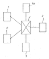
以下、本発明の実施の形態について図面を参照して説明する。図1は、通話機能を有する通信端末装置を配置した例を示すブロック図である。図1において、1は発信元(第1発信元)、1aは割込み発呼者(第2発信元)、2は交換機、3は転送元の通信端末装置、4、5は転送先である。
【0022】
このような通信端末装置3において、回線業者がサ−ビスする応答後転送機能が設定されるものとする。この場合には、発信元1からの通話があるときに、交換機2は転送元である通信端末装置3の電話を呼び出して、通信端末装置3で応答すると交換機2が転送先4、5にこの通話を転送する。
【0023】
また、通信中着信機能(キャッチホン機能)が通信端末装置3に設定されているものとすると、発信元1(第1発信元)と通話中に、割込み発呼者1a(第2発信元)からの発呼信号があると、交換機2からは通信端末装置3に対してIIT信号(通信中着信表示音)が送出される。
【0024】
本発明においては、通信端末装置3に通話の応答後転送機能と、キャッチホン機能が並立して設定されている場合に、着信後キャッチホンの割込み信号により交換機からIIT信号が到来すると、通信端末装置にIIT信号検出中は応答後転送はできない旨を報知する手段を設けている。
【0025】
また、応答後転送モ−ドで動作中にIIT信号を検出すると応答後転送を中断し、IIT信号の終了後に応答後転送を再開している。さらに、応答後転送モ−ドで動作中にIIT信号を検出すると、疑似ベルを鳴動して利用者に割込み通話がある旨を報知している。
【0026】
図2は本発明の通信端末装置の制御装置を示す概略のブロック図である。次にこのブロック図について説明する。図2において、通信端末装置の制御装置11は、各種信号やデ−タを処理するための制御部12を有している。この制御部12は、例えばCPU(中央処理装置)により構成されている。
【0027】
制御部12には、回線制御部(NCU)14、モデム15、画像メモリ16、RAM17、ROM18、表示部19、操作部20、読取部21、記録部22、音声圧縮メモリ23、音声コ−デック26、フックスイッチ27、画像コ−デック28、ブザ−29が接続されている。
【0028】
回線制御部14は、図示を省略している交換機を介して外部回線13と接続され、相手先のダイヤル番号に対応したダイヤルパルスの送出、及び着信を検出する。VFモデム15は、ITU(国際通信連合)のT.svf(音声ファクシミリ同時通信端末)勧告に基づいて構成されており、画像と音声の通信を可能としている。なお、SVFモデム15に代えて音声機能付のモデムを使用することもできる。
【0029】
画像メモリ16は、前記回線制御部14とSVFモデム15からなる通信部により送受信される画像を格納する。RAM17は予約送信またはメモリ受信における管理デ−タが格納される。また、転送先の電話番号を予め設定しておく転送テ−ブルが格納される。ROM18には通信端末装置の各種動作に必要なデ−タやプログラムが格納される。
【0030】
陰極線管(CRT)や液晶表示器(LCD)を用いた表示部19には、通信端末装置の動作に必要な各種メッセ−ジが表示される。キ−ボ−ドやマウス等からなる操作部20は通信端末装置の各種動作、停止を指示する。また、原稿の画像の拡大倍率を設定する。
【0031】
読取部21は、送信側から送信されてきた原稿の画像を読み取る。両面原稿を読み取る場合は、表面の画像の読み取りと、裏面の画像の読み取りを行なう。記録部22は送信側から送信されてきた画像を記録紙に記録する。画像の記録は、記録紙の両面に行なう場合と記録紙の片面に行なう場合がある。
【0032】
前記記録部22には電子写真方式のプリンタを設け、受信画像や光学読取系で読み取られた画像を、図示しない給紙カセットから供給される定形サイズの記録紙上にコピ−する。なお、プリンタでは各種デ−タを記録紙に記録することができる。音声圧縮メモリ23には、録音した通話の内容が記憶される。
【0033】
また、操作部20には各種キ−が設けられている。例えば、コピ−・ファクシミリ複合機をコピ−モ−ドとファクシミリ通信モ−ドとのいずれの機能を選択するかのコピ−/通信キ−、原稿が文字等のイメ−ジ情報か写真情報かに応じてコピ−の読み取りモ−ド(解像度)を設定する読み取りモ−ドキ−、自動縮小、自動記録紙選択モ−ドを設定するキ−等の各種動作モ−ドを設定するキ−が設けられている。
【0034】
制御部12は画像メモリ16に格納されている画像を読み出し、当該画像を所定の転送先に転送する。また、録音された通話の内容を音声圧縮メモリから23から読み出して所定の転送先に転送したり、録音されたメッセージを音声圧縮メモリから23から読み出して発信元に送信することができる。なお、時計部を設けて現在時刻をカウントし、その出力を用いて受信した原稿にその時点の時刻を印字することも可能である。
【0035】
ハンドセット24は、通信端末装置の通話用補助電話器を構成し、A/D、D/A変換部25を介して、デジタル音声信号を符号化・復合化処理する音声コ−デック26に接続される。フックスイッチ27は、ハンドセット24のオンフック、オフフックを検出する。
【0036】
なお、図2の例では、フックスイッチ27を外部回線13に接続して、外部回線13の電圧を用いてハンドセット24のオンフック、オフフックを検出しているが、ハンドセット24自体を検出する機械式スイッチによってもハンドセット24のオンフック、オフフックを検出することができる。
【0037】
また、図2の例では、ハンドセット24をA/D、D/A変換部25を介して、音声コ−デック26に接続しているが、NCU14から通常の信号線でハンドセット24を接続して、音声信号を外部回線13に送出する構成としてもよい。
【0038】
画像コ−デック28は、読み取り画像を送信相手先装置の復号能力に合わせて符号化(エンコ−ド)する。また、受信画像を復合化(デコ−ド)し、最も圧縮率の高いMMR方式またはJBIG方式で再符号化して画像メモリに格納する。ブザ−29は、呼び出しアラ−ムを鳴動する。
【0039】
通信端末装置からは、通話時に「後程おかけなおし下さい」等の音声ガイダンスを外部回線13に送出する。このような音声ガイダンスは、製造時に予めROM18に格納しておくことができる。また、ユ−ザがハンドセット24からメッセ−ジを吹き込み、音声圧縮メモリ23に登録しても良い。
【0040】
図3は、制御装置11の別の構成を部分的に示すブロック図である。図3の例では、回線制御部14の具体的構成が示されている。図3において、回線制御部14は、第1のスイッチSaと第2のスイッチSbが設けられている。また、着信検出部14a、直流電圧およびベル信号発生部14b、オフフック検出部14cが設けられている。
【0041】
図3において、前記オフフック検出部14cはハンドセット24に流れる電流を検出している。スイッチSbがa接点側に投入されているときには、回線13のから電流を検出する。また、スイッチSbがb接点側に投入されているときには、直流電圧およびベル信号発生部14bからの電流を検出する。なお、前記オフフック検出部14cはハンドセット24自体を検出する機械式スイッチを用いても良い。また、NCU14から通常の信号線でハンドセット24を接続して、音声信号を外部回線13に送出する構成としている。
【0042】
図3の状態で、発信元の発呼信号の着信を着信検出部14aで検出すると、スイッチSaが閉結され、また、直流電圧およびベル信号発生部14bのベルが鳴動する。着信の報知を図2のブザ−29が鳴動する構成としても良い。利用者がハンドセット24を持ち上げるとスイッチSbは接点a側に切り替わり、ハンドセット24は外部回線13と接続されて通話可能となる。
【0043】
この際にオフフック検出部14cは、ハンドセット24のオフフックを検出する。また、スイッチSaが閉結されると画像と音声がSVFモデム15を通して送受信される。次に、通話中にフッキングすることによりスイッチSbが接点b側に切り替わる。
【0044】
図4〜図8は、本発明の処理手順を示すフロ−チャ−トである。次に、このフロ−チャ−トについて説明する。
【0045】
(1)ステップS1で処理プログラムを開始し、ステップS2で着呼有かどうかを判定する。この判定結果がNO(以下、Nと略記する)であれば、ステップS2の処理の待機状態となる。着呼有りとなってステップS2の判定結果がYES(以下、Yと略記する)であれば、続いてステップS3の処理で呼出音(CNG)有りかどうかを判定する。
【0046】
(2)ステップS3の判定結果がYであれば、ステップS4の処理でファクス通信を行い、ステップS38で処理プログラムを終了する。また、ステップS3の判定結果がNであれば、ステップS5の処理に移行して自動転送設定かどうかを判定する。
【0047】
(3)ステップS5の判定結果がYであれば、ステップS6の処理に移行して、図3のスイッチSaが閉じて回線を閉結し電話機を回線から切り離す。すなわち、図3のスイッチSbは接点b側に切り替わる。電話機には、図3の直流電圧/ベル信号発生部14bから直流を供給する。
【0048】
(4)次に、ステップS7の処理で「転送しますのでお待ち下さい」の音声応答メッセ−ジをSVFモデム15を通して発信元に出力する。続いて、ステップS8の処理でキャッチホン割込みのIIT信号(通信中着信表示音)検出かどうかを判定する。この判定結果がYであれば、通話の応答後転送中に割込み通話が到来したことになるので、次にステップS10の処理で呼び出しベル(疑似ベル)を鳴動させて、応答後転送を一時的に中断してキャッチホンの割込み通話があることを報知する。
【0049】
(5)次にステップS11の処理でオフフックかどうかを判定する。この判定結果がNであれば利用者はまだハンドセットを持ち上げていないので、ステップS8の処理に戻り、ステップS8〜ステップS11のル−プ処理を繰り返す。図3の電話機(ハンドセット)24が持ち上げられてスイッチSbが接点a側に切り替りオフフックになると、ステップS11の判定結果がYとなり、ステップS12の処理に移行する。
【0050】
(6)ステップS12の処理では回線を電話機に切り替え、割込み発呼元との通話が可能な状態とする。次にステップS13の処理でオフフックかどうかを判定する。このときの判定結果はYとなり、続いてステップS14の処理でIIT信号検出かどうかを判定する。この判定結果もYであるから、ステップS15の処理に移行する。ステップS13の判定結果がNであれば、通話が終了して電話機が置かれてスイッチSbはb接点側に切り替わっているので、ステップS38で処理プログラムを終了する。
【0051】
(7)ステップS15では”キャッチホンが入っています。フッキングすると割込み発信音に切り替わります。現在転送はできません”のメッセ−ジを表示する。次にステップS16の処理で転送ボタン押し下げかどうかを判定する。この場合には、前記ステップS15で転送はできない状態であることが表示されているので、転送ボタン押し下げの有無(Y/N)に拘らずステップS17の処理に移行する。
【0052】
(8)ステップS17の処理では、フッキングボタン押し下げかどうかを判定する。この判定結果がYであれば、ステップS18の処理に移行して前記ステップS15の処理で説明した転送不可の表示をクリアする。続いてステップS19の処理で割込み発呼者と通話する。ステップS17の判定結果がNであれば、ステップS13の処理に戻りオフフックかどうかを判定する。
【0053】
(9)次にステップS20の処理で再度のフッキングボタン押し下げかどうかを判定する。この判定結果がNであればステップS19の処理に戻り、ステップS19、ステップS20のル−プ処理を繰り返す。割込み発呼者との通話が終了して再度のフッキングボタン押し下げがなされると、ステップS21の処理に移行して元の通話者と通話する。次にステップS13の処理に戻りオフフックかどうかを判定する。
【0054】
(10)前記ステップS5の処理で、応答後転送の自動転送設定でないと判定されると(判定結果N)ステップS9の処理でオフフックかどうかを判定する。この判定結果がNであれば、ステップS2の処理の待機状態となる。ステップS9の判定結果がYであればステップS13の処理に移行してオフフックかどうかを判定する。
【0055】
(11)前記ステップS8の処理において、キャッチホン割込みのIIT信号(通信中着信表示音)が検出されずに判定結果がNになると、次にステップS22の処理でフッキングを送出する。続いてステップS23の処理で記憶部に格納されている転送先電話番号を読み出して送出する。
【0056】
(12)次にステップS24の処理で相手先が応答したかどうかを判定する。この判定結果がYであれば、ステップS25の処理で転送が成功したものとして回線を切断し、ステップS38で処理プログラムを終了する。
【0057】
(13)前記ステップS24の判定結果がNであれば、ステップS26の処理でタイムアップかどうかを判定する。この判定結果がNであればステップS24の処理に戻り、ステップS24、ステップS26のル−プ処理を繰り返す。タイムアップになるとステップS26の判定結果がYとなってこのル−プ処理を抜け、ステップS27の処理に移行してフッキングを行なう。
【0058】
(14)次にステップS28の処理に移行して”転送先も通話中です。後程おかけください”の音声メッセ−ジを発信元に通知する。続いてステップS29の処理で回線を切断してステップS38で処理プログラムを終了する。
【0059】
(15)前記ステップS14の処理において、キャッチホンの割込み信号が終了してIIT信号検出の判定結果がNになると、ステップS30の処理に移行してフッキングボタン押し下げかどうかを判定する。この判定結果がNであれば、次にステップS31の処理で転送先ボタン押し下げかどうかを判定する。この判定結果がYであれば、続いてステップS32の処理でフッキングを送出し、次にステップS33の処理で記憶部に格納されている転送先電話番号を読み出す。続いてステップS36の処理で転送番号を送出する。
【0060】
(16)前記ステップS31の判定結果がNであれば、ステップS13の処理でオフフックかどうかの判定を行なう。また、ステップS30の判定結果がYでフッキングボタン押し下げと判定されると、次にステップS34の処理でフッキングを送出し、次にステップS35の処理で転送先番号を操作入力する。続いて前記ステップS36の処理で転送番号を送出する。
【0061】
このように、応答後転送を中断してキャッチホンの割込み通話を行なった後に、ステップS30、ステップS34、ステップS35、ステップS36の処理で、すなわち、フッキングとダイヤル操作で応答後転送を再開することができる。また、ステップS31、ステップS32、ステップS33、ステップS36の処理でも、フッキングと転送先番号読み出しにより応答後転送を再開することができる。
【0062】
(17)前記ステップS36の処理に続いて、ステップS37の処理でオフフックかどうかの判定を行なう。この判定結果がYのときにはステップS37のル−プ処理を繰り返す。オンフックとなってステップS37の判定結果がNになると、ステップS38で処理プログラムを終了する。
【0063】
このように、本発明においては、通信端末装置に応答後転送が設定されているときに(ステップS5)、通話中にIIT信号を検出すると、転送できないことを利用者に報知するので(ステップS13〜ステップS15)、利用者は応答後自動転送ができないことを認識することができる。
【0064】
また、通信端末装置に応答後転送が設定されているときに(ステップS5)、IIT信号を検出すると、呼び出しベルを鳴動して利用者に割込み通話があることを報知し、電話機を持ち上げてオフフックとなることを検出している(ステップS8、ステップS10、ステップS11)。このため、利用者は割込み発呼者と通話することができる(ステップS19)。
【0065】
【発明の効果】
以上詳細に説明したように、請求項1に係る発明の上記特徴によれば、応答後転送で第1発信元との通信中に第2発信元からの着信があるときに、交換機から送出される通信中着信表示音(IIT信号)を検出する手段と、前記IIT信号検出中は応答後転送はできないことを報知する手段とを設けている。このため、利用者は応答後転送ができない理由を認識することができる。
【0066】
請求項2に係る発明によれば、前記IIT信号を検出すると応答後転送を中断し、IIT信号が終了すると応答後転送を再開する手段を設けている。このため、通信中着信機能が設定されている場合でも応答後転送を支障なく実行することができる。
【0067】
請求項3に係る発明によれば、第1発信元との通信中に、IIT信号を検出したときに鳴動する疑似ベルを設けている。このため、利用者は通信中着信(キャッチホン)があったことを認識して、割込み通話に対応することができる。
【図面の簡単な説明】
【図1】本発明の実施の形態に係る通信端末装置を用いた構成例を示すブロック図である。
【図2】通信端末装置の制御装置の構成を示すブロック図である。
【図3】制御装置の別の構成を部分的に示すブロック図である。
【図4】本発明の処理手順を示すフロ−チャ−トである。
【図5】本発明の処理手順を示すフロ−チャ−トである。
【図6】本発明の処理手順を示すフロ−チャ−トである。
【図7】本発明の処理手順を示すフロ−チャ−トである。
【図8】本発明の処理手順を示すフロ−チャ−トである。
【符号の説明】
1、1a 発信元
2 交換機
3 通信端末装置
4、5 転送先
11 制御装置
12 中央演算制御部(CPU)
13 外部回線
14 回線制御部(NCU)
15 SVFモデム
16 画像メモリ
19 表示部
20 操作部
21 読取部
22 記録部[0001]
BACKGROUND OF THE INVENTION
The present invention has a configuration in which both functions can be smoothly implemented when a transfer mode after answering a call serviced by a circuit provider and an incoming call function during call (call waiting function) are set side by side. The present invention relates to a communication terminal device.
[0002]
[Prior art]
As a facsimile apparatus, one configured as a multifunction machine having a copy function is known. Such a multi-function peripheral is generally equipped with an auto document feeder (ADF) and a flatbed type reading document placing table that functions as a flatbed scanner (FBS).
[0003]
When copying a document with a multi-function peripheral, specify the scanning mode (resolution) according to the number of copies and the type of document (normal character / graphic image information or photo), When the start button is pressed, reading of the original is started, and copy printing is performed on the designated number of recording sheets.
[0004]
Among communication terminal devices such as the above-mentioned multifunction peripherals, those having a call function and those having a function of receiving an image transmitted from a transmission source and transferring the received image to a preset transfer destination are known. It has been.
[0005]
When transferring an image, the communication terminal apparatus receives the image transmitted from the transmission source through the exchange and stores it in the image memory. The communication terminal device becomes a transfer source, and transfers the received image to the transfer destination through an exchange as necessary.
[0006]
Further, a communication terminal device having a call function can be configured to transfer a call from a caller that has arrived at the communication terminal device to a transfer destination using a transfer function serviced by a network operator. The communication terminal device sequentially transfers calls received at different times to designated transfer destinations.
[0007]
As one form of such call transfer, a post-response transfer mode is known. The post-response transfer mode is a mode in which a call is once answered at the transfer source and then transferred to the transfer destination. When using the transfer function after answering a call, the communication terminal device that is the transfer source is set to have automatic transfer.
[0008]
In addition, the service provider provides a call waiting function (catch phone) that interrupts another call during a call. The call waiting service is also provided with call waiting II for recording an interrupted call. As described above, in some cases, the communication terminal device is set in parallel with the transfer mode after answering a call service provided by the network operator and the call waiting function.
[0009]
In a communication terminal apparatus that automatically performs transfer after answering as described above, after an incoming call, an off-hook (response signal) is sent to the exchange by pressing a hook switch or a hook button to be hooked, thereby temporarily calling Form. When receiving the response signal, the exchange transfers the call from the caller to the transfer destination.
[0010]
In addition, when a call signal (calling signal during communication: IIT) is received during a call, a communication terminal device with a call waiting contract makes an off-hook (response signal) by pressing a hook switch or hook button and hooking it. Sent to the switch to talk to the interrupting caller.
[0011]
[Problems to be solved by the invention]
As described above, when the communication terminal device sets the transfer mode after answering a call serviced by the network operator and the incoming call function (call waiting) during communication, both functions are in the communication state. It is necessary to hook at the time.
[0012]
However, if it is hooked in the communication state, the call waiting function is prioritized. For this reason, the call cannot be transferred after answering, but there is a problem that the user does not know the reason why the call cannot be transferred after answering, so that it takes time to deal with it.
[0013]
Further, if there is a call waiting interrupt signal during operation in the transfer mode after answering the call, the IIT signal is sent to the communication terminal apparatus. However, since the user of the communication terminal apparatus is in a state where the telephone is placed (on-hook), there is a problem that the ITT signal cannot be heard and a call cannot be made with the interrupt caller.
[0014]
The present invention has been made in view of such a situation, and when a transfer mode after answering a call serviced by a circuit provider and an incoming call function (catch phone function) are set side by side. An object of the present invention is to provide a communication terminal device that can smoothly realize both functions.
[0015]
[Means for Solving the Problems]
According to the first aspect of the present invention, the communication terminal device is connected to the first transmission source, the second transmission source, and the transfer destination via an exchange, respectively, and after the response with the first transmission source, the originator of the call to a communication terminal device after the transfer function and the first source and communicating to interrupt the call of the second source receiving function during a call response is set to be transferred to the transfer destination, the In-communication incoming call display sound detecting means for detecting a communication incoming call display sound sent from the exchange when interrupting the call of the second transmission source during a call with the first caller, and the incoming call display during communication This can be achieved by providing a means for notifying that the call of the first caller cannot be transferred to the transfer destination during sound detection.
[0016]
The invention according to
[0017]
According to a third aspect of the present invention, in the communication terminal device according to the first or second aspect, a pseudo bell that rings when a communication incoming call display sound is detected during communication with the first caller. It is characterized by providing.
[0018]
According to the above feature of the invention according to claim 1, when there is an incoming call from the second source during communication with the first source in post-response transfer, an incoming call display tone (IIT) sent from the exchange is received. Signal) and means for notifying that transfer after response cannot be performed while the IIT signal is being detected. For this reason, the user can recognize the reason why the transfer cannot be performed after the response.
[0019]
According to a second aspect of the present invention, there is provided means for interrupting the post-response transfer when the IIT signal is detected and restarting the post-response transfer when the IIT signal ends. For this reason, even when the incoming call function during communication is set, the post-response transfer can be executed without any trouble.
[0020]
According to the invention which concerns on
[0021]
DETAILED DESCRIPTION OF THE INVENTION
Embodiments of the present invention will be described below with reference to the drawings. FIG. 1 is a block diagram showing an example in which communication terminal devices having a call function are arranged. In FIG. 1, 1 is a caller (first caller), 1a is an interrupt caller (second caller), 2 is an exchange, 3 is a communication terminal device of a transfer source, and 4 and 5 are transfer destinations.
[0022]
In such a
[0023]
Also, assuming that the communication incoming call function (call waiting function) is set in the
[0024]
In the present invention, when the transfer function after answering a call and the call waiting function are set side by side in the
[0025]
When the IIT signal is detected during operation in the post-response transfer mode, the post-response transfer is interrupted, and the post-response transfer is resumed after the end of the IIT signal. Further, when an IIT signal is detected during operation in the transfer mode after answering, a pseudo bell is sounded to notify the user that there is an interrupt call.
[0026]
FIG. 2 is a schematic block diagram showing the control device of the communication terminal device of the present invention. Next, this block diagram will be described. In FIG. 2, the control device 11 of the communication terminal apparatus has a
[0027]
The
[0028]
The
[0029]
The
[0030]
Various messages necessary for the operation of the communication terminal device are displayed on the
[0031]
The
[0032]
The
[0033]
The
[0034]
The
[0035]
The
[0036]
In the example of FIG. 2, the hook switch 27 is connected to the
[0037]
In the example of FIG. 2, the
[0038]
The
[0039]
From the communication terminal device, voice guidance such as “Please call again later” is transmitted to the
[0040]
FIG. 3 is a block diagram partially showing another configuration of the control device 11. In the example of FIG. 3, a specific configuration of the
[0041]
In FIG. 3, the off-
[0042]
In the state shown in FIG. 3, when the incoming call detection unit 14a detects the incoming call signal, the switch Sa is closed and the DC voltage and bell of the bell signal generation unit 14b ring. It is good also as a structure which the
[0043]
At this time, the off-
[0044]
4 to 8 are flowcharts showing the processing procedure of the present invention. Next, this flow chart will be described.
[0045]
(1) The processing program is started in step S1, and it is determined whether there is an incoming call in step S2. If the determination result is NO (hereinafter abbreviated as N), the process enters a standby state for step S2. If there is an incoming call and the determination result in step S2 is YES (hereinafter abbreviated as Y), it is subsequently determined in step S3 whether there is a ringing tone (CNG).
[0046]
(2) If the determination result in step S3 is Y, fax communication is performed in step S4, and the processing program is terminated in step S38. If the determination result in step S3 is N, the process proceeds to step S5 to determine whether automatic transfer is set .
[0047]
(3) If the determination result in step S5 is Y, the process proceeds to step S6, the switch Sa in FIG. 3 is closed, the line is closed, and the telephone is disconnected from the line. That is, the switch Sb in FIG. 3 is switched to the contact b side. The telephone is supplied with direct current from the direct current voltage / bell signal generator 14b of FIG.
[0048]
(4) Next, in step S7, a voice response message “Please wait because it is transferred” is output to the caller through the
[0049]
(5) Next, it is determined in step S11 whether or not it is off-hook. If the determination result is N, the user has not yet lifted the handset, so the process returns to step S8, and the loop process from step S8 to step S11 is repeated. When the telephone set (handset) 24 in FIG. 3 is lifted and the switch Sb is switched to the contact a side to go off-hook, the determination result in step S11 is Y, and the process proceeds to step S12.
[0050]
(6) In the process of step S12, the line is switched to the telephone so that a call with the interrupt caller is possible. Next, it is determined in step S13 whether or not it is off-hook. The determination result at this time is Y, and then it is determined whether or not the IIT signal is detected in the process of step S14. Since this determination result is also Y, the process proceeds to step S15. If the decision result in the step S13 is N, the telephone call is ended and the telephone set is placed, and the switch Sb is switched to the b contact side, so that the processing program is finished in the step S38.
[0051]
(7) In step S15, the message “Catch phone is on. When hooked, it switches to an interrupt dial tone. Currently cannot be transferred.” Is displayed. Next, in step S16, it is determined whether or not the transfer button is depressed. In this case, since it is displayed in step S15 that transfer is not possible, the process proceeds to step S17 regardless of whether or not the transfer button is pressed (Y / N).
[0052]
(8) In step S17, it is determined whether or not the hooking button is pressed. If the determination result is Y, the process proceeds to step S18, and the transfer disable display described in step S15 is cleared. Subsequently, a call is made with the interrupting caller in step S19. If the determination result of step S17 is N, it returns to the process of step S13 and it is determined whether it is an off hook.
[0053]
(9) Next, in step S20, it is determined whether or not the hooking button is pressed again. If the determination result is N, the process returns to step S19, and the loop process of steps S19 and S20 is repeated. When the call with the interrupting caller ends and the hooking button is pressed again, the process proceeds to step S21 to call the original caller. Next, it returns to the process of step S13 and it is determined whether it is off-hook.
[0054]
(10) If it is determined in the process of step S5 that the automatic transfer setting for the post-response transfer is not made (determination result N), it is determined in step S9 whether it is off-hook. If this determination result is N, the process enters a standby state for step S2. If the determination result of step S9 is Y, it will transfer to the process of step S13 and it will be determined whether it is an off-hook.
[0055]
(11) In the process of step S8, if a determination result is N without detecting an IIT signal (calling tone during communication) for a call waiting interrupt, hooking is sent out in the process of step S22. Subsequently, the transfer destination telephone number stored in the storage unit is read and transmitted in the process of step S23.
[0056]
(12) Next, it is determined whether or not the other party has responded in step S24. If this determination result is Y, the line is disconnected as the transfer is successful in the process of step S25, and the processing program is terminated in step S38.
[0057]
(13) If the determination result of step S24 is N, it is determined whether the time is up in the process of step S26. If the determination result is N, the process returns to step S24, and the loop process of steps S24 and S26 is repeated. When the time is up, the determination result in step S26 is Y, the loop process is terminated, and the process proceeds to step S27 to perform hooking.
[0058]
(14) Next, the process proceeds to step S28, and a voice message “The transfer destination is also in a call. Subsequently, the line is disconnected in the process of step S29, and the processing program is terminated in step S38.
[0059]
(15) When the call waiting interrupt signal ends in the process of step S14 and the determination result of IIT signal detection is N, the process proceeds to step S30 to determine whether or not the hooking button is depressed. If this determination result is N, it is next determined in step S31 whether the transfer destination button has been pressed. If the determination result is Y, subsequently, hooking is sent out in the process of step S32, and then the transfer destination telephone number stored in the storage unit is read out in the process of step S33. Subsequently, the transfer number is transmitted in the process of step S36.
[0060]
(16) If the determination result in step S31 is N, it is determined in step S13 whether or not it is off-hook. If the determination result in step S30 is Y and it is determined that the hooking button has been pressed, then hooking is sent out in step S34, and then the transfer destination number is input in step S35. Subsequently, a transfer number is sent in the process of step S36.
[0061]
In this way, after interrupting the transfer after answering and making a call waiting for a call waiting, it is possible to resume the transfer after answering in the processes of step S30, step S34, step S35, and step S36, that is, hooking and dialing. it can. Also in the processing of step S31, step S32, step S33, and step S36, the post-response transfer can be restarted by hooking and reading the transfer destination number.
[0062]
(17) Subsequent to the process in step S36, it is determined in step S37 whether or not it is off-hook. When the determination result is Y, the loop process in step S37 is repeated. If it becomes on-hook and the determination result in step S37 is N, the processing program is terminated in step S38.
[0063]
Thus, in the present invention, when transfer after response is set in the communication terminal device (step S5), if an IIT signal is detected during a call, the user is notified that transfer cannot be performed (step S13). To Step S15), the user can recognize that automatic transfer is not possible after a response.
[0064]
Further, when transfer after response is set in the communication terminal device (step S5), when an IIT signal is detected, a ringing bell is ringed to notify the user that there is an interrupt call, and the telephone is lifted off-hook. (Step S8, step S10, step S11). Therefore, the user can talk with the interrupt caller (step S19).
[0065]
【The invention's effect】
As described above in detail, according to the above feature of the first aspect of the present invention, when there is an incoming call from the second source during communication with the first source in the post-response transfer, it is sent from the exchange. Means for detecting an incoming call display tone (IIT signal) during communication, and means for notifying that transfer after response cannot be performed during detection of the IIT signal. For this reason, the user can recognize the reason why the transfer cannot be performed after the response.
[0066]
According to a second aspect of the present invention, there is provided means for interrupting the post-response transfer when the IIT signal is detected and restarting the post-response transfer when the IIT signal ends. For this reason, even when the incoming call function during communication is set, the post-response transfer can be executed without any trouble.
[0067]
According to the invention which concerns on
[Brief description of the drawings]
FIG. 1 is a block diagram showing a configuration example using a communication terminal apparatus according to an embodiment of the present invention.
FIG. 2 is a block diagram illustrating a configuration of a control device of the communication terminal device.
FIG. 3 is a block diagram partially showing another configuration of the control device.
FIG. 4 is a flowchart showing a processing procedure of the present invention.
FIG. 5 is a flowchart showing a processing procedure of the present invention.
FIG. 6 is a flowchart showing a processing procedure of the present invention.
FIG. 7 is a flowchart showing a processing procedure of the present invention.
FIG. 8 is a flowchart showing a processing procedure of the present invention.
[Explanation of symbols]
DESCRIPTION OF SYMBOLS 1,
13
15
Claims (3)
Priority Applications (1)
| Application Number | Priority Date | Filing Date | Title |
|---|---|---|---|
| JP2000186184A JP3731449B2 (en) | 2000-06-21 | 2000-06-21 | Communication terminal device |
Applications Claiming Priority (1)
| Application Number | Priority Date | Filing Date | Title |
|---|---|---|---|
| JP2000186184A JP3731449B2 (en) | 2000-06-21 | 2000-06-21 | Communication terminal device |
Publications (2)
| Publication Number | Publication Date |
|---|---|
| JP2002009889A JP2002009889A (en) | 2002-01-11 |
| JP3731449B2 true JP3731449B2 (en) | 2006-01-05 |
Family
ID=18686389
Family Applications (1)
| Application Number | Title | Priority Date | Filing Date |
|---|---|---|---|
| JP2000186184A Expired - Fee Related JP3731449B2 (en) | 2000-06-21 | 2000-06-21 | Communication terminal device |
Country Status (1)
| Country | Link |
|---|---|
| JP (1) | JP3731449B2 (en) |
Families Citing this family (1)
| Publication number | Priority date | Publication date | Assignee | Title |
|---|---|---|---|---|
| WO2016127286A1 (en) | 2015-02-09 | 2016-08-18 | 华为技术有限公司 | Call forwarding method, terminal and portable electronic device |
-
2000
- 2000-06-21 JP JP2000186184A patent/JP3731449B2/en not_active Expired - Fee Related
Also Published As
| Publication number | Publication date |
|---|---|
| JP2002009889A (en) | 2002-01-11 |
Similar Documents
| Publication | Publication Date | Title |
|---|---|---|
| JP3731449B2 (en) | Communication terminal device | |
| JP3682496B2 (en) | Communication terminal device | |
| JP3682574B2 (en) | Communication terminal device | |
| KR100205596B1 (en) | Message printing method for facsimile | |
| JP3682546B2 (en) | Communication terminal device | |
| JP3698052B2 (en) | Communication terminal device | |
| JP3552644B2 (en) | Communication terminal device | |
| JPH09284423A (en) | Facsimile equipment provided with telephone set | |
| JP2001309084A (en) | Communication terminal | |
| JP2002009890A (en) | Communication terminal device | |
| JP2002009900A (en) | Communication terminal device | |
| JP3702896B2 (en) | Communication terminal device | |
| JP2001339527A (en) | Communication terminal with transfer function | |
| JP2003163758A (en) | Communication terminal device | |
| JP2001308969A (en) | Communication terminal | |
| JP2003163756A (en) | Communication terminal device | |
| KR100260414B1 (en) | Call transition method in a facsimile with private exchanger | |
| JP2004064522A (en) | Communication terminal device | |
| JP3295189B2 (en) | Facsimile machine | |
| JP2003163752A (en) | Communication terminal device | |
| JP2002158744A (en) | Communication terminal | |
| JP2002158743A (en) | Communication terminal | |
| JPH1032660A (en) | Transmission method for facsimile equipment | |
| JP2001358924A (en) | Facsimile machine | |
| KR19990059681A (en) | Journal printing device of the all-in-one |
Legal Events
| Date | Code | Title | Description |
|---|---|---|---|
| A977 | Report on retrieval |
Free format text: JAPANESE INTERMEDIATE CODE: A971007 Effective date: 20040220 |
|
| A131 | Notification of reasons for refusal |
Free format text: JAPANESE INTERMEDIATE CODE: A131 Effective date: 20040608 |
|
| A521 | Written amendment |
Free format text: JAPANESE INTERMEDIATE CODE: A523 Effective date: 20040706 |
|
| TRDD | Decision of grant or rejection written | ||
| A01 | Written decision to grant a patent or to grant a registration (utility model) |
Free format text: JAPANESE INTERMEDIATE CODE: A01 Effective date: 20050920 |
|
| A61 | First payment of annual fees (during grant procedure) |
Free format text: JAPANESE INTERMEDIATE CODE: A61 Effective date: 20051003 |
|
| R150 | Certificate of patent or registration of utility model |
Free format text: JAPANESE INTERMEDIATE CODE: R150 |
|
| FPAY | Renewal fee payment (event date is renewal date of database) |
Free format text: PAYMENT UNTIL: 20111021 Year of fee payment: 6 |
|
| FPAY | Renewal fee payment (event date is renewal date of database) |
Free format text: PAYMENT UNTIL: 20111021 Year of fee payment: 6 |
|
| FPAY | Renewal fee payment (event date is renewal date of database) |
Free format text: PAYMENT UNTIL: 20121021 Year of fee payment: 7 |
|
| LAPS | Cancellation because of no payment of annual fees |