JP3728811B2 - Biochemical analyzer - Google Patents
Biochemical analyzer Download PDFInfo
- Publication number
- JP3728811B2 JP3728811B2 JP18594796A JP18594796A JP3728811B2 JP 3728811 B2 JP3728811 B2 JP 3728811B2 JP 18594796 A JP18594796 A JP 18594796A JP 18594796 A JP18594796 A JP 18594796A JP 3728811 B2 JP3728811 B2 JP 3728811B2
- Authority
- JP
- Japan
- Prior art keywords
- reaction
- time
- reaction container
- liquid
- sample
- Prior art date
- Legal status (The legal status is an assumption and is not a legal conclusion. Google has not performed a legal analysis and makes no representation as to the accuracy of the status listed.)
- Expired - Fee Related
Links
Images
Landscapes
- Automatic Analysis And Handling Materials Therefor (AREA)
Description
【0001】
【産業上の利用分野】
本発明は、血清や尿等の生体に由来する液体試料中の特定成分を、化学的、酵素学的又は免疫化学的に分析する生化学分析装置に関するものである。
【0002】
【従来の技術】
一般的な生化学分析では、試料と試薬を混合した後一定時間決められた温度で反応させ、反応の結果として生じる変化を例えば光学的方法により、例えば反応開始後、反応の前後或いは反応の過程で複数回測定する。また試料と試薬を混合した後、反応の途中で更に第二、第三の試薬を分注することもある。
【0003】
例えば免疫化学的分析方法においては、均一測定系と不均一測定系が知られている。前者は一般的な生化学分析と同様に実施され、後者はいわゆるB/F分離(BoundとFreeの分離)の工程が追加される。当該工程は、水不溶性の担体に結合した結合成分と溶液中に存在する担体に結合していない成分を、反応容器内を洗浄液で洗浄して分離する工程である。
【0004】
【発明が解決しようとする課題】
従来の生化学分析は、一部の操作を手で行う半自動分析装置や、全ての操作を自動的に行う全自動分析装置により実施されているが、反応の進行は時間に依存するため、それぞれの分析操作を一定の時間内に行う必要がある。全自動分析装置では、全ての操作を制御装置等が指令するため、複数の試料について常に同一の条件で分析を行うことが可能である。これに対して半自動分析装置では、操作者は時計を見ながら反応時間等が一定となるように操作する必要がある。
【0005】
全自動分析装置は、全ての操作を自動的に行うために多くの複雑な機構が必要となり、装置の大型化・コスト高であるという課題がある。一方、半自動分析装置では、全自動分析装置に比較して装置機構を簡易化することが可能ではあるが、操作の一部に手動操作が入るため反応時間等が不正確になるだけでなく、一度分析を開始すると分析の途中で手を離すことができないという課題がある。
【0006】
【課題を解決するための手段】
本発明は、前記課題に鑑み、正確な時間管理を可能とする、簡易な半自動分析装置を提供することを目的として成されたものであり、少なくとも半手動で試料液体の吸引・吐出を行うための手持ちノズル装置、手持ちノズル装置に直接又は配管を介して接続されたポンプ装置、試料液体が吐出される反応容器、複数の反応容器を保持し移送経路に沿って移送するための反応容器移送装置、計時装置及び計時装置に連動して装置を制御する制御装置からなる、生化学分析装置である。以下、本発明を詳細に説明する。
【0007】
手持ちノズル装置は、通常の生化学の分野で使用されるものを使用することができる。例えば、ポンプ装置に直接又は配管を介して接続された細管や使い捨てチップを使用するピペット装置等である。そしてこのような細管やチップに必要な量の試料、試料と試料の溶解液、試料と試料の希釈液等を吸引した後、これを反応容器に吐出可能であればよい。ノズル装置は1個である必要はなく、例えば同一又は異なるポンプ装置と直接又は配管を介して接続した複数のノズル装置でも良い。細管等は試料液体が代わる度に洗浄し、使い捨てチップの場合は試料液体が代わる度に新たなものに交換することが試料液体間の汚染等を防止するために好ましい。ノズル装置と接続されるポンプ装置としては、例えば通常のシリンジポンプやプランジャポンプ等を使用することができる。このポンプ装置はノズル装置に組み込まれ一体に構成されていても良いし、またノズル装置とは別個に構成され、配管で接続されていても良い。
【0008】
手持ちノズル装置は完全に手動で操作されるものであっても良いが、後述の時間管理の観点等から、計時装置を介して制御装置に接続されていることが好ましい。即ち、例えば液体試料の吸引・吐出のためのスイッチを手持ちノズル装置に設け、そしてこのスイッチが押されると計時装置の計時動作が開始されると共に制御装置が当該入力を受けて手持ちノズル装置に試料液体を吸引又は吐出するためポンプ装置を駆動したり、或いは駆動装置と手持ちノズル装置の間に電磁弁を設置しておき、入力を受けて制御装置が電磁弁を開閉するように構成することが例示できる。もっとも後述するように、別個に設けたスイッチや移送装置に設けたセンサを利用して計時装置の計時動作を開始させる場合には、このスイッチが押されると試料液体等の吸引及び/又は吐出が行われるのみの構成とすることもできる。
【0009】
手持ちノズル装置における試料液体の吐出は、通常、分析の開始を意味する。例えば免疫化学的分析において複数の試料について分析を行う場合には、B/F分離や検出操作等、各反応容器について反応開始してから一定時間後に行うことが必要な操作があるため、手持ちノズルによる試料液体の吐出を無秩序に行うと分析装置の処理に影響が生じることがある。例えばB/F分離操作等を行うためには一定の時間を要するが、当該一定の時間内に2以上の反応容器に試料液体を吐出して分析を開始すると後から分析を開始した反応容器については適切な時間にB/F分離を行えないと言う事態が生じる。これを回避するうえでも手持ちノズル装置を制御装置と接続し、後の操作において前記したような障害が生じる恐れがある場合には吐出用のスイッチを押しても制御装置がこれを拒否して試料液体が吐出されないような構成としたり、或いはスイッチを押すこと自体を禁止することが好ましい。この他にも、後述の表示装置を用いて吐出用のスイッチを押すことができること(或いは逆にスイッチを押すことができないこと)を視覚的又は聴覚的に操作者に知らせるという構成も例示できる。むろん、後の操作で障害が生じるか否かは装置全体の処理能力や分析内容に依存するため、その詳細については適宜決定する必要がある。例えば前記例で言えば、B/F分離装置が同時に2以上の反応容器を処理できる場合と1の反応容器しか処理できない場合では状況が異なるし、分析内容によっては各操作の遅延が分析結果に影響を与えない等の理由で許容される場合もあるからである。
【0010】
このように、操作者が試料液体の吐出スイッチを押しても制御装置がこれを拒否したりスイッチを押すこと自体を禁止することが起こり得る場合には、操作者の状況認識を容易にするため、制御装置と接続した表示装置を設置してその旨を表示するような構成とすることが好ましい。この表示装置は、試料液体を反応容器に吐出することの可否を表示すること以外にも、後述するような機能を兼用させることができる。
【0011】
手持ちノズル装置にスイッチを設ける場合、その数等に何ら制限はない。例えば単一押し下げのボタンを2個設け、一方を試料液体の吸引用、他方を吐出用としたり、一方を試料液体の吸引・吐出用とし、他方を他の液体の吸引・吐出用とすることが例示できる。スイッチを1個とする場合には、一度押し下げと連続二度押し下げ等により、吸引・吐出を行い得るように構成しても良い。このようなスイッチは、必ずしも手持ちノズル本体に設ける必要はなく、本体とは別個に設けることもできる。例えばスイッチを足踏み式のペダルのようにすることも例示できる。
【0012】
本発明における液体試料としては、例えばヒト血清、尿等の生体に由来する血液から調製される試料が例示できるが特にこれらに限定されない。生体試料は、手持ちノズル装置によりその一定量が吸引され、反応容器に吐出される。反応容器は、試料液体の分析に必要な試薬が予め投入されていても良い。例えば免疫化学的分析を行う場合、水不溶性の担体と結合した試料液体中の特定物質に対する抗体及び酵素等の標識物質と結合した特定物質に対する抗体を含んでいても良い。これはいわゆる1ステップサンドイッチ法(同時サンドイッチ法又はSimultaneousサンドイッチ法)を用いて分析を行う場合の試薬構成であるが、2ステップサンドイッチ法(いわゆるForwardサンドイッチ法)を行う場合には水不溶性の担体と結合した試料液体中の特定物質に対する抗体のみが投入された容器を用い、後に酵素等の標識物質と結合した特定物質に対する抗体を投入する構成としても良い。またいわゆる競合法を用いて分析を行う場合、例えば水不溶性の担体と結合した試料液体中の特定物質に対する抗体と特定物質と酵素等の標識物質を結合した特定物質類似体が予め投入された反応容器を使用すれば良い。
【0013】
試料液体が投入された反応容器は、移送装置に載置される。移送装置は、複数の反応容器を保持し得、かつこれらを移送経路に沿って移送可能であれば特に制限はない。また例えば反応容器以外にも、以後の分析操作で使用される試薬等を保持させても良い。このような試薬としては、例えば前記した2ステップサンドイッチ法を用いる場合における酵素等の標識物質と結合した特定物質に対する抗体や、酵素を標識物質として使用する場合における酵素基質等が例示できる。
【0014】
移送装置は、例えば反応容器を保持するための反応容器保持部と反応容器保持部を移動するための駆動手段及び移送路等から構成しても良いし、反応容器保持部を円盤状としてこれを回転させる構成としても良い。前者の場合には移送路を直線、曲線のいずれにもできる点で有効である。また後者は、移送路自体は円盤の円周方向に限定されるものの、装置自体を小型化できる点で有効である。またこのような構成以外にも、例えば反応容器保持部からアーム等の反応容器を捕獲可能な手段を使用して別途構成した移送路に反応容器を移動する構成とすることもできる。
【0015】
移送装置の反応容器保持部には、後述の制御装置が反応容器を管理するための番号等が付与される。この番号等に基づき制御装置は、各反応容器について反応時間等の時間管理を行ない、所定の時間に所定の操作が行われるように管理する。操作者は、反応容器に試料液体を分注した後、これを移送装置の反応容器保持部の任意の場所に載置し、制御装置に対して前記番号等を入力することにより後は自動的に分析が実施される。これとは逆に、例えば制御装置に時間管理を行なうために好適な載置場所を前記番号等の形で出力させたり、又は反応容器保持部ごとに表示ランプを設けておき、前記好適な載置場所の表示ランプを点灯させる等することにより指定された部位に反応容器を載置するような構成とすることもできる。この場合制御装置は、複数の反応容器について時間を管理しつつ並列処理をし易いようにするため、反応容器を載置すべき反応容器移送装置の容器保持部として既に時間管理を始めた反応容器の載置場所から離間した載置場所を指定するように構成することも例示できる。また、移送装置の反応容器保持部分に反応容器が載置されたか否かを検知するセンサを設置し、操作者は試料液体を吐出した反応容器を移送装置に載置するのみで制御装置が自動的に載置された場所等を把握し、時間管理を行う構成とすることもできる。
【0016】
制御装置から時間管理に好適な反応容器の載置場所を出力させる場合、前記手持ちノズル装置による試料液体の吐出可否を表示するための表示装置をその出力先として兼用することができる。またこの表示装置により、例えば円盤状の反応容器移送装置が制御装置の指示を受けて回転を開始しようとしている場合等には、回転開始までの時間や操作者に反応容器の載置を禁止する旨の表示を行うこともできる。この表示装置は、例えば視覚的にこれらの事項を表示するものであっても良いし、警告音等によりこれらの事項を表示するものであっても良い。表示装置には更に、分析が終了した容器の載置場所等を前記の番号等で表示させることも可能である。これにより操作者は、不要となった反応容器を容易に見分け、廃棄することが可能となる。
【0017】
移送路には、例えば免疫化学的分析装置においてはB/F分離装置、試薬分注装置、検出装置等が設置される。B/F分離装置は反応容器への洗浄液の吐出と反応容器からの液体の排出を行うための装置であり、水不溶性の担体を用いる不均一免疫分析において担体に結合した標識成分と担体に結合していない標識成分の分離を行うものである。当該装置は、例えば洗浄液の吐出のための管と反応容器中の液体の排出のための管、及びこれら管を上下動させる駆動手段とから構成されるものを例示できる。試薬分注装置は、ポンプ装置と直接又は配管を介して接続された細管や使い捨てチップ等から構成される通常の分注装置を使用することができる。この装置により、例えば前記した通り、2ステップサンドイッチ法を用いる場合における酵素等の標識物質と結合した特定物質に対する抗体や、酵素を標識物質として使用する場合における酵素基質等の一定量を吸引し、反応容器に吐出する。なおこの場合、同一の試薬を分注する限りは細管を洗浄することなく、また使い捨てチップを交換することなく使用することができる。移送路に設置される検出装置は、分析の内容等により適宜選択される。例えば反応により発色が生じる場合には比色計等が、反応により反応液が蛍光を発する場合には蛍光計が、反応により反応液が発光する場合には発光検出器を選択すれば良い。このような光学的検出装置以外にも、反応の内容によっては例えば電流計等を用いることも可能である。検出装置による検出は、例えば反応液を反応容器に維持したままで行うようにしても良いし、反応液の一定量を採取して検出を行っても良い。このように、移送路には分析を実施するために要求される各種操作を実施するための装置が配置される。
【0018】
多くの場合、移送路には反応容器中の反応液の温度を制御するための温度制御装置を設置することが好ましい。例えば移送経路の下部にウォーターバスを配置したり、経路自体を発熱体で構成することが例示できる。これにより、分析を常に一定の温度下で実施可能となり、より再現性の高い分析を実現することができる。また移送経路には、反応容器中の反応液を撹拌するための撹拌装置を設置することが好ましい。例えば上下動可能に設置した撹拌子を用いることも例示できるが、例えば反応容器中に磁石装置で運動する撹拌子を予め投入しておく等する事もできる。特に水不溶性の担体を用いる免疫化学的分析においては、当該担体としてフェライト等を埋め込んだ樹脂等を用いれば好都合である。そして移送装置の下部に磁石装置を設置し、これを往復動等させれば撹拌操作を実現することができる。これにより反応を促進等することが可能となる。
【0019】
以上に述べた各種の装置は、必ずしも反応容器の移送路上に設置される必要はなく、例えば移送装置上の反応容器をアーム等の反応容器捕獲手段を用いて各装置に移動する構成としても良い。
【0020】
本発明における制御装置は、マイクロプロセッサと周辺部品から構成され、各種装置と接続される。マイクロプロセッサには、例えば移送装置のモータ等の駆動手段やB/F分離のための管を上下動を駆動するドライバー回路、手持ちノズル装置・試薬分注装置・B/F分離装置等に液体を吸引(排出)又は吐出するためポンプ手段とこれら装置との間に設置された電磁弁を駆動するための駆動回路等が接続される。また制御装置は、検出装置とも接続され、検出結果に基づき最終分析結果を出力する構成とすることが好ましい。この効果を実現するためには、制御装置には表示手段や入力のためのキーを有する操作パネル、分析結果を出力するプリンター等を接続することが好ましい。このような周辺機器を接続することにより、分析結果を即座に表示しかつプリンターで紙に出力することも可能となる。ここで、これまで説明した表示装置を分析結果の出力先として兼用することもできる。また外部のコンピュータとの通信ポートを設けておけば、最終分析結果を外部コンピュータに出力することも可能となる。なお、分析結果を出力するために、分析物の濃度等を計算するために使用される検量線情報等を記憶し又は入力できるように構成しておくことが好ましい。
【0021】
前述したように、手持ちノズル装置と制御装置を接続しておき、かつ、制御装置に分析内容に応じて要求される試料液体量等の諸情報を入力しておけば、操作者はノズル装置に設けられたスイッチを押すこと等の操作のみで必要な操作を完了することが可能となる。このためにも制御装置には、予め分析項目ごとに要求される試料液体量、試薬量、液体試料の希釈液量等を記憶しておくか、或いは必要に応じて入力し得る構成とすることが好ましい。
【0022】
計時装置は、前記マイクロプロセッサがその機能を兼ねていても良いが、別途設置する場合にはマイクロプロセッサと接続する。計時装置は反応容器ごとに経過時間を計時する。各反応容器ごとに経過時間を計時するため、移送装置には、反応容器の載置場所に番号等を付与するのである。制御装置は各反応容器に対し、計時装置で計時された反応容器ごとの経過時間をもとに時間管理を行う。従って、制御装置は分析内容に応じた各種のパラメータ、例えば反応時間や試薬分注容量等を記憶し又はキー等から入力可能としておくことが好ましい。例えば免疫化学的反応においては、同一試料に関する分析であっても分析対象が異なると担体と結合した抗体や標識と結合した抗体等と試料液体との反応時間や後から分注する試薬の量が異なったり、反応時間そのものが異なる場合がある。従って、例えば分析に先立ってその分析内容を制御装置に入力し、当該入力情報に従って反応時間を含む反応条件を管理するような構成とすることが好ましい。
【0023】
反応容器ごとの経過時間を計時するためには、例えば反応容器に対して液体試料が吐出開始された時点を起点として計時するように計時装置を構成することが例示できる。例えば前記したように、手持ちノズル装置に液体試料の吸引・吐出のためのスイッチを設け、制御装置を通じて液体試料の吸引・吐出を行う構成を採用した場合には、吐出用のスイッチを押した時点を計時装置の起点とすることが可能になる。試料液体が反応容器に吐出されると同時に分析内容に応じた反応が開始される場合には特にこの様な構成が好ましい。もっとも、例えば免疫化学的分析等のように、吐出される試料液体の量が数十μl程度である場合等、試料液体の吐出に要する時間が極めて僅かな分析においては、反応容器に対する試料液体の吐出が完了した時点を起点として計時しても良い。このように計時装置を動作させるためには、例えば計時装置の動作(計時動作)を開始させるためのスイッチを設け、操作者が試料液体を反応液に吐出した段階でこのスイッチを押すような構成としても良いが、操作者の負担を軽減しかつスイッチの押し忘れ等のミスを防止するため、好ましくは容器保持台に容器の有無を検出するセンサを設け、操作者が試料液体の吐出後反応容器を保持台に載置したのを自動的に感知して計時装置の計時動作を開始させる構成とすることが好ましい。このセンサは、前記した反応容器の載置場所を自動的に検出するためのセンサと兼用とすることもできる。
【0024】
以上のような手持ちノズルに設けられたスイッチや、手持ちノズルとは別個に設けられたスイッチ或いは容器保持部に設けられたセンサは計時装置と接続され、操作者がスイッチを押した時点等を起点として計時動作を開始する。計時装置は前記の通り制御装置と接続されており、また移送装置の容器保持部には番号等が付与されているから、制御装置は反応容器ごとに反応時間を管理し、分析内容に応じて予め記憶され又は入力された時間反応を行った後、例えば免疫化学的分析であればB/F分離操作、試薬分注操作、検出操作等を自動的に実施することが可能となる。またこのような制御とは異なり、計時装置は常時作動させておき、制御装置は反応を制御するのに都合の良い場合だけ試料液体の吐出を許可するように構成することもできる。例えば、30秒毎に5秒間だけ吐出を許可する等の構成を例示できる。許可する時間幅(前記例では5秒間)が続いて実施される実際の反応時間(例えば10分)に対して十分短ければ、当該時間幅の初期段階で吐出が行われた場合と当該時間幅の後期段階で吐出が行われた場合の時間差は無視することが可能である。
【0025】
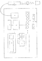
以下、本発明の装置を図面に基づき説明する。図1は本発明の装置を適用した免疫化学的分析装置の一例を示すブロック図である。1はスイッチを設けた手持ちノズル装置、2はポンプ装置、3は移送装置の反応容器保持部、4はB/F分離装置、5試薬分注装置、6は検出装置、7は計時装置を兼ねる制御装置、8は表示装置、9は操作パネル(入力装置)、10は出力装置(プリンタ)である。である。本例では、移送装置の容器保持部は不図示の駆動手段の働きにより横方向に移動し、容器保持部に載置された反応容器をB/F分離装置、試薬分注装置及び検出装置の直下に移送可能である。なお、本例では図示していないが、移送装置による容器保持部の移送経路の直下には反応容器中の溶液を温調するための温調装置及び容器を撹拌するための磁石装置が取り付けられている。反応容器中には常磁性物質であるフェライトが埋設された直径約1.5mmの担体であって、分析されるべき抗原に対する抗体が固定化された担体が予め入れられており、この磁石装置の働きにより担体を運動させることで溶液を撹拌するように構成してある。
【0026】
本例の分析装置では、反応容器には測定されるべき抗原に対する第1の抗体が固定化された前記担体、及び、第1の抗体とは異なる部位を認識する抗体であって、酵素と結合された第2の抗体が予め投入され、凍結乾燥されている。従って、手持ちノズル1に設けられたスイッチを操作して凍結乾燥された試薬を溶解するための試薬溶解液と試料液体を吸引し、反応容器に吐出すると同時に免疫反応が開始される。従って、手持ちノズル1の吐出スイッチが押された時、或いはその前後の時点を起点として制御装置7は当該反応容器に関する計時操作を開始する。またこれと同時に制御装置7は、当該反応容器に関する時間管理を実現するため、操作者に対して当該反応容器を載置すべき移送装置上の保持部を指定し、表示装置8に出力する。従って操作者は試料液体を吐出後、反応容器を指定された保持部に載置するのみで免疫化学的分析を実施することができる。
【0027】
本例の装置では、免疫反応開始から10分経過後にB/F分離操作、抗体と結合された酵素の活性を測定するための試薬(酵素基質)の分注操作、酵素活性の検出操作という一連の操作が開始されるように制御装置7にパラメータを入力してある。このため制御装置7は、前記のようにして免疫反応が開始された後9分30秒が経過すると移送装置を駆動して該当する反応容器を順次B/F分離装置、試薬分注装置、検出装置に移送するように構成されているが、これに先立ち、操作者に対し新たに反応容器に試料液体を吐出しないように表示装置8に警告を表示し、かつ、手持ちノズルの試料液体吐出のためのスイッチングを無効にして操作者のミスを防止する。
【0028】
これ以外にも制御装置7は、移送装置上の容器保持部に空きがなくなった場合や後の操作に支障を与えかねない場合等に同様の警告を表示し、手持ちノズルの吐出スイッチングを無効にする。
【0029】
B/F分離装置、試薬分注装置、検出装置による操作が完了すると、制御装置7は、検出装置からの検出結果を予め入力された検量線データと比較し、測定されるべき抗原の濃度を計算して出力装置(プリンタ、10)に出力する。各装置による操作が完了した反応容器については、制御装置7が表示装置8に廃棄を許可する表示を行なう。操作者が不要の反応容器を廃棄して移送装置の保持部に空きができたりB/F分離に続く一連の操作に支障がないと制御装置7が判断した場合、試料液体の吐出を禁止する旨の警告を解除し、手持ちノズル装置1のスイッチングを有効にする。
【0030】
【発明の効果】
本発明の装置によれば、試料液体の吸引・吐出は操作者が手動で行うため、試料容器を保持・移送する機構及びノズル装置を保持・移動する機構に加え、この操作を自動的に行なう際に必要な、試料液体の液面レベルの検出機構をも省略することができる。この結果本発明の装置は、全自動分析装置に比較して簡便な構成とすることができるから、小型で安価に提供することが可能となる。
【0031】
本発明の装置によれば、操作者が試料液体を反応容器に吐出した時点等を起点として反応容器ごとに反応時間等を管理することができる。この結果本発明の装置は、分析における正確な時間管理を通じて分析結果の再現性等を向上することが可能である。
【図面の簡単な説明】
【図1】図1は本発明の分析装置の一例を示す図である。
【符号の説明】
1 手持ちノズル装置
2 ポンプ装置
3 移送装置(移送装置の容器保持部)
4 B/F分離装置
5 試薬分注装置
6 検出装置
7 制御装置
8 表示装置
9 操作パネル
10 出力装置(プリンタ)[0001]
[Industrial application fields]
The present invention relates to a biochemical analyzer for analyzing a specific component in a liquid sample derived from a living body such as serum or urine chemically, enzymologically or immunochemically.
[0002]
[Prior art]
In general biochemical analysis, a sample and a reagent are mixed and reacted at a predetermined temperature for a certain period of time, and a change that occurs as a result of the reaction is performed by, for example, an optical method, for example, after the start of the reaction, before or after the reaction or in the course of the reaction. Measure multiple times with. Further, after mixing the sample and the reagent, the second and third reagents may be further dispensed during the reaction.
[0003]
For example, in an immunochemical analysis method, a homogeneous measurement system and a heterogeneous measurement system are known. The former is performed in the same manner as a general biochemical analysis, and the latter is added with a process of so-called B / F separation (separation of Bound and Free). This step is a step of separating the binding component bound to the water-insoluble carrier and the component not bound to the carrier present in the solution by washing the inside of the reaction vessel with a washing liquid.
[0004]
[Problems to be solved by the invention]
Conventional biochemical analysis is performed by semi-automatic analyzers that perform some operations by hand and fully automatic analyzers that automatically perform all operations, but the progress of the reaction depends on time, so each It is necessary to perform the analysis operation within a certain time. In a fully automatic analyzer, since all operations are commanded by a control device or the like, it is possible to always analyze a plurality of samples under the same conditions. On the other hand, in the semi-automatic analyzer, the operator needs to operate so that the reaction time becomes constant while looking at the clock.
[0005]
The fully automatic analyzer requires many complicated mechanisms for automatically performing all operations, and there is a problem that the apparatus is increased in size and cost. On the other hand, in the semi-automatic analyzer, it is possible to simplify the device mechanism compared to the fully automatic analyzer, but not only the reaction time etc. become inaccurate because manual operation is included in part of the operation, There is a problem that once an analysis is started, it cannot be released during the analysis.
[0006]
[Means for Solving the Problems]
SUMMARY OF THE INVENTION In view of the above problems, the present invention has been made with the object of providing a simple semi-automatic analyzer that enables accurate time management, and at least semi-manually performs suction and discharge of a sample liquid. Hand-held nozzle device, pump device connected to the hand-held nozzle device directly or via a pipe, reaction vessel from which sample liquid is discharged, reaction vessel transfer device for holding a plurality of reaction vessels and transferring them along a transfer path This is a biochemical analyzer comprising a timing device and a control device that controls the device in conjunction with the timing device. Hereinafter, the present invention will be described in detail.
[0007]
As the hand-held nozzle device, those used in the normal biochemical field can be used. For example, a pipette device using a thin tube or a disposable tip connected to the pump device directly or via a pipe. It is only necessary that the sample, the sample-to-sample solution, the sample-to-sample dilution solution, and the like necessary for such a thin tube or chip can be aspirated and then discharged into the reaction vessel. The number of nozzle devices does not need to be one, and for example, a plurality of nozzle devices connected to the same or different pump devices directly or via piping may be used. In order to prevent contamination between the sample liquids, it is preferable to clean the thin tubes and the like every time the sample liquid is changed, and in the case of a disposable tip, replace with a new one every time the sample liquid is changed. As a pump device connected to the nozzle device, for example, a normal syringe pump or plunger pump can be used. This pump device may be integrated into the nozzle device, or may be configured separately from the nozzle device and connected by piping.
[0008]
Although the hand-held nozzle device may be operated completely manually, it is preferable that the hand-held nozzle device is connected to the control device via a timing device from the viewpoint of time management described later. That is, for example, a switch for sucking and discharging a liquid sample is provided in the handheld nozzle device, and when this switch is pressed, the timekeeping operation of the timekeeping device is started and the control device receives the input to receive the sample in the handheld nozzle device. The pump device may be driven to suck or discharge liquid, or a solenoid valve may be installed between the drive device and the hand-held nozzle device, and the control device may be configured to open and close the solenoid valve in response to input. It can be illustrated. Of course, as will be described later, when the timing operation of the timing device is started using a switch provided separately or a sensor provided in the transfer device, the sample liquid or the like is sucked and / or discharged when this switch is pressed. It can also be configured to be performed only.
[0009]
The discharge of the sample liquid in the hand-held nozzle device usually means the start of analysis. For example, when analyzing a plurality of samples in immunochemical analysis, since there are operations that need to be performed after a certain time from the start of reaction for each reaction vessel, such as B / F separation and detection operation, a hand-held nozzle If the sample liquid is discharged randomly, the processing of the analyzer may be affected. For example, although it takes a certain time to perform the B / F separation operation, etc., the reaction container which started the analysis after discharging the sample liquid into two or more reaction containers within the certain time and starting the analysis later Occurs that B / F separation cannot be performed at an appropriate time. In order to avoid this, if the hand-held nozzle device is connected to the control device and there is a possibility that the above-mentioned trouble may occur in the subsequent operation, the control device rejects the sample liquid even if the discharge switch is pressed. It is preferable to prevent the ink from being discharged, or to prohibit pressing the switch itself. In addition, a configuration in which the operator can be visually or audibly informed that the discharge switch can be pressed using a display device described later (or vice versa) is not possible. Of course, whether or not a failure occurs in the subsequent operation depends on the processing capability of the entire apparatus and the content of analysis, and therefore the details need to be determined as appropriate. For example, in the above example, the situation differs when the B / F separator can process two or more reaction vessels at the same time and when only one reaction vessel can be processed. This is because it may be allowed for reasons such as not having an influence.
[0010]
Thus, even if the operator presses the discharge switch of the sample liquid, if the control device may refuse this or prohibit the pressing of the switch itself, in order to facilitate the operator's situational recognition, It is preferable that a display device connected to the control device is installed to display the fact. In addition to displaying whether or not the sample liquid can be discharged into the reaction container, this display device can also have a function as described later.
[0011]
When a switch is provided in a hand-held nozzle device, there is no limit on the number thereof. For example, two single push-down buttons are provided, one for sucking and discharging the sample liquid, the other for sucking and discharging the sample liquid, and the other for sucking and discharging the other liquid. Can be illustrated. When one switch is used, it may be configured such that suction and discharge can be performed by pressing down once and continuously pressing down twice. Such a switch is not necessarily provided in the hand-held nozzle body, and can be provided separately from the body. For example, a switch can be exemplified as a foot pedal.
[0012]
Examples of the liquid sample in the present invention include, but are not limited to, samples prepared from blood derived from a living body such as human serum and urine. A certain amount of the biological sample is sucked by a hand-held nozzle device and discharged to the reaction container. In the reaction container, a reagent necessary for analyzing the sample liquid may be input in advance. For example, when performing an immunochemical analysis, an antibody against a specific substance in a sample liquid bound to a water-insoluble carrier and an antibody against a specific substance bound to a labeling substance such as an enzyme may be included. This is a reagent configuration in the case of performing an analysis using a so-called one-step sandwich method (simultaneous sandwich method or a simulated sandwich method). It is also possible to use a container in which only an antibody against a specific substance in the bound sample liquid is introduced, and then inject an antibody against the specific substance bound to a labeling substance such as an enzyme. When analysis is performed using a so-called competitive method, for example, a reaction in which an antibody against a specific substance in a sample liquid bound to a water-insoluble carrier, a specific substance analog in which a specific substance and a labeling substance such as an enzyme are bound, is input in advance. Use a container.
[0013]
The reaction container charged with the sample liquid is placed on the transfer device. The transfer device is not particularly limited as long as it can hold a plurality of reaction vessels and can transfer them along the transfer path. Further, for example, in addition to the reaction vessel, reagents used in the subsequent analysis operation may be held. Examples of such a reagent include an antibody against a specific substance bound to a labeling substance such as an enzyme in the case of using the above-described two-step sandwich method, an enzyme substrate in the case of using an enzyme as a labeling substance, and the like.
[0014]
The transfer device may comprise, for example, a reaction vessel holding unit for holding the reaction vessel, a driving means for moving the reaction vessel holding unit, a transfer path, and the like. It is good also as a structure to rotate. The former case is effective in that the transfer path can be either a straight line or a curved line. The latter is effective in that the apparatus itself can be miniaturized although the transfer path itself is limited to the circumferential direction of the disk. In addition to such a configuration, for example, the reaction vessel can be moved to a separately configured transfer path using a means such as an arm that can capture the reaction vessel from the reaction vessel holding unit.
[0015]
The reaction container holding part of the transfer device is assigned a number for the control device described later to manage the reaction container. Based on this number or the like, the control device performs time management such as reaction time for each reaction container, and manages so that a predetermined operation is performed at a predetermined time. The operator dispenses the sample liquid into the reaction vessel, places it on the reaction vessel holding part of the transfer device, and automatically inputs the number etc. to the control device. Analysis will be conducted. On the other hand, for example, the control device is made to output a suitable mounting location in the form of the number or the like, or a display lamp is provided for each reaction container holding unit, and the preferable mounting is performed. It is also possible to adopt a configuration in which the reaction container is placed at a designated site, for example, by turning on the display lamp of the placement location. In this case, in order to facilitate parallel processing while managing the time for a plurality of reaction vessels, the control device has already started the time management as a container holding part of the reaction vessel transfer device on which the reaction vessel should be placed. It is also possible to exemplify a configuration in which a placement location that is separated from the placement location is designated. In addition, a sensor that detects whether or not the reaction container is placed on the reaction container holding portion of the transfer device is installed, and the operator automatically places the reaction container that has discharged the sample liquid on the transfer device. It is also possible to have a configuration in which the place where the device is placed is grasped and time management is performed.
[0016]
In the case where the placement location of the reaction container suitable for time management is output from the control device, a display device for displaying whether or not the sample liquid can be discharged by the hand-held nozzle device can also be used as the output destination. Further, with this display device, for example, when the disk-shaped reaction vessel transfer device is about to start rotation upon receiving an instruction from the control device, the time until the rotation starts or the operator is prohibited from placing the reaction vessel. It can also be displayed. This display device may display these items visually, for example, or may display these items by a warning sound or the like. Further, the display device can display the place where the analysis has been completed and the like with the above-mentioned numbers. As a result, the operator can easily identify the reaction container that is no longer needed and discard it.
[0017]
For example, in an immunochemical analyzer, a B / F separation device, a reagent dispensing device, a detection device, and the like are installed in the transfer path. The B / F separation device is a device for discharging the washing liquid into the reaction vessel and discharging the liquid from the reaction vessel. In the heterogeneous immunoassay using a water-insoluble carrier, the B / F separation device binds to the label component and the carrier. Separation of unlabeled labeling components is performed. For example, the apparatus may be configured by a pipe for discharging the cleaning liquid, a pipe for discharging the liquid in the reaction vessel, and a driving means for moving these pipes up and down. As the reagent dispensing device, a normal dispensing device configured by a thin tube or a disposable chip connected directly to the pump device or via a pipe can be used. With this apparatus, for example, as described above, an amount of an antibody against a specific substance bound to a labeling substance such as an enzyme in the case of using the two-step sandwich method or an enzyme substrate in the case of using an enzyme as the labeling substance is aspirated, Discharge into the reaction vessel. In this case, as long as the same reagent is dispensed, it can be used without washing the thin tube and without changing the disposable tip. The detection device installed in the transfer path is appropriately selected depending on the contents of analysis. For example, a colorimeter or the like may be selected when color develops due to the reaction, a fluorometer when the reaction solution emits fluorescence due to the reaction, and a luminescence detector when the reaction solution emits light due to the reaction. In addition to such an optical detection device, for example, an ammeter can be used depending on the content of the reaction. The detection by the detection device may be performed, for example, while maintaining the reaction solution in the reaction vessel, or may be performed by collecting a certain amount of the reaction solution. Thus, the apparatus for performing various operations required in order to perform analysis is arrange | positioned at a transfer path.
[0018]
In many cases, it is preferable to install a temperature control device for controlling the temperature of the reaction liquid in the reaction vessel in the transfer path. For example, it is possible to exemplify arranging a water bath below the transfer path or configuring the path itself with a heating element. As a result, analysis can always be performed at a constant temperature, and analysis with higher reproducibility can be realized. Moreover, it is preferable to install a stirring device for stirring the reaction liquid in the reaction vessel in the transfer path. For example, a stirrer that can be moved up and down can be used as an example. For example, a stirrer that moves with a magnet device can be put in a reaction vessel in advance. In particular, in an immunochemical analysis using a water-insoluble carrier, it is convenient to use a resin or the like in which ferrite or the like is embedded as the carrier. And if a magnet apparatus is installed in the lower part of a transfer apparatus and this is reciprocated, stirring operation is realizable. This makes it possible to promote the reaction.
[0019]
The various devices described above do not necessarily have to be installed on the transfer path of the reaction vessel. For example, the reaction vessel on the transfer device may be moved to each device using a reaction vessel capturing means such as an arm. .
[0020]
The control device according to the present invention includes a microprocessor and peripheral components, and is connected to various devices. In the microprocessor, for example, driving means such as a motor of a transfer device, a driver circuit that drives the vertical movement of a tube for B / F separation, liquid to the hand-held nozzle device, reagent dispensing device, B / F separation device, etc. A drive circuit or the like for driving a solenoid valve installed between the pump means and these devices for suction (discharge) or discharge is connected. Further, the control device is preferably connected to the detection device and outputs a final analysis result based on the detection result. In order to realize this effect, it is preferable to connect a display unit, an operation panel having keys for input, a printer for outputting analysis results, and the like to the control device. By connecting such peripheral devices, the analysis result can be displayed immediately and output to paper by a printer. Here, the display device described so far can also be used as an output destination of analysis results. If a communication port with an external computer is provided, the final analysis result can be output to the external computer. In order to output the analysis result, it is preferable that calibration curve information and the like used for calculating the concentration and the like of the analyte can be stored or input.
[0021]
As described above, if the hand-held nozzle device and the control device are connected and various information such as the amount of sample liquid required according to the analysis content is input to the control device, the operator can connect to the nozzle device. Necessary operations can be completed only by operations such as pressing a provided switch. For this purpose, the control device is configured to store in advance the amount of sample liquid, the amount of reagent, the amount of diluted liquid sample, etc. required for each analysis item, or to be able to input as necessary. Is preferred.
[0022]
In the timing device, the microprocessor may also have the function, but when it is installed separately, it is connected to the microprocessor. The timing device measures the elapsed time for each reaction vessel. In order to measure the elapsed time for each reaction container, the transfer device is assigned a number or the like to the place where the reaction container is placed. The control device performs time management for each reaction container based on the elapsed time for each reaction container timed by the time measuring device. Therefore, it is preferable that the control device stores various parameters according to the analysis contents, for example, reaction time, reagent dispensing volume, and the like, or allows input from a key or the like. For example, in an immunochemical reaction, even when analyzing the same sample, the reaction time between the antibody bound to the carrier or the antibody bound to the label and the sample liquid and the amount of reagent to be dispensed later is different if the analysis target is different. It may be different or the reaction time itself may be different. Therefore, for example, it is preferable that the analysis content is input to the control device prior to the analysis, and the reaction conditions including the reaction time are managed according to the input information.
[0023]
In order to time the elapsed time for each reaction container, for example, it is possible to exemplify that the time measuring device is configured so as to start from the time when the liquid sample starts to be discharged to the reaction container. For example, as described above, when a switch for sucking and discharging a liquid sample is provided in the hand-held nozzle device and the liquid sample is sucked and discharged through the control device, when the discharge switch is pressed Can be set as the starting point of the timing device. Such a configuration is particularly preferred when the reaction according to the analysis content is started simultaneously with the discharge of the sample liquid into the reaction vessel. However, in an analysis in which the time required for the discharge of the sample liquid is extremely short, such as when the amount of the discharged sample liquid is about several tens of μl, such as immunochemical analysis, the sample liquid with respect to the reaction vessel You may time from the time of completion of discharge. In order to operate the timing device in this way, for example, a switch for starting the operation of the timing device (time counting operation) is provided, and the operator presses this switch when the sample liquid is discharged into the reaction solution. However, in order to reduce the burden on the operator and prevent mistakes such as forgetting to press the switch, a sensor for detecting the presence or absence of the container is preferably provided on the container holding stand, and the operator reacts after discharging the sample liquid. It is preferable to automatically detect that the container has been placed on the holding table and start the timing operation of the timing device. This sensor can also be used as a sensor for automatically detecting the place where the reaction container is placed.
[0024]
The switch provided on the hand-held nozzle as described above, the switch provided separately from the hand-held nozzle, or the sensor provided on the container holding unit is connected to the timing device, and starts when the operator presses the switch. As a result, the timing operation starts. Since the timing device is connected to the control device as described above, and the container holding portion of the transfer device is assigned a number, etc., the control device manages the reaction time for each reaction container, and according to the analysis contents For example, in the case of immunochemical analysis, a B / F separation operation, a reagent dispensing operation, a detection operation, and the like can be automatically performed after a reaction that has been stored in advance or input. Further, unlike such control, the timing device can be always operated, and the control device can be configured to permit the discharge of the sample liquid only when it is convenient to control the reaction. For example, a configuration in which ejection is allowed for 5 seconds every 30 seconds can be exemplified. If the permitted time width (5 seconds in the above example) is sufficiently short with respect to the actual reaction time (for example, 10 minutes) that is subsequently performed, and when the discharge is performed in the initial stage of the time width and the time width The time difference when the discharge is performed in the later stage can be ignored.
[0025]
The apparatus of the present invention will be described below with reference to the drawings. FIG. 1 is a block diagram showing an example of an immunochemical analyzer to which the apparatus of the present invention is applied. 1 is a hand-held nozzle device provided with a switch, 2 is a pump device, 3 is a reaction container holding unit of a transfer device, 4 is a B / F separation device, 5 reagent dispensing device, 6 is a detection device, and 7 is also a timing device A control device, 8 is a display device, 9 is an operation panel (input device), and 10 is an output device (printer). It is. In this example, the container holding part of the transfer device is moved in the lateral direction by the action of a driving means (not shown), and the reaction vessel placed on the container holding part is moved to the B / F separation device, the reagent dispensing device, and the detection device. It can be transferred directly below. Although not shown in the present example, a temperature adjusting device for adjusting the temperature of the solution in the reaction vessel and a magnet device for stirring the vessel are attached immediately below the transfer path of the container holding unit by the transfer device. ing. In the reaction vessel, a carrier having a diameter of about 1.5 mm in which ferrite, which is a paramagnetic substance, is embedded, and a carrier on which an antibody against an antigen to be analyzed is immobilized is placed in advance. The solution is stirred by moving the carrier by the action.
[0026]
In the analyzer of this example, the reaction container is the carrier on which the first antibody against the antigen to be measured is immobilized, and the antibody that recognizes a site different from the first antibody, and binds to the enzyme. The second antibody thus prepared is previously introduced and lyophilized. Accordingly, the reagent solution for dissolving the freeze-dried reagent and the sample liquid are aspirated by operating a switch provided in the hand-held nozzle 1 and discharged into the reaction container, and at the same time, an immune reaction is started. Therefore, when the discharge switch of the hand-held nozzle 1 is pressed, or starting from before and after that point, the control device 7 starts a time measuring operation related to the reaction container. At the same time, the control device 7 designates a holding unit on the transfer device on which the reaction container is to be placed and outputs it to the
[0027]
In the apparatus of this example, a series of B / F separation operation, dispensing operation of a reagent (enzyme substrate) for measuring the activity of the enzyme bound to the antibody, and detection operation of the enzyme activity after 10 minutes from the start of the immune reaction. Parameters are input to the control device 7 so that the above operation is started. For this reason, the control device 7 drives the transfer device when 9 minutes and 30 seconds have elapsed after the immune reaction has been started as described above, and sequentially selects the corresponding reaction container from the B / F separation device, the reagent dispensing device, and the detection device. Prior to this, a warning is displayed on the
[0028]
In addition to this, the control device 7 displays a similar warning when the container holding part on the transfer device runs out of space or may interfere with the subsequent operation, and disables the discharge switching of the hand-held nozzle. To do.
[0029]
When the operation by the B / F separation device, the reagent dispensing device, and the detection device is completed, the control device 7 compares the detection result from the detection device with the calibration curve data input in advance, and determines the concentration of the antigen to be measured. Calculate and output to the output device (printer, 10). For the reaction vessel for which the operation by each device has been completed, the control device 7 displays on the
[0030]
【The invention's effect】
According to the apparatus of the present invention, since the sample liquid is sucked and discharged manually, the operation is automatically performed in addition to the mechanism for holding and transferring the sample container and the mechanism for holding and moving the nozzle device. In this case, it is possible to omit the liquid level detection mechanism of the sample liquid. As a result, the apparatus of the present invention can be provided with a simpler configuration as compared with the fully automatic analyzer, and therefore can be provided in a small size and at a low cost.
[0031]
According to the apparatus of the present invention, the reaction time and the like can be managed for each reaction container, starting from the time when the operator discharges the sample liquid to the reaction container. As a result, the apparatus of the present invention can improve the reproducibility of the analysis result through accurate time management in the analysis.
[Brief description of the drawings]
FIG. 1 is a diagram showing an example of an analyzer according to the present invention.
[Explanation of symbols]
1 Hand-held
4 B / F separation device 5 Reagent dispensing device 6 Detection device 7
Claims (12)
Priority Applications (1)
| Application Number | Priority Date | Filing Date | Title |
|---|---|---|---|
| JP18594796A JP3728811B2 (en) | 1996-07-16 | 1996-07-16 | Biochemical analyzer |
Applications Claiming Priority (1)
| Application Number | Priority Date | Filing Date | Title |
|---|---|---|---|
| JP18594796A JP3728811B2 (en) | 1996-07-16 | 1996-07-16 | Biochemical analyzer |
Publications (2)
| Publication Number | Publication Date |
|---|---|
| JPH1031025A JPH1031025A (en) | 1998-02-03 |
| JP3728811B2 true JP3728811B2 (en) | 2005-12-21 |
Family
ID=16179669
Family Applications (1)
| Application Number | Title | Priority Date | Filing Date |
|---|---|---|---|
| JP18594796A Expired - Fee Related JP3728811B2 (en) | 1996-07-16 | 1996-07-16 | Biochemical analyzer |
Country Status (1)
| Country | Link |
|---|---|
| JP (1) | JP3728811B2 (en) |
Families Citing this family (1)
| Publication number | Priority date | Publication date | Assignee | Title |
|---|---|---|---|---|
| JP2016106214A (en) * | 2013-02-20 | 2016-06-16 | 株式会社日立ハイテクノロジーズ | Autoanalyzer |
-
1996
- 1996-07-16 JP JP18594796A patent/JP3728811B2/en not_active Expired - Fee Related
Also Published As
| Publication number | Publication date |
|---|---|
| JPH1031025A (en) | 1998-02-03 |
Similar Documents
| Publication | Publication Date | Title |
|---|---|---|
| JP3990944B2 (en) | Automatic analyzer | |
| JP2539512B2 (en) | Multi-item analyzer and method for operating the analyzer | |
| EP1826572B1 (en) | Analyzer with scheduling verification | |
| EP3432003B1 (en) | Automated analysis device | |
| US6579717B1 (en) | Specific solution handling method for calibration and quality control by automatic analytical apparatus | |
| JP2019215357A (en) | Automatic analysis device and automatic analysis method | |
| EP1102994B1 (en) | Automated immunoassay apparatus with flexible pick-up arm | |
| JP2525063B2 (en) | Automatic analysis method | |
| JP2001091523A (en) | Automatic analyzer | |
| CA2392943A1 (en) | Chemistry system for a clinical analyzer | |
| JP2001504577A (en) | Automatic chemical analyzer | |
| JPH1062432A (en) | Automatic sample pretreatment device and automatic sample pretreatment method | |
| CN101393223A (en) | Specimen analyzer and liquid suction assembly | |
| JP6900268B2 (en) | Automatic analyzer | |
| JP2611609B2 (en) | Clinical compound analyzer | |
| JP3728811B2 (en) | Biochemical analyzer | |
| CN114902053A (en) | Automatic analyzer, display system for automatic analyzer, and display method for automatic analyzer | |
| CN113039438A (en) | Automatic analyzer | |
| JP2590688Y2 (en) | Blood coagulation analyzer | |
| JPH05172828A (en) | Automatic analyser | |
| JP3632537B2 (en) | Automatic analyzer and analysis method using the same | |
| JPH08105901A (en) | Automatic analyzing device | |
| JP3952182B2 (en) | Liquid level detection method in dispenser | |
| JP2001004636A (en) | Automatic analyzer | |
| JPH08313536A (en) | Analysis equipment |
Legal Events
| Date | Code | Title | Description |
|---|---|---|---|
| A977 | Report on retrieval |
Effective date: 20040722 Free format text: JAPANESE INTERMEDIATE CODE: A971007 |
|
| A131 | Notification of reasons for refusal |
Free format text: JAPANESE INTERMEDIATE CODE: A131 Effective date: 20041116 |
|
| A521 | Written amendment |
Free format text: JAPANESE INTERMEDIATE CODE: A523 Effective date: 20050117 |
|
| A131 | Notification of reasons for refusal |
Free format text: JAPANESE INTERMEDIATE CODE: A131 Effective date: 20050215 |
|
| A521 | Written amendment |
Free format text: JAPANESE INTERMEDIATE CODE: A523 Effective date: 20050418 |
|
| TRDD | Decision of grant or rejection written | ||
| A01 | Written decision to grant a patent or to grant a registration (utility model) |
Free format text: JAPANESE INTERMEDIATE CODE: A01 Effective date: 20050913 |
|
| A61 | First payment of annual fees (during grant procedure) |
Free format text: JAPANESE INTERMEDIATE CODE: A61 Effective date: 20050926 |
|
| FPAY | Renewal fee payment (prs date is renewal date of database) |
Year of fee payment: 3 Free format text: PAYMENT UNTIL: 20081014 |
|
| FPAY | Renewal fee payment (prs date is renewal date of database) |
Year of fee payment: 4 Free format text: PAYMENT UNTIL: 20091014 |
|
| FPAY | Renewal fee payment (prs date is renewal date of database) |
Free format text: PAYMENT UNTIL: 20091014 Year of fee payment: 4 |
|
| FPAY | Renewal fee payment (prs date is renewal date of database) |
Year of fee payment: 5 Free format text: PAYMENT UNTIL: 20101014 |
|
| FPAY | Renewal fee payment (prs date is renewal date of database) |
Year of fee payment: 6 Free format text: PAYMENT UNTIL: 20111014 |
|
| FPAY | Renewal fee payment (prs date is renewal date of database) |
Year of fee payment: 6 Free format text: PAYMENT UNTIL: 20111014 |
|
| FPAY | Renewal fee payment (prs date is renewal date of database) |
Free format text: PAYMENT UNTIL: 20121014 Year of fee payment: 7 |
|
| FPAY | Renewal fee payment (prs date is renewal date of database) |
Year of fee payment: 8 Free format text: PAYMENT UNTIL: 20131014 |
|
| LAPS | Cancellation because of no payment of annual fees |