JP3728362B2 - Speed switching mechanism - Google Patents
Speed switching mechanism Download PDFInfo
- Publication number
- JP3728362B2 JP3728362B2 JP05181697A JP5181697A JP3728362B2 JP 3728362 B2 JP3728362 B2 JP 3728362B2 JP 05181697 A JP05181697 A JP 05181697A JP 5181697 A JP5181697 A JP 5181697A JP 3728362 B2 JP3728362 B2 JP 3728362B2
- Authority
- JP
- Japan
- Prior art keywords
- bearing
- speed
- toothed
- gear
- rotated
- Prior art date
- Legal status (The legal status is an assumption and is not a legal conclusion. Google has not performed a legal analysis and makes no representation as to the accuracy of the status listed.)
- Expired - Fee Related
Links
Images
Landscapes
- Gear Transmission (AREA)
- Structure Of Transmissions (AREA)
- Connection Of Motors, Electrical Generators, Mechanical Devices, And The Like (AREA)
Description
【0001】
【発明の属する技術分野】
本発明は、速度切換機構に関し、特に、互いに間隔をおいて設けられた各軸受円板間に、互いに径の異なる減速ギヤを有する複数の中間軸を設け、この各中間軸を選択することにより容易に被回転体の速度を切換えるための新規な改良に関する。
【0002】
【従来の技術】
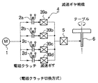
従来、用いられていたこの種の速度切換機構としては、一般に、図4及び図5で示す構成が採用されていた。すなわち、図4の電磁クラッチ切換方式の場合、モータ1は並列接続された各電磁クラッチ2a〜2nに接続され、各電磁クラッチ2a〜2nは互いに減速比の異なる各減速ギヤ3a〜3nが接続されている。従って、前記各電磁クラッチ2a〜2n及び各減速ギヤ3a〜3nによって可変型の減速ギヤ機構4を構成している。この減速ギヤ機構4はカップラー5を介してテーブル等の被回転体6に接続されている。
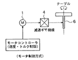
また、図5のモータ制御方式の場合、速度及びトルク制御が自在なモータコントローラ10にモータ1が制御されるように構成され、このモータ1が単体の減速ギヤ機構4を介して被回転体6に接続されている。
【0003】
【発明が解決しようとする課題】
従来の速度切換機構は、以上のように構成されていたため、次のような課題が存在していた。
すなわち、図4の従来構成の場合、純機械式の複数の減速ギヤによって減速ギヤ機構を構成するため、回転音が極めて大きく、さらにはスペースを大きく確保しなければならなかった。また、速度切換はクラッチで切換えるため、開閉頻度が高いとスリップ等の故障や不具合が発生していた。
また、図5の従来構成の場合、モータ速度を制御するコントローラが必要となり、迅速な減速切換は困難であった。
また、モータのトルクが確保できる速度範囲に制御は限られていた。
【0004】
本発明は、以上のような課題を解決するためになされたもので、特に、互いに間隔をおいて設けられた各軸受円板間に、互いに径の異なる減速ギヤを有する複数の中間軸を設け、この各中間軸を選択することにより容易に被回転体の速度を切換えるようにした速度切換機構を提供することを目的とする。
【0005】
【課題を解決するための手段】
本発明による速度切換機構は、モータの回転を減速ギヤ機構の各減速ギヤを選択してテーブルからなる被回転体に伝達することにより、前記被回転体の回転速度を切換えるようにした速度切換機構において、前記減速ギヤ機構は、一対の固定された軸受ホルダ間に回転自在に設けられ主ギヤを有すると共に前記被回転体に接続された主軸と、前記主軸に設けられ支柱により互いに間隔をおいて並設され一体回転する歯付軸受円板及びキー溝付軸受円板と、前記各軸受円板間に回転自在に設けられた複数の中間軸と、前記各中間軸に設けられ互いに径の異なる減速ギヤと、前記各中間軸に設けられ前記モータのモータギヤにより駆動される駆動ギヤと、前記キー溝付軸受円板に設けられ半径方向に深さを有すると共に円周の所定角度毎に形成された複数のキー溝と、前記各キー溝に対して係合及び離脱自在にばねで付勢された突起体と、前記突起体をワイヤを介して作動させるため作動スイッチに接続されたアクチュエータと、前記歯付軸受円板の歯部と噛合する歯付軸受円板駆動ギヤと、前記歯付軸受円板駆動ギヤにギヤ機構を介して接続された設定ツマミ及び速度指示器とよりなり、前記アクチュエータにより前記ワイヤを介して前記突起体を前記キー溝から離脱させ、前記ツマミによって前記歯付軸受円板と共に前記キー溝付軸受円板を回転させ、前記アクチュエータの非駆動により前記突起体が前記キー溝内に係合して前記キー溝付軸受円板が位置決めされ、前記各中間軸の各減速ギヤを前記各主ギヤに選択的に噛合させることにより前記主軸に設けられた前記被回転体の速度を自在に切換える構成である。
【0006】
【発明の実施の形態】
以下、図面と共に本発明による速度切換機構の好適な実施の形態について説明する。なお、従来例と同一又は同等部分には同一符号を付して説明する。
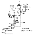
図1は本発明の全体構成を示すもので、モータ1は減速ギヤ機構4を介してテーブルからなる被回転体6に接続され、この減速ギヤ機構4には歯部20aを有する歯付軸受円板20及び複数のキー溝21aを有するキー溝付軸受円板21を有している。前記各キー溝21aはキー溝付軸受円板21の半径方向に深さを有すると共に円周の所定角度毎に形成されている。前記歯部20aに噛合した歯付軸受円板駆動ギヤ22はギヤ機構23を介して設定ツマミ24及び速度指示器25に接続されている。
前記キー溝21aには、ソレノイド等のアクチュエータ6によりワイヤ26a及びばね27a付勢により出入する突起体27が係合及び離脱自在に設けられており、このアクチュエータ26は電源28及び作動スイッチ29に接続されている。
【0007】
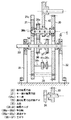
前記減速ギヤ機構4を構成する主部材としての前記歯付軸受円板20及びキー溝付軸受円板21は、互いに所定の間隔を保つように複数の支柱30によって一体状に保持されていると共に1対の軸受ホルダ31,32間に回転自在に設けられた主軸33に留め具34,35を介して一体的に設けられている。前記主軸33には互いに径の異なる複数の主ギヤ36,37が設けられている。
【0008】
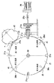
前記各軸受円板20,21間には、この形態では4個の中間軸38a〜38dが回転自在に設けられ、これらの中間軸38a〜38dは図3で示されるようにキー溝付軸受円板21の円周上の4箇所(90度ごと)に設けられ、各中間軸38a〜38dには、各中間軸38a〜38dごとに径の異なる減速ギヤ39a〜39d(39b,39dは図示せず)とモータ1に接続されたモータギヤ40と噛合する径の一定な駆動ギヤ41とが設けられてする。従って、このキー溝付軸受円板21を前記ツマミ24によって歯付軸受円板20と共に回転させることにより、各90度位置で突起体27によって位置決めされると共に、各中間軸38a〜38dが図3で示す第1減速から第4減速として減速設定位置Aに選択的な位置決めされるように構成されている。
【0009】
次に、動作について述べる。図2の状態は、中間軸38aが第1減速として位置し、駆動ギヤ41がモータギヤ40と噛合していると共に減速ギヤ39aが主ギヤ36と噛合することによって前記第1減速の減速比が構成され、この状態でモータ1を駆動することにより主軸33が回転し、この主軸33に接続された被回転体6が回転される。
次に、第3減速に変更する場合、アクチュエータ26を駆動してワイヤ26aを介してばね27aのばね力に抗して突起体27をキー溝21aから離脱させると、各軸受円板20,21は回転自在となる。この状態で、ツマミ24を回転させると、歯付軸受円板駆動ギヤ22を介して歯付軸受円板20と共にキー溝付軸受円板21が回転し、第3減速が減速設定位置Aに位置した状態でアクチュエータ26を非駆動に作動させて突起体27をばね27aの復帰力により戻してキー溝21aに係合して位置決めすることにより切換動作が終了する。従って、第3減速として中間軸38cが図2で示す中間軸38aの位置に回転移動したことになり、第1中間軸38aの中間ギヤ39aとは径が異なる第3中間軸38cの中間ギヤ39cが主ギヤ37と噛合することになり、第1減速とは異なる減速比に速度切換がなされる。すなわち、前述の各軸受円板20,21を回転して第1〜第4減速(より多くの減速も可)を任意に選択することができる。
【0010】
【発明の効果】
本発明による速度切換機構は、以上のように構成されているため、次のような効果を得ることができる。
すなわち、回転自在に設けられた各軸受円板間に互いに径の異なる減速ギヤを有する複数の中間軸が回転自在に設けられているため、この任意の減速ギヤを選択するのみで被回転体の回転速度を簡単に変えることができ、従来よりも簡単でかつ小型の構成を得ることができる。
【図面の簡単な説明】
【図1】 本発明による速度切換機構を示す全体の概略構成図である。
【図2】 図1の減速ギヤ機構を示す詳細断面図である。
【図3】 図1の要部を示す詳細構成図である。
【図4】 従来構成を示す構成図である。
【図5】 従来構成を示す構成図である。
【符号の説明】
1 モータ
4 減速ギヤ機構
6 被回転体
20 歯付軸受円板
21 キー溝付軸受円板
21a キー溝
22 歯付軸受円板駆動ギヤ
23 ギヤ機構
24 設定ツマミ
26 アクチュエータ
26a ワイヤ
27 突起体
27a ばね
29 作動スイッチ
30 支柱
31,32 軸受ホルダ
36,37 主ギヤ
38a〜38d 中間軸
39a〜39d 減速ギヤ
40 モータギヤ [0001]
BACKGROUND OF THE INVENTION
The present invention relates to a speed switching mechanism, and in particular, by providing a plurality of intermediate shafts having reduction gears with different diameters between bearing discs spaced apart from each other, and selecting each intermediate shaft. The present invention relates to a novel improvement for easily switching the speed of a rotated body.
[0002]
[Prior art]
Conventionally, as this type of speed switching mechanism that has been used, the configuration shown in FIGS. 4 and 5 is generally employed. That is, in the electromagnetic clutch switching system shown in FIG. 4, the motor 1 is connected to the
In the case of the motor control system shown in FIG. 5, the motor 1 is controlled by a motor controller 10 that can freely control the speed and torque, and the motor 1 is rotated via a single
[0003]
[Problems to be solved by the invention]
Since the conventional speed switching mechanism is configured as described above, the following problems exist.
That is, in the case of the conventional configuration shown in FIG. 4, since the reduction gear mechanism is constituted by a plurality of pure mechanical reduction gears, the rotational noise is extremely loud and a large space must be secured. Further, since speed switching is performed by a clutch, a failure or malfunction such as slip occurs when the opening / closing frequency is high.
Further, in the case of the conventional configuration shown in FIG. 5, a controller for controlling the motor speed is required, and rapid deceleration switching is difficult.
Further, the control is limited to a speed range in which the motor torque can be secured.
[0004]
The present invention has been made to solve the above-described problems, and in particular, a plurality of intermediate shafts having reduction gears having different diameters are provided between bearing discs that are spaced apart from each other. Another object of the present invention is to provide a speed switching mechanism that can easily switch the speed of the rotated body by selecting each intermediate shaft.
[0005]
[Means for Solving the Problems]
The speed switching mechanism according to the present invention is a speed switching mechanism configured to switch the rotational speed of the rotated body by selecting the respective reduction gears of the reduction gear mechanism and transmitting the rotation of the motor to the rotated body comprising a table. The reduction gear mechanism has a main gear rotatably provided between a pair of fixed bearing holders and is spaced apart from a main shaft connected to the rotated body and a support provided on the main shaft. A toothed bearing disk and a keyway bearing disk that are arranged side by side and rotate together, a plurality of intermediate shafts that are rotatably provided between the bearing discs, and different diameters that are provided on the intermediate shafts. a reduction gear, the circumference of the forming of a predetermined angle with said having a drive gear driven by a motor gear of the motor provided in each intermediate shaft, said key grooved depth in the radial direction of provided on the bearing disc A plurality of keyways and, a protrusion which is urged by engagement and detachably spring against each keyway, and an actuator connected to the actuating switch for actuating said protrusions through a wire, wherein the toothed circular bearing plate drive gear teeth portion meshed toothed bearing disc, it becomes more and setting knob and speed indicator is connected via a gear mechanism to the toothed bearing disc drive gear, the actuator The protrusion is detached from the keyway via the wire, the toothed bearing disk is rotated together with the toothed bearing disk by the knob, and the protrusion is moved to the key by non-driving the actuator. The bearing disk with the key groove is positioned by engaging in a groove, and by selectively meshing each reduction gear of each intermediate shaft with each main gear, the rotating body provided on the main shaft Speed It is a freely switch configuration.
[0006]
DETAILED DESCRIPTION OF THE INVENTION
Hereinafter, preferred embodiments of a speed switching mechanism according to the present invention will be described with reference to the drawings. In addition, the same code | symbol is attached | subjected and demonstrated to a part the same as that of a prior art example, or an equivalent part.
Figure 1 shows the overall configuration of the present invention, the motor 1 is connected to the driven
The
[0007]
The toothed bearing
[0008]
In this embodiment, four
[0009]
Next, the operation will be described. 2, the
Next, in the case of changing to the third deceleration, when the
[0010]
【The invention's effect】
Since the speed switching mechanism according to the present invention is configured as described above, the following effects can be obtained.
That is, since a plurality of intermediate shafts having reduction gears having different diameters are rotatably provided between the rotatably provided bearing discs, it is only necessary to select this arbitrary reduction gear and The rotational speed can be easily changed, and a simpler and smaller configuration can be obtained.
[Brief description of the drawings]
FIG. 1 is an overall schematic configuration diagram showing a speed switching mechanism according to the present invention.
FIG. 2 is a detailed cross-sectional view showing the reduction gear mechanism of FIG.
FIG. 3 is a detailed configuration diagram showing a main part of FIG. 1;
FIG. 4 is a configuration diagram showing a conventional configuration.
FIG. 5 is a configuration diagram showing a conventional configuration.
[Explanation of symbols]
DESCRIPTION OF SYMBOLS 1
23 gear mechanism
24 setting
26a wire
27 protrusions
27a spring
29
40 motor gear
Claims (1)
Priority Applications (1)
| Application Number | Priority Date | Filing Date | Title |
|---|---|---|---|
| JP05181697A JP3728362B2 (en) | 1997-03-06 | 1997-03-06 | Speed switching mechanism |
Applications Claiming Priority (1)
| Application Number | Priority Date | Filing Date | Title |
|---|---|---|---|
| JP05181697A JP3728362B2 (en) | 1997-03-06 | 1997-03-06 | Speed switching mechanism |
Publications (2)
| Publication Number | Publication Date |
|---|---|
| JPH10246294A JPH10246294A (en) | 1998-09-14 |
| JP3728362B2 true JP3728362B2 (en) | 2005-12-21 |
Family
ID=12897435
Family Applications (1)
| Application Number | Title | Priority Date | Filing Date |
|---|---|---|---|
| JP05181697A Expired - Fee Related JP3728362B2 (en) | 1997-03-06 | 1997-03-06 | Speed switching mechanism |
Country Status (1)
| Country | Link |
|---|---|
| JP (1) | JP3728362B2 (en) |
Families Citing this family (1)
| Publication number | Priority date | Publication date | Assignee | Title |
|---|---|---|---|---|
| CN106253576B (en) * | 2016-08-26 | 2018-09-14 | 江门市江海区柏健电器制造有限公司 | A kind of speed reducing driving device |
-
1997
- 1997-03-06 JP JP05181697A patent/JP3728362B2/en not_active Expired - Fee Related
Also Published As
| Publication number | Publication date |
|---|---|
| JPH10246294A (en) | 1998-09-14 |
Similar Documents
| Publication | Publication Date | Title |
|---|---|---|
| JP5550043B2 (en) | Electromagnetic clutch | |
| CN102282390B (en) | Multiple output drive system | |
| JP3728362B2 (en) | Speed switching mechanism | |
| US4189962A (en) | Multiple speed gear reducer | |
| JP6182245B1 (en) | Clutch using planetary gear mechanism | |
| JP6546300B1 (en) | Transmission for motor | |
| JP4538687B2 (en) | Transmission and its transmission method. | |
| EP0172185B1 (en) | Drive mechanism | |
| US12489338B2 (en) | Rotor assembly for axial flux motor | |
| US5605072A (en) | Load-isolated, single-cycle mechanism | |
| JP3688772B2 (en) | Torsion racing machine | |
| JPH10299871A (en) | Support wall structure for toroidal type continuously variable automatic transmission | |
| JP4621682B2 (en) | Switching device | |
| JPH08170708A (en) | Transmission gear for spring return actuator | |
| EP0468107A1 (en) | Transmission | |
| US2046439A (en) | Constant mesh transmission | |
| JP2001349425A (en) | Transmission device | |
| US3333661A (en) | Forward-reverse clutch | |
| JP7221911B2 (en) | Free type two-way clutch | |
| KR200201366Y1 (en) | Timer | |
| JP2003343721A (en) | Range changer for automatic transmission | |
| KR101942773B1 (en) | Controlling apparatus of automotive transmission using eccentric gear | |
| JP2822629B2 (en) | Control device for automatic transmission | |
| JPH06272741A (en) | Speed changer | |
| JPH074453B2 (en) | Remote control car transmission |
Legal Events
| Date | Code | Title | Description |
|---|---|---|---|
| A977 | Report on retrieval |
Free format text: JAPANESE INTERMEDIATE CODE: A971007 Effective date: 20050616 |
|
| A131 | Notification of reasons for refusal |
Free format text: JAPANESE INTERMEDIATE CODE: A131 Effective date: 20050621 |
|
| A521 | Written amendment |
Free format text: JAPANESE INTERMEDIATE CODE: A523 Effective date: 20050819 |
|
| TRDD | Decision of grant or rejection written | ||
| A01 | Written decision to grant a patent or to grant a registration (utility model) |
Free format text: JAPANESE INTERMEDIATE CODE: A01 Effective date: 20050913 |
|
| A61 | First payment of annual fees (during grant procedure) |
Free format text: JAPANESE INTERMEDIATE CODE: A61 Effective date: 20051003 |
|
| R150 | Certificate of patent or registration of utility model |
Free format text: JAPANESE INTERMEDIATE CODE: R150 |
|
| LAPS | Cancellation because of no payment of annual fees |