JP3726897B2 - GPS receiver and GPS satellite signal receiving method - Google Patents
GPS receiver and GPS satellite signal receiving method Download PDFInfo
- Publication number
- JP3726897B2 JP3726897B2 JP2002051808A JP2002051808A JP3726897B2 JP 3726897 B2 JP3726897 B2 JP 3726897B2 JP 2002051808 A JP2002051808 A JP 2002051808A JP 2002051808 A JP2002051808 A JP 2002051808A JP 3726897 B2 JP3726897 B2 JP 3726897B2
- Authority
- JP
- Japan
- Prior art keywords
- synchronization
- received signal
- gps satellite
- signal
- gps
- Prior art date
- Legal status (The legal status is an assumption and is not a legal conclusion. Google has not performed a legal analysis and makes no representation as to the accuracy of the status listed.)
- Expired - Lifetime
Links
Images


Classifications
-
- G—PHYSICS
- G01—MEASURING; TESTING
- G01S—RADIO DIRECTION-FINDING; RADIO NAVIGATION; DETERMINING DISTANCE OR VELOCITY BY USE OF RADIO WAVES; LOCATING OR PRESENCE-DETECTING BY USE OF THE REFLECTION OR RERADIATION OF RADIO WAVES; ANALOGOUS ARRANGEMENTS USING OTHER WAVES
- G01S19/00—Satellite radio beacon positioning systems; Determining position, velocity or attitude using signals transmitted by such systems
- G01S19/01—Satellite radio beacon positioning systems transmitting time-stamped messages, e.g. GPS [Global Positioning System], GLONASS [Global Orbiting Navigation Satellite System] or GALILEO
- G01S19/13—Receivers
- G01S19/24—Acquisition or tracking or demodulation of signals transmitted by the system
- G01S19/30—Acquisition or tracking or demodulation of signals transmitted by the system code related
-
- G—PHYSICS
- G01—MEASURING; TESTING
- G01S—RADIO DIRECTION-FINDING; RADIO NAVIGATION; DETERMINING DISTANCE OR VELOCITY BY USE OF RADIO WAVES; LOCATING OR PRESENCE-DETECTING BY USE OF THE REFLECTION OR RERADIATION OF RADIO WAVES; ANALOGOUS ARRANGEMENTS USING OTHER WAVES
- G01S19/00—Satellite radio beacon positioning systems; Determining position, velocity or attitude using signals transmitted by such systems
- G01S19/01—Satellite radio beacon positioning systems transmitting time-stamped messages, e.g. GPS [Global Positioning System], GLONASS [Global Orbiting Navigation Satellite System] or GALILEO
- G01S19/13—Receivers
- G01S19/24—Acquisition or tracking or demodulation of signals transmitted by the system
- G01S19/28—Satellite selection
-
- G—PHYSICS
- G01—MEASURING; TESTING
- G01S—RADIO DIRECTION-FINDING; RADIO NAVIGATION; DETERMINING DISTANCE OR VELOCITY BY USE OF RADIO WAVES; LOCATING OR PRESENCE-DETECTING BY USE OF THE REFLECTION OR RERADIATION OF RADIO WAVES; ANALOGOUS ARRANGEMENTS USING OTHER WAVES
- G01S19/00—Satellite radio beacon positioning systems; Determining position, velocity or attitude using signals transmitted by such systems
- G01S19/01—Satellite radio beacon positioning systems transmitting time-stamped messages, e.g. GPS [Global Positioning System], GLONASS [Global Orbiting Navigation Satellite System] or GALILEO
- G01S19/13—Receivers
- G01S19/24—Acquisition or tracking or demodulation of signals transmitted by the system
- G01S19/29—Acquisition or tracking or demodulation of signals transmitted by the system carrier including Doppler, related
-
- G—PHYSICS
- G01—MEASURING; TESTING
- G01S—RADIO DIRECTION-FINDING; RADIO NAVIGATION; DETERMINING DISTANCE OR VELOCITY BY USE OF RADIO WAVES; LOCATING OR PRESENCE-DETECTING BY USE OF THE REFLECTION OR RERADIATION OF RADIO WAVES; ANALOGOUS ARRANGEMENTS USING OTHER WAVES
- G01S19/00—Satellite radio beacon positioning systems; Determining position, velocity or attitude using signals transmitted by such systems
- G01S19/01—Satellite radio beacon positioning systems transmitting time-stamped messages, e.g. GPS [Global Positioning System], GLONASS [Global Orbiting Navigation Satellite System] or GALILEO
- G01S19/13—Receivers
- G01S19/34—Power consumption
-
- G—PHYSICS
- G01—MEASURING; TESTING
- G01S—RADIO DIRECTION-FINDING; RADIO NAVIGATION; DETERMINING DISTANCE OR VELOCITY BY USE OF RADIO WAVES; LOCATING OR PRESENCE-DETECTING BY USE OF THE REFLECTION OR RERADIATION OF RADIO WAVES; ANALOGOUS ARRANGEMENTS USING OTHER WAVES
- G01S19/00—Satellite radio beacon positioning systems; Determining position, velocity or attitude using signals transmitted by such systems
- G01S19/01—Satellite radio beacon positioning systems transmitting time-stamped messages, e.g. GPS [Global Positioning System], GLONASS [Global Orbiting Navigation Satellite System] or GALILEO
- G01S19/13—Receivers
- G01S19/35—Constructional details or hardware or software details of the signal processing chain
Description
【0001】
【発明の属する技術分野】
この発明は、GPS(Global Positioning System)受信機に関し、特に、GPS衛星からの受信信号についての拡散符号および搬送波(キャリア)の同期捕捉および同期保持に関する。
【0002】
【従来の技術】
人工衛星(GPS衛星)を利用して移動体の位置を測定するGPSシステムにおいて、GSP受信機は、4個以上のGPS衛星からの信号を受信し、その受信信号から受信機の位置を計算し、ユーザに知らせることが基本機能である。
【0003】
GPS受信機は、GPS衛星からの受信信号(以下、この信号をGPS衛星信号という)を復調してGPS衛星の軌道データを獲得し、GPS衛星の軌道および時間情報とGPS衛星信号の遅延時間から、自受信機の3次元位置を連立方程式により導き出す。測位演算のために4個のGPS衛星からの信号が必要となるのは、GPS受信機内部の時間と衛星の時間とで誤差があり、その誤差の影響を除去するためである。
【0004】
民生用GPS受信機の場合には、GPS衛星(Navstar)からのL1帯、C/A(Clear and Aquisition)コードと呼ばれるスペクトラム拡散信号電波を受信して、測位演算を行う。
【0005】
C/Aコードは、送信信号速度(チップレート)が1.023MHz、符号長が1023のPN(Pseudorandom Noise;擬似ランダム雑音)系列の符号、例えばGold符号で、50bpsのデータを拡散した信号により、周波数が1575.42MHzの搬送波(以下、キャリアという)をBPSK(Binary Phase Shift Keying)変調した信号である。この場合、符号長が1023であるので、C/Aコードは、PN系列の符号が、図41(A)に示すように、1023チップを1周期(したがって、1周期=1ミリ秒)として、繰り返すものとなっている。
【0006】
このC/AコードのPN系列の符号(拡散符号)は、GPS衛星ごとに異なっているが、どのGPS衛星が、どのPN系列の符号を用いているかは、予めGPS受信機で検知できるようにされている。また、後述するような航法メッセージによって、GPS受信機では、どのGPS衛星からの信号を、その地点およびその時点で受信できるかが判るようになっている。したがって、GPS受信機では、例えば3次元測位であれば、その地点およびその時点で取得できる4個以上のGPS衛星からの電波を受信して、スペクトラム逆拡散し、測位演算を行って、自分の位置を求めるようにする。
【0007】
そして、図41(B)に示すように、衛星信号データ(航法メッセージデータ)の1ビットは、PN系列の符号の20周期分、つまり、20ミリ秒単位として伝送される。つまり、データ伝送速度は、50bpsである。PN系列の符号の1周期分の1023チップは、ビットが“1”のときと、“0”のときとでは、反転したものとなる。
【0008】
図41(C)に示すように、GPSでは、30ビット(600ミリ秒)で1ワードが形成される。そして、図41(D)に示すように、10ワードで、1サブフレーム(6秒)が形成される。図41(E)に示すように、1サブフレームの先頭のワードには、データが更新されたときであっても常に規定のビットパターンとされるプリアンブルが挿入され、このプリアンブルの後にデータが伝送されてくる。
【0009】
さらに、5サブフレームで、1フレーム(30秒)が形成される。そして、航法メッセージは、この1フレームのデータ単位で伝送されてくる。この1フレームのデータのうちの始めの3個のサブフレームは、エフェメリス情報と呼ばれる衛星固有の軌道情報である。このエフェメリス情報は、1メインフレーム単位(30秒)で繰り返し送られるものであり、その情報を送信してくる衛星の軌道を求めるためのパラメータと、衛星からの信号の送出時刻とを含む。
【0010】
すなわち、エフェメリス情報の3個のサブフレームの2番目のワードには、Week Numberと、TOW(Time Of Week)と呼ばれる時刻データが含まれる。Week Numberは、1980年1月6日(日曜日)を第0週として1週ごとにカウントアップする情報である。また、TOWは、日曜日の午前0時を0として6秒ごとにカウントアップ(サブフレームの周期でカウントアップ)する時間の情報である。
【0011】
GPS衛星のすべては、原子時計を備え、共通の時刻情報を用いており、GPS衛星からの信号の送出時刻は、原子時計に同期したものとされている。上記の2つの時刻データを受信することにより絶対時刻を求める。6秒以下の値は、衛星の電波に同期ロックする過程で、そのGPS受信機が備える基準発振器の精度で、衛星の時刻に同期するようにする。
【0012】
また、各GPS衛星のPN系列の符号は、原子時計に同期したものとして生成される。また、このエフェメリス情報から、GPS受信機における測位計算の際に用いられる衛星の位置および衛星の速度が求められる。
【0013】
エフェメリス情報は、地上の管制局からの制御により比較的頻繁に更新される精度の高い暦である。GPS受信機では、このエフェメリス情報をメモリに保持しておくことにより、当該エフェメリス情報を測位計算に使用することができる。しかし、その精度上、使用可能な寿命は、通常、2時間程度とされており、GPS受信機では、エフェメリス情報をメモリに記憶した時点からの時間経過を監視して、その寿命を超えたときには、メモリのエフェメリス情報を更新して書き換えるようにしている。
【0014】
なお、新しいエフェメリス情報をGPS受信機から取得して、その取得したエフェメリス情報にメモリの内容を更新するには、最低18秒(3サブフレーム分)が必要であり、サブフレームの途中からデータが取れたときには、連続30秒が必要となる。
【0015】
1フレームのデータの残りの2サブフレームの航法メッセージは、アルマナック情報と呼ばれる全ての衛星から共通に送信される情報である。このアルマナック情報は、全情報を取得するために25フレーム分必要となるもので、各GPS衛星のおおよその位置情報や、どのGPS衛星が使用可能かを示す情報などからなる。
【0016】
このアルマナック情報も、地上の制御局からの制御により数日ごとに更新される。このアルマナック情報も、これをGPS受信機のメモリに保持して使用することができるが、その寿命は、数か月とされており、通常は、数ヶ月毎に、メモリのアルマナック情報は、GPS衛星から取得した新しい情報に更新される。GPS受信機のメモリに、このアルマナック情報を蓄えておけば、電源投入後、どのチャンネルにどの衛星を割り当てればよいかを計算することができる。
【0017】
GPS受信機で、GPS衛星信号を受信して、上述のデータを得るためには、GPS受信機に用意される受信しようとするGPS衛星で用いられているC/Aコードと同じPN系列の符号(以下、PN系列の符号をPN符号という)を用いて、そのGPS衛星信号について、C/Aコードの位相同期を取ることによりGPS衛星信号を捕捉し、スペクトラム逆拡散を行う。C/Aコードとの位相同期が取れて、逆拡散が行われると、ビットが検出されて、GPS衛星信号から時刻情報等を含む航法メッセージを取得することが可能になる。
【0018】
GPS衛星信号の捕捉は、C/Aコードの位相同期検索により行われるが、この位相同期検索においては、GPS受信機のPN符号とGPS衛星からの受信信号のPN符号との相関を検出し、例えば、その相関検出結果の相関値が予め定めた値よりも大きい時に、両者が同期していると判定する。そして、同期が取れていないと判別されたときには、何らかの同期手法を用いて、GPS受信機のPN符号の位相を制御して、受信信号のPN符号と同期させるようにしている。
【0019】
ところで、上述したように、GPS衛星信号は、データを拡散符号で拡散した信号によりキャリアをBPSK変調した信号であるので、当該GPS衛星信号をGPS受信機が受信するには、拡散符号のみでなく、キャリアおよびデータの同期をとる必要があるが、拡散符号とキャリアの同期は独立に行うことはできない。
【0020】
そして、GPS受信機では、受信信号は、そのキャリア周波数を数MHz以内の中間周波数に変換して、その中間周波数信号で、上述の同期検出処理するのが普通であるが、この中間周波数信号におけるキャリアには、主にGPS衛星の移動速度に応じたドップラーシフトによる周波数誤差と、受信信号を中間周波数信号に変換する際に、GPS受信機内部で発生させる局部発振器の周波数誤差分が含まれる。
【0021】
したがって、これらの周波数誤差要因により、中間周波数信号におけるキャリア周波数は未知であり、その周波数サーチが必要となる。また、拡散符号の1周期内での同期点(同期位相)は、GPS受信機とGPS衛星との位置関係に依存するのでこれも未知であるから、上述のように、何らかの同期手法が必要となる。
【0022】
従来のGPS受信機では、周波数サーチを伴なうスライディング相関によりキャリアおよび拡散符号についての同期検出を行うと同時に、DLL(DelayLocked Loop)とコスタスループとにより、同期捕捉および同期保持動作をするようにしている。これについて、以下に説明を加える。
【0023】
GPS受信機のPN符号の発生器を駆動するクロックは、GPS受信機に用意される基準周波数発振器を分周したものが、一般に用いられている。この基準周波数発振器としては、高精度の水晶発振器が用いられており、この基準周波数発振器の出力から、GPS衛星からの受信信号を中間周波数信号に変換するのに用いる局部発振信号を生成する。
【0024】
図42は、上述した周波数サーチを説明するための図である。すなわち、GPS受信機のPN符号の発生器を駆動するクロック信号の周波数が、ある周波数f1であるときに、PN符号についての位相同期検索、つまり、PN符号の位相を1チップずつ順次ずらして、それぞれのチップ位相のときのGPS受信信号とPN符号との相関を検出し、相関のピーク値を検出することにより、PN符号の同期が取れる位相(拡散符号の位相)を検出するようにする。
【0025】
前記クロック信号の周波数がf1のときにおいて、1023チップ分の位相検索の全てで同期する位相が存在しなければ、キャリア周波数の同期が取れていないので、例えば基準周波数発振器に対する分周比を変えて、前記駆動クロック信号の周波数を周波数f2に変更し、同様に1023チップ分の位相検索を行う。これを、図42のように、前記駆動クロック信号の周波数をステップ的に変更して繰り返す。以上の動作が周波数サーチである。
【0026】
そして、この周波数サーチにより、同期可能とされる駆動クロック信号の周波数が検出されると、そのクロック周波数で最終的なPN符号の同期捕捉が行われる。このときのクロック周波数からキャリア周波数が検出できる。これにより、水晶周波数発振器の発振周波数ずれがあっても、衛星信号を捕捉することが可能になる。
【0027】
【発明が解決しようとする課題】
しかしながら、周波数サーチを伴なうスライディング相関と、DLL(Delay Locked Loop)およびコスタスループとにより、キャリアおよび拡散符号についての同期捕捉を行うと同時に同期保持動作をするという、従来の手法では、周波数サーチを伴なうスライディング相関の方法が、上述したように、原理的に高速同期には不向きであって、拡散符号およびキャリアの同期に時間を要するという欠点があった。そして、このように拡散符号およびキャリアの同期に時間を要すると、GPS受信機の反応が遅くなり、使用上において不便を生ずる。
【0028】
従来、実際のGPS受信機においては、上記の欠点を改善するため、多チャンネル化してパラレルに同期点を探索する必要があり、従来方式のままで大幅なチャンネル増を行うとGPS受信機の構成が複雑となると共に、コスト高となり、また、多チャンネルでパラレルに同期点を検索するものであるため、消費電力も大きくなっていた。消費電力の問題は、携帯型のGPS受信機の場合には大きな問題である。
【0029】
また、上述の従来の場合には、拡散符号およびキャリアの同期捕捉と同期保持とは、周波数サーチを伴なうスライディング相関と、DLL(Delay Locked Loop)およびコスタスループとにより、一体的に行っているので、例えばGPS衛星からの信号が途切れたときには、同期捕捉および同期保持を、再度、一体的に行う必要があり、再同期捕捉および同期保持までの時間が長くなってしまうという問題もある。
【0030】
さらに、上述の従来の場合には、拡散符号およびキャリアの同期捕捉と同期保持とは、周波数サーチを伴なうスライディング相関と、DLL(Delay Locked Loop)およびコスタスループとにより、一体的に行っているので、GPS受信機の感度を上げようとすると、原理的に同期捕捉および同期保持のための処理時間がかなり長くなってしまうことから、GPS受信機の感度を上げることが容易ではないという問題もあった。
【0031】
この発明は、以上の点にかんがみ、GPS衛星信号についての同期捕捉および同期保持の高速化が可能であると共に、感度を上げることが容易になるGPS受信機およびGPS衛星信号の受信方法を提供することを目的とする。
【0032】
【課題を解決するための手段】
前記課題を解決するため、この発明によるGPS受信機は、
GPS衛星からの受信信号の拡散符号と受信側の拡散符号との相関を検出することにより、前記受信信号の拡散符号の位相を検出して前記受信信号の拡散符号の同期捕捉を行うと共に、前記受信信号の拡散符号の同期捕捉が取れたときにおける前記受信信号の搬送波周波数の検出を行う同期捕捉部と、
前記GPS衛星からの信号について前記拡散符号の同期保持を行なう拡散符号同期保持部と、前記搬送波周波数の同期保持を行なう搬送波周波数同期保持部とからなる処理部を1チャンネル分として、複数チャンネル分を備え、前記同期捕捉部で前記同期捕捉され、前記搬送波周波数が検出された前記GPS衛星毎に、異なるチャンネルが設定され、各チャンネル毎に、前記同期捕捉部で検出された前記受信信号の拡散符号の位相および前記搬送波周波数に基づいて初期値が設定されて、前記GPS衛星からの信号について前記拡散符号および前記搬送波周波数の同期保持を開始すると共に、前記GPS衛星からの信号の復調を行う同期保持部と、
が分離独立して設けられ、前記同期捕捉部と前記同期保持部とが独立して処理動作を行うことを特徴とする。
【0033】
上記の構成を備えるこの発明によれば、同期捕捉と同期保持とを機能的に分離して、同期捕捉の結果を同期保持に用いるように構成したので、同期捕捉を高速にすることが可能になると共に、例えば同期保持を狭帯域で行うようにすることにより高感度にすることが容易になる。
【0034】
【発明の実施の形態】
以下、この発明によるGPS受信機の実施形態を、図を参照しながら説明する。
【0035】
[実施形態のGPS受信機の全体構成]
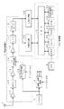
図1は、この実施形態のGPS受信機の構成例を示すブロック図であり、周波数変換部10と、同期捕捉部20と、同期保持部30と、制御部40と、GPSアンテナ1と、温度補償付き水晶発振回路からなる基準発振回路2と、タイミング信号生成回路3と、水晶発振回路4とを備えて構成される。
【0036】
制御部40は、CPU(Central Processing Unit)41に対して、プログラムROM(Read Only Memory)42と、ワークエリア用のRAM(Random Access Memory)43と、実時間(RTC(Real Time Clock))を計測するための時計回路44と、タイマ45と、軌道情報用メモリ46とが接続されて構成されている。
【0037】
タイマ45は、各部の動作に必要な各種タイミング信号の生成および時間参照に使用される。軌道情報用メモリ46は、不揮発性メモリとされ、これにはGPS衛星信号から抽出したアルマナック情報およびエフェメリス情報からなる軌道情報が記憶される。軌道情報用メモリ46に対して、エフェメリス情報は、例えば2時間毎に更新され、また、アルマナック情報は、例えば数日あるいは数ヶ月毎に更新される。
【0038】
基準発振回路2からの基準クロック信号は、逓倍/分周回路3に供給されると共に、後述するように、周波数変換部10の周波数変換用の局部発振回路15に供給される。逓倍/分周回路3は、基準クロック信号を逓倍して、また、分周して、同期捕捉部20、同期保持部30および制御部40などに供給するクロック信号を生成する。逓倍/分周回路3は、制御部40のCPU41により逓倍比や分周比が制御される。
【0039】
なお、水晶発振回路4からのクロック信号は、制御部40の時計回路44用のものとされている。制御部40の時計回路44以外の部位のクロック信号は、逓倍/分周回路3からのクロック信号とされる。
【0040】
[周波数変換部10の構成]
GPS衛星信号は、前述もしたように、各GPS衛星から送信される信号であり、50bpsの送信データを、送信信号速度が1.023MHzで、符号長が1023であって、GPS衛星ごとに決められているパターンのPN符号(拡散符号)によりスペクトラム拡散した信号(C/Aコード)により、周波数が1575.42MHzのキャリア(搬送波)をBPSK変調したものである。
【0041】
アンテナ1にて受信された1575.42MHzのGPS衛星信号は、周波数変換部10に供給される。周波数変換部10では、アンテナ1にて受信されたGPS衛星信号が、低雑音増幅回路11にて増幅された後、バンドパスフィルタ12に供給されて、不要帯域成分が除去される。バンドパスフィルタ12からの信号は、高周波増幅回路13を通じて中間周波変換回路14に供給される。
【0042】
また、基準発振回路2の出力が、PLL(Phase Locked Loop)シンセサイザ方式の局部発振回路15に供給され、この局部発振回路15より基準発振器2の出力周波数に対して周波数比が固定された局部発振出力が得られる。そして、この局部発振出力が中間周波変換回路14に供給されて、GPS衛星信号が、信号処理し易い中間周波数、例えば1.023MHzの中間周波信号に低域変換される。
【0043】
中間周波変換回路14からの中間周波信号は、増幅回路16で増幅され、ローパスフィルタ17で帯域制限された後、A/D変換器18で1ビットのデジタル信号(以下、この信号をIFデータという)に変換される。このIFデータは、同期捕捉部20および同期保持部30に供給される。
【0044】
すなわち、この実施形態では、IFデータは、従来のスライディング相関およびコスタスループ+DLLのような同期捕捉・同期保持一体化回路に供給されるのではなく、機能的に分離された同期捕捉部20と、同期保持部30に供給される。
【0045】
この実施形態において、同期捕捉部20は、GPS衛星信号についての同期捕捉、つまり、GPS衛星信号の拡散符号の位相検出および中間周波信号の周波数(以下、IFキャリア周波数という)の検出を行う。同期保持部30は、同期捕捉部20で捕捉したGPS衛星信号の拡散符号とIFキャリアの同期保持を行う。
【0046】
[同期捕捉部20と同期保持部30の構成]
この実施形態では、後述するように、同期捕捉部20では、周波数変換部10からのIFデータの所定時間分をメモリに取り込み、このメモリに取り込んだIFデータについて、GPS衛星信号の拡散符号と、GPS受信機が持つ個々のGPS衛星の拡散符号に対応する拡散符号との相関演算を行って、拡散符号の位相同期捕捉を行う。
【0047】
拡散符号の位相同期捕捉に関しては、上述のようなスライディング相関の手法を用いることなく、スペクトラム拡散信号の同期捕捉を高速に行う方法として、マッチドフィルタを用いる方法がある。
【0048】
マッチドフィルタは、トランスバーサルフィルタにより、デジタル的に実現可能である。また、近年は、DSP(Digital Signal Processor)に代表されるハードウエアの能力の向上によって、高速フーリエ変換(以下、FFT(Fast Fourier Transform)という)処理を用いたデジタルマッチドフィルタにより、拡散符号の同期を高速に行う手法が実現している。ただし、デジタルマッチドフィルタそのものは、拡散符号の同期を保持する機能を有しない。
【0049】
後者のFFT処理を用いる方法は、古くから知られる相関計算の高速化方法に基づいており、受信機側の拡散符号と、受信信号の拡散符号との間に相関がある場合には、後述する図4に示すような相関のピークが検出され、ピークの位置が拡散符号の先頭の位相である。したがって、この相関のピークを検出することで、拡散符号の同期を捕捉、すなわち、受信信号における拡散符号の位相を検出することができる。
【0050】
受信信号のキャリア(中間周波数)は、FFTを利用した方法で、FFTの周波数領域での操作により、拡散符号の位相とともに検出することができる。拡散符号の位相は、疑似距離に換算され、4個以上の衛星が検出されれば、GPS受信機の位置を計算することができる。また、キャリア周波数が検出されると、ドップラーシフト量が判り、これにより、GPS受信機の速度が計算できる。
【0051】
以上のことから、この実施形態では、高速フーリエ変換(以下、FFT(Fast Fourier Transform)という)処理を用いたデジタルマッチドフィルタにより拡散符号についての相関計算を行い、その相関計算に基づいて同期捕捉処理を高速に行う。
【0052】
アンテナ1で受信されるGPS衛星信号には、複数のGPS衛星からの信号が含まれているが、同期捕捉部20では、すべてのGPS衛星についての拡散符号の情報を用意しており、その用意されている拡散符号の情報を用いて、その時点でGPS受信機が利用可能な複数個のGPS衛星信号の拡散符号との相関を計算することにより、それらの複数個のGPS衛星信号の同期捕捉をすることが可能である。
【0053】
同期捕捉部20では、いずれのGPS衛星用の拡散符号の情報を用いて同期捕捉したかにより、いずれのGPS衛星からの信号の同期捕捉をしたかを検知する。当該同期捕捉したGPS衛星の識別子としては、例えばGPS衛星番号が用いられる。
【0054】
そして、同期捕捉部20は、同期捕捉したGPS衛星の衛星番号の情報と、同期捕捉により検出した拡散符号の位相の情報と、IFキャリア周波数の情報と、また、必要に応じて、相関の度合いを示す相関検出信号からなる信号強度の情報を、同期保持部30に渡すようにする。
【0055】
同期捕捉部20で検出した衛星番号、拡散符号の位相、IFキャリア周波数、信号強度の情報を、同期保持部30へ渡す方法としては、データのフォーマット、割り込みの方法等を決めた上で、同期捕捉部20から同期保持部30へ直接渡す方法と、制御部40を介して渡す方法とがある。
【0056】
前者の場合には、同期捕捉部20のDSP23で、同期保持部30に渡す情報を生成する。あるいは、同期保持部30に、例えばDSPで構成される制御部を設け、その制御部で、同期捕捉部20からの情報に基づいて、同期保持部30で必要な情報を生成する構成とする。
【0057】
また、後者の場合には、制御部40のCPU41が制御し、CPU41を介して情報の受け渡し、またCPU41から同期捕捉部20および同期保持部30の制御を行うことができるので、後述する拡散符号の位相補正や、同期捕捉部20と同期保持部30の状況に応じた多様な同期手順を設定しやすくなる。
【0058】
そこで、以下に説明する実施形態では、同期捕捉部20から、衛星番号、拡散符号の位相、IFキャリア周波数、信号強度の情報を、同期保持部30へ渡す方法としては、制御部40を介して渡す方法を採用している。
【0059】
[同期捕捉部20の構成]
図2は、同期捕捉部20の構成例を示すものであって、この例では、サンプリング回路21と、データバッファ用のRAM(Random Access Memory)22と、DSP(Digital Signal Processor)23と、プログラムROM(Read Only Memory)と、ワークエリア用のRAMとからなるDSP23用のメモリ部24とを備えて構成される。DSP22およびDSP用のメモリ部24とは、制御部40のCPU41に接続されている。
【0060】
サンプリング回路21では、周波数変換部10からの1.023MHzのIFデータを、2倍以上の所定の周波数でサンプリングし、各サンプリング値をRAM22に書き込む。RAM22は、所定時間長分のIFデータを記憶する容量を有する。DSP23では、このRAM22の容量分の時間長のIFデータ単位に同期捕捉処理を行う。
【0061】
すなわち、この例では、DSP23は、RAM22に取り込んだIFデータについて、高速フーリエ変換(以下、FFT(Fast Fourier Transform)という)処理を用いたデジタルマッチドフィルタにより、拡散符号の同期捕捉を高速に行う。そして、DSP23は、その同期捕捉の結果として、同期捕捉したGPS衛星番号と、同期捕捉したGPS衛星信号の拡散符号の位相およびそのIFキャリア周波数とを検出する。
【0062】
サンプリング回路21におけるサンプリング周波数により、拡散符号の位相の検出精度が決まる。このサンプリング周波数は、サンプリング定理からIF信号に含まれる最大周波数の2倍以上である必要があり、IFキャリア周波数の整数倍の周波数が望ましい。
【0063】
また、RAM22の容量により決まるDSP23での処理単位の時間長により、IFキャリア周波数の検出精度が決まる。このDSP23での処理単位の時間長は、拡散符号の1周期の整数倍、後述のように、特に2のべき乗倍が望ましい。
【0064】
ここで、サンプリング回路21でのサンプリング周波数を、拡散符号のチップレートのα倍、RAM22に取り込むIFデータの時間長を拡散符号の1周期のβ倍(βミリ秒)とすると、DSP23では、FFTの周波数領域での操作により、拡散符号の位相は1/αチップの精度で検出することができ、IFキャリア周波数は、1/βkHz(±1/2βkHz)の精度で検出することができる。
【0065】
次に、DSP23におけるFFTを用いたデジタルマッチドフィルタによる同期捕捉のいくつかの例について詳述する。
【0066】
〔デジタルマッチドフィルタによる同期捕捉の第1の例〕
この例においては、サンプリング回路21でのサンプリング周波数は、拡散符号のチップレートのほぼ4倍の4.096MHzとされる。そして、RAM22には、拡散符号の1周期分(1ミリ秒)である4096サンプル点のデータを記憶する。DSP23は、このRAM22に取り込まれた1ミリ秒単位のデータについて、GPS衛星信号の拡散符号とGPS受信機の拡散符号との相関を、FFTを用いた相関演算により計算して、同期捕捉を行う。拡散符号の1周期分は、1023チップであるから、1/4チップの精度で拡散符号の位相検出が可能となる。また、IFキャリア周波数の検出精度は、1ミリ秒単位のFFT処理であるので、1kHzである。
【0067】
この例では、図3に示すように、DSP23では、RAM22に書き込まれた1ミリ秒単位のIFデータを読み出して、FFT処理部101でFFT処理し、そのFFT結果をメモリ102に書き込む。そして、メモリ102から読み出した受信信号のFFT結果は、乗算部103に供給する。
【0068】
一方、拡散符号発生部104から、GPS衛星からの受信信号に使用されている拡散符号と同じ系列と考えられる拡散符号を発生させる。実際的には、拡散符号発生部104からは、予め用意されている複数個のGPS衛星の拡散符号が順次に切り換えられて出力されることになる。
【0069】
この拡散符号発生部104からの1周期分(1023チップ)の拡散符号は、FFT処理部105に供給されてFFT処理され、その処理結果がメモリ106に供給される。このメモリ106からは、通常の場合と同様に、FFT結果が低い周波数から順に読み出されて乗算部103に供給される。
【0070】
乗算部103では、メモリ102からの受信信号のFFT結果と、メモリ106からの拡散符号のFFT結果とが乗算され、周波数領域における受信信号と拡散符号との相関の度合いが演算される。ここで、乗算部105での乗算は、受信信号の離散フーリエ変換結果と、拡散符号の離散フーリエ変換結果とのどちらか一方の複素共役と他方とを乗算する演算となる。そして、その乗算結果は逆FFT処理部107に供給されて、周波数領域の信号が時間領域の信号に戻される。
【0071】
逆FFT処理部107から得られる逆FFT結果は、受信信号と拡散符号との時間領域における相関検出信号となっている。この相関検出信号は、相関点検出部108に供給される。
【0072】
この相関検出信号は、拡散符号の1周期分の各チップ位相における相関値を示すものとなっており、所定の強度以上である受信信号中の拡散符号と、拡散符号発生部104からの拡散符号とが同期している位相(拡散符号の1周期分単位の位相)においては、図4に示すように、1023チップのうちのある一つの位相での相関値が、予め定められるスレッショールド値を超えるようなピーク値を示す相関波形が得られる。このピーク値の立つチップ位相が、相関点の位相であり、GPS受信機側の拡散符号に対するGPS衛星信号の拡散符号の1周期の先頭の位相となる。
【0073】
一方、受信信号が所定の強度以下である場合、受信信号中の拡散符号と、拡散符号発生部104からの拡散符号とが同期しても、図4のようなピーク値が立つ相関波形は得られず、いずれのチップ位相においても、予め定められるスレッショールド値を超えるようなピークは立たない。
【0074】
相関点検出部108は、例えば、予め定めた値を超えるピーク値が、この相関点検出部108に供給される相関検出信号に存在するかどうかにより、受信信号と拡散符号との同期が取れたかどうかを検出する。
【0075】
相関点検出部108で同期が取れたことを検出した場合には、前記ピーク値の位相を相関点、つまり、GPS衛星信号の拡散符号の位相として検出する。そして、DSP23は、そのときの拡散符号発生部104からの拡散符号がいずれのGPS衛星用のものであるかにより、GPS衛星番号を認識する。
【0076】
また、図4に示した相関検出信号は時間領域のものであるが、後述する処理により中間周波受信信号におけるキャリア成分を正しく除去した場合にのみ相関のピークが検出される。
【0077】
そして、除去を行ったキャリア成分の周波数が、前記の予め定めた値を超えるピーク値が立つ相関点に対応する、ドップラーシフト分を含めたIFキャリア周波数となる。したがって、このドップラーシフト分を含めたIFキャリア周波数が、相関点検出の結果としてDSP23において、検出される。
【0078】
以上のようにして、一つのGPS衛星についての同期捕捉が完了すると、この例では、拡散符号発生部104から発生させる拡散符号を他のGPS衛星信号の拡散符号に対応するものに変更して、上記の処理を繰り返す。また、同期が取れなかった場合にも、DSP23では、拡散符号発生部104から発生させる拡散符号を他のGPS衛星信号の拡散符号に対応するものに変更して、上記の処理を繰り返す。
【0079】
そして、DSP23では、サーチすべき全GPS衛星についての同期捕捉処理が終了したとき、あるいは制御部40のCPU41からの情報により、例えば4個以上のGPS衛星についての拡散符号の同期が取れたときに、以上の同期捕捉処理を終了する。
【0080】
DSP23は、その同期捕捉の結果として検出した、同期捕捉したGPS衛星番号と、同期捕捉したGPS衛星信号の拡散符号の位相およびそのIFキャリア周波数とからなる情報を、制御部40に供給する。また、この例では、DSP23は、同期捕捉した各GPS衛星信号についての相関点のピーク値をも、制御部40に供給するようにしている。
【0081】
以上の説明では、受信信号のキャリアの処理を考慮していないが、実際には、受信信号r(n)は、図43の式(3)に示すようにキャリアを含んでいる。この式(3)において、Aは振幅、d(n)はデータ、foは中間周波信号におけるキャリア角周波数、n(n)はノイズを表している。
【0082】
サンプリング部21でのサンプリング周波数をfs 、拡散符号の1周期分についてのサンプリング数をN(したがって、0≦n<N)とすると、離散フーリエ変換後の離散周波数k(0≦k<N)と実周波数fとの関係は、
0≦k≦N/2ではf=k・fs /N、
N/2<k<Nではf=(k−N)・fs /N(f<0)
である。なお、離散フーリエ変換の性質により、R(k)、C(k)は、k<0およびk≧Nでは循環性を示す。
【0083】
そして、受信信号r(n)から、データd(n)を得るためには、拡散符号c(n)とキャリアcos2πnf0との同期をとってキャリア成分を除去する必要がある。すなわち、後述する図43の式(2)で、R(k)のみにキャリア成分が含まれている場合には、図4のような相関波形が得られない。
【0084】
この実施の形態では、FFTによる周波数領域での処理のみの簡単な構成により、拡散符号c(n)とキャリアcos2πnf0との同期をとってキャリア成分を除去することができるようにしている。
【0085】
すなわち、FFT処理部101から得られるGPS衛星からの受信信号のFFT結果は、通常は、受信信号の周波数成分の周波数が低いものから順にメモリ102から読み出されて、乗算部103に供給されるが、この実施の形態では、メモリ102からは、読み出しアドレス制御部109からの制御に従って、読み出しアドレスがシフト制御されて、順次、受信信号のFFT結果が読み出される。
【0086】
読み出しアドレス制御部109には、受信信号を得たGPS衛星についてのドップラーシフト量を正確に見積もり、かつ、GPS受信機内部の発振周波数および時間情報を正確に校正することに基づいて検出した受信信号のキャリア周波数の情報が供給される。このキャリア周波数の情報は、GPS受信機内部でのみ生成することもできるが、外部から取得するようにすることもできる。
【0087】
そして、読み出しアドレス制御部109は、GPS受信機内部で生成した、あるいは外部から取得したキャリア周波数の情報に基づいて、そのキャリア周波数分だけ、読み出しアドレスをシフトして、メモリ102から受信信号のFFT結果を、順次、読み出し、乗算部103に供給するようにする。
【0088】
このように受信信号r(n)のFFT結果を、メモリ102から、受信信号のキャリア周波数分だけシフトして読み出すことにより、後述するように、キャリア成分を除去した受信信号のFFT結果と等価なFFT結果を得ることができ、そのキャリア成分を除去したFFT結果と、拡散符号の1周期分のFFT結果との乗算結果を逆拡散することにより、確実に図4のように相関点でピークを生じる相関検出出力が得られる。
【0089】
なお、後述もするように、メモリ102からのFFT結果の読み出しアドレスを制御するのではなく、メモリ106からの拡散符号のFFT結果の読み出しアドレスを制御することにより、拡散符号のFFT結果に、受信信号r(n)のキャリア分を加え、乗算部103での乗算によって、実質的によりキャリア成分の除去を行うようにすることもできる。
【0090】
以下に、メモリ102または106からの読み出しアドレスの制御によって、受信信号のキャリアと拡散符号との同期によるキャリア成分の除去について、DSP23でのデジタルマッチドフィルタの処理の動作説明と共に、さらに詳細に説明する。
【0091】
この実施の形態において、DSP23では、デジタルマッチドフィルタの処理が行われるものであるが、このデジタルマッチドフィルタの処理の原理は、図43の式(1)に示すように、時間領域での畳み込みのフーリエ変換が周波数領域では乗算になるという定理に基づくものである。
【0092】
この式(1)において、r(n)は時間領域の受信信号、R(k)はその離散フーリエ変換を表す。また、c(n)は拡散符号発生部からの拡散符号、C(k)はその離散フーリエ変換を表す。nは離散時間、kは離散周波数である。そして、F[]は、フーリエ変換を表している。
【0093】
2つの信号r(n)、c(n)の相関関数を改めてf(n)と定義すると、f(n)の離散フーリエ変換F(k)は、図43の式(2)のような関係になる。したがって、r(n)を周波数変換部10からの信号とし、c(n)を拡散符号発生部104からの拡散符号とすれば、r(n)とc(n)の相関関数f(n)は、通常の定義式によらず、前記式(2)により以下の手順で計算できる。
【0094】
・受信信号r(n)の離散フーリエ変換R(k)を計算する。
【0095】
・拡散符号c(n)の離散フーリエ変換C(k)の複素共役を計算する。
【0096】
・R(k)、C(k)の複素共役より、式(2)のF(k)を計算する。
【0097】
・F(k)の逆離散フーリエ変換により相関関数f(n)を計算する。
【0098】
ところで、前述したように、受信信号r(n)に含まれる拡散符号が、拡散符号発生部104からの拡散符号c(n)と一致していれば、上記手順により計算した相関関数f(n)は、図4のように相関点でピークを生ずる時間波形となる。上述したように、この実施の形態では、離散フーリエ変換および逆フーリエ変換に、FFTおよび逆FFTの高速化アルゴリズムを適用したので、定義に基づいて相関を計算するより、かなり高速に計算を行うことができる。
【0099】
次に、受信信号r(n)に含まれるキャリアと拡散符号との同期について説明する。
【0100】
前述したように、受信信号r(n)は、図43の式(3)に示すようにキャリアを含んでいる。受信信号r(n)から、データd(n)を得るためには、拡散符号c(n)とキャリアcos2πnf0との同期をとって除去する必要がある。すなわち、前述の図43の式(2)で、R(k)のみにキャリアが含まれている場合には、図4のような相関波形が得られない。
【0101】
ドップラーシフト量が正確に見積もられ、かつ、GPS受信機内部の発振周波数および時間情報が正確であれば、受信信号r(n)のキャリア周波数f0が既知となる。その場合には、図5に示すように、FFT処理部101の前段に乗算部121を設け、この乗算部121において受信信号r(n)と信号発生部122からの周波数f0のキャリアとを乗算して周波数変換することにより、FFTを行う前に受信信号r(n)からキャリア成分を除くことができる。
【0102】
その場合には、メモリ102からは、そのキャリア成分が除去された受信信号r(n)のFFT結果が得られ、このFFT結果と、拡散符号c(n)のFFT結果とが乗算部103で乗算されるので、逆FFT処理部107の出力としては、図4のように相関点にピークを生じる時間波形が確実に得られる。
【0103】
なお、図5で括弧内に記載したように、受信信号r(n)からキャリア成分を除去するのではなく、拡散符号c(n)についてのFFT処理部105の前段に乗算部121を設けて、この乗算部121において拡散符号c(n)と信号発生部122からの周波数f0のキャリアとを乗算して周波数変換することにより、拡散符号にキャリア成分を加えるようにしても同様である。
【0104】
すなわち、その場合には、メモリ102から読み出した受信信号のFFT結果に含まれるキャリア成分と、メモリ106から読み出した拡散符号のFFT結果に含まれる、加えられたキャリア成分とが同期しているため、逆FFT処理部107からは、図4のように相関点でピークを生じる相関検出出力が得られる。
【0105】
しかし、以上説明したような図5のように時間領域の信号にキャリア周波数の信号を乗算する方法による場合には、キャリア成分を除くための乗算部が特に必要になり、構成が複雑になると共に、その乗算演算の分だけ、処理速度が遅くなるという不利益がある。
【0106】
ところで、FFTの性質として、上述のような周波数乗算は、図43の式(4)のように表すことができる。この式(4)で、F[]は離散フーリエ変換、φ0 はキャリアとの位相差、k0 はf0 に対応するkであって、f0 =k0 ・fs /Nである。この式(4)より、受信信号r(n)を図5のように周波数変換した信号のFFTは、r(n)のFFTであるR(k)を、キャリア周波数分k0だけシフトした形になる。
【0107】
以上のことから、図5の構成は、図6のような構成に置換可能となる。すなわち、受信信号r(n)や拡散符号c(n)にキャリア周波数を乗算する代わりに、受信信号のFFT結果または拡散符号のFFT結果をメモリ102またはメモリ106からの読み出す際の読み出しアドレスを、キャリア周波数分だけシフトするようにするものである。
【0108】
この場合に、図6で、受信信号r(n)をシフトする場合はダウンコンバージョンで、k0 >0とし、また、拡散符号c(n)をシフトする場合はアップコンバージョンで、k0 <0とする。
【0109】
以上説明したように、式(4)に示したFFTの性質を利用すれば、図5の信号発生器122は不要になり、図6のように、FFT結果のメモリからの読み出しアドレス位相をシフトするだけでよくなり、構成が簡単になると共に、処理の高速化につながる。
【0110】
なお、前述の式(4)における位相差φ0 は未知であるため、図6では無視しているが、例えば、図43の式(5)により計算されるF’(k)の逆FFTの演算結果として得られる相関関数f’(n)(0≦n<N)は複素数となり、その実部をfR’(n)、虚部をfI’(n)とすると、相関ピークの振幅|f’(n)|は、図43の式(6)に示すようにして得られ、位相φは、図43の式(7)に示すようにして得られるので、式(4)の右辺のexp(jφ0 )の乗算は省略してよい。なお、位相φ は、式(3)のデータd(n)の符号に対応したπだけ異なる2つの値に式(7)のφ0が加わった値となる。
【0111】
以上説明したような、DSP23における同期捕捉処理の第1の例の動作を図3のブロック図に反映させた構成図を図7に示す。この図7の各ブロックの出力には、上述したような信号出力r(n)、c(n)および演算結果R(k)、C(k)、f'(n)が示されている。
【0112】
以上のように、DSP23での捕捉処理の第1の例によれば、GPS受信機において、FFTを利用してデジタルマッチドフィルタを構成する場合に、図7のように受信信号のFFT結果を、キャリア周波数分だけメモリのアドレスをシフトして、拡散符号と乗算する構成によって、相関点np が、例えば図7に示すような波形で得られ、4個のGPS衛星、つまり4種類の拡散符号c(n)について、相関点np が判れば、GPS受信機位置の計算が可能になる。
【0113】
すなわち、第1の例によれば、FFTを利用したデジタルマッチドフィルタ処理を行う場合において、受信信号のキャリアと拡散符号との同期を取るために、時間領域で乗算を行うことなく、受信信号のFFT結果と拡散符号のFFT結果同士の周波数領域での乗算の際に、受信信号のFFT結果と拡散符号のFFT結果のうちの一方のFFT結果をシフトするという簡便な方法により、受信信号のキャリア成分を除去することができる。
【0114】
なお、図7の例では、受信信号のFFT結果R(k)の方の、メモリの読み出しアドレスをシフトさせたが、拡散符号のFFT結果C(k)の方のメモリの読み出しアドレスを、受信信号のFFT結果R(k)の場合とは逆方向にシフト(乗算器でのアップコンバージョンの形になる)しても良い。
【0115】
また、上述の第1の例の説明においては、拡散符号発生器104とFFT処理部105とを別々に設けるようにしたが、それぞれのGPS衛星に対応する拡散符号を予めFFTしておいたものをメモリに記憶させておくことで、衛星信号の受信時における拡散符号c(n)のFFT計算を省略することができる。
【0116】
〔デジタルマッチドフィルタによる同期捕捉の第2の例〕
上述の同期捕捉の第1の例は、GPS衛星からの受信信号のキャリア周波数が既知である場合であったが、この同期捕捉の第2の例は、キャリア周波数が未知である場合である。第1の例と同様に、この第2の例においては、サンプリング回路21でのサンプリング周波数は、4.096MHzであり、RAM22の容量は、サンプリング回路21からのデータの1ミリ秒分の容量である。
【0117】
図8は、第2の例としてのDSP23の構成例を示すブロック図である。この図8において、前述した第1の例として示した図3のDSP23の構成例と同一部分には、同一番号を付してある。
【0118】
この同期捕捉の第2の例では、図8に示すように、相関点検出部108の相関検出出力を、読み出しアドレス制御部110に供給する。読み出しアドレス制御部110は、受信信号r(n)のFFT結果のメモリ102からの読み出しアドレスの前記シフト量を、過去のデータから決定した予測アドレスを中心に、相関点検出部108の相関検出出力に基づいて変更制御して、相関点検出部108で図4に示したようなピークが得られるようにする。相関点検出部108で図4に示したようなピークが得られたときには、読み出しアドレス制御部110は、読み出しアドレスのシフト制御を、そのときのシフト量で停止する。
【0119】
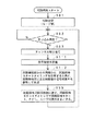
この同期捕捉の第2の例における同期捕捉部20での処理の流れを、図9および図10のフローチャートを参照しながら説明する。なお、この図9および図10のフローチャートは、主としてDSP23でのソフトウエア処理に対応するものである。
【0120】
まず、周波数変換部10からのIFデータをサンプリング回路21でサンプリングし、信号r(n)としてRAM22に取り込む(ステップS1)。次に、この信号r(n)をFFT処理部101でFFTし、そのFFT結果R(k)をメモリ102に書き込む(ステップS2)。次に、信号を受信したGPS衛星に対応する拡散符号のFFT結果C(k)をメモリ106にセットする(ステップS3)。
【0121】
次に、受信信号r(n)のFFT結果R(k)のメモリ102からの読み出しアドレスのシフト量の初期値k0’を、過去のデータから決定する(ステップS4)。そして、決定した初期値k0’を、メモリ102からのFFT結果の読み出しアドレスのシフト量k'として設定すると共に、シフト制御の変更回数vを初期値v=0にセットする(ステップS5)。
【0122】
次に、メモリ102から、受信信号r(n)のFFT結果R(k)を、読み出しアドレスを、k'だけシフトして読み出す(ステップS6)。そして、読み出したFFT結果R(k−k')と、拡散符号のFFT結果C(k)の複素共役とを乗算して相関関数F’(k)を求める(ステップS7)。
【0123】
次に、この相関関数F’(k)の逆FFTを行って時間領域の関数f’(n)を求める(ステップS8)。そして、この関数f’(n)について、ピーク値f’(np)を求め(ステップS9)、そのピーク値f’(np)が予め設定されているスレッショールド値fthより大きいかどうか判別する(図10のステップS11)。
【0124】
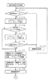
ステップS11での判別の結果、ピーク値f’(np)が、予め設定されているスレッショールド値fthより小さいときには、相関点が検出できなかったとして、シフト制御の変更回数vが予め設定された最大値vmaxよりも小さいかどうか判別する(ステップS16)。この最大値vmaxは、周波数に換算したときに、1kHzに相当する。
【0125】
そして、シフト制御の変更回数vが予め設定された前記最大値vmaxよりも小さいと判別したときには、シフト制御の変更回数vを1だけインクリメント(v=v+1)すると共に、新たなシフト量k'を、
k'=k'+(−1)v×v
として設定し(ステップS17)、その後、ステップS6に戻る。そして、上述したステップS6以降の処理を繰り返す。
【0126】
また、ステップS16で、シフト制御の変更回数vが、予め設定された前記最大値vmaxよりも大きいと判別したときには、そのように大きいと判別された回数が、現在のRAM22のデータに対して予め定められた所定回数以上となったか否か判別し(ステップS18)、前記所定回数以上でなければ、ステップS1に戻り、RAM22に新たなデータを取り込んで、以上の処理を繰り返す。
【0127】
また、ステップS18で、前記所定回数以上であると判別したときには、サーチすべきすべての衛星について、上述の拡散符号同期サーチ処理が終了したか否か判別し(ステップS14)、すべての衛星についての拡散符号同期サーチ処理が終了したと判別したときには、サーチ動作を終了する(ステップS19)。
【0128】
また、ステップS14で、拡散符号同期サーチが終了していないサーチすべき衛星があると判別したときには、次に拡散符号同期サーチを行う衛星を選択し、その選択した衛星が用いる拡散符号c(n)に拡散符号を変更する(ステップS15)。そして、ステップS3に戻り、上述したステップS3以降の処理を実行する。
【0129】
また、ステップS11において、ピーク値f’(np)が、予め設定されているスレッショールド値fthより大きいと判別したときには、そのピーク値f’(np)を取る離散時間(拡散符号の位相)npを相関点として検出する(ステップS12)。
【0130】
そして、検出した相関点npが、4個目であるか否か判別し(ステップS13)、4個目であると判別したときには、受信機位置計算処理を開始し、同期保持部30における同期保持処理をする(ステップS20)。その後、ステップS14に移行する。ステップS20の処理は、4個目以降でも行うにようにしてもよい。
【0131】
なお、ステップS12で検出した相関点npが得られるときの読み出しアドレスシフト量k'から、当該受信中のGPS衛星についてのドップラーシフト量およびGPS受信機の発振周波数の誤差を推定することができる。すなわち、受信信号のキャリア周波数を検知することができる。
【0132】
ステップS13で、検出した相関点npが、4個目以外であると判別したときには、サーチすべきすべての衛星について、上述の拡散符号同期サーチ処理が終了したか否か判別し(ステップS14)、サーチすべきすべての衛星についての拡散符号同期サーチ処理が終了したと判別したときには、サーチ動作を終了する(ステップS19)。
【0133】
また、ステップS14で、拡散符号同期サーチが終了していない衛星があると判別したときには、次に拡散符号同期サーチを行う衛星を選択し、その選択した衛星が用いる拡散符号c(n)に拡散符号を変更する(ステップS15)。そして、ステップS3に戻り、上述したステップS3以降の処理を実行する。
【0134】
以上説明したような同期捕捉の第2の例の処理動作を、図8のDSP23の内部構成のブロック図に反映させた構成図を図11に示す。この図11の各ブロックの出力には、上述したような信号出力および演算結果が示されている。
【0135】
以上のようにして、同期捕捉の第2の例によれば、GPS衛星からの受信信号のキャリア周波数が未知であっても、FFTによる周波数領域での処理を積極的に用いて、受信信号のキャリアと拡散符号との同期検出を行って、キャリア成分を除去することができる。したがって、FFTを利用したデジタルマッチドフィルタによるGPS受信信号と拡散符号との相関点の検出を、高速、かつ簡単な構成で実現することができる。そして、メモリ102の読み出しアドレスのシフト量から、IFキャリア周波数を検出することができる。
【0136】
なお、この第2の例の場合においても、それぞれの衛星に対応する拡散符号を予めFFTしておいたものをメモリに記憶させておくことで、衛星信号の受信時における拡散符号c(n)のFFT計算を省略することができる。
【0137】
〔デジタルマッチドフィルタによる同期捕捉の第3の例〕
上述したように、デジタルマッチドフィルタによって受信信号と拡散符号の相関点を検出する場合には、その相関点を検出する単位データ長は、拡散符号の1周期長とするのが通常である。
【0138】
しかし、GPS衛星からの受信信号では、前述したように、データの1ビットは、拡散符号の20周期分であり、この20周期分では、すべて同じパターンの符号となっている。この同期捕捉の第3の例では、この特質を生かして、デジタルマッチドフィルタによって受信信号と拡散符号の相関点を検出する単位データ長は、拡散符号の複数周期長とする。サンプリング回路21におけるサンプリング周波数は、前述の例と同様でよい。
【0139】
受信信号について、拡散符号の複数周期分単位でFFT演算処理をすることにより、この第3の例によれば、IFキャリア周波数の検出精度が高くなると共に、受信感度が向上し、同じ時間領域の信号を累積加算する方法に比べて、拡散符号の同期捕捉およびIFキャリア周波数のサーチがし易くなる。以下、この同期捕捉の第3の例を、さらに説明する。
【0140】
時間領域において、拡散符号のM周期(Mは2以上の整数)に渡って累積加算を行った1周期長のデータに対して相関点を検出する先行例がある(例えば米国特許4998111号明細書または「An Introduction to Snap TrackTM Server−Aided GPS Technology, ION GPS−98 Proceedings」参照)。
【0141】
すなわち、図12に示すように、この先行例の方法においては、受信信号r(n)について、拡散符号との乗算結果を、M周期分に渡って累積加算するものである。この先行例の方法は、GPS衛星からの受信信号の周期性とノイズの統計的な性質とを利用してC/Nを高めるもので、受信信号のキャリアと拡散符号の同期が事前にとれている状態であれば、C/NがM倍に改善され、したがって受信感度(相関点の検出感度)はM倍に向上する。そして、キャリア周波数の検出精度のM倍に向上する。
【0142】
しかし、受信信号のキャリアと拡散符号との同期がとれていないと位相の異なるM個のキャリアが加算合成されてしまい、累積加算した結果においては肝心のGPS信号が相殺されてしまって相関ピークは検出できなくなる。
【0143】
このため、受信信号のキャリア周波数が未知の場合には、キャリア周波数をサーチする必要があり、サーチする各々の周波数毎に累計加算を行うといった効率の悪い操作を行わざるを得なくなる。
【0144】
これに対して、上述した同期捕捉の第1および第2の例では、上述したようにして周波数領域において、FFT結果のメモリからの読み出しアドレスをシフトするという簡便な方法により、受信信号のキャリアと拡散符号との同期がとれるので、累積加算の効果を最大限に発揮させることができる。
【0145】
この同期捕捉の第3の例では、第2の例と同様に、GPS衛星からの受信信号のキャリア周波数は未知として、キャリア周波数のサーチを行うのであるが、その場合に、受信信号r(n)については、拡散符号のM周期分毎にFFTを行うようにする。そして、この拡散符号のM周期分毎に、受信信号のFFT結果のメモリからの読み出しアドレスのシフト量の制御による受信信号のキャリア周波数のサーチを行う。
【0146】
前述した図43の式(3)中のデータd(n)は、M≦20とすれば、拡散符号のM周期中では1または−1の固定値になるので無視できる。すると、式(3)は、
r(n)=A・c(n)cos2πnf0 +n(n)
となり、これをM周期長で離散フーリエ変換すると、データの数はM×N(Nは拡散符号の1周期分のデータ数)なので、離散フーリエ変換後のkと実周波数fの関係は、サンプリング周波数fs に対して
0≦k≦MN/2では、f=kfs /MN
となり、
MN/2<k<MNでは、f=(k−MN)fs /MN(ただしf<0)
となって、分解能がM倍になる。
【0147】
しかし、拡散符号c(n)は周期信号であり、その1周期長の時間をT(GPSのC/AコードではT=1ミリ秒)とすると、f=1/T以下の精度の周波数成分はない。したがって、受信信号r(n)の離散フーリエ変換後のFFT結果R(k)(ただし、0≦k<MN)中の拡散符号c(n)の周波数成分はM個おき、すなわち、MN個のデータのうちのN個の点に集中し、その振幅は、M周期分が累積加算されるため、1周期長での同じ周波数成分のM倍になる。説明の簡単のため、M=4としたときのスペクトラム例を図13に示す。
【0148】
図13の例では、信号のスペクトラムがM=4個おきにあり、それらの間には信号成分はない。N個の点以外では、拡散符号c(n)の周波数成分は0になる。一方、ノイズn(n)は、多くの場合、非周期信号であるから、MN個の全周波数成分にエネルギーが分散される。したがって、受信信号r(n)のFFT結果R(k)中における拡散符号c(n)のN個の周波数成分の総和において、時間領域での累積加算と同様に、C/NがM倍向上することになる。
【0149】
受信信号r(n)中に、式(3)に示したキャリア成分cos2πnf0がなければ、FFT結果R(k)中の拡散符号c(n)の周波数成分は、k=i×M(ただし、0≦i<N)に集中するが、キャリア成分が存在するので、この第3の例では、メモリからのFFT結果R(k)の読み出しアドレスを、拡散符号の1周期当たりについて、k=(i×M)−k0 として、キャリア周波数分のk0 だけ循環的にシフトするようにする。
【0150】
以上説明した第3の例のDSP23の構成は、図8に示した第2の例の場合と同様となるが、RAM22の容量は、拡散符号のM周期分、例えば16周期分(16ミリ秒)とされ、DSP23では、この拡散符号のM周期分のデータ単位で、捕捉処理動作を行う。上述の捕捉処理動作を、DSP23の内部構成に反映させた構成図を図14に示す。
【0151】
すなわち、FFT処理部101からは、FFT演算処理単位を拡散符号のM周期とするFFT結果R(K)が得られ、メモリ104に書き込まれる。この図14では、0≦k<N、0≦K<MNとしている。
【0152】
そして、このメモリ102から、読み出しアドレスがシフト制御されてFFT結果が読み出されて乗算部103に供給され、メモリ106からの拡散符号c(n)のFFT結果C(k)の複素共役と乗算される。
【0153】
この第3の例の場合、この乗算部103から得られる相関関数F(k)は、図43の式(8)に示すようなものとなるようにされる。なお、式(8)で、kは、拡散符号のFFT結果C(k)の複素共役におけるkであり、k0 については、f0 =k0 ・fs /MNである。
【0154】
このとき、図14において、逆FFT処理部107から得られる相関関数f’(n)のピークは、R(K)がM周期の拡散符号を含むので、0≦n<MNの範囲においてM個現れることになる。しかし、相関点の検出は、拡散符号の1周期についての1個でよいので、逆FFT処理部107での計算は、前述の第1および第2の実施の形態の場合と同様に、0≦n<Nの範囲だけで済み、N≦n<MNにおける計算は必要ない。
【0155】
以上のようにして、この第3の例によれば、受信信号r(n)のFFTを拡散符号の1周期のM倍とすることにより、相関点の検出感度、したがって、受信感度を向上させることができる。この場合に、Mが大きいほど、受信感度が高くなるものである。したがって、Mの値を制御することにより、受信感度を制御することが可能になる。
【0156】
なお、この第3の例の場合においても、それぞれの衛星に対応する拡散符号をあらかじめFFTしておいたものをメモリに記憶させておくことで、衛星信号の受信時における拡散符号c(n)のFFT計算を省略することができる。
【0157】
〔デジタルマッチドフィルタによる同期捕捉の第4の例〕
前述の第3の実施の形態では、拡散符号のM周期(M>1)分を含む受信信号r(n)をFFT処理することで、未知のキャリア周波数のサーチを可能にすると共に、受信感度の向上を図ることができるものであるが、データサンプルの数が、拡散符号1周期分の場合のN個からM倍のMN個になるため、FFTの計算時間が長くなると共に、メモリ102の容量が大きくなる。同期捕捉の第4の例は、この問題を改善したものである。
【0158】
図13に示したように、拡散符号のM周期(M>1)をFFT処理単位とした場合のFFT結果R(K)中の周波数成分はM個おきにしか存在しないので、それらのM個おきの周波数成分の間の成分は不要である。
【0159】
ここで、FFT結果R(K)(ただし、0≦K<NM)を、R(i×M)、R(i×M+1)、R(i×M+2)、・・・、R(i×M+M−1)(0≦i<N)のM組に分ける。説明の簡単のため、M=4組に分けた場合の、それぞれの組の分割スペクトラムの例を図15〜図18に示す。キャリア周波数は未知であるが、M組のうちの1組に、相関を検出する対象となるGPS信号のエネルギーがある。図15〜図18の例では、図15のR(i×M)の組に、受信信号r(n)の周波数成分が含まれ、それ以外の3つの分割スペクトラムにはノイズしかない状態を表している。
【0160】
なお、実際の信号ではキャリア周波数k0は、正確にはk'=k0でないため、例えばk0がk0’とk0’+1との間、つまり、k0’≦K<k0’+1であったとすると、k'=k0’と、k'=k0’+1との両方で相関が検出され、k0に近い方が大きな相関を示す。
【0161】
FFT結果R(K)を前記のようにM組に分割した場合、Mが2のべき乗であれば、FFT計算手順の性質から、各組は、それぞれ独立に計算できる。
【0162】
図19は、8個のデータg(0)〜g(7)のFFT計算の信号の流れ図である。図19のFFT結果G(K)を、4個おきのデータに分けるとすると、(G(0),G(4))、(G(1),G(5))、(G(2),G(6))、(G(3),G(7))の4組となる。この中の(G(0),G(4))に注目すると、図20に示す部分だけの計算でよいことが判る。そして、この計算の構造は、他の組(G(1),G(5))、(G(2),G(6))、(G(3),G(7))においても同様となるものである。
【0163】
この4組のデータを1組ずつ調べることにすると、まず、(G(0),G(4))を計算し、調べ終わったら(G(0),G(4))を格納したメモリを開放して次の組に進む。(G(1),G(5))、(G(2),G(6))、(G(3),G(7))と、順次計算して調べ終わったらメモリを開放するという操作を行うことにより、メモリは、G(0)〜G(7)を一括してFFTを求めるのに比べて、1/4のメモリ容量でよくなる。乗算回数は、M個に分割して計算した場合と全体を一括してFFT計算をした場合とでは同じになる。
【0164】
上記の例と同様のことが、Mを2のべき乗にすることで、R(i×M)、R(i×M+1)、R(i×M+2)、・・・、R(i×M+M−1)に適用でき、FFT結果を格納するメモリの容量は、MNの1/M、すなわち、Nで済む。また、R(i×M)、R(i×M+1)、R(i×M+2)、・・・、R(i×M+M−1)の順で相関を検出する際に、途中の組で相関点が検出できてしまえば、残る組については調べる必要がなくなるので、拡散符号のM周期毎の受信信号を一括してFFT処理して検出するより、処理時間が短くなると期待できる。
【0165】
以上説明した同期捕捉の第4の例における同期捕捉部20での処理の流れを、図21および図22のフローチャートを参照しながら説明する。図21および図22の例ではFFTの回数を最小にするため、キャリア周波数のサーチを、各FFTの組毎に、対象とする衛星すべてについて相関検出を行うようにしている。なお、この図21および図22のフローチャートは、主としてDSP23でのソフトウエア処理に対応するものである。
【0166】
まず、R(K)(ただし、0≦K<NMであり、K=i×M+u)の分割組数についての変数u(0≦u<M)を初期化し(ステップS21)、次に、周波数変換部10からのIFデータをサンプリング回路21でサンプリングし、そのサンプリングデータを、拡散符号のM周期分、例えば16周期分(16ミリ秒)、信号r(n)(ただし、0≦n≦MN)としてRAM22に取り込む(ステップS22)。次に、この信号r(n)をFFT処理部101でFFTし、そのFFT結果R(K)をメモリ102に書き込む(ステップS23)。次に、信号を受信したGPS衛星に対応する拡散符号のFFT結果C(k)をメモリ106にセットする(ステップS24)。
【0167】
次に、受信信号r(n)のFFT結果R(K)のメモリ102からの読み出しアドレスのシフト量の初期値k0’を、例えば過去のデータから決定する(ステップS25)。そして、決定した初期値k0’を、メモリ102からのFFT結果の読み出しアドレスのシフト量k'として設定すると共に、シフト制御の変更回数vを、初期値v=0にセットする(ステップS26)。
【0168】
次に、メモリ102から、受信信号r(n)のFFT結果R(K)を、その読み出しアドレスを、k'だけシフトして読み出す(ステップS27)。そして、読み出したFFT結果R(K−k')と、拡散符号のFFT結果C(k)の複素共役とを乗算して相関関数F’(k)を求める(ステップS28)。
【0169】
次に、この相関関数F’(k)の逆FFTを行って時間領域の関数f’(n)を求める(ステップS29)。そして、この関数f’(n)について、ピーク値f’(np)を求め(ステップS30)、そのピーク値f’(np)が予め設定されているスレッショールド値fthより大きいかどうか判別する(ステップS31)。
【0170】
ステップS31での判別の結果、ピーク値f’(np)が、予め設定されているスレッショールド値fthより小さいときには、相関点が検出できなかったとして、シフト制御の変更回数vが予め設定された最大値vmaxよりも小さいかどうか判別する(ステップS32)。この最大値vmaxは、周波数に換算したときに、1kHzに相当する。
【0171】
そして、シフト制御の変更回数vが予め設定された最大値vmaxよりも小さいと判別したときには、シフト制御の変更回数vを1だけインクリメント(v=v+1)すると共に、新たなシフト量k'を、
k'=k'+(−1)v×v
として(ステップS33)、ステップS27に戻る。そして、上述したステップS27以降の処理を繰り返す。
【0172】
また、ステップS32で、シフト制御の変更回数vが、予め設定された最大値mmaxよりも大きいと判別したときには、そのように大きいと判別された回数が、現在のRAM22のデータに対して予め定められた所定回数以上となったか否か判別し(ステップS41)、前記所定回数以上でなければ、ステップS22に戻り、RAM22に新たなデータを取り込んで、以上の処理を繰り返す。
【0173】
また、ステップS41で、前記所定回数以上であると判別したときには、すべての衛星について、上述の拡散符号同期サーチ処理が終了したか否か判別し(ステップS36)、すべての衛星についての拡散符号同期サーチ処理が終了したと判別したときには、変数uがその最大値Mより小さいかどうか判別し(ステップS38)、小さいときには、変数uをインクリメントし(ステップS39)、その後、ステップS23に戻り、このステップS23以降の処理を繰り返す。
【0174】
また、ステップS38で、変数uが最大値Mに等しいあるいは最大値Mより大きいと判別したときには、サーチ動作を終了する(ステップS40)。
【0175】
また、ステップS36で、拡散符号同期サーチが終了していない衛星があると判別したときには、次に拡散符号同期サーチを行う衛星を選択し、その選択した衛星が用いる拡散符号c(n)に拡散符号を変更する(ステップS37)。そして、ステップS24に戻り、上述したステップS24以降の処理を実行する。
【0176】
また、ステップS31において、ピーク値f’(np)が、予め設定されているスレッショールド値fthより大きいと判別したときには、そのピーク値f’(np)を取る離散時間(拡散符号の位相)npを相関点として検出する(ステップS34)。
【0177】
そして、検出した相関点npが、4個目であるか否か判別し(ステップS35)、4個目であると判別したときには、CPU41は、受信機位置計算処理を開始し、同期保持部30における同期保持処理をする(ステップS42)。その後、ステップS36に進む。ステップS42の処理は、4個目以降でも行うにようにしてもよい。
【0178】
なお、ステップS34で検出した相関点npが得られるときのシフト量k'とR(k)の分割組数についての変数uから、当該受信中のGPS衛星についてのドップラーシフト量およびGPS受信機の発振周波数の誤差が推定することができる。
【0179】
ステップS35で、検出した相関点npが、4個目以外であると判別したときには、ステップS36に進み、上述したステップS36以降の処理を実行する。
【0180】
なお、前述した同期捕捉の第1の例の場合のように、キャリア周波数が既知である場合には、R(i×M)、R(i×M+1)、R(i×M+2)、・・・、R(i×M+M−1)の中で該当するものだけを計算すれば、拡散符号の多周期分を含む時間分を単位として受信信号をFFTする方法は、同様に適用できる。
【0181】
〔デジタルマッチドフィルタによる同期捕捉の第5の例〕
前述した同期捕捉の第3の例、第4の例の場合には、拡散符号のM周期分をRAM22に取り込み、当該M周期分のデータをDSP23が読み込んで、上述のようなFFT処理を行って、同期捕捉処理をするようにしている。このため、DSP23での処理データ量が多く、計算量が多くなり、処理速度が遅くなるおそれがある。
【0182】
この同期捕捉の第5の例は、第3の例において説明したように、拡散符号のM周期分、例えば16周期分(16ミリ秒)のIFデータをRAM22に取り込み、当該M周期分のデータ単位で、FFT演算を伴なう同期捕捉処理を行うものであるが、FFT処理部101でFFT処理を行う前に、データサンプル数を低減する前処理を行って、処理の高速化を図るものである。なお、サンプリング回路21でのサンプリング周波数は、例えば4.096MHzとされる。
【0183】
図23は、この第5の例におけるDSP23の構成例を示すものであり、この第5の例においては、FFT処理部101の前に、前処理部130を設ける。その他の構成は、前述の例と同様である。
【0184】
前処理部130は、RAMを備え、そのメモリ容量は、拡散符号の1周期分とされる。すなわち、この第5の例においては、RAM22に取り込まれたM周期分のデータは、同じ拡散符号の1周期分のデータが、M回繰り返されるものに等しく、同期捕捉の第3の例において説明したように、周波数成分としては、拡散符号の1周期分のデータが備えるものしか存在しないことから、前処理部130においては、前記拡散符号のM周期分のデータ量から、拡散符号の1周期分のデータ量に減らす処理を行う。
【0185】
この第5の例においては、その前処理として、M周期分のデータd(n)(0≦n<L、Lは拡散符号のM周期分の全データ数)の離散フーリエ変換の部分集合(S[0]、S[1]・・・S[N−1](ただし、Nは拡散符号の1周期分のサンプリングデータ数))を計算するアルゴリズムを行う。ここで、部分集合S[k](kは離散フーリエ変換後の離散周波数で、0≦k<N)は、次のように定義できる。
【0186】
S[k]=D[k×M+r]
ただし、Dはデータdの離散フーリエ変換、
M=L/N、
rはドップラー周波数による定数、0≦r<M。
【0187】
図24は、前処理部130で行われるアルゴリズムを実行するためのフローチャートである。
【0188】
まず、変数kの初期化(k=0)を行い(ステップS51)、次に、部分集合S[k]を初期化するために、S[k]=0とする(ステップS52)。そして、繰り返しの変数t(0≦t<M)を初期化(t=0)する(ステップS53)。次に、次の(式Q1)を計算する(ステップS54)。
【0189】
S[k]=S[k]old+d[t×N+k]×exp(2πj・r・t/M)・・・(式Q1)
この(式Q1)の処理は、変数tの値が「1」だけ前の値S[k]oldに、現在の変数tの値についての次の項
d[t×N+k]×exp(2πj・r・t/M)
を加算する演算である。
【0190】
データd(n)は、A/D変換器18からの1ビットのIFデジタルデータをサンプリングしたデータであるので、d[t×N+k]は+1または−1となる。そのため、(式Q1)の演算は、一つの足し算または引き算になる。
【0191】
また、exp(2πj・r・t/M)においては、変数はtのみであり、tは、0からM−1の値しかとらないので、この項exp(2πj・r・t/M)の値を、M点のテーブルとして記憶しておき、そのテーブルを用いることにより、この項exp(2πj・r・t/M)をtの変更の度に毎回計算しなくてもよくなり、計算を早くすることができる。
【0192】
ステップS54の(式Q1)の計算が終了したら、変数tを「1」だけインクリメントする(ステップS55)。そして、変数tがMより小さいか否か判別し(ステップS56)、変数tがMより小さいときには、ステップS54に戻って、前記(式Q1)の計算を繰り返す。変数tがM以上のときには、次の(式Q2)を計算する(ステップS57)。
【0193】
S[k]=S[k]old×exp(2πj・r・k/L)・・・(式Q2)
この(式Q2)の処理は、変数kの値が「1」だけ前の値S[k]oldに、現在の変数kの値についての次の項
exp(2πj・r・k/L)
を乗算する演算である。
【0194】
ステップS57の(式Q2)の計算が終了したら、求めたS[k]の値を前処理部130が備えるメモリに書き込む(ステップS58)。次に、変数kを「1」だけインクリメントする(ステップS59)。そして、変数kがNより小さいか否か判別し(ステップS60)、変数kがNより小さいときには、ステップS52に戻って、以上の計算処理を繰り返す。変数kがN以上のときには、前処理を終了して、高速フーリエ変換処理を開始する。
【0195】
以上の前処理により、FFTの対象となるのは、拡散符号のM周期分の全データ数のL点から、拡散符号の1周期分のN点に減るので、FFT演算を高速にすることができる。
【0196】
〔デジタルマッチドフィルタによる同期捕捉の第6の例〕
この同期捕捉の第6の例は、第5の例と同様に、DSP23において、FFT処理部101でFFT処理を行う前に、データサンプル数を低減する前処理を行って、処理の高速化を図るものである。
【0197】
この第6の例の場合におけるDSP23の構成例は、前述した第5の例の場合の図23に示したものと同じである。ただし、第6の例では、前処理部130で行う前処理の内容が第5の例とは異なる。
【0198】
この第6の例も、RAM22に取り込まれたM周期分のデータは、同じ拡散符号の1周期分のデータが、M回繰り返されるものに等しく、同期捕捉の第3の例において説明したように、周波数成分としては、拡散符号の1周期分のデータが備えるものしか存在しないことから、前処理部130においては、前記拡散符号のM周期分のデータ量から、拡散符号の1周期分のデータ量に減らす処理を行う。
【0199】
図25は、この第6の例の前処理を説明するための図である。図25の例においては、サンプリング回路21でのサンプリング周波数は、4.096MHzであり、また、M=16、つまり、16ミリ秒単位でRAM22にデータを取り込んで、FFT処理をする場合である。
【0200】
図25に示すように、この例において、RAM22に記憶するIFデータは、拡散符号の1周期分の16個のデータ群d1(n)、d2(n)、d3(n)、・・・、d16(n)からなる。そして、この例の場合、データ群d1(n)、d2(n)、d3(n)、・・・、d16(n)のそれぞれは、4096点のポイントからなり、16ミリ秒分のデータ全体では、65536点のポイントからなる。
【0201】
そして、16個のデータ群d1(n)、d2(n)、d3(n)、・・・、d16(n)のそれぞれの先頭から、同じポイント位置の値は、GPS衛星信号の場合には、拡散符号の同じ成分を有しているはずである。しかも、前述したように、各ポイントのデータは、1ビットである。
【0202】
以上のことを考慮して、この第6の例の場合には、前処理部130に備えるメモリ130MEMとして、1ワードが16ビットで、4096ワード分の容量を有するメモリを用いる。
【0203】
そして、16個の拡散符号1周期分のデータ群d1(n)、d2(n)、d3(n)、・・・、d16(n)のそれぞれの先頭から、同じポイント位置のデータは、1ワードを構成するように、メモリ130MEMの同じワードアドレスに書き込むようにする。この結果、16ミリ秒分のデータは、メモリ130MEMに、4096ワードのデータとして取り込まれる。
【0204】
FFT演算処理は、この16ビット1ワードのデータについて実行するようにする。DSP23が、16ビット単位の処理が可能であるものであった場合には、FFTの際のメモリアクセス回数は、4096回となり、前処理を行わない場合の65536回に比較して、16分の1にすることができ、FFT処理を高速化することができる。
【0205】
上述のことを、一般化すると、拡散符号の1周期分のデータ数がNであるデータのM周期分を処理単位としてFFT処理する場合において、前処理部130では、同じ拡散符号の成分となる位置のデータを、メモリ130MEMの同じワードアドレスに書き込むようにする。
【0206】
すなわち、NM個のデータを[0]から順に番号をつけたとき、0,N,2N,・・・,(M−1)N番目のデータは、メモリMEMのワードアドレス「0」に書き込み、1,1+N,1+2N,・・・,1+(M−1)N番目のデータは、メモリMEMのワードアドレス「1」に書き込み、・・・・、(N−1),(N−1)+N,(N−1)+2N,・・・,(N−1)+(M−1)N番目のデータは、メモリMEMのワードアドレス「N−1」に書き込むようにするものである。
【0207】
FFT演算処理は、このMビット1ワードのデータについて実行するようにする。DSP23が、wビット単位の処理が可能であるものであった場合には、FFTの際のメモリアクセス回数は、N×M/w回となり、前処理を行わない場合のNM回に比較して、w分の1にすることができ、FFT処理を高速化することができる。
【0208】
以上説明した第1〜第6の例の同期捕捉方法は、従来の手法であるスライディング相関器が原理的に時間を要するのに対し、FFTを用いたデジタルマッチドフィルタによる処理を高速なDSPで行うようにしたことにより、処理時間の大幅な短縮が期待できる。特に、第3の例〜第6の例の場合には、拡散符号のM周期単位でFFT処理をするようにしたことにより、同期捕捉を高感度で行うことができる。
【0209】
さらに、第4の例〜第6の例の場合には、拡散符号のM周期単位でFFT処理を、より高速に行うようにすることができる。
【0210】
なお、以上の同期捕捉の例に用いたデジタルマッチドフィルタによる相関計算の方法は、GPS衛星からの信号に限らず、拡散符号でデータをスペクトラム拡散した信号により搬送波が変調されている受信信号の拡散符号およびキャリアの同期捕捉を行う場合に適用可能である。ただし、第3の例、第4の例、第5の例および第6の例は、GPS衛星信号のように、拡散符号の1周期の複数倍の周期がデータビットとなっていて、拡散符号の複数周期分の信号は、同じ信号となっている必要がある。
【0211】
以上のような同期捕捉方法によって、同期捕捉部20で4個以上のGPS衛星からの信号の同期捕捉ができれば、GPS受信機としては、それらの拡散符号の位相とIFキャリア周波数とからGPS受信機の位置と速度を計算することが可能である。つまり、同期保持部30を設けなくても測位演算を行うことは可能である。
【0212】
しかし、GPS受信機として十分な高精度の測位および速度計算を行うためには、高精度で拡散符号の位相とIFキャリア周波数を検出する必要があり、そのためには、サンプリング回路21におけるサンプリング周波数を高くする、RAM22に取り込むIFデータの時間長を長くするといったことが必要になる。
【0213】
さらに、同期捕捉部20にデジタルマッチドフィルタを用いた構成とした場合には、デジタルマッチドフィルタ自身は、同期保持機能を有しないことをも考慮しなければならない。
【0214】
また、GPS受信機の外部から航法メッセージを取得しないとすると、同期捕捉部20は、4個以上のGPS衛星の航法メッセージを20ms毎に復調する必要があり、DSP23は常に同期の検出と航法メッセージの復調をかなり高速に行う必要がある。
【0215】
以上のように、同期捕捉部20のみにより、GPS受信機の位置計算および速度計算を十分な精度で行おうとすると、ハードウェアのサイズ増によるコストアップと消費電力増となり、GPS受信機を実際に製造する際の大きな問題となってしまう。
【0216】
そこで、この実施形態では、粗い精度での同期捕捉を専用の同期捕捉部20で行い、複数のGPS衛星信号の同期保持および航法メッセージの復調は同期保持部30で行うものとしている。そして、同期捕捉部20は、検出したGPS衛星番号と、その拡散符号の位相と、IFキャリア周波数と、相関検出信号からなる信号強度の情報を、制御部40を通じて同期保持部30にデータとして渡し、後述するように、同期保持部30は、そのデータを初期値として動作を開始するようにする。
【0217】
[同期保持部30の構成]
複数のGPS衛星信号の同期保持を並列して行うために、同期保持部30は、1つずつのGPS衛星信号を1チャンネルとして、複数チャンネル分を備える構成とされる。
【0218】
図26は、この実施形態における同期保持部30の構成例を示す。この同期保持部30は、nチャンネル分のチャンネル同期保持部30CH1、30CH2、・・・、30CHnと、コントロールレジスタ33とからなる。チャンネル同期保持部30CH1、30CH2、・・・、30CHnのそれぞれは、コスタスループ31とDLL(Delay Locked Loop)32とを備える。
【0219】
コントロールレジスタ33は、制御部40のCPU41に接続され、後述するように、コスタスループ31やDLL32のループフィルタのパラメータや、フィルタ特性を定めるためのデータを受け取り、CPU41により指示されるチャンネルの、CPU41により指示される部位に、そのデータを設定するようにする。また、コントロールレジスタ33は、コスタスループ31やDLL32のループフィルタからの相関値情報や周波数情報を受け取り、CPU41からのアクセスに応じてそれらの情報をCPU41に渡すようにする。
【0220】
〔コスタスループ31と、DLL32の構成〕
図27はコスタスループ31の構成例を示すブロック図であり、また、図28は、DLL32の構成例を示すブロック図である。
【0221】
コスタスループ31は、IFキャリア周波数の同期保持、送信データである航法メッセージの抽出を行う部分であり、DLL32は、GPS衛星信号の拡散符号の位相同期保持を行う部分である。そして、コスタスループ31とDLL32とが協働し、GPS衛星信号についてスペクトラム逆拡散を行って、スペクトラム拡散前の信号を得るとともに、このスペクトラム拡散前の信号を復調して航法メッセージを得て、制御部40のCPU41に供給する。以下、コスタスループ31とDLL32との動作について具体的に説明する。
【0222】
〔コスタスループ31について〕
周波数変換部10からのIFデータは、乗算器201に供給される。この乗算器201には、図28に示すDLL32の拡散符号発生器320からの拡散符号が供給される。
【0223】
DLL32の拡散符号発生部320からは、一致(プロンプト)拡散符号P、進み(アーリ)拡散符号E、遅れ(レート)拡散符号Lの、3つの位相の拡散符号が発生する。DLL32では、後述するように、進み拡散符号Eおよび遅れ拡散符号Lと、IFデータとの相関を計算し、それぞれの相関値が等しくなるように、拡散符号発生器320からの拡散符号の発生位相を制御し、これにより、一致拡散符号Pの位相が、GPS衛星信号の拡散符号の位相と一致するようにする。
【0224】
コスタスループ31の逆拡散用の乗算器201には、拡散符号発生器320からの一致拡散符号Pが供給されて、逆拡散される。この乗算器201からの逆拡散されたIFデータは、乗算器202および203に供給される。
【0225】
コスタスループ31は、図27に示すように、乗算器202および203と、ローパスフィルタ204,205と、位相検出器206と、ループフィルタ207と、NCO(Numerical Controlled Oscillator;数値制御型発振器)208と、相関検出器209と、2値化回路210と、ロック判定部211と、スイッチ回路212とからなっている。
【0226】
ローパスフィルタ204,205のカットオフ周波数情報と、ループフィルタ207のフィルタ特性を定めるパラメータと、NCO208の発振中心周波数を定めるための周波数情報とは、後述するように、同期捕捉部20での同期捕捉結果に基づいて、CPU41からコントロールレジスタ33を通じて設定される。
【0227】
スイッチ回路212は、コスタスループ31のループを開閉制御するためのもので、CPU41からの切り換え制御信号によりオンオフされる。なお、同期保持動作がスタートする前の初期的な状態では、スイッチ回路212はオフとされ、ループ開の状態とされ、後述するように、同期保持動作がスタートして、コスタスループの相関検出器209の相関出力が有意なレベルとなったときに、このスイッチ回路212がオンとされて、ループ閉とされるようにされる。
【0228】
乗算器201において逆拡散された信号は、乗算器202、203に供給される。これら乗算器202,203には、制御部40のCPU41からの周波数情報により、ほぼIFキャリア周波数にされたNCO208からの、直交位相のI(Sine)信号と、Q(Cosine)信号とが供給される。
【0229】
これら乗算器202および203の乗算結果は、ローパスフィルタ204および205を通じて位相検出器206に供給される。ローパスフィルタ204および205は、制御部40のCPU41からのカットオフ周波数情報の供給を受け、これに供給された信号の帯域外ノイズを除去するものである。
【0230】
位相検出器206は、ローパスフィルタ204および205からの信号に基づいて、IFキャリアとNCO208からの周波数信号との位相誤差を検出し、この位相誤差をループフィルタ207を介してNCO208に供給する。これによりNCO208が制御されて、NCO208からの出力周波数信号の位相が、IFキャリア成分に同期するようにされる。
【0231】
なお、ループフィルタ207は、制御部40のCPU41から供給されるパラメータに応じて、位相検出器206からの位相誤差情報を積分して、NCO208を制御するNCO制御信号を形成するものである。NCO208は、ループフィルタ207からのNCO制御信号によって、前述したように、NCO208からの出力周波数信号の位相が、IFキャリア成分に同期するようにされる。
【0232】
また、コスタスループ31のローパスフィルタ204および205の出力は、相関検出器209に供給される。相関検出器209は、これに供給されるローパスフィルタ204および205の出力信号をそれぞれ自乗して加算して出力する。この相関検出器209の出力は、IFデータと拡散符号発生器320からの一致拡散符号Pとの相関値CV(P)示すものである。この相関値CV(P)は、コントロールレジスタ33を通じて制御部40のCPU41に渡される。
【0233】
そして、ローパスフィルタ204の出力信号は2値化回路210に供給されており、この2値化回路210より航法メッセージデータが出力される。
【0234】
また、相関検出器209からの相関値CV(P)出力は、ロック判定部211に供給される。ロック判定部211は、相関値CV(P)出力と、予め定められているスレッショールド値とを比較し、相関値CV(P)出力がスレッショールド値よりも大きいときには、同期保持がロック状態であることを示し、相関値CV(P)出力がスレッショールド値よりも小さいときには、同期保持がアンロック状態であることを示すロック判定出力を出力する。
【0235】
この実施形態では、このロック判定出力は制御部40のCPU41に送られ、CPU41は、このロック判定出力から、同期保持部30のロック状態、アンロック状態を認識するようにする。
【0236】
〔DLL32について〕
図28に示すように、DLL32においては、周波数変換部10からのIFデータは、乗算器301および311に供給される。そして、乗算器301には、拡散符号発生器320からの進み拡散符号Eが供給され、また、乗算器311には、拡散符号発生器320からの遅れ拡散符号Lが供給される。
【0237】
乗算器301は、IFデータと進み拡散符号Eとを乗算することにより、スペクトラム逆拡散を行い、この逆拡散がなされた信号を乗算器302、303に供給する。そして、乗算器302には、前述のコスタスループ31のNCO208からのI信号が供給され、乗算器303には、NCO208からのQ信号が供給される。
【0238】
乗算器302は、逆拡散されたIFデータとNCO208からのI信号とを乗算し、その結果をローパスフィルタ304を通じて相関検出器306に供給する。同様に、乗算器303は、逆拡散されたIFデータとNCO208からのQ信号とを乗算し、その結果をローパスフィルタ305を通じて相関検出器306に供給する。
【0239】
なお、ローパスフィルタ304、305は、コスタスループ31のローパスフィルタ204,205と同様に、制御部40のCPU41からのカットオフ周波数情報の供給を受け、これに供給された信号の帯域外ノイズを除去するものである。
【0240】
相関検出器306は、これに供給されるローパスフィルタ304,305からの出力信号をそれぞれ自乗して加算して出力する。この相関検出器306からの出力は、IFデータと、拡散符号発生器320からの進み拡散符号Eとの相関値CV(E)示すものである。この相関値CV(E)は、位相検出器321に供給されるとともに、コントロールレジスタ33に格納され、制御部40のCPU41が用いることができるようにされる。
【0241】
同様に、乗算器311は、IFデータと遅れ拡散符号Lとを乗算することにより、スペクトラム逆拡散を行い、この逆拡散がなされた信号を乗算器312、313に供給する。乗算器312には、前述したように、NCO208からのI信号が供給され、乗算器313には、NCO208からのQ信号が供給される。
【0242】
乗算器312は、逆拡散されたIFデータとNCO208からのI信号とを乗算し、その結果をローパスフィルタ314を通じて相関検出器316に供給する。同様に、乗算器313は、逆拡散されたIFデータとNCO208からのQ信号とを乗算し、その結果をローパスフィルタ315を通じて相関検出器316に供給する。ローパスフィルタ314、315は、前述のローパスフィルタ304、305と同様に、制御部40のCPU41からのカットオフ周波数情報の供給を受け、これに供給された信号の帯域外ノイズを除去するものである。
【0243】
相関検出器316は、これに供給されるローパスフィルタ314,315からの出力信号をそれぞれ自乗して加算し、その演算結果を出力する。この相関検出器316からの出力は、IFデータと、拡散符号発生器320からの遅れ拡散符号Lとの相関値CV(L)を示すものである。この相関値CV(L)は、位相検出器321に供給されるとともに、コントロールレジスタ33に格納され、制御部40のCPU41が用いることができるようにされる。
【0244】
位相検出器321は、相関検出器306からの相関値CV(E)と、相関検出器316からの相関値CV(L)との差分として、一致拡散符号とGPS衛星信号の拡散符号との位相差を検出し、その位相差に応じた信号をループフィルタ322を介してNCO323の数値制御信号として供給する。
【0245】
拡散符号発生器320には、このNCO(Numerical Controlled Oscillator;数値制御型発振器)323の出力信号が供給されており、このNCO323の出力周波数が制御されることにより、拡散符号発生器320からの拡散符号の発生位相が制御される。
【0246】
なお、NCO323は、後述するように、同期捕捉部20の同期捕捉結果に応じた制御部40のCPU41からの初期発振周波数を制御する周波数情報の供給を受ける。
【0247】
以上のDLL32におけるループ制御により、NCO323が制御されて、拡散符号発生器320は、相関値CV(E)と相関値CV(L)とが同じレベルとなるように、拡散符号P、E,Lの発生位相を制御する。これにより、拡散符号発生器320から発生する一致拡散符号Pが、IFデータをスペクトラム拡散している拡散符号と位相同期するようにされ、この結果、一致拡散符号PによりIFデータが正確に逆スペクトラム拡散され、コスタスループ31において、2値化回路210から航法メッセージデータが復調されて出力される。
【0248】
そして、その航法メッセージデータの復調出力は、図示しないデータ復調回路に供給されて制御部40で使用可能なデータに復調された後、制御部40に供給される。制御部40では、航法メッセージデータは、測位計算に用いられ、また、適宜、軌道情報(アルマナック情報やエフェメリス情報)が抽出されて、軌道情報用メモリ46に格納される。
【0249】
なお、DLL32のループフィルタ322は、前述したコスタスループ31のループフィルタ207と同様に、制御部40のCPU41から供給されるパラメータに基づいて、位相検出器321からの位相誤差情報を積分して、NCO323を制御するNCO制御信号を形成するものである。
【0250】
DLL32においても、ループフィルタ322と、NCO320との間に、ループの開閉制御用のスイッチ回路324が設けられ、CPU41からの切り換え制御信号によりオンオフされる。
【0251】
なお、同期保持動作がスタートする前の初期的な状態では、スイッチ回路324はオフとされ、ループ開の状態とされ、後述するように、同期保持動作がスタートして、コスタスループの相関検出器209の相関出力が有意なレベルとなったときに、このスイッチ回路324がオンとされて、ループ閉とされるようにされる。
【0252】
[同期捕捉から同期保持への移行について]
この実施形態では、前述したように、同期捕捉部20は、検出したGPS衛星番号と、その拡散符号の位相と、IFキャリア周波数と、信号強度の情報とを、データとして制御部40のCPU41に渡す。なお、信号強度の情報は、同期保持処理への移行のための情報としては、必須のものではない。
【0253】
取得したデータに基づいて制御部40のCPU41は、同期保持部30に供給するデータを生成し、それを同期保持部30に渡す。同期保持部30はそのデータを初期値として同期保持動作を開始するようにする。
【0254】
制御部40のCPU41から同期保持部30に渡されるデータは、DLL32の拡散符号発生器320からの拡散符号の発生位相を制御するNCO323の初期発振周波数(発振中心周波数)を決定するための数値情報と、コスタスループ31のNCO208の初期発振周波数(発振中心周波数)を決定するための数値情報と、ループフィルタ207および322のフィルタ特性を決定するためのパラメータと、ローパスフィルタ204,205,304,305,314,315のカットオフ周波数を決定して、その周波数帯域の広狭を決定するための係数情報である。
【0255】
このとき、CPU41から同期保持部30に供給される情報は、同期保持部30で、拡散符号の同期保持およびIFキャリアの同期保持を開始するGPS衛星番号、位相や周波数、また、フィルタ特性を定めるための初期値データであるが、CPU41は、同期捕捉部20で同期捕捉した結果として検出された拡散符号の位相およびIFキャリア周波数の近傍から同期保持を開始するように、前記初期値データを生成する。
【0256】
したがって、同期保持部30では、同期捕捉部20で検出された拡散符号の位相近傍および検出されたIFキャリア周波数の近傍から同期保持動作を開始して、迅速に同期保持のロック状態にすることができるようになる。
【0257】
ところで、GPS受信機が位置および速度を計算するためには、同期捕捉開始から4個以上のGPS衛星に対して同期を確立し、保持しなければならない。同期捕捉部20と同期保持部30および両者を制御するCPU41とによって、4個以上のGPS衛星からの信号の同期を保持するまでの過程(以下、この過程を同期捕捉・同期保持過程と呼ぶ)には複数の方法がある。同期捕捉・同期保持過程の幾つかの例を次に説明する。
【0258】
〔同期捕捉・同期保持過程の第1の例〕
この第1の例では、同期捕捉部20は、GPS衛星信号の一つを同期捕捉すると、すぐに、CPU41に、同期保持動作開始のための割り込み指示と、同期捕捉結果としてのGPS衛星番号、その拡散符号の位相、IFキャリア周波数、相関検出レベルを表わす信号強度を転送し、転送が終わると別のGPS衛星についての同期捕捉に移る。
【0259】
CPU41は、同期捕捉部20からの割り込み指示を受け取る毎に、同期保持部30に対して独立のチャンネルの割り当てを行うと共に、初期値の設定を行って、同期保持動作を開始させるようにする。
【0260】
図29は、この同期捕捉・同期保持過程の第1の例における同期捕捉部20での同期捕捉処理の流れを説明するためのフローチャートである。
【0261】
まず、同期捕捉のための初期設定を行う(ステップS71)。この初期設定においては、同期捕捉のためにサーチするGPS衛星およびそのサーチの順番を、GPS受信機が軌道情報用メモリ46に記憶している有効な軌道情報に基づいて設定する。また、その軌道情報から、ドップラーシフトを考慮したキャリア周波数を計算して、サーチするIFキャリア周波数の中心と範囲を設定するようにする。
【0262】
また、電源投入前の過去の動作で得た大体の発振器誤差が、GPS受信機で判明しているのであれば、GPS受信機位置を電源投入時に記憶されている位置、すなわち、前回電源を切る直前の位置と仮定して、軌道情報から計算したドップラーシフトに合わせて、サーチするIFキャリア周波数の中心と範囲を決めるようにすると、さらに同期保持に至るまでに要する時間を短縮できる。
【0263】
初期設定が終了したら、サーチの順番に従って、同期捕捉する一つのGPS衛星を設定する(ステップS72)。これにより、同期捕捉対象の衛星番号が決まり、また、相関を検出しようとする拡散符号が決まる。
【0264】
次に、同期捕捉部20では、RAM22に、サンプリング回路21でサンプリングしたIFデータの取り込みを開始し、この開始タイミングで、タイマをスタートさせる(ステップS73)。ここで、このタイマとしては、制御部40のタイマ45を用いるようにする。このタイマ45は、後述のように、同期保持処理スタートタイミングを設定する際にも用いられる。
【0265】
次に、DSP23において、前述したデジタルマッチドフィルタを用いた同期捕捉の例のいずれかを用いて、ステップS72で設定したGPS衛星信号の拡散符号について相関検出処理を行う(ステップS74)。
【0266】
そして、GPS衛星信号の拡散符号について相関が検出されたか否か、つまり、GPS衛星信号の同期捕捉ができたか否か判別し(ステップS75)、相関が検出できたときには、CPU41に対して割り込み指示を発生させると共に、同期捕捉の検出結果として、GPS衛星番号、拡散符号の位相、IFキャリア周波数、信号強度の情報をCPU41に渡す(ステップS76)。
【0267】
そして、サーチすべきGPS衛星のすべてについての同期捕捉サーチが終了したか否か判別し(ステップS77)、未だサーチすべきGPS衛星が残っているときには、ステップS72に戻り、同期捕捉する次のGPS衛星を設定して、以上の同期捕捉処理を繰り返す。また、ステップS77で、サーチすべきすべてのGPS衛星についての同期捕捉が終了したと判別したときには、同期捕捉動作を終了して、同期捕捉部20を待機状態(スタンバイ状態)にする。
【0268】
また、ステップS75で相関が検出できないと判別したときには、その状態が予め定めた所定時間以上経過したか否か判別し(ステップS78)、所定時間経過していなければ、ステップS75に戻って、相関検出を継続する。
【0269】
ステップS78で、所定時間経過したと判別したときには、ステップS77に進み、サーチすべきGPS衛星のすべてについての同期捕捉サーチが終了したか否か判別し、未だサーチすべきGPS衛星が残っているときには、ステップS72に戻り、同期捕捉する次のGPS衛星を設定し、以上の同期捕捉処理を繰り返す。
【0270】
また、ステップS77で、サーチすべきすべてのGPS衛星についての同期捕捉が終了したと判別したときには、同期捕捉動作を終了して、同期捕捉部20を待機状態(スタンバイ状態)にする。
【0271】
この実施形態では、CPU41は、同期捕捉部20への電源供給のオンオフ制御、または、この同期捕捉部20に対する逓倍/分周回路3からの動作クロックの供給のオンオフ制御を行うことができるように構成されており、上記の同期捕捉部20のスタンバイ状態では、CPU41により、同期捕捉部20への電源の供給はオフ、または、動作クロックの供給が停止されて、不要な消費電力が抑えられている。
【0272】
同期捕捉部20を、上述のように、デジタルマッチドフィルタで構成すると、DSP23でのFFT計算を速くするためには高いクロックで動作させることが望ましく、したがって、動作時の消費電力が大きくなるが、同期捕捉部20において、初期設定したすべてのGPS衛星からの信号の同期捕捉検出が終わり、同期保持部30で4個以上の同期保持ができていれば、同期捕捉部20の役割は終了する。
【0273】
この実施形態では、上述のように、CPU41は、同期捕捉部20の役割終了後は、スタンバイ状態にしているので、同期捕捉部20における不要な消費電力が抑えられている。
【0274】
なお、上記の例では、初期設定したすべてのGPS衛星についての同期捕捉が完了した後、CPU41は、同期捕捉部20をスタンバイ状態に移行させるようにしたが、同期保持部30で同期保持できたGPS衛星が4個以上になったことを確認してから、CPU41が同期捕捉部20をスタンバイ状態に移行させるようにしてもよい。
【0275】
なお、CPU41は、一旦、スタンバイ状態になった同期捕捉部20を、再同期捕捉が必要な状態になったときに、動作状態に復帰させるようにすることができることは勿論である。
【0276】
次に、同期捕捉部20からの割り込み指示を受けたCPU41による同期保持部30の制御処理について、図30および図31のフローチャートを参照しながら説明する。
【0277】
図30は、CPU41が、同期捕捉部20から、割り込み指示および同期捕捉結果としての拡散符号の位相、IFキャリア周波数、GPS衛星番号、信号強度の情報を受け取ったときに、同期保持部30においてチャンネル割り当てし、同期保持スタートをさせるための処理である。また、図31は、CPU41が、同期保持スタートさせた同期保持部30の各1チャンネルにおいての同期保持処理制御のためのフローチャートである。まず、図30の同期保持スタート処理について説明する。
【0278】
まず、GPS受信機への電源投入時などにおいて、CPU41は、同期保持部30のNCO、ローパスフィルタ、ループフィルタなどへ定数の初期設定を行っておく(ステップS81)。なお、このとき、コスタスループ31およびDLL32は、いずれも初期状態はループ開とされる。
【0279】
次に、CPU41は、同期捕捉部20からの割り込み指示を監視し(ステップS82)、割り込み指示を検出したときには、同期捕捉部20から、GPS衛星番号、拡散符号の位相、IFキャリア周波数、信号強度の情報を受け取ると共に、同期保持部30に対して、受け取ったGPS衛星番号に対して独立のチャンネルを割り当てるようにする設定する(ステップS83)。
【0280】
そして、CPU41は、同期捕捉部20から受け取った拡散符号の位相から、同期保持スタートタイミングを計算するとともに、同期保持部30の、割り当てられたチャンネル内の各部に供給する初期値を、同期捕捉部20から受け取ったIFキャリア周波数に基づいて生成する(ステップS84)。
【0281】
そして、CPU41は、生成した初期値を、コントロールレジスタ33を通じて同期保持部30の、ステップS83で割り当てられたチャンネル内の各部に送ると共に、同期保持部30の、ステップS83で割り当てられたチャンネル内の拡散符号発生器320からの一致拡散符号Pの発生位相を、前記同期保持スタートタイミングとするように制御して、同期保持動作をスタートさせる(ステップS85)。なお、このとき、コスタスループ31およびDLL32のループは開のままとする。
【0282】
以上のようにして、同期捕捉されたGPS衛星信号について、同期保持のためのチャンネルが割り当てられ、同期保持スタートを行ったら、ステップS82に戻り、次の割り込みを待つ。
【0283】
次に、以上のようにしてスタートしたチャンネル毎の同期保持処理を、図31のフローチャートについて説明する。
【0284】
CPU41は、まず、同期保持部30からの相関値CV(P)が有意なレベルになったか否か判別し(ステップS91)、相関値CV(P)が有意なレベルになったら、コスタスループ31およびDLL32のループを閉じて、同期保持動作を行う(ステップS92)。
【0285】
次に、CPU41は、同期保持部30のコスタスループ31のロック判定部211からのロック判定出力を監視し(ステップS93)、同期保持部30のロックを確認したときには、同期保持しているGPS衛星の数を1だけインクリメントし(ステップS94)、同期保持状態を継続する(ステップS95)。
【0286】
そして、CPU41は、この同期保持動作中において、コスタスループ31のロック判定部211からのロック判定出力を監視し(ステップS96)、同期保持のロックを確認したときには、ステップS95に戻って、同期保持状態を継続する。そして、ステップS96で同期保持のロックが外れたと判別したときには、同期保持しているGPS衛星の数を1だけデクリメントし(ステップS97)、同期保持が外れたときの処理を行うようにする。この同期保持が外れたときの処理については、後述する。
【0287】
CPU41は、同期保持部30で4個以上のGPS衛星信号の同期保持ができたと判別したときには、GPS受信機の位置の計算および速度の計算を行うようにする。
【0288】
ステップS91において、相関値CV(P)が有意なレベルにならないと判別したときには、その状態が予め定めた所定時間以上経過しかたどうか判別し(ステップS99)、所定時間以上経過したと判別したときには、図30のステップS83で割り当てた同期保持部30のチャンネルを空きチャンネルに戻し、当該チャンネルの同期保持を停止する(ステップS100)。
【0289】
また、ステップS93において、ロック判定出力によりロック状態が検出できなかったときには、その状態が予め定めた所定時間以上経過しかたどうか判別し(ステップS101)、所定時間以上経過したと判別したときには、ステップS83で割り当てた同期保持部30のチャンネルを空きチャンネルに戻し、当該チャンネルの同期保持を停止する(ステップS100)。
【0290】
ステップS99、ステップS101およびステップS100の部分は、次のような理由により設けられたものである。すなわち、同期捕捉部20が検出した相関が有意なレベルであっても、ノイズで偶々発生した偽の同期である場合もあり得る。突発的に生じたような持続性のない偽の同期に対しては、同期保持部30で同期が確立することはない。そこで、同期保持部30で一定のサーチ時間内に同期が確立できない場合には、同期保持動作を停止して、割り当てられたチャンネルを、空きチャンネルの状態に戻し、次の割り込みを待つようにしたものである。
【0291】
ところで、前述の図30のステップS84では、CPU41は、同期捕捉部20で検出した拡散符号の位相に、同期保持部30の拡散符号発生器320からの拡散符号の位相を合わせるように、同期保持部30の同期保持スタートタイミングを計算する必要があるが、その計算の際には、同期捕捉部20で、一つのGPS衛星信号についての同期捕捉が完了するまでに所定時間が経過しており、ドップラーシフトと、GPS受信機の基準発振器2の誤差の影響を受けることを考慮する必要がある。
【0292】
後者の問題は、IFキャリア周波数が、周波数変換部10からのIFデータのメモリに取り込むためのサンプリングクロックを生成している大元の基準発振器2の誤差を含むことによる。
【0293】
なお、この実施形態では、同期捕捉部20と同期保持部30とが同じ基準発振器2を発信源とするクロックで動作しているので、同期捕捉部20と同期保持部30とでは、全く同じ周波数誤差を持つことになる。したがって、IFキャリアの同期に関しては、同期保持部30が同期捕捉部20で検出したIFキャリア周波数を初期値として動作を開始することに関しては、全く問題ない。
【0294】
このステップS84における同期保持のスタートタイミングを決定する方法には幾つかの例がある。以下、その方法の例について説明する。
【0295】
〔同期保持のスタートタイミングを決定方法の第1の例〕
同期保持のスタートタイミングとしては、GPS受信機の基準発振器2の誤差の影響を受けるが、基本的には、拡散符号は1ミリ秒の周期で繰り返されるので、同期保持部30における拡散符号のスタートタイミングは、1ミリ秒の整数倍ずれていても問題はない。
【0296】
そこで、この第1の例では、同期捕捉部20が、IFデータをRAM22に取り込むタイミングでタイマ45をスタートさせていることを利用して、このRAM22に記憶しているIFデータについて、同期捕捉部20が拡散符号の位相差hを検出したとき、CPU41は、同じタイマ45を用いて、1ミリ秒の整数倍から、その検出位相差hだけずらした時点において、同期保持部30の拡散符号発生器320で生成する拡散符号をスタートさせることで、受信信号の拡散符号に位相を合わせるようにする。
【0297】
図32は、その状態を説明するための図である。図32(A)は、IFデータを示しており、PNは、その拡散符号を意味している。図32(B)に示すように、IFデータの拡散符号PNに対して、図のようにhだけ位相がずれたタイミングで、RAM22にIFデータを取り込んだ場合、DSP23では、その位相hを、拡散符号の位相の情報(DLL32の拡散符号発生器320をリセットする位相)として検出する。
【0298】
しかし、その位相差hを同期捕捉部20が検出した時点は、図32(C)に示すように、タイマ45をRAM22へのIFデータの取り込みタイミングでスタートさせた時点から、数ミリ秒経過した時点となっていたとする。
【0299】
CPU41は、同期捕捉部20から拡散符号についての位相差hを受け取った時点が、タイマ45で計測している時間の1ミリ秒単位の中間の時点であったときには、当該1ミリ秒単位の時間の経過を待ち、それに拡散符号についての位相差h分を加えた時点を同時保持スタートタイミングとして、同期保持部30の拡散符号発生器320の発生位相をリセットする。
【0300】
これにより、同期保持部30の拡散符号発生器320の発生位相を、同期捕捉部20で捕捉したGPS衛星信号の拡散符号の位相にほぼ合わせることができ、同期を確立するまでの時間を短時間にすることができる。
【0301】
従来のコスタスループ+DLLの役割においては、受信信号における拡散符号の位相がわからないため、DLLで生成するIFキャリア周波数と拡散符号の周期を少しずらし、IFデータの拡散符号に対して位相がスライドしていく中で有意な強度の相関が出る位相を、最悪の場合、数kHzの範囲のキャリア周波数と拡散符号の符号長1023におけるすべての位相に対して検出を行うため、同期を確立するまでにかなりの時間を要する。
【0302】
しかし、上述の実施形態においては、同期保持部30は、コスタスループ31およびDLLを用いる基本的な構成は従来と同じでありながら、同期保持部30が受け取った拡散符号の位相とIFキャリア周波数の初期値は、真値からわずかしかずれていないため、有意な強度の相関がある位相は誤差を含めても初期値の近辺に必ず存在する。
【0303】
そして、同期保持部30は、まず、スイッチ回路212およびステップS324をオフにして、コスタスループ31およびDLL32のNCO208および323を、ループフィルタ207および322からの制御を止めた状態、つまり、ループを開の状態にして、それぞれのNCO208および323を初期値付近で変えながら有意な強度の相関を探す。そして、相関を検出したら、スイッチ回路212および324をオンにして、DLL32とコスタスループ31のループフィルタ207および322からのループ制御に切り替えるようにしている。
【0304】
このため、DLL32における拡散符号の位相およびコスタスループ31におけるIFキャリアの位相の同期確立は極めて短時間に行われ、以降、同期を保持し続けることができる。
【0305】
この場合、IFキャリア周波数は、例えば数十Hzの精度で初期値が設定できるので、コスタスループ31およびDLL32のローパスフィルタおよびループフィルタの帯域幅は最初から狭くすることができ、S/Nが高い状態で同期を確立することができる。
【0306】
同期保持部30を、例えば1.023MHz×16=16.368MHzのクロックで動作させ、DLL32において、拡散符号の位相を1/16.368MHzの時間分解能で検出すれば、1/16チップの精度で拡散符号の位相から、GPS衛星とGPS受信機間の擬似距離を計算でき、また、コスタスループ31のNCO208を、1Hz単位で制御できる構成にすれば、IFキャリア周波数の分解能は1Hzとなり、DLL32とコスタスループ31は、その精度で同期を保持できる。
【0307】
〔同期保持のスタートタイミングの決定方法の第2の例〕
上述したように、同期捕捉部20で検出された拡散符号の位相、IFキャリア周波数を、同期保持部30における拡散符号の位相およびIFキャリアの初期値とすることで、同期保持部30は、その初期値の近辺で有意な相関が得られる位相を探すようにする。
【0308】
同期保持部30で、このようなサーチが必要となるのは、前述したように、GPS受信機に搭載されている基準発振器2が、公称周波数に対して誤差を持っていることが一つの理由である。
【0309】
前述のように、FFTを利用したデジタルマッチドフィルタで同期捕捉部20を構成した場合には、同期捕捉部20の検出結果は、IFデータをRAM22に記憶してから、DSPの処理時間分遅れて、同期保持部30に渡されることになる。
【0310】
このため、基準発振器2の発振周波数の公称発振周波数foscとの誤差をΔfosc、DSP23での同期捕捉処理時間をT秒とすると、同期保持部30に同期捕捉結果に応じたデータが渡る時には、T×Δfosc/fosc秒の誤差が生じる。例えば、T=3秒、Δfosc/foscが±3ppmの範囲内とすると、±9μs=約9チップ以内の誤差が生ずる。DSP23での同期捕捉処理時間が長くなると、その分、誤差は大きくなる。
【0311】
また、前述したように、GPS衛星とGPS受信機の移動によって生ずるキャリア周波数のドップラーシフトも誤差を生ずる要因である。
【0312】
GPS衛星信号のキャリア周波数をfrf(=1,575.42MHz)、受信信号のドップラーシフトをΔfdとすると、ドップラーシフトにより、受信信号の拡散符号の周期は、ほぼ(1−Δfd/frf)倍になり、例えば、+5〜−5kHzの範囲のドップラーシフトが生じている場合には、3秒間の間には約−9.5〜9.5μs=−9.5〜9.5チップ分の誤差が生ずる。
【0313】
上記の計算例は比較的現実に近い値であって、基準発振器2の誤差と、ドップラーシフトとの両方の要因を合わせると、±20チップ程度の範囲内で誤差が生ずることになる。
【0314】
この第2の例においては、CPU41は、同期保持部30で、この±20チップ程度の範囲だけをサーチして、相関を検出して同期保持させるように制御する。
【0315】
すなわち、CPU41は、例えば、同期捕捉部20で検出された拡散符号の位相より20チップ分早くDLL32で生成する拡散符号をスタートさせる。そして、そのときの拡散符号の周期を、DLL32のNCO323の周波数設定を(1+5/1,575,420)ミリ秒より長めに設定しておく。
【0316】
このようにすれば、同期保持部30においては、IFデータに含まれるGPS衛星信号の拡散符号に対するスライドが+20チップ分ずれたところから始まり、適当な時間の間、GPS衛星信号の拡散符号に対する、拡散符号発生器320からの拡散符号の位相がスライドしている状態で相関の有無をサーチできるようになる。
【0317】
従来方式がDLL+コスタスループにおいて、1023チップの範囲で、かつ、IFキャリア周波数も、ドップラーシフト+基準発振器2の誤差の範囲で変えながら相関検出を行っていたのに比べると、初期値のIFキャリア周波数は、例えば20チップという、わずかな誤差しかなく、相関を検出する範囲も数十分の一程度で済むので、同期保持部30における同期確立に要する時間は極めて短くなる。
【0318】
〔同期保持のスタートタイミングの決定方法の第3の例〕
以上のようにして、同期捕捉部20で、IFデータに含まれるGPS信号の拡散符号の位相およびIFキャリア周波数を高速に検出し、その検出結果により同期保持部30では速やかに同期保持に移行できる。
【0319】
しかし、IFデータ中の微弱な衛星の信号を検出するために処理シーケンスが増える場合、また、消費電力を抑えるため同期捕捉部20を低速のクロックで動作させている場合等では、同期捕捉部20での処理時間が長くなり、同期保持部30での同期確立までにサーチする範囲が広くなるので好ましくない。
【0320】
この第3の例においては、周波数変換部10と同期捕捉部20および同期保持部30の動作クロックの源発振となるのは、基準発振器2であって、共通化されていることを利用して、上記の問題を改善する。
【0321】
すなわち、この第3の例においては、同期捕捉部20で検出したIFキャリア周波数と基準発振器の公称値に基づく中間周波数Fif(例えば、1.023MHz)との差をΔFifとし、GPS信号のキャリア周波数をFrf(=1575.42MHz)とし、同期捕捉部20がIFデータをRAM22に取り込んでから同期捕捉処理に要した時間をT秒としたとき、図33に示すように、図32の第1の例の場合における位相差hは、位相差h+Δhに補正する。
【0322】
ここで、補正値Δhは、
Δh=−T×ΔFif/Frf
により求められる。
【0323】
この補正値Δhは、CPU41において、同期捕捉部20からのIFキャリア周波数の情報と、タイマ45からのRAM22へのIFデータの取り込み時点から、同期捕捉部20からの割り込み指示があった時点までの時間Tとから計算される。CPU41は、その計算結果に基づいて、同期保持部30のDLL32の拡散符号発生器320からの拡散符号の位相を補正し、同期保持動作を開始させるようにする。
【0324】
例えば、ΔFif=+3kHz、T=10秒の場合、補正値Δhは、Δh=−19μs=約−19チップとなる。
【0325】
この補正により、基準発振器2の誤差とドップラーシフトとによって生ずる拡散符号の位相のずれは、かなり正確に補正でき、同期捕捉処理に時間を数十秒要した場合でも、ほぼ1チップ程度の範囲でのサーチで同期を確立できる。このような補正が可能なのは以下の理由による。
【0326】
周波数変換部10において、GPS衛星信号のキャリア周波数Frfを中間周波数Fif(以上は既知)に変換するために、公称発振周波数Foscの基準発振器2から局部発振周波数Flo=N×Fosc(Nは定数、N>>1)を生成し、Fif=Frf−Floとなるようにする。実際に受信するGPS衛星信号は、中間周波数Fifに対しドップラーシフトと基準発振器2の発振周波数誤差とによって生ずる誤差ΔFifが加わる。
【0327】
すなわち、ドップラーシフトをΔFd、基準発振器2の公称発振周波数との誤差をΔFoscとすると、
Fif+ΔFif=Frf+ΔFd−Flo=Frf+ΔFd−N×(Fosc+ΔFosc)
となる。したがって、同期捕捉部20が検出するIFキャリア周波数は、Fif+ΔFifとなる。ただし、ΔFif=ΔFd−N×ΔFoscである。
【0328】
ここで重要なことは、同期捕捉部20が検出できるのはΔFifだけで、ドップラーシフトΔFd、誤差ΔFoscは、最初の同期捕捉の段階では未知であるということである。
【0329】
拡散符号の1周期長である1ミリ秒を、基準発振器2からの、その公称発振周波数のクロックにより、タイマ45でカウントすると、誤差ΔFoscがあるために、実際は、
1×Fosc/(Fosc+ΔFosc)≒(1−ΔFosc/Fosc)(ミリ秒)
になる。
【0330】
一方、ドップラーシフトΔFdにより、GPS衛星からの受信信号における拡散符号の1周期長は、
1×Frf/(Frf+ΔFd)≒(1−ΔFd/Frf)(ミリ秒)
となる。
【0331】
受信信号における拡散符号の1周期長と、基準発振器2の公称発振周波数でカウントした1ミリ秒との比は、
(1−ΔFd/Frf)/(1−ΔFosc/Fosc)
≒1−ΔFd/Frf+ΔFosc/Fosc
となる。
【0332】
上式の右辺は、さらに変形すると、
1−ΔFif/Frf+(ΔFosc/Fosc)×(Fif/(N×Fosc))
≒1−ΔFif/Frf
となり、同期捕捉部20にとって未知のドップラーシフトΔFdと誤差ΔFoscとを含まない形で、かなり良い近似ができる。
【0333】
この結果により、同期捕捉部20がIFデータをRAM22に取り込んだ時点から同期捕捉処理を行い、同期保持部30に、検出した拡散符号の位相の情報hが渡されるまでの時間がT秒かかるとすると、T秒の間に同期捕捉部20が検出した拡散符号の位相から、−T×ΔFif/Frfだけずれることになる。
【0334】
したがって、同期保持部30は、図33(C)のように、同期捕捉部20から渡された拡散符号の位相の情報hに、補正値Δh=−T×ΔFif/Frfを加えたh+Δhによって、DLL32の拡散符号発生器320で生成する拡散符号のスタートタイミングを合わせることで、同期捕捉処理時間Tに生じた拡散符号の位相のずれを補正することができる。これによって同期保持部30は、ほぼ1チップ程度の範囲内において相関を検出して、極めて短時間で同期を確立できる。
【0335】
以上説明した第3の例においては、必要な情報は、同期捕捉部20が検出したIFキャリア周波数だけであり、ドップラーシフト量ΔFd、基準発振器2の誤差ΔFoscも情報としては必要ない。
【0336】
なお、補正値はIFキャリア周波数に依存せず、周波数変換部10における中間周波数Fifへの周波数変換を、Fif=Flo−Frfとなるように局部発振周波数を設定しても、補正値はΔFifの符号を変える、Δh=T×ΔFif/Frfとするだけで済む。
【0337】
〔同期捕捉部20からの信号強度の情報の同期保持処理における利用〕
同期捕捉部20は、前述したように、GPS信号の拡散符号の位相とIFキャリア周波数のほか、GPS衛星信号の拡散符号と、GPS受信機の拡散符号との相関値の大きさを信号強度として、その信号強度の情報もCPU41に供給するようにしている。この信号強度の情報を用いることにより、同期保持部30での感度および追従性の制御をすることができる。また、この信号強度と、同期保持部30での相関値とを用いることにより、拡散符号の誤相関を判定することができる。以下、これについて説明する。
【0338】
同期保持部30において同期を確立するときに、同期捕捉部20から渡された拡散符号の位相の近くに真ではない相関がある場合がある。特に、信号強度が強いGPS衛星からの信号に対しては、同じGPS衛星からの受信信号でも位相がずれたところに部分相関が発生する。また、異なるGPS衛星からの信号間でも同様の相関がある。このような場合、同期保持部30は誤って、そちらへ同期してしまう場合があり得る。
【0339】
しかし、同期捕捉部20が、正しく最大の相関を検出していて、その拡散符号の位相とIFキャリア周波数に加えて信号強度の情報を同期保持部30に渡すようにすれば、同期保持部30が検出した相関のレベルが、同期捕捉部20から渡された信号強度と同等とみなせないほど差があれば誤相関と判断して、別の位相のサーチに移ることで、偽の相関に誤同期する確率を下げることができる。
【0340】
また、同期保持部30のコスタスループ31のローパスフィルタとループフィルタおよびDLL32のローパスフィルタとループフィルタは、帯域を狭くすればS/Nが良くなるので感度が上がるが、応答は遅くなるために同期確立とその後の同期保持においてGPS受信機位置の急な変化に対する追従性は悪くなる。
【0341】
したがって、受信信号の信号強度が強いときには追従性を重視し、弱いときは感度を上げた方が良い。これらのフィルタの帯域は、同期捕捉部20から渡された信号強度に応じて、同期保持動作の初期段階で設定できる。
【0342】
以上のことを反映した、CPU41における同期保持スタート制御のためのフローチャートを図34に示し、また、チャンネル毎同期保持処理のフローチャートを図35に示す。なお、この図34のフローチャートは、図30のフローチャートの一部を変更したものであって、図30のフローチャートのステップと同一のステップ部分には、同一のステップ番号を付してある。また、同様に、図35のフローチャートは、図31のフローチャートの一部を変更したものであって、図31のフローチャートのステップと同一のステップ部分には、同一のステップ番号を付してある。以下、この図30、図31との変更点を中心に、図34、図35の処理動作の要点を説明する。
【0343】
まず、図34の同期保持スタート処理について説明する。CPU41は、ステップS83において、同期保持部30に対して、受け取ったGPS衛星番号に対して独立のチャンネルを割り当てるようにする設定した後、同期捕捉部20から受け取った信号強度の大きさを調べる(ステップS111)。
【0344】
そして、次のステップS112においては、CPU41は、同期捕捉部20から受け取った拡散符号の位相から、同期保持スタートタイミングを計算するとともに、同期保持部30の、割り当てられたチャンネル内の各部に供給する初期値を、同期捕捉部20から受け取ったIFキャリア周波数に基づいて生成するが、その際に、ステップS111で調べた信号強度に応じて、コスタスループ31およびDLL32のローパスフィルタ204,205および304,305,314,315とループフィルタ207,322の設定値を決定する。
【0345】
すなわち、ステップS111で調べた信号強度が弱いときには、感度を上げた方が良いので、コスタスループ31およびDLL32のローパスフィルタ204,205および304,305,314,315とループフィルタ207,322の設定値は、帯域を狭くするような値とする。また、ステップS101で調べた信号強度が強いときには、追従性を良くした方が良いので、コスタスループ31およびDLL32のローパスフィルタ204,205および304,305,314,315とループフィルタ207,322の設定値は、帯域を広くするような値とする。
【0346】
そして、CPU41は、次のステップS85に進んで、生成した初期値を、コントロールレジスタ33を通じて同期保持部30の、ステップS83で割り当てられたチャンネル内の各部に送ると共に、同期保持部30の、ステップS83で割り当てられたチャンネル内の拡散符号発生器320からの一致拡散符号Pの発生位相を、前記同期保持スタートタイミングとするように制御して、同期保持動作をスタートさせる。このとき、コスタスループ31およびDLL32のループは開のままとする。そして、ステップS82に戻り、次の割り込みの発生を待つ。
【0347】
次に、図35のチャンネル毎同期保持処理について説明する。まず、CPU41は、同期保持部30からの相関値CV(P)と、ステップS111で調べた信号強度(同期捕捉部20での相関検出信号のレベル)とを比較し(ステップS113)、両者が同等のものであるかどうか判別する(ステップS114)。
【0348】
そして、このステップS114での判別の結果、両者に同等と見なせないほどの差があると判別したときには、同期捕捉部20からの相関結果は、誤相関によるものと判断し、ステップS100に進み、ステップS83で割り当てた同期保持部30のチャンネルを空きチャンネルに戻し、このチャンネルにおける同期保持動作を終了する。
【0349】
また、ステップS114での判別の結果、同期保持部30からの相関値CV(P)と、ステップS111で調べた信号強度とが同等であると判別したときには、前述したステップS91以降の同期保持のステップを実行する。
【0350】
以上のようにして、この例においては、同期捕捉部20で検出した信号強度を用いて、誤相関を防止するとともに、信号強度に応じて、感度および追従性を制御することができる。
【0351】
〔同期捕捉・同期保持過程の第2の例〕
同期捕捉・同期保持過程の第1の例では、サーチ可能なすべてのGPS衛星からの受信信号を順次に同期捕捉し、同期捕捉できたら割り込みを発生させて、同期保持をスタートさせ、次のGPS衛星からの信号についての同期捕捉を開始するようにしたが、この第2の例では、制御部40の軌道情報用メモリ46に記憶されている軌道情報を用いることにより、同期が確立、つまり、4個以上のGPS衛星信号についての同期保持ができるまでの時間を短縮するようにする。
【0352】
図36は、この同期捕捉・同期保持過程の第2の例における同期捕捉部20での同期捕捉処理の流れを説明するためのフローチャートである。なお、以下に説明する処理は、GPS受信機に電源が投入されてから、同期捕捉部20で同期捕捉が開始され、同期保持に移行するまでの処理を説明するものである。
【0353】
まず、同期捕捉のための初期設定を行う(ステップS121)。この初期設定においては、同期捕捉のためにサーチするGPS衛星およびそのサーチの順番を、GPS受信機が記憶している有効な軌道情報に基づいて設定する。また、軌道情報から、ドップラーシフトを考慮したキャリア周波数を計算して、サーチするIFキャリア周波数の中心と範囲を設定するようにする。
【0354】
また、電源投入前の過去の動作で得た大体の基準発振器2の誤差が、GPS受信機で判明しているのであれば、GPS受信機位置を電源投入時に記憶されている位置、すなわち、前回電源を切る直前の位置と仮定して、軌道情報用メモリ46の軌道情報から計算したドップラーシフトに合わせて、サーチするIFキャリア周波数の中心と範囲を決めるようにすると、さらに同期保持に至るまでに要する時間を短縮できる。
【0355】
初期設定が終了したら、サーチの順番に従って、同期捕捉する一つのGPS衛星を設定する(ステップS122)。これにより、同期捕捉対象の衛星番号が決まり、また、相関を検出しようとする拡散符号が決まる。
【0356】
次に、同期捕捉部20では、RAM22に、サンプリング回路21でサンプリングしたIFデータの取り込みを開始し、この開始タイミングで、タイマ45をスタートさせる(ステップS123)。
【0357】
次に、DSP23において、前述したデジタルマッチドフィルタを用いた同期捕捉の例のいずれかを用いて、ステップS122で設定したGPS衛星信号の拡散符号について相関検出処理を行う(ステップS124)。
【0358】
そして、GPS衛星信号の拡散符号について相関が検出されたか否か、つまり、GPS衛星信号の同期捕捉ができたか否か判別し(ステップS125)、相関が検出できたときには、CPU41に対して割り込み指示を発生させると共に、同期捕捉の検出結果として、GPS衛星番号、拡散符号の位相、IFキャリア周波数、信号強度の情報をCPU41に渡す(ステップS128)。
【0359】
また、ステップS125で相関が検出できないと判別したときには、その状態が予め定めた所定時間以上経過したか否か判別し(ステップS126)、所定時間経過していなければ、ステップS125に戻って、相関検出を継続する。
【0360】
ステップS126で、所定時間経過したと判別したときには、ステップS127に進み、サーチすべきGPS衛星のすべてについての同期捕捉サーチが終了したか否か判別し、未だサーチすべきGPS衛星が残っているときには、ステップS122に戻り、同期捕捉する次のGPS衛星を設定して、ステップS122以降の同期捕捉処理を繰り返す。
【0361】
ステップS127で、サーチすべきすべてのGPS衛星についての同期捕捉が終了したと判別したときには、同期捕捉動作を終了して、同期捕捉部20を待機状態(スタンバイ状態)にする。
【0362】
前述もしたように、この実施形態では、CPU41は、同期捕捉部20への電源供給のオンオフ制御、または、この同期捕捉部20に対する逓倍/分周回路3からの動作クロックの供給のオンオフ制御を行うことができるように構成されており、上記の同期捕捉部20のスタンバイ状態では、CPU41により、同期捕捉部20への電源の供給はオフ、または、動作クロックの供給が停止されて、不要な消費電力が抑えられている。
【0363】
以上のようにして、同期捕捉部20は、CPU41が軌道情報から決めたGPS衛星を検出していく順番に従って有意な相関をサーチする。そして、同期捕捉部41が確実な信号強度で最初の衛星を検出できたら、CPU41は、第1の例と同様に、同期保持部30の1つのチャンネルを割当て、検出された衛星番号と拡散符号の位相、IFキャリア周波数を設定して、同期保持動作を開始する。
【0364】
ただし、この第2の例では、同期捕捉部20では、一つのGPS衛星信号の同期捕捉が完了したら、スタンバイ状態になり、他のGPS衛星信号についての同期捕捉は行わない。
【0365】
この第2の例においては、CPU41は、電源投入時において、あるいは同期捕捉部20の動作開始時において、GPS受信機位置が、記憶されている位置であると仮定して、GPS衛星の軌道情報から、GPS受信機が捕捉可能な各GPS衛星について、大体の視線距離とドップラーシフト量を計算して推定しておくようにする。
【0366】
そして、同期捕捉部20で1個のGPS衛星について拡散符号の位相とIFキャリア周波数の検出ができたら、CPU41は、当該同期捕捉されたGPS衛星についての前記推定した視線距離とドップラーシフト量を基準として、その基準に対する、まだ同期捕捉部20では同期捕捉されていない他の各GPS衛星についての視線距離の差およびドップラーシフトの差(ドップラー周波数差)を計算する。視線距離の差は、光速で除算することで拡散符号の位相差に変換しておく。
【0367】
そして、上記のようにして計算した前記他の各衛星の拡散符号の位相差およびドップラー周波数差のそれぞれに、同期捕捉部20が検出した衛星の拡散符号の位相およびIFキャリア周波数をそれぞれ加えた値を、前記他の各衛星についての拡散符号の位相およびIFキャリア周波数として計算する。
【0368】
そして、同期捕捉部20で捕捉したGPS衛星について、同期保持部30のチャンネルを割り当てると共に、前記拡散符号の位相およびIFキャリア周波数を計算した前記他の各衛星についても、同期保持部30のチャンネルを割り当て、同期捕捉した結果および、前記計算した結果を初期値として各チャンネルにおいて同期保持動作を開始する。
【0369】
次に、この例の場合の同期保持スタートの処理のフローチャートを、図37に示す。
【0370】
この図37の同期保持処理スタート前に、GPS受信機への電源投入時などにおいて、CPU41は、GPS受信機が、現在、記憶されている位置であると仮定して、GPS衛星の軌道情報から、GPS受信機が捕捉可能な各GPS衛星について、大体の視線距離とドップラーシフト量を計算して推定しておく。
【0371】
そして、同期保持スタートに当たっては、CPU41は、同期保持部30のコスタスループ31およびDLL32のNCO208,323、ローパスフィルタ204,205,304,305,314,315、ループフィルタ207,322へ定数の初期設定を行う(ステップS131)。なお、このとき、コスタスループ31およびDLL32は、いずれも初期状態はループ開とされる。
【0372】
次に、CPU41は、同期捕捉部20からの割り込み指示を監視し(ステップS132)、割り込み指示を検出したときには、同期捕捉部20から、GPS衛星番号、拡散符号の位相、IFキャリア周波数、信号強度の情報を受け取ると共に、同期保持部30に対して、受け取ったGPS衛星番号に対して独立のチャンネルを割り当てるようにする設定する(ステップS133)。
【0373】
そして、CPU41は、同期捕捉部20から受け取った拡散符号の位相から、同期保持スタートタイミングを計算するとともに、同期保持部30の、割り当てられたチャンネル内の各部に供給する初期値を、同期捕捉部20から受け取ったIFキャリア周波数に基づいて生成する(ステップS134)。
【0374】
そして、CPU41は、生成した初期値を、コントロールレジスタ33を通じて同期保持部30の、ステップS133で割り当てられたチャンネル内の各部に送ると共に、同期保持部30の拡散符号発生器320からの一致拡散符号Pの発生位相を、前記同期保持スタートタイミングとするように制御して、同期保持動作をスタートさせる(ステップS135)。なお、このとき、コスタスループ31およびDLL32のループは開のままとする。
【0375】
次に、CPU41は、当該同期捕捉されたGPS衛星についての前記推定した視線距離とドップラーシフト量を基準として、その基準に対する、まだ同期捕捉部20では同期捕捉されていない他の各GPS衛星についての視線距離の差およびドップラーシフトの差(ドップラー周波数差)を計算する。視線距離の差は、光速で除算することで拡散符号の位相差に変換しておく(ステップS136)。
【0376】
次に、CPU41は、ステップS136で計算した前記他の各衛星の拡散符号の位相差およびドップラー周波数差のそれぞれに、同期捕捉部20が検出した衛星の拡散符号の位相およびIFキャリア周波数をそれぞれ加えた値を、前記他の各衛星についての拡散符号の位相およびIFキャリア周波数とする計算を行う(ステップS137)。
【0377】
その後、CPU41は、前記他の各衛星について、同期保持部30のチャンネルを独立に割り当てる(ステップS138)。そして、CPU41は、ステップS137で計算した前記他の各衛星についての拡散符号の位相およびIFキャリア周波数に基づいて、それぞれの同期保持スタートタイミングを計算するとともに、同期保持部30の、割り当てられた各チャンネル内の各部に供給する初期値を生成する(ステップS139)。
【0378】
そして、CPU41は、生成した初期値を、コントロールレジスタ33を通じて同期保持部30の、ステップS138で割り当てられたそれぞれのチャンネル内の各部に送ると共に、同期保持部30の、前記各チャンネルの拡散符号発生器320からの一致拡散符号Pの発生位相を、前記各チャンネル毎に生成した同期保持スタートタイミングとするように制御して、同期保持動作をスタートさせる(ステップS140)。なお、このとき、各チャンネルでは、コスタスループ31およびDLL32のループは開のままとする。
【0379】
以上のようにしてスタートした各チャンネルの同期保持処理は、前述した図31のフローチャートと同様にして行われる。
【0380】
以上説明した同期捕捉・同期保持過程の第2の例によれば、同期捕捉部20で同期捕捉が開始されてから、同期保持部30で4個以上のGPS衛星信号の同期保持ができる同期確立までの時間を短縮することができる。
【0381】
この第2の例において、仮定したGPS受信機の位置は実際の位置と違うので、拡散符号の位相およびIFキャリア周波数とも、実際とずれているが、同期保持部30の各チャンネルは、初期値を中心にサーチすることで、短時間のうちに相関を検出し、同期を確立できる可能性が高い。
【0382】
例えば、GPS受信機に記憶されている位置から3km離れたところでGPS受信機の電源をONにした場合、仮に視線距離にして3kmの差が生じたとしても、その視線距離を光速で割った時間は、10μs=約10チップ相当のサーチ範囲内で済む。
【0383】
そして、この第2の例においては、同期保持部30の複数チャンネルが、複数の衛星に対して並列に処理を行うので、位置計算に必要な4個以上の衛星との同期を確立して位置を表示するまでの時間をかなり短縮できる。
【0384】
なお、図36のフローチャートの処理においては、同期捕捉部20は、1個のGPS衛星信号を同期捕捉して相関検出した時点で処理を終わっているが、1個のGPS衛星信号を同期捕捉を完了した後も、引き続き次の衛星の同期捕捉による相関検出に移行し、次の衛星を同期捕捉して相関検出したら、同期保持部30に検出結果を転送し、同期保持部30は、同期捕捉部20が検出した衛星の同期がまだ確立していない場合には、1個目のGPS衛星と同様に、独立の1つのチャンネルを割当て、検出された衛星番号、拡散符号の位相、IFキャリア周波数を設定して同期保持動作を開始するようにしてもよい。
【0385】
また、軌道情報からの各衛星の視線距離とドップラーシフト量の計算は、電源投入時のみではなく、CPU41が、同期捕捉部20が同期捕捉により相関検出するより前の段階で、軌道情報から予め計算しておき、同期捕捉部20が同期捕捉により相関検出後は、前述と同様に、同期捕捉されたGPS衛星と各衛星の拡散符号の位相差とドップラーシフト差のみを計算するようにしてもよい。
【0386】
なお、この同期捕捉・同期保持過程の第2の例において、同期保持のスタートタイミングの決定方法としては、前述した同期捕捉・同期保持過程の第1の例において説明した第1〜第3の例を用いることができることは言うまでもない。
【0387】
〔同期捕捉・同期保持過程の第3の例〕
この同期捕捉・同期保持過程の第3の例は、上述した第2の例におけるCPU41が推定した他の衛星との拡散符号の位相差とドップラーシフトの差を、同期捕捉・同期保持過程の第1の例における同期捕捉部20での2個目以降のGPS衛星信号の同期捕捉の検出に利用したものである。
【0388】
図38は、この同期捕捉・同期保持過程の第3の例における同期捕捉部20での同期捕捉処理の流れを説明するためのフローチャートである。
【0389】
まず、同期捕捉の処理のスタート前に、GPS受信機への電源投入時などにおいて、CPU41は、GPS受信機が、現在、記憶されている位置であると仮定して、GPS衛星の軌道情報から、GPS受信機が捕捉可能な各GPS衛星について、大体の視線距離とドップラーシフト量を計算して推定しておく(ステップS151)。
【0390】
次に、CPU41は、同期捕捉のための初期設定を行う(ステップS152)。この初期設定においては、同期捕捉のためにサーチするGPS衛星およびそのサーチの順番を、GPS受信機が記憶している有効な軌道情報に基づいて設定する。また、1個目のGPS衛星について、軌道情報から、ドップラーシフトを考慮したIFキャリア周波数を計算して、サーチするIFキャリア周波数の中心と範囲を設定するようにする。
【0391】
初期設定が終了したら、サーチの順番に従って、同期捕捉する一つのGPS衛星を設定する(ステップS153)。これにより、同期捕捉対象の衛星番号が決まり、また、相関を検出しようとする拡散符号が決まる。
【0392】
次に、同期捕捉部20のDSP23は、RAM22に、サンプリング回路21でサンプリングしたIFデータの取り込み開始を指示し、この開始タイミングで、CPU41に対してタイマをスタートさせるように指示する(ステップS154)。ここで、このタイマとしては、制御部40のタイマ45を用いるようにする。
【0393】
次に、DSP23において、前述したデジタルマッチドフィルタを用いた同期捕捉の例のいずれかを用いて、ステップS153で設定したGPS衛星信号の拡散符号について相関検出処理を行う(ステップS155)。
【0394】
そして、DSP23は、GPS衛星信号の拡散符号について相関が検出されたか否か、つまり、GPS衛星信号の同期捕捉ができたか否か判別し(ステップS156)、相関が検出できたときには、CPU41に対して割り込み指示を発生させると共に、同期捕捉の検出結果として、GPS衛星番号、拡散符号の位相、IFキャリア周波数、信号強度の情報をCPU41に渡す(ステップS157)。
【0395】
次に、CPU41は、当該同期捕捉されたGPS衛星についてのステップS151で推定した視線距離とドップラーシフト量を基準として、その基準に対する、次の順番のGPS衛星についての視線距離の差およびドップラーシフトの差(ドップラー周波数差)を計算する。視線距離の差は、光速で除算することで拡散符号の位相差に変換する。
【0396】
そして、CPU41は、計算した次の順番の衛星の拡散符号の位相差およびドップラー周波数差のそれぞれに、ステップS156で同期捕捉部20が検出した衛星の拡散符号の位相およびIFキャリア周波数のそれぞれを加えた値を、前記次の順番の衛星についての拡散符号の位相およびIFキャリア周波数とする計算し、その計算結果をDSP23に渡す(ステップS158)。
【0397】
DSP23は、CPU41からの次の順番の衛星についての拡散符号の位相およびIFキャリア周波数を受けて、次の順番の衛星についての同期捕捉における拡散符号の位相検出の範囲およびIFキャリア周波数のサーチ範囲を設定するようにする(ステップS159)。
【0398】
すなわち、2個目以降のGPS衛星信号についての同期捕捉の検出は、IFキャリア周波数検出については、1個前のGPS衛星信号の同期捕捉で検出したIFキャリア周波数に、CPU41から受け取ったドップラーシフトの差を加えた値とその近辺、例えば±200Hz以内とし、かつ、拡散符号の位相検出に関しては、1個前のGPS衛星信号の同期捕捉で検出した拡散符号の位相に、CPU41から受け取った拡散符号の位相差を足した部分の近辺、例えば±50チップの範囲内とする。これにより、次のGPS衛星について有意な相関サーチすることができるようにする。
【0399】
そして、サーチすべきGPS衛星のすべてについての同期捕捉サーチが終了したか否か判別し(ステップS160)、未だサーチすべきGPS衛星が残っているときには、ステップS153に戻り、同期捕捉する次のGPS衛星を設定し、サーチ範囲を前記ステップS159で設定された範囲で、以上の同期捕捉処理を繰り返す。
【0400】
また、ステップS160で、サーチすべきすべてのGPS衛星についての同期捕捉が終了したと判別したときには、同期捕捉動作を終了して、同期捕捉部20を待機状態(スタンバイ状態)にする。
【0401】
また、ステップS156で相関が検出できないと判別したときには、その状態が予め定めた所定時間以上経過したか否か判別し(ステップS161)、所定時間経過していなければ、ステップS156に戻って、相関検出を継続する。
【0402】
ステップS161で、所定時間経過したと判別したときには、ステップS160に進み、サーチすべきGPS衛星のすべてについての同期捕捉サーチが終了したか否か判別し、未だサーチすべきGPS衛星が残っているときには、ステップS153に戻り、同期捕捉する次のGPS衛星を設定し、以上の同期捕捉処理を繰り返す。このときには、例えば、初期設定で設定したサーチ範囲において、サーチを行うようにする。
【0403】
また、ステップS160で、サーチすべきすべてのGPS衛星についての同期捕捉が終了したと判別したときには、同期捕捉動作を終了して、同期捕捉部20を待機状態(スタンバイ状態)にする。
【0404】
このスタンバイ状態では、前述したように、CPU41により、同期捕捉部20への電源の供給はオフ、または、動作クロックの供給が停止されて、不要な消費電力が抑えられている。
【0405】
以上のようにして、この第3の例においては、2個目以降の同期捕捉処理の際には、IFキャリア周波数と拡散符号の位相のサーチ範囲がかなり限定され、1個目の衛星の検出に要した処理時間より大幅に短縮できる。
【0406】
また、1個目の衛星では、符号長1,023の位相すべてをサーチしなければならなかったが、2個目以降は、拡散符号の位相の範囲がかなり限定されることで、偽の相関を排除できる確率が高くなり、したがって、2個目以降の衛星は信号レベルが1個目より低くても検出できる可能性が高くなる。
【0407】
この第3の例の場合の同期保持部30に対する制御は、第1の例の場合と同様にして行える。
【0408】
また、同期捕捉部20と同期保持部30は独立に動作できるので、2個目以降の衛星についての同期捕捉部20での処理を、この第3の例で行い、また、同期保持部30についての同期処理を前述した第2の例として、同期捕捉部20と同期保持部30の処理を並行して行い、処理を高速化することも可能である。
【0409】
なお、この同期捕捉・同期保持過程の第3の例において、同期保持のスタートタイミングの決定方法としては、前述した同期捕捉・同期保持過程の第1の例において説明した第1〜第3の例を用いることができることは言うまでもない。
【0410】
[同期保持が外れたときの処理]
同期保持部30の各チャンネルは、GPS衛星からの信号が所定の信号強度で受信できている限り、同期を保持し続けることができるが、GPS受信機の受信状態は時々刻々変化する。特に、移動している場合には、建物でGPS衛星からの電波が遮られたり、強力な外来ノイズ等が飛び込んできたりすると、同期の保持ができなくなり、同期を回復するために再捕捉する必要が出てくる。
【0411】
極めて短時間の遮断の場合であれば、例えば、信号強度が所定のレベル以下になったところで、図27および図28のスイッチ回路212およびスイッチ回路324をオフにして、コスタスループ31およびDLL32のループ制御を停止すれば、拡散符号の位相とIFキャリア周波数は、短時間のうちには大きくずれないので、信号強度が回復した時点で、コスタスループ31およびDLL32の制御を再開すれば同期は瞬時に回復し、したがって、同期保持部30だけの制御で済む。
【0412】
しかし、遮断時間が長いと、信号強度が回復した時点での拡散符号の位相とIFキャリア周波数は大きく変わっているので、同期が保持されていた最後の拡散符号の位相とキャリア周波数に、時間経過の分の補正を加え、補正した拡散符号の位相およびIFキャリア周波数の近辺で同期保持動作を開始させるようにする。
【0413】
そして、この発明の実施形態では、同期捕捉部20と同期保持部30とが独立に存在するので、再捕捉には、同期捕捉部20を利用するようにする。この際に、同期保持部30は、拡散符号の位相の情報をCPU41を通じて同期捕捉部20に渡し、同期捕捉部20では、例えば、信号が途切れる直前の拡散符号の先頭と一致するタイミングで、IFデータのRAM22への取り込みを開始するようにさせる。
【0414】
このようにすることで、再捕捉したい拡散符号の位相は、RAM22が記憶するIFデータにおいては、ほぼRAM22にIFデータを取り込んだ時点の辺り、図4で言えば、ピークの位置が横軸の左端または右端付近に存在することになる。
【0415】
そして、同期保持部30は、再捕捉する衛星番号とIFキャリア周波数を同期捕捉部20に、CPU41を通じて渡し、同期捕捉部20は、その衛星について、IFキャリア周波数の近辺、例えば±50Hz、だけの相関検出処理を行う。その際、拡散符号の位相は、例えば、±10チップの範囲内だけサーチする。
【0416】
この方法により、信号強度が回復していれば、同期捕捉部20は、衛星の拡散符号の位相とIFキャリアの周波数を極めて短時間で検出できる。拡散符号の位相の範囲がかなり限定されることで、偽の相関を排除できる確率が高くなり、したがって、信号レベルが低くても検出できる可能性が高い。
【0417】
信号強度が回復していなかった場合は、一定時間後、例えば、1ミリ秒×1000=1秒後に、再度IFデータをRAM22に取り込み、同じ衛星の同期捕捉動作を行う。この動作を繰り返すことで、信号強度が回復した時点で、同期捕捉部20は、GPS衛星の拡散符号の位相とIFキャリア周波数を検出でき、結果を同期保持部30に渡して、再び同期保持状態に戻すことができる。
【0418】
以上のことを考慮した同期保持外れ時の、CPU41の制御処理のフローチャートを図39および図40に示す。この図39および図40のフローチャートは、同期保持部30の1チャンネル分のものである。
【0419】
すなわち、まず、CPU41は、同期保持部30のコスタスループ31におけるロック判定部211の出力を監視して同期保持ロックされているか否か判別する(ステップS171)。ロックがかかっているときには、同期保持動作を継続し(ステップS172)、ステップS171に戻って、同期保持ロックの監視を続ける。
【0420】
ステップS171で、同期保持ロックが外れたと判別したときには、CPU41は、スイッチ回路212およびスイッチ回路324をオフにして、コスタスループ31およびDLL32のループを開にする。前述したように、同期外れが短時間のものであれば、ループを開にすると相関値CV(P)は、有意なレベルにまで立ち上がる。
【0421】
そこで、CPU41は、次のステップS174では、相関値CV(P)が有意なレベルにまで立ち上がったか否か判別する。相関値CV(P)が有意なレベルにまで立ち上がった時には、スイッチ回路212およびスイッチ回路324をオンにして、コスタスループ31およびDLL32のループを閉にする(ステップS175)。そして、CPU41は、同期保持ロック状態になったかどうか判別する(ステップS176)。同期保持ロックが検出されれば、ステップS172に進み、同期保持状態を継続する。
【0422】
ステップS176で同期保持ロックを検出できなかったとき、また、ステップS174で、相関値CV(P)が有意なレベルにまで復帰しなかったときには、CPU41は、再捕捉の必要があるとして、同期外れを生じた衛星番号と、同期外れを生じた時の拡散符号発生器320からの拡散符号の発生位相、IFキャリア周波数を、同期保持部30の当該チャンネルからの周波数情報などにより認識し(ステップS177)、同期捕捉部20に、それら衛星番号、拡散符号の発生位相(先頭位相)、IFキャリア周波数の情報を渡す(ステップS178)。
【0423】
同期捕捉部20は、拡散符号の発生位相に基づき、RAM22にIFデータを、拡散符号の先頭位相に一致するタイミングで取り込み、同期捕捉処理を前述したようにして行う(ステップS179)。そして、同期捕捉により有意な相関が検出されたか否か判別し(図40のステップS181)、検出できたと判別したときには、DSP23は、CPU41に割り込み指示を渡すと共に、同期捕捉の検出結果である拡散符号の位相、IFキャリア周波数、信号強度、衛星番号を渡す(ステップS182)。
【0424】
これにより、前述したように、CPU41は、同期保持部30に対して同期保持スタート処理および各チャンネル同期保持処理を行う。したがって、同期保持部30は、再同期が可能になる。
【0425】
同期捕捉部20のDSPでは、ステップS181で、同期捕捉による有意な相関結果が得られなかったときには、例えば1秒経過を待って(ステップS183)、RAM22に前述と同様に、拡散符号の先頭位相に一致するタイミングで、IFデータを取り込み、同期捕捉動作を行う(ステップS184)。そして、ステップS181に戻り、同期捕捉による有意な相関が検出されるまで、ステップS183およびステップS184の処理を繰り返す。
【0426】
この動作を繰り返すことで、信号強度が回復した時点で、同期捕捉部20は、GPS衛星の拡散符号の位相とIFキャリア周波数を検出でき、結果を同期保持部30に渡して、再び同期保持状態に戻すことができる。
【0427】
[その他の実施形態]
以上の実施形態の説明では、同期捕捉部20からの検出結果は、CPU41を介して同期保持部30に渡すようにしたが、前述したように、同期捕捉部20から、同期保持部30に直接的に渡すように構成することができるものである。
【0428】
また、上述の例では、同期捕捉部20には、デジタルマッチドフィルタを用いた例としたが、この発明では、粗い精度の同期捕捉を同期捕捉部が行い、その結果を同期保持部に渡して、同期確立までを高速化することが目的であるので、同期捕捉部20は、デジタルマッチドフィルタを用いた例に限られるものではない。
【0429】
また、デジタルマッチドフィルタには、上述の例のようなFFTを用いた例のみではなく、前述したように、トランスバーサルフィルタを用いた構成とすることができるものである。
【0430】
【発明の効果】
以上説明したように、この発明によれば、同期捕捉と同期保持とを機能分離し、同期捕捉を高速化できるようにしたことで、従来のGPS受信機よりGPS信号との同期までに要する時間が短くなり、GPS受信機は、電源オン後に速やかに位置、速度を表示できるようになる。
【0431】
また、従来のGPS受信機では、DLL+コスタスループで同期捕捉を行っていたため、受信機の感度を上げると原理的に処理時間がかなり長くなるのを避けられなかったが、この発明では、同期捕捉を、例えばデジタルマッチドフィルタを用いてより高速化でき、同期保持部のコスタスループを狭帯域化して感度を上げることが容易になる。
【0432】
また、FFTを利用したDSP処理によるGPS信号の検出を毎回行った結果で位置計算する方式と異なり、同期保持部は複数のGPS衛星からの信号に、自律的に同期し続けることができるので、短い時間間隔で連続的に位置を出力する用途にも適する。
【0433】
また、同期捕捉と同期保持を機能分離し、同期捕捉を高速化したことで、信号が途切れた後の再捕捉までの時間を短くできる。
【0434】
さらに、同期捕捉を消費電力の大きいDSP処理で行っても、同期捕捉に要する時間は短く、捕捉後は停止できるので、GPS受信機としての全消費電力はわずかな増加で済むという効果もある。
【図面の簡単な説明】
【図1】この発明によるGPS受信機の構成例を示すブロック図である。
【図2】図1の一部である同期捕捉部の構成例を示すブロック図である。
【図3】図2の同期捕捉部の一部を構成するDSPの内部構成例を示すブロック図である。
【図4】デジタルマッチドフィルタを用いた拡散符号の相関結果の例を示す図である。
【図5】受信信号のキャリアと拡散符号との同期を取る方法の一般的な例を説明するための図である。
【図6】この発明の実施の形態において、同期捕捉方法の第1の例を説明するための図である。
【図7】同期捕捉方法の第1の例の動作を考慮した要部の構成を示す図である。
【図8】同期捕捉方法の第2の例を説明するための図である。
【図9】同期捕捉方法の第2の例の動作を説明するためのフローチャートの一部を示す図である。
【図10】同期捕捉方法の第2の例の動作を説明するためのフローチャートの一部を示す図である。
【図11】同期捕捉方法の第2の例の動作を考慮した要部の構成を示す図である。
【図12】同期捕捉方法の第3の例を説明するための図である。
【図13】同期捕捉方法の第3の例を説明するための図である。
【図14】同期捕捉方法の第3の例の動作を考慮した要部の構成を示す図である。
【図15】同期捕捉方法の第4の例を説明するための図である。
【図16】同期捕捉方法の第4の例を説明するための図である。
【図17】同期捕捉方法の第4の例を説明するための図である。
【図18】同期捕捉方法の第4の例を説明するための図である。
【図19】同期捕捉方法の第4の例を説明するための図である。
【図20】同期捕捉方法の第4の例を説明するための図である。
【図21】同期捕捉方法の第4の例の動作を説明するためのフローチャートの一部を示す図である。
【図22】同期捕捉方法の第4の例の動作を説明するためのフローチャートの一部を示す図である。
【図23】同期捕捉方法の第5の例を説明するためのブロック図である。
【図24】同期捕捉方法の第5の例の要部の動作を説明するためのフローチャートを示す図である。
【図25】同期捕捉方法の第6の例の要部の動作を説明するための図である。
【図26】図1の一部である同期保持部の構成例を示すブロック図である。
【図27】図26の同期保持部の一部を構成するコスタスループの構成例を示すブロック図である。
【図28】図26の同期保持部の一部を構成するDLLの構成例を示すブロック図である。
【図29】同期捕捉処理の一例の流れを説明するためのフローチャートである。
【図30】同期保持スタート処理の流れを説明するためのフローチャートである。
【図31】チャンネル毎同期保持処理の流れを説明するためのフローチャートである。
【図32】実施形態における同期保持のスタートタイミングの決定方法の第1の例を説明するための図である。
【図33】実施形態における同期保持のスタートタイミングの決定方法の第3の例を説明するための図である。
【図34】実施形態における同期保持スタート処理の例を説明するためのフローチャートである。
【図35】実施形態におけるチャンネル毎同期保持処理の例を説明するためのフローチャートである。
【図36】同期捕捉処理の例を説明するためのフローチャートである。
【図37】実施形態における同期保持スタート処理の例を説明するためのフローチャートである。
【図38】同期捕捉処理の例を説明するためのフローチャートである。
【図39】同期外れ時処理の一例を説明するためのフローチャートの一部を示す図である。
【図40】同期外れ時処理の一例を説明するためのフローチャートの一部を示す図である。
【図41】GPS衛星からの信号の構成を示す図である。
【図42】従来のキャリアおよび拡散符号の同期処理を説明するための図である。
【図43】この発明の実施の形態の説明に用いる図である。
【符号の説明】
10…周波数変換部、20…同期捕捉部、21…サンプリング回路、22…RAM、23…DSP、24…DSP用メモリ、30…同期捕捉部、31…コスタスループ、32…DLL、33…コントロールレジスタ、40…制御部、41…CPU、44…時計回路、45…タイマ、46…軌道情報用メモリ[0001]
BACKGROUND OF THE INVENTION
The present invention relates to a GPS (Global Positioning System) receiver, and more particularly to synchronization acquisition and synchronization maintenance of a spread code and a carrier wave (carrier) for a received signal from a GPS satellite.
[0002]
[Prior art]
In a GPS system that measures the position of a moving object using an artificial satellite (GPS satellite), a GSP receiver receives signals from four or more GPS satellites and calculates the position of the receiver from the received signals. The basic function is to inform the user.
[0003]
The GPS receiver demodulates a received signal from a GPS satellite (hereinafter, this signal is referred to as a GPS satellite signal) to acquire GPS satellite orbit data, and from the GPS satellite orbit and time information and the GPS satellite signal delay time. The three-dimensional position of the receiver is derived by simultaneous equations. The reason why the signals from the four GPS satellites are necessary for the positioning calculation is that there is an error between the time in the GPS receiver and the time of the satellite, and the influence of the error is removed.
[0004]
In the case of a consumer-use GPS receiver, a spread spectrum radio wave called an L1 band, C / A (Clear and Acquisition) code from a GPS satellite (Navstar) is received and a positioning calculation is performed.
[0005]
The C / A code is a PN (Pseudorandom Noise) code having a transmission signal speed (chip rate) of 1.023 MHz and a code length of 1023, for example, a Gold code, and a signal obtained by spreading 50 bps data. This is a signal obtained by modulating a BPSK (Binary Phase Shift Keying) carrier wave having a frequency of 1575.42 MHz (hereinafter referred to as a carrier). In this case, since the code length is 1023, as shown in FIG. 41A, the code of the C / A code is 1023 chips in one cycle (and hence one cycle = 1 millisecond). It is to repeat.
[0006]
The PN sequence code (spreading code) of this C / A code is different for each GPS satellite, but which GPS satellite uses which PN sequence code can be detected in advance by the GPS receiver. Has been. In addition, the GPS receiver can know from which GPS satellite the signal from which GPS satellite can be received by the navigation message described later. Therefore, in the GPS receiver, for example, in the case of three-dimensional positioning, radio waves from four or more GPS satellites that can be acquired at that point and at that point are received, the spectrum is despread, and the positioning calculation is performed. Try to find the position.
[0007]
As shown in FIG. 41B, one bit of the satellite signal data (navigation message data) is transmitted for 20 periods of the PN sequence code, that is, in units of 20 milliseconds. That is, the data transmission rate is 50 bps. The 1023 chips for one period of the PN sequence code are inverted when the bit is “1” and when it is “0”.
[0008]
As shown in FIG. 41C, in GPS, one word is formed with 30 bits (600 milliseconds). As shown in FIG. 41D, 10 words form one subframe (6 seconds). As shown in FIG. 41 (E), a preamble always having a prescribed bit pattern is inserted into the first word of one subframe even when the data is updated, and data is transmitted after this preamble. It will be.
[0009]
Furthermore, one frame (30 seconds) is formed by 5 subframes. The navigation message is transmitted in data units of one frame. The first three subframes of this one-frame data are orbit information unique to the satellite called ephemeris information. The ephemeris information is repeatedly sent in units of one main frame (30 seconds), and includes parameters for obtaining the orbit of the satellite that transmits the information, and the transmission time of the signal from the satellite.
[0010]
In other words, the second word of the three subframes of the ephemeris information includes time data called “Week Number” and “TOW (Time Of Week)”. The Week Number is information that counts up every week, starting from January 6, 1980 (Sunday) as the 0th week. Further, TOW is information on the time to count up every 6 seconds (counting up at a subframe period) with 0 am on Sunday as 0.
[0011]
All of the GPS satellites have an atomic clock and use common time information, and the transmission time of the signal from the GPS satellite is synchronized with the atomic clock. The absolute time is obtained by receiving the above two time data. A value of 6 seconds or less is synchronized with the time of the satellite with the accuracy of the reference oscillator included in the GPS receiver in the process of synchronously locking to the radio wave of the satellite.
[0012]
Further, the PN sequence code of each GPS satellite is generated in synchronization with the atomic clock. Further, from this ephemeris information, the position of the satellite and the speed of the satellite used for the positioning calculation in the GPS receiver are obtained.
[0013]
The ephemeris information is a highly accurate calendar that is updated relatively frequently by control from the control station on the ground. In the GPS receiver, by holding this ephemeris information in a memory, the ephemeris information can be used for positioning calculation. However, due to its accuracy, the usable lifetime is normally about 2 hours, and the GPS receiver monitors the elapse of time from the time when the ephemeris information is stored in the memory. The ephemeris information in the memory is updated and rewritten.
[0014]
In order to acquire new ephemeris information from the GPS receiver and update the contents of the memory to the acquired ephemeris information, at least 18 seconds (for 3 subframes) are required. When it is removed, 30 seconds are required continuously.
[0015]
The navigation message of the remaining two subframes of the data of one frame is information commonly transmitted from all the satellites called almanac information. This almanac information is required for 25 frames in order to acquire all information, and includes approximate position information of each GPS satellite, information indicating which GPS satellite can be used, and the like.
[0016]
This almanac information is also updated every few days under the control of the control station on the ground. This almanac information can also be stored and used in the GPS receiver's memory, but its lifetime is set to several months. Normally, every few months, the almanac information in the memory is GPS Updated with new information obtained from the satellite. If this almanac information is stored in the memory of the GPS receiver, it is possible to calculate which channel should be assigned to which channel after the power is turned on.
[0017]
In order to receive the GPS satellite signal by the GPS receiver and obtain the above-mentioned data, the same PN sequence code as the C / A code used in the GPS satellite to be received prepared in the GPS receiver. (Hereinafter, the PN sequence code is referred to as a PN code), the GPS satellite signal is captured by phase synchronization of the C / A code for the GPS satellite signal, and spectrum despreading is performed. When phase synchronization with the C / A code is taken and despreading is performed, bits are detected, and a navigation message including time information and the like can be acquired from a GPS satellite signal.
[0018]
The acquisition of the GPS satellite signal is performed by the phase synchronization search of the C / A code. In this phase synchronization search, the correlation between the PN code of the GPS receiver and the PN code of the received signal from the GPS satellite is detected, For example, when the correlation value of the correlation detection result is larger than a predetermined value, it is determined that the two are synchronized. When it is determined that the synchronization is not achieved, the phase of the PN code of the GPS receiver is controlled using some synchronization method so as to synchronize with the PN code of the received signal.
[0019]
By the way, as described above, a GPS satellite signal is a signal obtained by BPSK modulation of a carrier using a signal obtained by spreading data with a spreading code. Therefore, in order for a GPS receiver to receive the GPS satellite signal, However, it is necessary to synchronize the carrier and data, but the synchronization of the spreading code and the carrier cannot be performed independently.
[0020]
In the GPS receiver, the received signal is usually converted to an intermediate frequency within several MHz, and the above-mentioned synchronization detection processing is performed on the intermediate frequency signal. The carrier mainly includes a frequency error due to Doppler shift according to the moving speed of the GPS satellite and a local oscillator frequency error generated inside the GPS receiver when the received signal is converted into an intermediate frequency signal.
[0021]
Therefore, the carrier frequency in the intermediate frequency signal is unknown due to these frequency error factors, and the frequency search is required. In addition, since the synchronization point (synchronization phase) within one cycle of the spread code depends on the positional relationship between the GPS receiver and the GPS satellite, it is also unknown, so that some kind of synchronization method is necessary as described above. Become.
[0022]
In the conventional GPS receiver, the synchronization detection for the carrier and the spread code is performed by the sliding correlation accompanied by the frequency search, and at the same time, the synchronization acquisition and the synchronization holding operation are performed by the DLL (Delay Locked Loop) and the Costas loop. ing. This will be described below.
[0023]
As a clock for driving the PN code generator of the GPS receiver, a clock obtained by dividing a reference frequency oscillator prepared in the GPS receiver is generally used. As this reference frequency oscillator, a high-precision crystal oscillator is used, and a local oscillation signal used to convert a received signal from a GPS satellite into an intermediate frequency signal is generated from the output of the reference frequency oscillator.
[0024]
FIG. 42 is a diagram for explaining the frequency search described above. That is, when the frequency of the clock signal driving the PN code generator of the GPS receiver is a certain frequency f1, the phase synchronization search for the PN code, that is, the phase of the PN code is sequentially shifted by one chip, By detecting the correlation between the GPS reception signal and the PN code at each chip phase and detecting the peak value of the correlation, the phase (spread code phase) that can synchronize the PN code is detected.
[0025]
When the frequency of the clock signal is f1, if there is no phase that is synchronized in all phase searches for 1023 chips, the carrier frequency is not synchronized. For example, the frequency division ratio for the reference frequency oscillator is changed. The frequency of the drive clock signal is changed to the frequency f2, and the phase search for 1023 chips is performed in the same manner. This is repeated by changing the frequency of the drive clock signal stepwise as shown in FIG. The above operation is a frequency search.
[0026]
When the frequency of the drive clock signal that can be synchronized is detected by this frequency search, the final PN code synchronization is acquired at the clock frequency. The carrier frequency can be detected from the clock frequency at this time. Thereby, even if there is a deviation in the oscillation frequency of the crystal frequency oscillator, the satellite signal can be captured.
[0027]
[Problems to be solved by the invention]
However, in the conventional method of performing synchronization acquisition on the carrier and the spread code simultaneously with the sliding correlation accompanied by the frequency search, the DLL (Delay Locked Loop), and the Costas loop, the synchronization holding operation is performed at the same time. As described above, the sliding correlation method accompanied by is not suitable for high-speed synchronization in principle, and has a drawback that it takes time to synchronize spreading codes and carriers. If it takes time to synchronize the spread code and the carrier in this way, the response of the GPS receiver is slowed, resulting in inconvenience in use.
[0028]
Conventionally, in an actual GPS receiver, in order to improve the above-mentioned drawbacks, it is necessary to search for synchronization points in parallel by increasing the number of channels. Is complicated, and the cost is high, and since the synchronization point is searched in parallel with multiple channels, the power consumption is large. The problem of power consumption is a big problem in the case of a portable GPS receiver.
[0029]
Further, in the above-described conventional case, the synchronization acquisition and the synchronization maintenance of the spread code and the carrier are integrally performed by a sliding correlation accompanied by a frequency search, a DLL (Delay Locked Loop), and a Costas loop. Therefore, for example, when a signal from a GPS satellite is interrupted, it is necessary to perform synchronization acquisition and synchronization holding again again, and there is a problem that the time until resynchronization acquisition and synchronization holding becomes long.
[0030]
Further, in the conventional case described above, the synchronization acquisition and the synchronization maintenance of the spread code and the carrier are integrally performed by a sliding correlation accompanied by a frequency search, a DLL (Delay Locked Loop), and a Costas loop. Therefore, if you try to increase the sensitivity of the GPS receiver, the processing time for acquisition and maintenance of synchronization will be considerably longer in principle, so it is not easy to increase the sensitivity of the GPS receiver. There was also.
[0031]
In view of the above points, the present invention provides a GPS receiver and a GPS satellite signal receiving method capable of speeding up acquisition and synchronization synchronization of GPS satellite signals, and easily increasing the sensitivity. For the purpose.
[0032]
[Means for Solving the Problems]
In order to solve the above problems, a GPS receiver according to the present invention provides:
By detecting the correlation between the spread code of the received signal from the GPS satellite and the spread code on the receiving side, the phase of the spread code of the received signal is detected to perform synchronous acquisition of the spread code of the received signal, and A synchronization acquisition unit that detects the carrier frequency of the received signal when the synchronization of the spread code of the received signal is acquired;
A processing unit consisting of a spreading code synchronization holding unit that holds the synchronization of the spreading code and a carrier frequency synchronization holding unit that holds the synchronization of the carrier frequency for a signal from the GPS satellite, A plurality of channels are provided, a different channel is set for each of the GPS satellites that are acquired by the synchronization acquisition unit and the carrier frequency is detected, For each channel, An initial value is set based on the phase of the spread code of the received signal detected by the synchronization acquisition unit and the carrier frequency, and synchronization of the spread code and the carrier frequency is started for the signal from the GPS satellite And a synchronization holding unit for demodulating a signal from the GPS satellite,
Are provided separately and independently, and the synchronization acquisition unit and the synchronization holding unit perform processing operations independently.
[0033]
According to the present invention having the above configuration, the synchronization acquisition and the synchronization holding are functionally separated, and the result of the synchronization acquisition is used for the synchronization holding, so that the synchronization acquisition can be performed at high speed. In addition, for example, it is easy to achieve high sensitivity by performing synchronization holding in a narrow band.
[0034]
DETAILED DESCRIPTION OF THE INVENTION
Embodiments of a GPS receiver according to the present invention will be described below with reference to the drawings.
[0035]
[Overall Configuration of GPS Receiver of Embodiment]
FIG. 1 is a block diagram illustrating a configuration example of a GPS receiver according to this embodiment, and includes a
[0036]
The
[0037]
The timer 45 is used for generating various timing signals necessary for the operation of each unit and for referring to the time. The orbit information memory 46 is a non-volatile memory in which orbit information composed of almanac information and ephemeris information extracted from GPS satellite signals is stored. The ephemeris information is updated with respect to the orbit information memory 46, for example, every two hours, and the almanac information is updated, for example, every few days or months.
[0038]
The reference clock signal from the
[0039]
The clock signal from the
[0040]
[Configuration of Frequency Conversion Unit 10]
As described above, the GPS satellite signal is a signal transmitted from each GPS satellite, and transmission data of 50 bps is determined for each GPS satellite with a transmission signal speed of 1.023 MHz and a code length of 1023. A carrier (carrier wave) having a frequency of 1575.42 MHz is BPSK-modulated with a signal (C / A code) spectrum-spread by a PN code (spreading code) of the specified pattern.
[0041]
A GPS satellite signal of 1575.42 MHz received by the
[0042]
The output of the
[0043]
The intermediate frequency signal from the intermediate
[0044]
That is, in this embodiment, the IF data is not supplied to a conventional synchronization acquisition / synchronization holding integrated circuit such as a sliding correlation and Costas loop + DLL, but a functionally separated
[0045]
In this embodiment, the
[0046]
[Configuration of
In this embodiment, as will be described later, the
[0047]
As for the phase synchronization acquisition of a spread code, there is a method using a matched filter as a method for performing synchronization acquisition of a spread spectrum signal at high speed without using the above-described sliding correlation technique.
[0048]
The matched filter can be digitally realized by a transversal filter. In recent years, spreading code synchronization has been achieved by a digital matched filter using fast Fourier transform (hereinafter referred to as FFT (Fast Fourier Transform)) processing due to improvements in hardware capabilities typified by DSP (Digital Signal Processor). Has been realized at high speed. However, the digital matched filter itself does not have a function of maintaining the synchronization of the spread code.
[0049]
The latter method using the FFT processing is based on a correlation calculation speed-up method that has been known for a long time, and will be described later when there is a correlation between the spread code on the receiver side and the spread code of the received signal. A correlation peak as shown in FIG. 4 is detected, and the peak position is the leading phase of the spread code. Therefore, by detecting this correlation peak, the synchronization of the spread code can be captured, that is, the phase of the spread code in the received signal can be detected.
[0050]
The carrier (intermediate frequency) of the received signal can be detected together with the phase of the spread code by an operation in the FFT frequency domain by a method using FFT. The phase of the spread code is converted into a pseudorange, and if four or more satellites are detected, the position of the GPS receiver can be calculated. Further, when the carrier frequency is detected, the Doppler shift amount is known, and thereby the speed of the GPS receiver can be calculated.
[0051]
As described above, in this embodiment, correlation calculation is performed on a spread code by a digital matched filter using fast Fourier transform (hereinafter referred to as FFT (Fast Fourier Transform)) processing, and synchronization acquisition processing is performed based on the correlation calculation. To do at high speed.
[0052]
The GPS satellite signal received by the
[0053]
The
[0054]
The
[0055]
The method of passing the satellite number, spreading code phase, IF carrier frequency, and signal strength information detected by the
[0056]
In the former case, information to be passed to the
[0057]
In the latter case, the
[0058]
Therefore, in the embodiment described below, as a method of passing the satellite number, the phase of the spread code, the IF carrier frequency, and the signal strength information from the
[0059]
[Configuration of Synchronization Acquisition Unit 20]
FIG. 2 shows an example of the configuration of the
[0060]
In the
[0061]
That is, in this example, the
[0062]
The sampling frequency in the
[0063]
Further, the detection accuracy of the IF carrier frequency is determined by the time length of the processing unit in the
[0064]
Here, if the sampling frequency in the
[0065]
Next, some examples of synchronization acquisition by a digital matched filter using FFT in the
[0066]
[First example of synchronization acquisition by digital matched filter]
In this example, the sampling frequency in the
[0067]
In this example, as shown in FIG. 3, the
[0068]
On the other hand, the spreading
[0069]
The spread code for one period (1023 chips) from the spread
[0070]
[0071]
The inverse FFT result obtained from the inverse
[0072]
This correlation detection signal indicates the correlation value in each chip phase for one cycle of the spread code, and the spread code in the received signal having a predetermined strength or more and the spread code from the spread
[0073]
On the other hand, when the received signal is less than or equal to a predetermined strength, even if the spreading code in the received signal and the spreading code from the spreading
[0074]
For example, the correlation
[0075]
When the correlation
[0076]
Although the correlation detection signal shown in FIG. 4 is in the time domain, the correlation peak is detected only when the carrier component in the intermediate frequency reception signal is correctly removed by the processing described later.
[0077]
Then, the frequency of the removed carrier component becomes the IF carrier frequency including the Doppler shift corresponding to the correlation point where the peak value exceeding the predetermined value stands. Therefore, the IF carrier frequency including this Doppler shift is detected by the
[0078]
When synchronization acquisition for one GPS satellite is completed as described above, in this example, the spreading code generated from the spreading
[0079]
Then, in the
[0080]
The
[0081]
In the above description, the processing of the carrier of the received signal is not considered, but actually, the received signal r (n) includes a carrier as shown in Expression (3) in FIG. In this equation (3), A represents amplitude, d (n) represents data, fo represents carrier angular frequency in the intermediate frequency signal, and n (n) represents noise.
[0082]
Assuming that the sampling frequency in the
For 0 ≦ k ≦ N / 2, f = k · fs / N,
For N / 2 <k <N, f = (k−N) · fs / N (f <0)
It is. Note that due to the nature of the discrete Fourier transform, R (k) and C (k) exhibit circularity when k <0 and k ≧ N.
[0083]
In order to obtain the data d (n) from the received signal r (n), the spread code c (n) and the carrier cos2πnf 0 It is necessary to remove the carrier component in synchronization with. That is, in the equation (2) of FIG. 43 described later, when a carrier component is included only in R (k), a correlation waveform as shown in FIG. 4 cannot be obtained.
[0084]
In this embodiment, the spread code c (n) and the carrier cos 2πnf are obtained by a simple configuration that only performs processing in the frequency domain by FFT. 0 And the carrier component can be removed.
[0085]
That is, the FFT result of the received signal from the GPS satellite obtained from the
[0086]
The read address control unit 109 accurately estimates the Doppler shift amount for the GPS satellite from which the received signal was obtained, and the received signal detected based on the accurate calibration of the oscillation frequency and time information inside the GPS receiver. Information on the carrier frequency is supplied. The carrier frequency information can be generated only inside the GPS receiver, but can also be acquired from the outside.
[0087]
Then, the read address control unit 109 shifts the read address by the carrier frequency based on the carrier frequency information generated inside the GPS receiver or acquired from the outside, and performs the FFT of the received signal from the
[0088]
Thus, by reading out the FFT result of the received signal r (n) from the
[0089]
As will be described later, instead of controlling the read address of the FFT result from the
[0090]
Hereinafter, the removal of the carrier component by the synchronization of the carrier of the received signal and the spread code by controlling the read address from the
[0091]
In this embodiment, the
[0092]
In this equation (1), r (n) represents the received signal in the time domain, and R (k) represents its discrete Fourier transform. Further, c (n) represents a spreading code from the spreading code generator, and C (k) represents its discrete Fourier transform. n is a discrete time and k is a discrete frequency. F [] represents the Fourier transform.
[0093]
When the correlation function of the two signals r (n) and c (n) is defined again as f (n), the discrete Fourier transform F (k) of f (n) is related as shown in the equation (2) in FIG. become. Therefore, if r (n) is a signal from the
[0094]
Calculate the discrete Fourier transform R (k) of the received signal r (n).
[0095]
Calculate the complex conjugate of the discrete Fourier transform C (k) of the spreading code c (n).
[0096]
-F (k) of Formula (2) is calculated from the complex conjugate of R (k) and C (k).
[0097]
Calculate the correlation function f (n) by inverse discrete Fourier transform of F (k).
[0098]
As described above, if the spread code included in the received signal r (n) matches the spread code c (n) from the
[0099]
Next, synchronization between the carrier included in the received signal r (n) and the spreading code will be described.
[0100]
As described above, the received signal r (n) includes a carrier as shown in Expression (3) in FIG. In order to obtain the data d (n) from the received signal r (n), the spread code c (n) and the carrier cos 2πnf 0 Must be removed in synchronization with That is, in the above-described equation (2) in FIG. 43, when only the carrier is included in R (k), the correlation waveform as shown in FIG. 4 cannot be obtained.
[0101]
If the Doppler shift amount is accurately estimated and the oscillation frequency and time information inside the GPS receiver are accurate, the carrier frequency f of the received signal r (n) 0 Becomes known. In that case, as shown in FIG. 5, a multiplier 121 is provided in the preceding stage of the
[0102]
In this case, the FFT result of the received signal r (n) from which the carrier component has been removed is obtained from the
[0103]
In addition, as described in parentheses in FIG. 5, instead of removing the carrier component from the received signal r (n), a multiplication unit 121 is provided in the preceding stage of the
[0104]
That is, in this case, the carrier component included in the FFT result of the received signal read from the
[0105]
However, when the method of multiplying the signal in the time domain by the signal of the carrier frequency as shown in FIG. 5 as described above, a multiplier for removing the carrier component is particularly necessary, and the configuration becomes complicated. There is a disadvantage that the processing speed is reduced by the multiplication operation.
[0106]
By the way, as the nature of the FFT, the frequency multiplication as described above can be expressed as shown in Expression (4) in FIG. In this equation (4), F [] is the discrete Fourier transform, φ 0 Is the phase difference from the carrier, k 0 Is f 0 K corresponding to, f 0 = K 0 Fs / N. From this equation (4), the FFT of the signal obtained by frequency-converting the received signal r (n) as shown in FIG. 5 is expressed as R (k), which is the FFT of r (n), for the carrier frequency k. 0 Only shifted form.
[0107]
From the above, the configuration of FIG. 5 can be replaced with the configuration of FIG. That is, instead of multiplying the received signal r (n) or the spread code c (n) by the carrier frequency, the read address when reading the FFT result of the received signal or the FFT result of the spread code from the
[0108]
In this case, in FIG. 6, when the received signal r (n) is shifted, down conversion is performed. 0 > 0, and if the spreading code c (n) is shifted, up-conversion 0 <0.
[0109]
As described above, if the FFT property shown in the equation (4) is used, the
[0110]
It should be noted that the phase difference φ in the above equation (4) 0 Is unknown and is ignored in FIG. 6, for example, the correlation function f ′ (n) () obtained as the result of the inverse FFT of F ′ (k) calculated by equation (5) in FIG. 43. 0 ≦ n <N) is a complex number, and its real part is f R '(N), imaginary part is f I Assuming '(n), the correlation peak amplitude | f' (n) | is obtained as shown in equation (6) in FIG. 43, and the phase φ is as shown in equation (7) in FIG. Exp (jφ on the right side of Equation (4) 0 ) Multiplication may be omitted. Note that the phase φ is changed to two values different from each other by π corresponding to the sign of the data d (n) in the equation (3). 0 It becomes the value with added.
[0111]
FIG. 7 shows a configuration diagram in which the operation of the first example of the synchronization acquisition process in the
[0112]
As described above, according to the first example of the acquisition process in the
[0113]
That is, according to the first example, when performing digital matched filter processing using FFT, in order to synchronize the carrier of the received signal and the spread code, the multiplication of the received signal without performing multiplication in the time domain. When multiplying the FFT result and the FFT result of the spreading code in the frequency domain, the carrier of the received signal is shifted by a simple method of shifting one of the FFT result of the received signal and the FFT result of the spreading code. Components can be removed.
[0114]
In the example of FIG. 7, the memory read address of the FFT result R (k) of the received signal is shifted. However, the memory read address of the FFT result C (k) of the spread code is received. The signal may be shifted in the opposite direction to the FFT result R (k) (in the form of up-conversion by a multiplier).
[0115]
In the description of the first example described above, the
[0116]
[Second example of synchronization acquisition by digital matched filter]
The first example of the synchronization acquisition described above is a case where the carrier frequency of the received signal from the GPS satellite is known, but the second example of the synchronization acquisition is a case where the carrier frequency is unknown. Similar to the first example, in this second example, the sampling frequency in the
[0117]
FIG. 8 is a block diagram illustrating a configuration example of the
[0118]
In the second example of the synchronization acquisition, the correlation detection output of the correlation
[0119]
The flow of processing in the
[0120]
First, the IF data from the
[0121]
Next, the initial value k of the shift amount of the read address from the
[0122]
Next, the FFT result R (k) of the received signal r (n) is read from the
[0123]
Next, inverse FFT of the correlation function F ′ (k) is performed to obtain a time domain function f ′ (n) (step S8). Then, for this function f ′ (n), a peak value f ′ (np) is obtained (step S9), and it is determined whether or not the peak value f ′ (np) is greater than a preset threshold value fth. (Step S11 in FIG. 10).
[0124]
If the peak value f ′ (np) is smaller than the preset threshold value fth as a result of the determination in step S11, it is determined that the correlation point cannot be detected, and the shift control change count v is preset. Maximum value v max It is determined whether it is smaller than (step S16). This maximum value v max Corresponds to 1 kHz when converted to frequency.
[0125]
Then, the number of shift control changes v is a preset maximum value v. max When it is determined that the shift control change number is smaller than 1, the shift control change count v is incremented by 1 (v = v + 1), and a new shift amount k ′ is
k ′ = k ′ + (− 1) v × v
(Step S17), and then the process returns to step S6. Then, the processes after step S6 described above are repeated.
[0126]
In step S16, the shift control change count v is set to the preset maximum value v. max If it is determined that the number of times is greater than the predetermined number of times, it is determined whether or not the number of times determined to be larger is equal to or greater than a predetermined number of times predetermined for the current data in the RAM 22 (step S18). If not, the process returns to step S1, new data is taken into the
[0127]
If it is determined in step S18 that the number is equal to or greater than the predetermined number of times, it is determined whether or not the above-described spread code synchronization search process has been completed for all satellites to be searched (step S14). When it is determined that the spread code synchronization search process has been completed, the search operation is terminated (step S19).
[0128]
If it is determined in step S14 that there is a satellite to be searched for which the spread code synchronization search has not been completed, the satellite for which the spread code synchronization search is performed next is selected, and the spread code c (n) used by the selected satellite is selected. ) Is changed (step S15). And it returns to step S3 and performs the process after step S3 mentioned above.
[0129]
In step S11, when it is determined that the peak value f ′ (np) is larger than the preset threshold value fth, the discrete time (spread code phase) at which the peak value f ′ (np) is taken. np is detected as a correlation point (step S12).
[0130]
Then, it is determined whether or not the detected correlation point np is the fourth one (step S13). When it is determined that the correlation point np is the fourth, the receiver position calculation process is started, and the
[0131]
Note that the Doppler shift amount for the GPS satellite being received and the error of the oscillation frequency of the GPS receiver can be estimated from the read address shift amount k ′ when the correlation point np detected in step S12 is obtained. That is, the carrier frequency of the received signal can be detected.
[0132]
When it is determined in step S13 that the detected correlation point np is other than the fourth one, it is determined whether or not the above-described spread code synchronization search process has been completed for all satellites to be searched (step S14). When it is determined that the spread code synchronization search process for all the satellites to be searched is completed, the search operation is ended (step S19).
[0133]
If it is determined in step S14 that there is a satellite for which the spread code synchronization search has not been completed, the next satellite to be subjected to the spread code synchronization search is selected and spread to the spread code c (n) used by the selected satellite. The sign is changed (step S15). And it returns to step S3 and performs the process after step S3 mentioned above.
[0134]
FIG. 11 shows a configuration diagram in which the processing operation of the second example of synchronization acquisition as described above is reflected in the block diagram of the internal configuration of the
[0135]
As described above, according to the second example of synchronization acquisition, even if the carrier frequency of the received signal from the GPS satellite is unknown, the processing in the frequency domain by FFT is actively used to The carrier component can be removed by detecting the synchronization between the carrier and the spreading code. Therefore, the detection of the correlation point between the GPS reception signal and the spread code by the digital matched filter using FFT can be realized with a high speed and simple configuration. Then, the IF carrier frequency can be detected from the shift amount of the read address of the
[0136]
Also in the case of the second example, the spread code c (n) at the time of receiving the satellite signal is stored in the memory by previously storing the spread code corresponding to each satellite in the FFT. The FFT calculation of can be omitted.
[0137]
[Third example of synchronization acquisition by digital matched filter]
As described above, when the correlation point between the received signal and the spread code is detected by the digital matched filter, the unit data length for detecting the correlation point is usually set to one cycle length of the spread code.
[0138]
However, in the received signal from the GPS satellite, as described above, one bit of the data is for 20 cycles of the spread code, and the code of the same pattern is used for the 20 cycles. In the third example of the synchronization acquisition, the unit data length for detecting the correlation point between the received signal and the spread code by the digital matched filter is set to a plurality of cycle lengths of the spread code by making use of this characteristic. The sampling frequency in the
[0139]
According to the third example, the received signal is subjected to FFT calculation processing in units of a plurality of cycles of the spread code, so that the detection accuracy of the IF carrier frequency is improved and the reception sensitivity is improved. Compared with the method of cumulatively adding signals, it is easier to acquire synchronization of spreading codes and search for IF carrier frequency. Hereinafter, a third example of this synchronization acquisition will be further described.
[0140]
In the time domain, there is a prior example in which a correlation point is detected for data of one cycle length obtained by performing cumulative addition over M cycles (M is an integer of 2 or more) of spreading codes (for example, US Pat. No. 4,998,111). Or "An Introduction to Snap Track TM Server-Aided GPS Technology, ION GPS-98 Proceedings ").
[0141]
That is, as shown in FIG. 12, in the method of the preceding example, the multiplication result of the received signal r (n) and the spreading code is cumulatively added over M periods. The method of the preceding example uses the periodicity of the received signal from the GPS satellite and the statistical nature of the noise to improve the C / N. The carrier of the received signal and the spreading code can be synchronized in advance. In this state, the C / N is improved M times, and therefore the reception sensitivity (correlation point detection sensitivity) is improved M times. And it improves to M times the detection accuracy of the carrier frequency.
[0142]
However, if the carrier of the received signal and the spreading code are not synchronized, M carriers having different phases are added and synthesized, and in the result of cumulative addition, the essential GPS signal is canceled and the correlation peak is Can no longer be detected.
[0143]
For this reason, when the carrier frequency of the received signal is unknown, it is necessary to search for the carrier frequency, and it is necessary to perform an inefficient operation such as performing cumulative addition for each frequency to be searched.
[0144]
On the other hand, in the first and second examples of the synchronization acquisition described above, the carrier of the received signal is changed by a simple method of shifting the read address from the memory of the FFT result in the frequency domain as described above. Since synchronization with the spreading code can be achieved, the effect of cumulative addition can be maximized.
[0145]
In the third example of synchronization acquisition, similarly to the second example, the carrier frequency of the reception signal from the GPS satellite is assumed to be unknown, and the carrier frequency is searched. In this case, the reception signal r (n ) Is performed every M cycles of the spread code. Then, the carrier frequency of the received signal is searched for every M cycles of the spread code by controlling the shift amount of the read address from the memory of the FFT result of the received signal.
[0146]
The data d (n) in the equation (3) of FIG. 43 described above can be ignored since it becomes a fixed value of 1 or -1 during the M period of the spread code if M ≦ 20. Then, equation (3) becomes
r (n) = A · c (n) cos2πnf 0 + N (n)
When this is a discrete Fourier transform with M period length, the number of data is M × N (N is the number of data for one period of the spread code), so the relationship between k after the discrete Fourier transform and the actual frequency f is sampling For frequency fs
For 0 ≦ k ≦ MN / 2, f = kfs / MN
And
For MN / 2 <k <MN, f = (k−MN) fs / MN (where f <0)
Thus, the resolution becomes M times.
[0147]
However, the spread code c (n) is a periodic signal, and when the time of one period length is T (T = 1 millisecond in the GPS C / A code), the frequency component has an accuracy of f = 1 / T or less. There is no. Therefore, every M frequency components of the spread code c (n) in the FFT result R (k) (where 0 ≦ k <MN) after the discrete Fourier transform of the received signal r (n), ie, MN Concentrating on N points in the data, and the amplitude is cumulatively added for M periods, and therefore becomes M times the same frequency component in one period length. For simplicity of explanation, FIG. 13 shows a spectrum example when M = 4.
[0148]
In the example of FIG. 13, the signal spectrum is every M = 4, and there is no signal component between them. Except for N points, the frequency component of the spread code c (n) is zero. On the other hand, noise n (n) is an aperiodic signal in many cases, so that energy is distributed to all MN frequency components. Therefore, in the sum of N frequency components of the spread code c (n) in the FFT result R (k) of the received signal r (n), C / N is improved M times as in the cumulative addition in the time domain. Will do.
[0149]
In the received signal r (n), the carrier component cos2πnf shown in Expression (3) 0 If there is not, the frequency component of the spread code c (n) in the FFT result R (k) is concentrated in k = i × M (where 0 ≦ i <N). In the third example, the readout address of the FFT result R (k) from the memory is set to k = (i × M) −k per one cycle of the spread code. 0 K for carrier frequency 0 Only to cyclically shift.
[0150]
The configuration of the
[0151]
That is, the
[0152]
Then, the read address is shift-controlled from this
[0153]
In the case of the third example, the correlation function F (k) obtained from the
[0154]
At this time, in FIG. 14, the peak of the correlation function f ′ (n) obtained from the inverse
[0155]
As described above, according to the third example, by increasing the FFT of the received signal r (n) to M times one cycle of the spread code, the correlation point detection sensitivity, and therefore the reception sensitivity is improved. be able to. In this case, the larger M is, the higher the reception sensitivity is. Therefore, it is possible to control the reception sensitivity by controlling the value of M.
[0156]
Even in the case of the third example, the spread code c (n) at the time of receiving the satellite signal is stored in the memory by storing in advance the spread codes corresponding to the respective satellites. The FFT calculation of can be omitted.
[0157]
[Fourth example of acquisition of synchronization by digital matched filter]
In the third embodiment described above, the received signal r (n) including M periods (M> 1) of the spread code is subjected to FFT processing, thereby making it possible to search for an unknown carrier frequency and receiving sensitivity. However, since the number of data samples is increased from N in the case of one cycle of the spreading code to M times M, the FFT calculation time becomes long and the
[0158]
As shown in FIG. 13, since there are only M frequency components in the FFT result R (K) when the M period (M> 1) of the spread code is used as the FFT processing unit, the M frequency components are present. Components between every other frequency component are not necessary.
[0159]
Here, the FFT result R (K) (where 0 ≦ K <NM) is changed to R (i × M), R (i × M + 1), R (i × M + 2),..., R (i × M + M -1) Divide into M groups (0 ≦ i <N). For simplicity of explanation, FIGS. 15 to 18 show examples of split spectrums of each set when M = 4 sets. The carrier frequency is unknown, but one of the M sets has the energy of the GPS signal to be detected for correlation. In the example of FIGS. 15 to 18, the frequency component of the received signal r (n) is included in the set of R (i × M) in FIG. 15, and the other three divided spectrums have only noise. ing.
[0160]
In an actual signal, the carrier frequency k 0 Is exactly k ′ = k 0 For example, k 0 Is k 0 'And k 0 Between '+1', that is, k 0 '≦ K <k 0 If it is '+1, k' = k 0 'And k' = k 0 Correlation is detected both with '+1, k 0 The closer to, the greater the correlation.
[0161]
When the FFT result R (K) is divided into M sets as described above, if M is a power of 2, each set can be calculated independently from the nature of the FFT calculation procedure.
[0162]
FIG. 19 is a signal flowchart of FFT calculation of eight pieces of data g (0) to g (7). If the FFT result G (K) in FIG. 19 is divided into every fourth data, (G (0), G (4)), (G (1), G (5)), (G (2)) , G (6)), (G (3), G (7)). If attention is paid to (G (0), G (4)), it is understood that only the calculation shown in FIG. The structure of this calculation is the same in the other groups (G (1), G (5)), (G (2), G (6)), (G (3), G (7)). It will be.
[0163]
When these four sets of data are examined one by one, first, (G (0), G (4)) is calculated, and when the examination is completed, the memory storing (G (0), G (4)) is stored. Open and go to the next group. (G (1), G (5)), (G (2), G (6)), (G (3), G (7)) By performing the above, the memory can have a memory capacity that is ¼ that of obtaining FFT for G (0) to G (7) collectively. The number of multiplications is the same when the calculation is divided into M and when the FFT calculation is performed collectively.
[0164]
The same as the above example, by making M a power of 2, R (i × M), R (i × M + 1), R (i × M + 2),..., R (i × M + M− The capacity of the memory that can be applied to 1) and stores the FFT result is 1 / M of MN, that is, N. In addition, when detecting correlation in the order of R (i × M), R (i × M + 1), R (i × M + 2),. If points can be detected, there is no need to examine the remaining pairs, so it can be expected that the processing time will be shorter than when the received signals for each M cycles of the spread code are detected by FFT processing.
[0165]
The flow of processing in the
[0166]
First, a variable u (0 ≦ u <M) for the number of divided groups of R (K) (where 0 ≦ K <NM and K = i × M + u) is initialized (step S21), and then the frequency The IF data from the
[0167]
Next, the initial value k of the shift amount of the read address from the
[0168]
Next, the FFT result R (K) of the received signal r (n) is read from the
[0169]
Next, inverse FFT of the correlation function F ′ (k) is performed to obtain a time domain function f ′ (n) (step S29). Then, a peak value f ′ (np) is obtained for this function f ′ (n) (step S30), and it is determined whether or not the peak value f ′ (np) is larger than a preset threshold value fth. (Step S31).
[0170]
If the peak value f ′ (np) is smaller than the preset threshold value fth as a result of the determination in step S31, it is determined that the correlation point cannot be detected, and the shift control change count v is preset. Maximum value v max It is determined whether it is smaller than (step S32). This maximum value v max Corresponds to 1 kHz when converted to frequency.
[0171]
The shift control change count v is a preset maximum value v. max When it is determined that the shift control change number is smaller than 1, the shift control change count v is incremented by 1 (v = v + 1), and a new shift amount k ′ is
k ′ = k ′ + (− 1) v × v
(Step S33), the process returns to Step S27. Then, the processes after step S27 described above are repeated.
[0172]
In step S32, the shift control change count v is set to a preset maximum value m. max If it is determined that the number of times is greater than the predetermined number of times, it is determined whether or not the number of times determined to be larger is equal to or greater than a predetermined number of times predetermined for the current data in the RAM 22 (step S41). If not, the process returns to step S22, new data is taken into the
[0173]
If it is determined in step S41 that the number is equal to or greater than the predetermined number of times, it is determined whether or not the above-described spread code synchronization search process has been completed for all satellites (step S36), and spread code synchronization for all satellites is determined. When it is determined that the search process is completed, it is determined whether or not the variable u is smaller than the maximum value M (step S38). If the variable u is smaller, the variable u is incremented (step S39), and then the process returns to step S23. The processes after S23 are repeated.
[0174]
If it is determined in step S38 that the variable u is equal to or greater than the maximum value M, the search operation is terminated (step S40).
[0175]
If it is determined in step S36 that there is a satellite for which the spread code synchronization search has not been completed, the next satellite to be subjected to the spread code synchronization search is selected and spread to the spread code c (n) used by the selected satellite. The sign is changed (step S37). And it returns to step S24 and performs the process after step S24 mentioned above.
[0176]
If it is determined in step S31 that the peak value f ′ (np) is greater than the preset threshold value fth, the discrete time (spread code phase) at which the peak value f ′ (np) is taken. np is detected as a correlation point (step S34).
[0177]
And it is discriminate | determined whether the detected correlation point np is the 4th (step S35), and when it is discriminate | determined that it is the 4th, CPU41 will start a receiver position calculation process, and the synchronous holding |
[0178]
It should be noted that the Doppler shift amount for the GPS satellite being received and the GPS receiver from the variable u regarding the number of divided sets of the shift amount k ′ and R (k) when the correlation point np detected in step S34 is obtained. The error of the oscillation frequency can be estimated.
[0179]
If it is determined in step S35 that the detected correlation point np is other than the fourth correlation point, the process proceeds to step S36, and the processes after step S36 described above are executed.
[0180]
If the carrier frequency is known as in the case of the first example of synchronization acquisition described above, R (i × M), R (i × M + 1), R (i × M + 2),. If only the corresponding one of R (i × M + M−1) is calculated, the method of FFT of the received signal in units of time including multiple periods of the spread code can be similarly applied.
[0181]
[Fifth example of synchronization acquisition by digital matched filter]
In the case of the third and fourth examples of the synchronization acquisition described above, the M code periods of the spread code are taken into the
[0182]
As described in the third example, the fifth example of the synchronization acquisition includes the IF data for M cycles of the spread code, for example, 16 cycles (16 milliseconds), in the
[0183]
FIG. 23 shows a configuration example of the
[0184]
The
[0185]
In this fifth example, as a pre-processing, a subset of discrete Fourier transform of data d (n) for M periods (0 ≦ n <L, where L is the total number of data for M periods of spreading codes) ( An algorithm for calculating S [0], S [1]... S [N-1] (where N is the number of sampling data for one period of the spread code) is performed. Here, the subset S [k] (k is a discrete frequency after the discrete Fourier transform and 0 ≦ k <N) can be defined as follows.
[0186]
S [k] = D [k × M + r]
Where D is the discrete Fourier transform of the data d,
M = L / N,
r is a constant according to the Doppler frequency, 0 ≦ r <M.
[0187]
FIG. 24 is a flowchart for executing an algorithm performed by the
[0188]
First, the variable k is initialized (k = 0) (step S51), and then S [k] = 0 is set to initialize the subset S [k] (step S52). Then, a repetitive variable t (0 ≦ t <M) is initialized (t = 0) (step S53). Next, the following (formula Q1) is calculated (step S54).
[0189]
S [k] = S [k] old + D [t × N + k] × exp (2πj · r · t / M) (formula Q1)
This processing of (Formula Q1) is performed by the value S [k] in which the value of the variable t is “1” before. old To the next term for the value of the current variable t
d [t × N + k] × exp (2πj · r · t / M)
Is an operation to add.
[0190]
Since data d (n) is data obtained by sampling 1-bit IF digital data from the A /
[0191]
Further, in exp (2πj · r · t / M), the variable is only t, and t takes only a value from 0 to M−1, so that the term exp (2πj · r · t / M) By storing the value as a table of M points and using this table, this term exp (2πj · r · t / M) does not have to be calculated every time t is changed. Can be fast.
[0192]
When the calculation of (formula Q1) in step S54 is completed, the variable t is incremented by “1” (step S55). Then, it is determined whether or not the variable t is smaller than M (step S56). When the variable t is smaller than M, the process returns to step S54, and the calculation of (formula Q1) is repeated. When the variable t is greater than or equal to M, the following (formula Q2) is calculated (step S57).
[0193]
S [k] = S [k] old Xexp (2πj · r · k / L) (formula Q2)
This processing of (Formula Q2) is performed by the value S [k] in which the value of the variable k is “1” before. old To the next term for the current value of the variable k
exp (2πj · r · k / L)
Is an operation of multiplying by.
[0194]
When the calculation of (Formula Q2) in Step S57 is completed, the obtained value of S [k] is written in the memory included in the preprocessing unit 130 (Step S58). Next, the variable k is incremented by “1” (step S59). Then, it is determined whether or not the variable k is smaller than N (step S60). When the variable k is smaller than N, the process returns to step S52 and the above calculation process is repeated. When the variable k is greater than or equal to N, the preprocessing is terminated and the fast Fourier transform process is started.
[0195]
With the above preprocessing, the FFT target is reduced from the L point of the total number of data for the M cycles of the spreading code to the N point for one cycle of the spreading code, so that the FFT operation can be speeded up. it can.
[0196]
[Sixth example of synchronization acquisition by digital matched filter]
As in the fifth example, in the sixth example of the synchronization acquisition, the
[0197]
The configuration example of the
[0198]
In this sixth example as well, the data for M cycles taken into the
[0199]
FIG. 25 is a diagram for explaining the preprocessing of the sixth example. In the example of FIG. 25, the sampling frequency in the
[0200]
As shown in FIG. 25, in this example, the IF data stored in the
[0201]
From the head of each of the 16 data groups d1 (n), d2 (n), d3 (n),..., D16 (n), the value of the same point position is , Should have the same component of the spreading code. Moreover, as described above, the data of each point is 1 bit.
[0202]
Considering the above, in the case of the sixth example, as the memory 130MEM provided in the
[0203]
The data at the same point position from the head of each of the 16 data groups d1 (n), d2 (n), d3 (n),. Write to the same word address of the memory 130MEM to form a word. As a result, the data for 16 milliseconds is taken into the memory 130MEM as 4096 word data.
[0204]
The FFT operation process is executed for the 16-bit 1-word data. If the
[0205]
To generalize the above, in the case where FFT processing is performed with M cycles of data whose number of data for one cycle of the spread code is N as processing units, the
[0206]
That is, when NM pieces of data are numbered sequentially from [0], 0, N, 2N,..., (M−1) Nth data is written to the word address “0” of the memory MEM. 1,1 + N, 1 + 2N,..., 1+ (M−1) Nth data is written to the word address “1” of the memory MEM,..., (N−1), (N−1) + N , (N−1) + 2N,..., (N−1) + (M−1) The Nth data is written to the word address “N−1” of the memory MEM.
[0207]
The FFT operation process is executed for this M-bit 1-word data. If the
[0208]
In the first to sixth examples of the synchronization acquisition methods described above, the sliding correlator, which is a conventional method, takes time in principle, whereas processing by a digital matched filter using FFT is performed by a high-speed DSP. By doing so, a significant reduction in processing time can be expected. In particular, in the case of the third to sixth examples, synchronization acquisition can be performed with high sensitivity by performing the FFT process in units of M cycles of the spread code.
[0209]
Furthermore, in the case of the fourth example to the sixth example, the FFT processing can be performed at higher speed in units of M cycles of the spread code.
[0210]
Note that the correlation calculation method using the digital matched filter used in the above example of synchronization acquisition is not limited to the signal from the GPS satellite, but the spread of the received signal in which the carrier wave is modulated by the signal obtained by spectrum-spreading the data with a spreading code. The present invention can be applied to the case where code and carrier synchronization acquisition is performed. However, in the third example, the fourth example, the fifth example, and the sixth example, a period that is a multiple of one period of the spreading code is a data bit, as in a GPS satellite signal, and the spreading code The signals for a plurality of periods must be the same signal.
[0211]
If the
[0212]
However, in order to perform positioning and velocity calculation with sufficient accuracy as a GPS receiver, it is necessary to detect the phase of the spread code and the IF carrier frequency with high accuracy. It is necessary to increase the time length of IF data fetched into the
[0213]
Furthermore, when the
[0214]
If the navigation message is not acquired from the outside of the GPS receiver, the
[0215]
As described above, if the GPS receiver position calculation and speed calculation are performed with sufficient accuracy only by the
[0216]
Therefore, in this embodiment, the synchronization acquisition with coarse accuracy is performed by the dedicated
[0217]
[Configuration of Synchronization Holding Unit 30]
In order to perform synchronization holding of a plurality of GPS satellite signals in parallel, the
[0218]
FIG. 26 shows a configuration example of the
[0219]
The control register 33 is connected to the
[0220]
[Configuration of
FIG. 27 is a block diagram illustrating a configuration example of the
[0221]
The
[0222]
[About Costas Loop 31]
The IF data from the
[0223]
The
[0224]
The
[0225]
As shown in FIG. 27, the
[0226]
The cutoff frequency information of the low-
[0227]
The
[0228]
The signal despread in the
[0229]
The multiplication results of the
[0230]
The
[0231]
The
[0232]
The outputs of the low-
[0233]
The output signal of the low-
[0234]
Further, the correlation value CV (P) output from the
[0235]
In this embodiment, this lock determination output is sent to the
[0236]
[About DLL32]
As shown in FIG. 28, in the
[0237]
The multiplier 301 performs spectrum despreading by multiplying IF data and the advance spread code E, and supplies the despread signals to the
[0238]
The
[0239]
The low-
[0240]
The correlation detector 306 squares and adds the output signals from the low-
[0241]
Similarly, the multiplier 311 performs spectrum despreading by multiplying the IF data and the delay spread code L, and supplies the despread signals to the
[0242]
The
[0243]
The
[0244]
The
[0245]
An output signal of the NCO (Numerally Controlled Oscillator) 323 is supplied to the
[0246]
As will be described later, the
[0247]
The
[0248]
The demodulated output of the navigation message data is supplied to a data demodulation circuit (not shown), demodulated into data usable by the
[0249]
Similarly to the
[0250]
Also in the
[0251]
In an initial state before the synchronization holding operation is started, the
[0252]
[Transition from synchronization acquisition to synchronization maintenance]
In this embodiment, as described above, the
[0253]
Based on the acquired data, the
[0254]
Data passed from the
[0255]
At this time, the information supplied from the
[0256]
Therefore, the
[0257]
By the way, in order for the GPS receiver to calculate the position and velocity, it is necessary to establish and maintain synchronization for four or more GPS satellites from the start of synchronization acquisition. A process until the synchronization of the signals from four or more GPS satellites is held by the
[0258]
[First example of synchronization acquisition / synchronization holding process]
In the first example, when the
[0259]
Each time the
[0260]
FIG. 29 is a flowchart for explaining the flow of the synchronization acquisition process in the
[0261]
First, initial setting for synchronization acquisition is performed (step S71). In this initial setting, a GPS satellite to be searched for acquisition of synchronization and the search order are set based on valid orbit information stored in the orbit information memory 46 by the GPS receiver. Also, the carrier frequency considering the Doppler shift is calculated from the trajectory information, and the center and range of the IF carrier frequency to be searched are set.
[0262]
Also, if the GPS receiver has known the approximate oscillator error obtained in the past operation before turning on the power, the GPS receiver position is stored at the time of turning on the power, that is, the power is turned off last time. If the center and range of the IF carrier frequency to be searched are determined in accordance with the Doppler shift calculated from the trajectory information on the assumption that the position is the immediately preceding position, the time required until synchronization can be further reduced.
[0263]
When the initial setting is completed, one GPS satellite to be synchronously acquired is set according to the search order (step S72). As a result, the satellite number to be synchronized is determined, and the spread code for which the correlation is to be detected is determined.
[0264]
Next, the
[0265]
Next, in the
[0266]
Then, it is determined whether or not a correlation has been detected with respect to the spread code of the GPS satellite signal, that is, whether or not the GPS satellite signal has been acquired in synchronization (step S75). And the information of the GPS satellite number, the phase of the spread code, the IF carrier frequency, and the signal strength are passed to the
[0267]
Then, it is determined whether or not the synchronization acquisition search for all of the GPS satellites to be searched has been completed (step S77). If there are still GPS satellites to be searched, the process returns to step S72, and the next GPS to be acquired synchronously. Set the satellite and repeat the above acquisition process. If it is determined in step S77 that the synchronization acquisition has been completed for all GPS satellites to be searched, the synchronization acquisition operation is terminated and the
[0268]
If it is determined in step S75 that the correlation cannot be detected, it is determined whether or not the state has exceeded a predetermined time (step S78). If the predetermined time has not elapsed, the process returns to step S75 to correlate. Continue detection.
[0269]
When it is determined in step S78 that the predetermined time has elapsed, the process proceeds to step S77, where it is determined whether or not the synchronization acquisition search for all the GPS satellites to be searched has been completed, and when there are still GPS satellites to be searched. Returning to step S72, the next GPS satellite to be synchronized is set, and the above-described synchronization capturing process is repeated.
[0270]
If it is determined in step S77 that the synchronization acquisition has been completed for all GPS satellites to be searched, the synchronization acquisition operation is terminated and the
[0271]
In this embodiment, the
[0272]
When the
[0273]
In this embodiment, as described above, the
[0274]
In the above example, the
[0275]
Of course, the
[0276]
Next, the control processing of the
[0277]
FIG. 30 shows the case where the
[0278]
First, when the GPS receiver is powered on, the
[0279]
Next, the
[0280]
Then, the
[0281]
Then, the
[0282]
As described above, a channel for holding synchronization is assigned to the GPS satellite signal acquired in synchronization, and when synchronization holding is started, the process returns to step S82 to wait for the next interrupt.
[0283]
Next, the synchronization holding processing for each channel started as described above will be described with reference to the flowchart of FIG.
[0284]
First, the
[0285]
Next, the
[0286]
Then, during this synchronization holding operation, the
[0287]
When the
[0288]
When it is determined in step S91 that the correlation value CV (P) does not reach a significant level, it is determined whether or not the state has exceeded a predetermined time (step S99), and when it is determined that the predetermined time has passed, The channel of the
[0289]
In step S93, when the lock state cannot be detected by the lock determination output, it is determined whether or not the state has exceeded a predetermined time (step S101). If it is determined that the predetermined time has passed, step S83 is determined. The channel of the
[0290]
Steps S99, S101, and S100 are provided for the following reason. That is, even if the correlation detected by the
[0291]
By the way, in step S84 of FIG. 30 described above, the
[0292]
The latter problem is due to the fact that the IF carrier frequency includes an error of the
[0293]
In this embodiment, since the
[0294]
There are several examples of the method for determining the synchronization holding start timing in step S84. Hereinafter, an example of the method will be described.
[0295]
[First example of method for determining start timing of synchronization holding]
The synchronization holding start timing is affected by the error of the
[0296]
Therefore, in the first example, the
[0297]
FIG. 32 is a diagram for explaining the state. FIG. 32A shows IF data, and PN means the spreading code. As shown in FIG. 32 (B), when the IF data is taken into the
[0298]
However, when the
[0299]
When the time point at which the phase difference h for the spread code is received from the
[0300]
As a result, the phase generated by the
[0301]
In the role of the conventional Costas loop + DLL, since the phase of the spread code in the received signal is not known, the IF carrier frequency generated by the DLL is slightly shifted from the spread code period, and the phase slides with respect to the spread code of the IF data. In the worst case, a phase having a significant intensity correlation is detected for all phases in the carrier frequency in the range of several kHz and the code length 1023 of the spreading code. Takes time.
[0302]
However, in the above-described embodiment, the
[0303]
Then, the
[0304]
For this reason, the synchronization of the phase of the spreading code in the
[0305]
In this case, since the initial value of the IF carrier frequency can be set with an accuracy of several tens of Hz, for example, the bandwidth of the low-pass filter and the loop filter of the
[0306]
If the
[0307]
[Second Example of Method for Determining Start Timing of Synchronous Holding]
As described above, by setting the phase of the spreading code and the IF carrier frequency detected by the
[0308]
As described above, the
[0309]
As described above, when the
[0310]
For this reason, when an error between the oscillation frequency of the
[0311]
Further, as described above, the Doppler shift of the carrier frequency caused by the movement of the GPS satellite and the GPS receiver is also a factor causing an error.
[0312]
Assuming that the carrier frequency of the GPS satellite signal is frf (= 1, 575.42 MHz) and the Doppler shift of the received signal is Δfd, the period of the spread code of the received signal is approximately (1−Δfd / frf) times due to the Doppler shift. For example, when a Doppler shift in the range of +5 to -5 kHz occurs, an error of about -9.5 to 9.5 [mu] s = -9.5 to 9.5 chips occurs in 3 seconds. Arise.
[0313]
The above calculation example is a value that is relatively close to reality, and when both the error of the
[0314]
In the second example, the
[0315]
That is, for example, the
[0316]
In this way, in the
[0317]
Compared to the case where the conventional method is DLL + Costas loop and the correlation detection is performed while changing the IF carrier frequency within the range of 1023 chips and the error range of the Doppler shift +
[0318]
[Third example of determination method of synchronization hold start timing]
As described above, the
[0319]
However, when the number of processing sequences increases in order to detect weak satellite signals in IF data, or when the
[0320]
In the third example, the source oscillation of the operation clocks of the
[0321]
That is, in this third example, the difference between the IF carrier frequency detected by the
[0322]
Here, the correction value Δh is
Δh = −T × ΔFif / Frf
Is required.
[0323]
This correction value Δh is obtained from the time point when the
[0324]
For example, when ΔFif = + 3 kHz and T = 10 seconds, the correction value Δh is Δh = −19 μs = about −19 chips.
[0325]
By this correction, the phase shift of the spread code caused by the error of the
[0326]
In order to convert the carrier frequency Frf of the GPS satellite signal into the intermediate frequency Fif (or more known) in the
[0327]
That is, if the Doppler shift is ΔFd and the error from the nominal oscillation frequency of the
Fif + ΔFif = Frf + ΔFd−Flo = Frf + ΔFd−N × (Fosc + ΔFosc)
It becomes. Therefore, the IF carrier frequency detected by the
[0328]
What is important here is that the
[0329]
When one millisecond, which is one cycle length of the spreading code, is counted by the timer 45 by the clock of the nominal oscillation frequency from the
1 × Fosc / (Fosc + ΔFosc) ≈ (1−ΔFosc / Fosc) (milliseconds)
become.
[0330]
On the other hand, due to the Doppler shift ΔFd, the one-cycle length of the spreading code in the received signal from the GPS satellite is
1 × Frf / (Frf + ΔFd) ≈ (1−ΔFd / Frf) (milliseconds)
It becomes.
[0331]
The ratio of one cycle length of the spread code in the received signal to 1 millisecond counted at the nominal oscillation frequency of the
(1-ΔFd / Frf) / (1-ΔFosc / Fosc)
≒ 1-ΔFd / Frf + ΔFosc / Fosc
It becomes.
[0332]
If the right side of the above equation is further transformed,
1−ΔFif / Frf + (ΔFosc / Fosc) × (Fif / (N × Fosc))
≒ 1-ΔFif / Frf
Thus, a fairly good approximation can be made without including the unknown Doppler shift ΔFd and error ΔFosc for the
[0333]
As a result, when the
[0334]
Therefore, as shown in FIG. 33C, the
[0335]
In the third example described above, the necessary information is only the IF carrier frequency detected by the
[0336]
The correction value does not depend on the IF carrier frequency. Even if the local oscillation frequency is set so that Fif = Flo−Frf in the frequency conversion to the intermediate frequency Fif in the
[0337]
[Use of signal strength information from the
As described above, the
[0338]
When synchronization is established in the
[0339]
However, if the
[0340]
In addition, the low pass filter and loop filter of the
[0341]
Therefore, it is better to emphasize followability when the signal strength of the received signal is strong, and to increase sensitivity when it is weak. The band of these filters can be set at the initial stage of the synchronization holding operation according to the signal strength passed from the
[0342]
FIG. 34 shows a flowchart for the synchronization holding start control in the
[0343]
First, the synchronization holding start process of FIG. 34 will be described. In step S83, the
[0344]
In the next step S112, the
[0345]
That is, when the signal strength examined in step S111 is weak, it is better to increase the sensitivity. Therefore, the set values of the low-
[0346]
Then, the
[0347]
Next, the per-channel synchronization holding process of FIG. 35 will be described. First, the
[0348]
If it is determined in step S114 that there is a difference that cannot be regarded as equivalent, the correlation result from the
[0349]
As a result of the determination in step S114, when it is determined that the correlation value CV (P) from the
[0350]
As described above, in this example, the signal strength detected by the
[0351]
[Second example of synchronization acquisition / synchronization process]
In the first example of the synchronization acquisition / synchronization holding process, reception signals from all searchable GPS satellites are sequentially acquired, and when synchronization acquisition is completed, an interrupt is generated to start synchronization holding. In this second example, synchronization is established by using orbit information stored in the orbit information memory 46 of the
[0352]
FIG. 36 is a flowchart for explaining the flow of the synchronization acquisition process in the
[0353]
First, initial setting for synchronization acquisition is performed (step S121). In this initial setting, a GPS satellite to be searched for acquisition of synchronization and the search order are set based on valid orbit information stored in the GPS receiver. Also, the carrier frequency considering the Doppler shift is calculated from the trajectory information, and the center and range of the IF carrier frequency to be searched are set.
[0354]
In addition, if the error of the
[0355]
When the initial setting is completed, one GPS satellite to be synchronously acquired is set according to the search order (step S122). As a result, the satellite number to be synchronized is determined, and the spread code for which the correlation is to be detected is determined.
[0356]
Next, the
[0357]
Next, in the
[0358]
Then, it is determined whether or not a correlation has been detected for the spread code of the GPS satellite signal, that is, whether or not the GPS satellite signal has been synchronized (step S125). And the information of the GPS satellite number, the phase of the spread code, the IF carrier frequency, and the signal strength are passed to the
[0359]
If it is determined in step S125 that the correlation cannot be detected, it is determined whether or not the state has exceeded a predetermined time (step S126). If the predetermined time has not elapsed, the process returns to step S125 to return to the correlation. Continue detection.
[0360]
When it is determined in step S126 that the predetermined time has elapsed, the process proceeds to step S127, where it is determined whether or not the synchronization acquisition search for all the GPS satellites to be searched is completed, and when there are still GPS satellites to be searched. Returning to step S122, the next GPS satellite to be synchronized is set, and the synchronization capturing process after step S122 is repeated.
[0361]
If it is determined in step S127 that the synchronization acquisition has been completed for all GPS satellites to be searched, the synchronization acquisition operation is terminated and the
[0362]
As described above, in this embodiment, the
[0363]
As described above, the
[0364]
However, in the second example, when the
[0365]
In this second example, the
[0366]
When the
[0367]
Then, the value obtained by adding the phase of the spreading code of the satellite and the IF carrier frequency detected by the
[0368]
Then, the channel of the
[0369]
Next, FIG. 37 shows a flowchart of the synchronization holding start process in this example.
[0370]
Before starting the synchronization holding process of FIG. 37, when the GPS receiver is powered on, the
[0371]
In starting synchronization holding, the
[0372]
Next, the
[0373]
Then, the
[0374]
Then, the
[0375]
Next, the
[0376]
Next, the
[0377]
Thereafter, the
[0378]
Then, the
[0379]
The synchronization holding process for each channel started as described above is performed in the same manner as the flowchart of FIG.
[0380]
According to the second example of the synchronization acquisition / synchronization holding process described above, the synchronization establishment that synchronization synchronization of the four or more GPS satellite signals can be performed by the
[0381]
In this second example, since the assumed position of the GPS receiver is different from the actual position, both the phase of the spreading code and the IF carrier frequency are deviated from the actual, but each channel of the
[0382]
For example, when the GPS receiver is turned on at a distance of 3 km from the position stored in the GPS receiver, even if a difference of 3 km occurs in the line-of-sight distance, the time obtained by dividing the line-of-sight distance by the speed of light Is within the search range corresponding to 10 μs = about 10 chips.
[0383]
In this second example, since the plurality of channels of the
[0384]
In the processing of the flowchart of FIG. 36, the
[0385]
In addition, the calculation of the gaze distance and Doppler shift amount of each satellite from the orbit information is performed in advance from the orbit information not only at the time of power-on but before the
[0386]
In the second example of the synchronization acquisition / synchronization holding process, the determination method of the synchronization holding start timing is the first to third examples described in the first example of the synchronization acquisition / synchronization holding process described above. It goes without saying that it can be used.
[0387]
[Third example of synchronization acquisition / synchronization process]
In the third example of the synchronization acquisition / synchronization holding process, the difference between the phase difference of the spreading code and the Doppler shift from the other satellites estimated by the
[0388]
FIG. 38 is a flowchart for explaining the flow of the synchronization acquisition process in the
[0389]
First, before starting the synchronization acquisition process, at the time of turning on the power of the GPS receiver, the
[0390]
Next, the
[0390]
When the initial setting is completed, one GPS satellite to be synchronously acquired is set in accordance with the search order (step S153). As a result, the satellite number to be synchronized is determined, and the spread code for which the correlation is to be detected is determined.
[0392]
Next, the
[0393]
Next, in the
[0394]
Then, the
[0395]
Next, the
[0396]
Then, the
[0397]
The
[0398]
That is, the detection of synchronization acquisition for the second and subsequent GPS satellite signals is performed for the IF carrier frequency detection by the Doppler shift received from the
[0399]
Then, it is determined whether or not the synchronization acquisition search for all of the GPS satellites to be searched has been completed (step S160). If there are still GPS satellites to be searched, the process returns to step S153, and the next GPS to be acquired synchronously. A satellite is set, and the above-described synchronization acquisition process is repeated within the search range set in step S159.
[0400]
If it is determined in step S160 that the synchronization acquisition has been completed for all GPS satellites to be searched, the synchronization acquisition operation is ended and the
[0401]
If it is determined in step S156 that the correlation cannot be detected, it is determined whether or not the state has exceeded a predetermined time (step S161). If the predetermined time has not elapsed, the process returns to step S156 to return to the correlation. Continue detection.
[0402]
When it is determined in step S161 that the predetermined time has elapsed, the process proceeds to step S160, where it is determined whether or not the synchronization acquisition search for all the GPS satellites to be searched is completed, and when there are still GPS satellites to be searched. Returning to step S153, the next GPS satellite to be synchronized is set, and the above-described synchronization capturing process is repeated. At this time, for example, the search is performed in the search range set in the initial setting.
[0403]
If it is determined in step S160 that the synchronization acquisition has been completed for all GPS satellites to be searched, the synchronization acquisition operation is ended and the
[0404]
In this standby state, as described above, the power supply to the
[0405]
As described above, in the third example, in the second and subsequent synchronization acquisition processes, the search range of the IF carrier frequency and the phase of the spread code is considerably limited, and the detection of the first satellite is performed. The processing time required for this can be significantly reduced.
[0406]
In addition, the first satellite had to search all phases with a code length of 1,023, but the second and subsequent satellites are limited in terms of the range of the phase of the spread code, so that there is a false correlation. Therefore, the second and subsequent satellites are more likely to be detected even if the signal level is lower than the first.
[0407]
Control of the
[0408]
In addition, since the
[0409]
In the third example of the synchronization acquisition / synchronization holding process, the determination method of the synchronization holding start timing is the first to third examples described in the first example of the synchronization acquisition / synchronization holding process described above. It goes without saying that it can be used.
[0410]
[Processing when synchronization is lost]
Each channel of the
[0411]
In the case of interruption for an extremely short time, for example, when the signal strength falls below a predetermined level, the
[0412]
However, if the cut-off time is long, the phase of the spreading code and the IF carrier frequency at the time when the signal strength recovers greatly change, so the time has elapsed between the phase and carrier frequency of the last spreading code that has been kept synchronized. The synchronization holding operation is started in the vicinity of the phase of the corrected spread code and the IF carrier frequency.
[0413]
In the embodiment of the present invention, since the
[0414]
In this way, the phase of the spread code to be recaptured is approximately the same as the IF data stored in the
[0415]
Then, the
[0416]
If the signal strength is recovered by this method, the
[0417]
If the signal strength has not recovered, after a certain time, for example, 1 millisecond × 1000 = 1 second, the IF data is again taken into the
[0418]
FIG. 39 and FIG. 40 are flowcharts of the control process of the
[0419]
That is, first, the
[0420]
If it is determined in step S171 that the synchronization holding lock has been released, the
[0421]
Therefore, in the next step S174, the
[0422]
If the synchronization holding lock cannot be detected in step S176, or if the correlation value CV (P) does not return to a significant level in step S174, the
[0423]
The
[0424]
Thereby, as described above, the
[0425]
In the DSP of the
[0426]
By repeating this operation, when the signal strength is recovered, the
[0427]
[Other Embodiments]
In the above description of the embodiment, the detection result from the
[0428]
In the above example, a digital matched filter is used as the
[0429]
Further, the digital matched filter is not limited to the example using the FFT as in the above example, but can be configured to use the transversal filter as described above.
[0430]
【The invention's effect】
As described above, according to the present invention, the time required for the synchronization with the GPS signal from the conventional GPS receiver is achieved by separating the functions of the synchronization acquisition and the synchronization holding and enabling the synchronization acquisition to be speeded up. The GPS receiver can display the position and speed promptly after the power is turned on.
[0431]
In addition, in the conventional GPS receiver, since synchronization acquisition is performed by using DLL + Costas loop, it is inevitable that the processing time becomes longer in principle when the sensitivity of the receiver is increased. For example, a digital matched filter can be used to increase the speed, and the Costas loop of the synchronization holding unit can be narrowed to increase the sensitivity.
[0432]
In addition, unlike the method of calculating the position by the result of performing GPS signal detection by DSP processing using FFT every time, the synchronization holding unit can continue to synchronize autonomously with signals from a plurality of GPS satellites. It is also suitable for applications that output positions continuously at short time intervals.
[0433]
In addition, by separating the function of synchronization acquisition and synchronization holding and increasing the speed of synchronization acquisition, the time until re-acquisition after the signal is interrupted can be shortened.
[0434]
Furthermore, even if the synchronization acquisition is performed by a DSP process with high power consumption, the time required for the synchronization acquisition is short and can be stopped after the acquisition, so that there is an effect that the total power consumption as a GPS receiver can be increased only slightly.
[Brief description of the drawings]
FIG. 1 is a block diagram showing a configuration example of a GPS receiver according to the present invention.
FIG. 2 is a block diagram illustrating a configuration example of a synchronization capturing unit that is a part of FIG. 1;
3 is a block diagram showing an example of the internal configuration of a DSP that constitutes a part of the synchronization acquisition unit of FIG. 2;
FIG. 4 is a diagram illustrating an example of a correlation result of spreading codes using a digital matched filter.
FIG. 5 is a diagram for explaining a general example of a method for synchronizing a received signal carrier and a spread code;
FIG. 6 is a diagram for explaining a first example of a synchronization acquisition method in the embodiment of the present invention;
FIG. 7 is a diagram illustrating a configuration of a main part in consideration of the operation of the first example of the synchronization acquisition method.
FIG. 8 is a diagram for explaining a second example of the synchronization acquisition method;
FIG. 9 is a diagram showing a part of a flowchart for explaining the operation of the second example of the synchronization acquisition method;
FIG. 10 is a diagram showing a part of a flowchart for explaining the operation of the second example of the synchronization acquisition method;
FIG. 11 is a diagram illustrating a configuration of a main part in consideration of the operation of the second example of the synchronization acquisition method.
FIG. 12 is a diagram for explaining a third example of the synchronization acquisition method;
FIG. 13 is a diagram for explaining a third example of the synchronization acquisition method;
FIG. 14 is a diagram illustrating a configuration of a main part in consideration of the operation of the third example of the synchronization acquisition method.
FIG. 15 is a diagram for explaining a fourth example of the synchronization acquisition method;
FIG. 16 is a diagram for explaining a fourth example of the synchronization acquisition method;
FIG. 17 is a diagram for explaining a fourth example of the synchronization acquisition method;
FIG. 18 is a diagram for explaining a fourth example of the synchronization acquisition method;
FIG. 19 is a diagram for explaining a fourth example of the synchronization acquisition method;
FIG. 20 is a diagram for explaining a fourth example of the synchronization acquisition method;
FIG. 21 is a diagram showing a part of a flowchart for explaining the operation of the fourth example of the synchronization acquisition method;
FIG. 22 is a diagram showing a part of a flowchart for explaining the operation of the fourth example of the synchronization acquisition method;
FIG. 23 is a block diagram for explaining a fifth example of the synchronization acquisition method;
FIG. 24 is a flowchart for explaining the operation of the main part of the fifth example of the synchronization acquisition method;
FIG. 25 is a diagram for explaining the operation of the main part of the sixth example of the synchronization acquisition method;
FIG. 26 is a block diagram illustrating a configuration example of a synchronization holding unit that is a part of FIG. 1;
27 is a block diagram illustrating a configuration example of a Costas loop that constitutes a part of the synchronization holding unit in FIG. 26;
FIG. 28 is a block diagram illustrating a configuration example of a DLL that constitutes a part of the synchronization holding unit of FIG.
FIG. 29 is a flowchart for explaining an exemplary flow of a synchronization acquisition process;
FIG. 30 is a flowchart for explaining the flow of a synchronization holding start process;
FIG. 31 is a flowchart for explaining the flow of synchronization holding processing for each channel;
FIG. 32 is a diagram for explaining a first example of a method for determining a synchronization holding start timing in the embodiment;
FIG. 33 is a diagram for explaining a third example of a method for determining a synchronization hold start timing in the embodiment;
FIG. 34 is a flowchart for explaining an example of synchronization holding start processing in the embodiment;
FIG. 35 is a flowchart for explaining an example of a synchronization holding process for each channel in the embodiment;
FIG. 36 is a flowchart for explaining an example of synchronization acquisition processing;
FIG. 37 is a flowchart for explaining an example of synchronization holding start processing in the embodiment;
FIG. 38 is a flowchart for explaining an example of synchronization acquisition processing;
FIG. 39 is a diagram illustrating a part of a flowchart for explaining an example of out-of-synchronization processing;
FIG. 40 is a diagram illustrating a part of a flowchart for explaining an example of out-of-synchronization processing;
FIG. 41 is a diagram showing a configuration of a signal from a GPS satellite.
FIG. 42 is a diagram for explaining conventional carrier and spreading code synchronization processing;
FIG. 43 is a diagram used for describing an embodiment of the present invention.
[Explanation of symbols]
DESCRIPTION OF
Claims (34)
前記GPS衛星からの信号について前記拡散符号の同期保持を行なう拡散符号同期保持部と、前記搬送波周波数の同期保持を行なう搬送波周波数同期保持部とからなる処理部を1チャンネル分として、複数チャンネル分を備え、前記同期捕捉部で前記同期捕捉され、前記搬送波周波数が検出された前記GPS衛星毎に、異なるチャンネルが設定され、各チャンネル毎に、前記同期捕捉部で検出された前記受信信号の拡散符号の位相および前記搬送波周波数に基づいて初期値が設定されて、前記GPS衛星からの信号について前記拡散符号および前記搬送波周波数の同期保持を開始すると共に、前記GPS衛星からの信号の復調を行う同期保持部と、
が分離独立して設けられ、前記同期捕捉部と前記同期保持部とが独立して処理動作を行うことを特徴とするGPS受信機。By detecting the correlation between the spread code of the received signal from the GPS satellite and the spread code on the receiving side, the phase of the spread code of the received signal is detected to perform synchronous acquisition of the spread code of the received signal, and A synchronization acquisition unit that detects the carrier frequency of the received signal when the synchronization of the spread code of the received signal is acquired;
For a signal from the GPS satellite, a processing unit comprising a spreading code synchronization holding unit for holding the spreading code synchronization and a carrier frequency synchronization holding unit for holding the carrier frequency synchronization is assumed to be for one channel, and a plurality of channels are provided. A different channel is set for each GPS satellite from which the synchronization acquisition is performed and the carrier frequency is detected, and a spread code of the received signal detected by the synchronization acquisition unit is provided for each channel. The initial value is set based on the phase of the signal and the carrier frequency, and synchronization of the signal from the GPS satellite is started and the synchronization of the signal from the GPS satellite is demodulated. And
Is provided separately and independently, and the synchronization acquisition unit and the synchronization holding unit perform processing operations independently.
前記同期保持部では、前記同期捕捉部で検出された前記受信信号の拡散符号の位相および前記搬送波周波数に基づいて設定されるサーチ範囲で信号のサーチを行い、有意な信号強度が検出できたときに、閉ループによる前記搬送波周波数の同期保持動作を開始する
ことを特徴とするGPS受信機。The GPS receiver according to claim 1,
The synchronization holding unit performs a signal search within a search range set based on the phase of the spread code of the received signal detected by the synchronization acquisition unit and the carrier frequency, and when a significant signal strength is detected. In addition, the operation of maintaining the synchronization of the carrier frequency by a closed loop is started.
前記同期捕捉部および同期保持部のクロック信号は、同一の発振器を発振源として生成されたものであると共に、
前記同期捕捉部は、前記GPS衛星からの受信信号の所定時間分をメモリに取り込み、当該取り込んだ信号について、前記受信信号の拡散符号の位相と前記搬送波周波数の検出を行うものであり、
前記同期保持部は、前記同期捕捉部が前記GPS衛星からの受信信号をメモリに取り込んだ時点を起点として、前記同期捕捉部で前記受信信号の拡散符号の位相が検出された時点までの時間分について、前記受信信号の拡散符号の位相についての補正を行い、同期保持動作を開始する
ことを特徴とするGPS受信機。The GPS receiver according to claim 1 or 2,
The clock signal of the synchronization acquisition unit and the synchronization holding unit is generated using the same oscillator as an oscillation source,
The synchronization acquisition unit captures a predetermined amount of a reception signal from the GPS satellite into a memory, and detects the phase of the spread code of the reception signal and the carrier frequency for the acquired signal,
The synchronization holding unit starts from the time when the synchronization acquisition unit captures the received signal from the GPS satellite in the memory, and the time until the time when the phase of the spread code of the reception signal is detected by the synchronization acquisition unit. The GPS receiver corrects the phase of the spread code of the received signal and starts a synchronization maintaining operation.
前記同期捕捉部は、さらに、前記拡散符号の同期捕捉をした受信信号の信号強度を検出するものであり、
前記同期保持部は、同期保持した信号の信号強度と、前記同期捕捉部で検出された前記受信信号の信号強度との比較結果から、前記同期保持した信号の正当性を判断する
ことを特徴とするGPS受信機。The GPS receiver according to claim 1,
The synchronization acquisition unit further detects the signal strength of the received signal that has acquired the synchronization of the spreading code,
The synchronization holding unit determines the validity of the synchronization held signal from the comparison result between the signal strength of the signal held in synchronization and the signal strength of the received signal detected by the synchronization acquisition unit. GPS receiver.
前記同期捕捉部は、さらに、前記拡散符号の同期捕捉をした受信信号の信号強度を検出するものであり、
前記同期保持部は、GPS衛星からの受信信号の拡散符号と受信側の拡散符号との相関結果に基づいて、前記受信側の拡散符号の位相を制御する閉ループであって、ループフィルタを備える同期保持ループを備えると共に、前記同期捕捉部で検出された前記受信信号の信号強度に基づいて前記同期保持ループ中の前記ループフィルタの周波数特性を設定する
ことを特徴とするGPS受信機。The GPS receiver according to claim 1,
The synchronization acquisition unit further detects the signal strength of the received signal that has acquired the synchronization of the spreading code,
The synchronization holding unit is a closed loop that controls the phase of the spreading code on the receiving side based on the correlation result between the spreading code of the received signal from the GPS satellite and the spreading code on the receiving side, and includes a loop filter. A GPS receiver comprising a holding loop and setting a frequency characteristic of the loop filter in the synchronization holding loop based on the signal strength of the received signal detected by the synchronization acquisition unit.
前記同期捕捉部は、一つのGPS衛星からの受信信号について、前記受信信号の拡散符号の位相および前記搬送波周波数を検出する毎に、検出した前記受信信号の拡散符号の位相および前記搬送波周波数についての情報を出力するものであり、
前記同期保持部は、前記同期捕捉部からの前記受信信号の拡散符号の位相および前記搬送波周波数についての情報あるいはそれに基づく情報を受け取る毎に、異なるチャンネルを割り当て、同期保持動作を順次開始させる
ことを特徴とするGPS受信機。The GPS receiver according to claim 1,
Each time the synchronization acquisition unit detects the phase of the spread code of the received signal and the carrier frequency for the received signal from one GPS satellite, the synchronization acquisition unit detects the phase of the spread code of the received signal and the carrier frequency. Output information,
The synchronization holding unit allocates a different channel every time it receives information on the phase of the spread code of the received signal and information on the carrier frequency from the synchronization acquisition unit or information based thereon, and sequentially starts synchronization holding operations. A featured GPS receiver.
前記同期捕捉部で検出された前記受信信号の拡散符号の位相および前記搬送波周波数についての情報から、前記同期保持部に送る情報を生成する制御部を備える
ことを特徴とするGPS受信機。The GPS receiver according to claim 1,
A GPS receiver comprising: a control unit that generates information to be sent to the synchronization holding unit from information on a phase of a spreading code of the received signal detected by the synchronization acquisition unit and information on the carrier frequency.
前記GPS衛星についての軌道情報を記憶するメモリが前記制御部からアクセス可能に設けられ、
前記制御部は、前記同期捕捉部で検出された一つのGPS衛星からの前記受信信号の拡散符号の位相および前記搬送波周波数についての情報から、前記同期保持部の前記一つのGPS衛星について割り当てられるチャンネルに送る設定情報を生成して、前記同期保持部に供給すると共に、前記一つのGPS衛星からの前記受信信号の拡散符号の位相および前記搬送波周波数についての情報と、前記メモリに記憶されている前記軌道情報とから、他のGPS衛星の受信信号の同期保持のための前記設定情報を生成して、前記同期保持部の他のチャンネルに送る
ことを特徴とするGPS受信機。The GPS receiver according to claim 7,
A memory for storing orbit information about the GPS satellite is provided to be accessible from the control unit,
The control unit is a channel assigned to the one GPS satellite of the synchronization holding unit based on information on a phase of a spread code of the received signal from the one GPS satellite detected by the synchronization acquisition unit and the carrier frequency. Is generated and supplied to the synchronization holding unit, and information about the phase of the received code from the one GPS satellite and the carrier frequency is stored in the memory. The GPS receiver, wherein the setting information for maintaining synchronization of received signals of other GPS satellites is generated from orbit information and sent to another channel of the synchronization holding unit.
前記GPS衛星についての軌道情報を記憶するメモリが前記制御部からアクセス可能に設けられ、
前記制御部は、前記メモリに記憶されている軌道情報から、受信可能な位置にあるGPS衛星の搬送波周波数の誤差情報と、視線距離または視線距離の誤差とを計算して、その計算結果の情報を前記同期捕捉部に供給し、
前記同期捕捉部は、一つのGPS衛星からの前記受信信号の拡散符号の位相および前記搬送波周波数を検出した後、前記制御部からの情報と、前記検出した一つのGPS衛星からの前記受信信号の拡散符号の位相および前記搬送波周波数についての情報から、受信可能な他のGPS衛星からの受信信号の搬送波周波数と拡散符号の位相を推定し、前記受信可能な他のGPS衛星からの受信信号についての同期捕捉を、前記推定した搬送波周波数と拡散符号の位相の近傍において行うようにした
ことを特徴とするGPS受信機。The GPS receiver according to claim 7,
A memory for storing orbit information about the GPS satellite is provided to be accessible from the control unit,
The control unit calculates, from the orbit information stored in the memory, error information of a carrier frequency of a GPS satellite at a receivable position and a gaze distance or a gaze distance error, and information on the calculation result To the synchronization acquisition unit,
The synchronization acquisition unit detects the phase of the spread code of the received signal from one GPS satellite and the carrier frequency, and then receives information from the control unit and the received signal from the detected one GPS satellite. From the information about the phase of the spreading code and the carrier frequency, the carrier frequency of the received signal from the other receivable GPS satellites and the phase of the spreading code are estimated, and the received signal from the other receivable GPS satellites is estimated. A GPS receiver characterized in that synchronization acquisition is performed in the vicinity of the estimated carrier frequency and the phase of the spreading code.
前記同期捕捉部で、測位計算を行うに十分な数のGPS衛星からの受信信号についての同期捕捉が行われた後、前記同期捕捉部への電源電圧の供給を停止または前記同期捕捉部へのクロックの供給を停止する
ことを特徴とするGPS受信機。The GPS receiver according to claim 1,
After the synchronization acquisition has been performed on the reception signals from a sufficient number of GPS satellites in the synchronization acquisition unit, the supply of power supply voltage to the synchronization acquisition unit is stopped or the synchronization acquisition unit is stopped. A GPS receiver characterized in that the clock supply is stopped.
前記同期保持部で同期が保持できなくなった場合に、
前記同期保持部は、同期保持時のGPS衛星の情報と、前記同期保持時のGPS衛星の受信信号の拡散符号の位相および前記搬送波周波数についての情報を、前記同期捕捉部に渡し、
前記同期捕捉部は、前記同期保持部から渡された前記情報に基づいて、前記同期保持時のGPS衛星の受信信号について、それぞれの受信信号の拡散符号の位相および搬送波周波数の近傍において同期捕捉のためのサーチを行い、前記サーチ後、検出した拡散符号の位相と搬送波周波数についての情報を、前記同期保持部に、同期保持動作の再開のための情報として渡す
ことを特徴とするGPS受信機。The GPS receiver according to claim 1,
When synchronization cannot be held by the synchronization holding unit,
The synchronization holding unit passes the information about the GPS satellite at the time of synchronization holding, the phase of the spread code of the received signal of the GPS satellite at the time of synchronization holding and the information about the carrier frequency to the synchronization acquisition unit,
Based on the information passed from the synchronization holding unit, the synchronization acquisition unit performs synchronization acquisition on the received signal of the GPS satellite at the time of the synchronization holding in the vicinity of the spread code phase and carrier frequency of each received signal. A GPS receiver, and after the search, information about the phase and carrier frequency of the detected spreading code is passed to the synchronization holding unit as information for restarting the synchronization holding operation.
前記同期捕捉部は、
前記GPS衛星からの受信信号を高速フーリエ変換した結果と、前記GPS衛星からの受信信号で使用される前記拡散符号の高速フーリエ変換結果との乗算を行い、前記乗算の結果に基づいて、前記GPS衛星からの受信信号の拡散符号の位相と、前記搬送波周波数とを検出する
ことを特徴とするGPS受信機。The GPS receiver according to claim 1,
The synchronization acquisition unit
Multiplying the result of fast Fourier transform of the received signal from the GPS satellite and the result of fast Fourier transform of the spreading code used in the received signal from the GPS satellite, and based on the result of the multiplication, the GPS A GPS receiver that detects a phase of a spread code of a received signal from a satellite and the carrier frequency.
前記同期捕捉部は、
前記GPS衛星からの受信信号を高速フーリエ変換するための高速フーリエ変換手段と、
前記高速フーリエ変換手段からの高速フーリエ変換結果が書き込まれる第1のメモリと、
前記GPS衛星からの受信信号で使用される前記拡散符号の高速フーリエ変換結果が書き込まれている第2のメモリと、
前記第1のメモリから読み出された前記高速フーリエ変換結果と、前記第2のメモリから読み出された前記拡散符号の高速フーリエ変換結果とを乗算する乗算手段と、
前記受信信号の高速フーリエ変換結果または前記拡散符号の高速フーリエ変換結果のいずれか一方については、前記搬送波周波数に応じた分だけ読み出しアドレスをシフトして、前記第1のメモリまたは前記第2のメモリから読み出すようにするメモリ制御手段と、
前記乗算手段からの前記乗算の結果を逆高速フーリエ変換して、前記受信信号と前記拡散符号との相関検出出力を得る逆高速フーリエ変換手段と、
前記逆高速フーリエ変換手段からの前記相関検出出力に基づいて前記受信信号と前記拡散符号との相関のピークを検索して、前記受信信号と前記拡散符号との相関点を検出する手段と、
を備えることを特徴とするGPS受信機。The GPS receiver according to claim 12,
The synchronization acquisition unit
Fast Fourier transform means for fast Fourier transform of a received signal from the GPS satellite;
A first memory in which a fast Fourier transform result from the fast Fourier transform means is written;
A second memory in which a fast Fourier transform result of the spreading code used in a received signal from the GPS satellite is written;
Multiplying means for multiplying the fast Fourier transform result read from the first memory by the fast Fourier transform result of the spreading code read from the second memory;
For either the fast Fourier transform result of the received signal or the fast Fourier transform result of the spreading code, the read address is shifted by an amount corresponding to the carrier frequency, and the first memory or the second memory Memory control means for reading from,
Inverse fast Fourier transform means for obtaining a correlation detection output between the received signal and the spread code by performing inverse fast Fourier transform on the result of the multiplication from the multiplication means;
Means for searching for a correlation peak between the received signal and the spreading code based on the correlation detection output from the inverse fast Fourier transform means, and detecting a correlation point between the received signal and the spreading code;
A GPS receiver comprising:
前記同期捕捉部は、
前記GPS衛星からの受信信号を高速フーリエ変換するための高速フーリエ変換手段と、
前記高速フーリエ変換手段からの前記受信信号の高速フーリエ変換結果が書き込まれる第1のメモリと、
前記GPS衛星からの受信信号で使用される前記拡散符号の高速フーリエ変換結果が書き込まれている第2のメモリと、
前記第1のメモリから読み出された前記受信信号の高速フーリエ変換結果と、前記第2のメモリから読み出された前記拡散符号の高速フーリエ変換結果とを乗算する乗算手段と、
前記乗算手段からの前記乗算の結果を逆高速フーリエ変換して、前記受信信号と前記拡散符号との相関検出出力を得る逆高速フーリエ変換手段と、
前記逆高速フーリエ変換手段からの前記相関検出出力に基づいて、前記受信信号の高速フーリエ変換結果または前記拡散符号の高速フーリエ変換結果のいずれか一方の前記第1のメモリまたは前記第2のメモリからの読み出しアドレスをシフト制御しながら、前記相関のピークを判別して、前記受信信号と前記拡散符号との相関点を検出する手段と、
を備えることを特徴とするGPS受信機。The GPS receiver according to claim 12,
The synchronization acquisition unit
Fast Fourier transform means for fast Fourier transform of a received signal from the GPS satellite;
A first memory in which a fast Fourier transform result of the received signal from the fast Fourier transform means is written;
A second memory in which a fast Fourier transform result of the spreading code used in the received signal from the GPS satellite is written;
Multiplying means for multiplying the fast Fourier transform result of the received signal read from the first memory by the fast Fourier transform result of the spreading code read from the second memory;
Inverse fast Fourier transform means for obtaining a correlation detection output between the received signal and the spread code by performing inverse fast Fourier transform on the result of the multiplication from the multiplication means;
Based on the correlation detection output from the inverse fast Fourier transform means, either the fast Fourier transform result of the received signal or the fast Fourier transform result of the spreading code from the first memory or the second memory Means for detecting a correlation point between the received signal and the spreading code by determining the peak of the correlation while shifting the read address of
A GPS receiver comprising:
前記受信信号の高速フーリエ変換および前記拡散符号の高速フーリエ変換は、前記拡散符号のM周期(Mは2以上の2のべき乗)を単位として行う
ことを特徴とするGPS受信機。The GPS receiver according to claim 12,
The GPS receiver characterized in that the fast Fourier transform of the received signal and the fast Fourier transform of the spreading code are performed in units of M cycles of the spreading code (M is a power of 2 greater than or equal to 2).
前記同期捕捉部は、前記GPS衛星からの受信信号の高速フーリエ変換をするに際し、前記拡散符号のM周期(Mは2以上の2のべき乗)分の前記GPS衛星からの受信信号のデータを前処理して、前記拡散符号の1周期分のデータ数にし、前記前処理の結果の前記拡散符号の1周期分のデータについて、高速フーリエ変換する
ことを特徴とするGPS受信機。The GPS receiver according to claim 15,
The synchronization acquisition unit, when performing a fast Fourier transform on a signal received from the GPS satellite, outputs data of the signal received from the GPS satellite for M periods (M is a power of 2 or more) of the spreading code. A GPS receiver that performs processing to obtain the number of data for one cycle of the spreading code, and performs fast Fourier transform on the data for one cycle of the spreading code as a result of the preprocessing.
前記前処理は、前記拡散符号のM周期分の前記GPS衛星からの受信信号のデータ(d[0]・・・d[MN−1](Nは前記拡散符号の1周期分の前記GPS衛星からの受信信号のデータ数))のフーリエ変換の部分集合(S[0]・・・S[N−1])を計算するアルゴリズムを実行することである
ことを特徴とするGPS受信機。
ただし、
S[k]=D[k×M+r]
Dは、データdのフーリエ変換、
k=0,1,・・・,N−1
rはドップラー周波数による定数、0≦r<MThe GPS receiver according to claim 16,
The preprocessing includes data of received signals from the GPS satellites for M cycles of the spreading code (d [0]... D [MN-1] (N is the GPS satellite for one cycle of the spreading code. A GPS receiver characterized by executing an algorithm for calculating a subset (S [0]... S [N-1]) of a Fourier transform of the number of received signal data)).
However,
S [k] = D [k × M + r]
D is the Fourier transform of the data d,
k = 0, 1,..., N−1
r is a constant depending on the Doppler frequency, 0 ≦ r <M
前記前処理は、前記拡散符号のM周期分の前記GPS衛星からの受信信号のデータの総数を、MNとしたとき、M個おきのデータは、まとめて、一つのワードとして、メモリに格納することにより、前記メモリにはM個のワードとして、前記拡散符号のM周期分の前記GPS衛星からの受信信号のデータを書き込むものであり、
前記メモリに書き込まれたワード単位のデータについて、高速フーリエ変換を行う
ことを特徴とするGPS受信機。The GPS receiver according to claim 16,
In the preprocessing, when the total number of received signal data from the GPS satellites for M cycles of the spreading code is MN, every M data is collectively stored in a memory as one word. Thus, in the memory, the received signal data from the GPS satellite for M cycles of the spreading code is written as M words,
A GPS receiver that performs a fast Fourier transform on data in units of words written in the memory.
前記GPS衛星からの信号について前記拡散符号の同期保持を行なう拡散符号同期保持工程と、前記搬送波周波数の同期保持を行なう搬送波周波数同期保持工程とからなる処理工程を1チャンネル分として、複数チャンネル分を備え、前記同期捕捉工程で前記同期捕捉され、前記搬送波周波数が検出された前記GPS衛星毎に、異なるチャンネルが設定され、各チャンネル毎に、前記同期捕捉部で検出された前記受信信号の拡散符号の位相および前記搬送波周波数に基づいて初期値が設定されて、前記GPS衛星からの受信信号について前記拡散符号および前記搬送波周波数の同期保持を開始すると共に、前記GPS衛星からの受信信号の復調を行う同期保持工程と、
が分離独立して設けられ、前記同期捕捉工程と前記同期保持工程とが独立して処理動作を行うことを特徴とするGPS衛星信号の受信方法。For a received signal from a GPS satellite, the phase of the spread code of the received signal is detected by detecting the correlation between the spread code on the receiving side and the spread code of the received signal, and the synchronization of the spread code of the received signal is acquired. And a synchronization acquisition step of detecting the carrier frequency of the received signal when the synchronization acquisition of the spread code of the received signal is obtained,
With respect to a signal from the GPS satellite, a processing step consisting of a spreading code synchronization maintaining step for maintaining the synchronization of the spreading code and a carrier frequency synchronization maintaining step for maintaining the synchronization of the carrier frequency is defined as one channel, and a plurality of channels are obtained. A different channel is set for each GPS satellite in which the synchronization acquisition is performed in the synchronization acquisition step and the carrier frequency is detected, and a spread code of the received signal detected by the synchronization acquisition unit is detected for each channel. The initial value is set based on the phase and the carrier frequency, and the synchronization of the spread code and the carrier frequency is started for the received signal from the GPS satellite, and the received signal from the GPS satellite is demodulated. Synchronized holding process;
Is provided separately and independently, and the synchronization acquisition step and the synchronization holding step perform processing operations independently.
前記同期保持工程では、前記同期捕捉部で検出された前記受信信号の拡散符号の位相および前記搬送波周波数に基づいて設定されるサーチ範囲で信号のサーチを行い、有意な信号強度が検出できたときに、閉ループによる前記搬送波周波数の同期保持動作を開始する
ことを特徴とするGPS衛星信号の受信方法。The GPS satellite signal receiving method according to claim 19,
In the synchronization maintaining step, when a signal is searched in a search range set based on the phase of the spread code of the received signal detected by the synchronization acquisition unit and the carrier frequency, and a significant signal strength is detected And starting a synchronization holding operation of the carrier frequency by a closed loop.
前記同期捕捉工程および同期保持工程で使用するクロック信号は、同一の発振器を発振源として生成されたものであると共に、
前記同期捕捉工程では、前記GPS衛星からの受信信号の所定時間分をメモリに取り込み、当該取り込んだ信号について、前記受信信号の拡散符号の位相と前記搬送波周波数の検出を行うものであり、
前記同期保持工程では、前記同期捕捉工程で前記GPS衛星からの受信信号をメモリに取り込んだ時点を起点として、前記同期捕捉工程で前記受信信号の拡散符号の位相が検出された時点までの時間分について、前記受信信号の拡散符号の位相についての補正を行い、同期保持動作を開始する
ことを特徴とするGPS衛星信号の受信方法。The GPS satellite receiving method according to claim 19 or 20,
The clock signal used in the synchronization acquisition step and the synchronization holding step is generated using the same oscillator as an oscillation source,
In the synchronization acquisition step, a predetermined amount of a reception signal from the GPS satellite is captured in a memory, and the phase of the spreading code of the reception signal and the carrier frequency are detected for the captured signal.
In the synchronization maintaining step, the time until the time when the phase of the spread code of the received signal is detected in the synchronization acquisition step, starting from the time when the reception signal from the GPS satellite is acquired in the memory in the synchronization acquisition step. A method for receiving a GPS satellite signal, comprising: correcting a phase of a spread code of the received signal and starting a synchronization maintaining operation.
前記同期捕捉工程では、さらに、前記拡散符号の同期捕捉をした受信信号の信号強度を検出するものであり、
前記同期保持工程では、同期保持した信号の信号強度と、前記同期捕捉工程で検出された前記受信信号の信号強度との比較結果から、前記同期保持した信号の正当性を判断する
ことを特徴とするGPS衛星信号の受信方法。The GPS satellite signal receiving method according to claim 19,
In the synchronization acquisition step, the signal strength of the received signal that has acquired the synchronization of the spreading code is further detected.
In the synchronization holding step, the validity of the signal held in synchronization is determined from a comparison result between the signal strength of the signal held in synchronization and the signal strength of the received signal detected in the synchronization acquisition step. To receive GPS satellite signals.
前記同期捕捉工程では、さらに、前記拡散符号の同期捕捉をした受信信号の信号強度を検出するものであり、
前記同期保持工程では、GPS衛星からの受信信号の拡散符号と受信側の拡散符号との相関結果に基づいて前記受信側の拡散符号の位相を制御する閉ループである同期保持ループが備えるループフィルタの周波数特性を、前記同期捕捉工程で検出された前記受信信号の信号強度に基づいて設定する
ことを特徴とするGPS衛星信号の受信方法。The GPS satellite signal receiving method according to claim 19,
In the synchronization acquisition step, the signal strength of the received signal that has acquired the synchronization of the spreading code is further detected.
In the synchronization maintaining step, a loop filter provided in a synchronization maintaining loop that is a closed loop that controls the phase of the spreading code on the receiving side based on the correlation result between the spreading code of the received signal from the GPS satellite and the spreading code on the receiving side A frequency satellite characteristic is set based on the signal strength of the received signal detected in the synchronization acquisition step. A GPS satellite signal receiving method, comprising:
前記同期捕捉工程では、一つのGPS衛星からの受信信号について、前記受信信号の拡散符号の位相および前記搬送波周波数を検出する毎に、検出した前記受信信号の拡散符号の位相および前記搬送波周波数についての情報を出力するものであり、
前記同期保持工程では、前記同期捕捉工程で検出された前記受信信号の拡散符号の位相および前記搬送波周波数についての情報あるいはそれに基づく情報を受け取る毎に、異なるチャンネルを割り当て、同期保持動作を順次開始させる
ことを特徴とするGPS衛星信号の受信方法。The GPS satellite signal receiving method according to claim 19,
In the synchronization acquisition step, for each received signal from one GPS satellite, each time the spreading code phase and the carrier frequency of the received signal are detected, the detected spreading code phase and carrier frequency of the received signal are detected. Output information,
In the synchronization holding step, each time the information about the phase of the received signal and the carrier frequency detected in the synchronization acquisition step and the information about the carrier frequency or the information based thereon is received, a different channel is assigned and the synchronization holding operation is started sequentially. A method for receiving GPS satellite signals.
前記GPS衛星についての軌道情報を記憶するメモリが設けられており、
前記同期捕捉工程で検出された一つのGPS衛星からの前記受信信号の拡散符号の位相および前記搬送波周波数についての情報から、前記同期保持工程において前記一つのGPS衛星からの受信信号についての同期保持のために使用する初期設定情報を生成すると共に、前記一つのGPS衛星からの前記受信信号の拡散符号の位相および前記搬送波周波数についての情報と、前記メモリに記憶されている前記軌道情報とから、他のGPS衛星の受信信号の同期保持のための初期設定情報を生成する工程を備える
ことを特徴とするGPS衛星信号の受信方法。The GPS satellite signal receiving method according to claim 19,
A memory is provided for storing orbit information about the GPS satellite;
From the information about the phase of the spread code of the received signal from one GPS satellite detected in the synchronization acquisition step and the carrier frequency, the synchronization holding of the received signal from the one GPS satellite in the synchronization holding step is performed. Generating initial setting information to be used for the purpose, and from the information on the phase and the carrier frequency of the spread code of the received signal from the one GPS satellite, and the orbit information stored in the memory, A method for generating GPS satellite signals, comprising: generating initial setting information for maintaining synchronization of GPS satellite reception signals.
前記GPS衛星についての軌道情報を記憶するメモリが前記制御部からアクセス可能に設けられ、
前記メモリに記憶されている軌道情報から、受信可能な位置にあるGPS衛星の搬送波周波数の誤差情報と、視線距離または視線距離の誤差とを計算して、その計算結果の情報を前記同期捕捉工程で使用させるようにする制御工程を設け、
前記同期捕捉工程では、一つのGPS衛星からの前記受信信号の拡散符号の位相および前記搬送波周波数を検出した後、前記制御工程で計算された前記情報と、前記検出した一つのGPS衛星からの前記受信信号の拡散符号の位相および前記搬送波周波数についての情報から、受信可能な他のGPS衛星からの受信信号の搬送波周波数と拡散符号の位相を推定し、前記受信可能な他のGPS衛星からの受信信号についての同期捕捉を、前記推定した搬送波周波数と拡散符号の位相の近傍において行うようにした
ことを特徴とするGPS衛星信号の受信方法。The GPS satellite signal receiving method according to claim 19,
A memory for storing orbit information about the GPS satellite is provided to be accessible from the control unit,
From the orbit information stored in the memory, the error information of the carrier frequency of the GPS satellite at the receivable position and the line-of-sight distance or the line-of-sight distance error are calculated, and the information of the calculation result is the synchronization acquisition step. A control process is provided so that it can be used in
In the synchronization acquisition step, after detecting the phase of the spread code of the received signal from one GPS satellite and the carrier frequency, the information calculated in the control step and the detected one GPS satellite From the information on the phase of the spreading code of the received signal and the carrier frequency, the carrier frequency of the received signal from the other receivable GPS satellites and the phase of the spreading code are estimated, and reception from the other receivable GPS satellites is performed. A method of receiving a GPS satellite signal, wherein synchronization acquisition of a signal is performed in the vicinity of the estimated carrier frequency and phase of a spread code.
前記同期保持工程で同期が保持できなくなった場合に、同期保持時のGPS衛星の情報と、前記同期保持時のGPS衛星の受信信号の拡散符号の位相および前記搬送波周波数についての情報に基づいて、前記同期保持時のGPS衛星の受信信号について、それぞれの受信信号の拡散符号の位相および搬送波周波数の近傍において同期捕捉のためのサーチを行う再同期捕捉工程と、
前記再同期捕捉工程の後、検出した拡散符号の位相と搬送波周波数についての情報に基づいて、同期保持動作を再開する再同期保持工程と、
を備えることを特徴とするGPS衛星信号の受信方法。The GPS satellite signal receiving method according to claim 19,
When synchronization cannot be maintained in the synchronization maintaining step, based on the information about the GPS satellite at the time of synchronization holding, the phase of the spread code of the received signal of the GPS satellite at the time of synchronization holding and the carrier frequency, Re-synchronization acquisition step of performing a search for acquisition of synchronization in the vicinity of the phase and the carrier frequency of the spread code of each received signal for the reception signals of the GPS satellites at the time of holding the synchronization;
After the resynchronization acquisition step, based on information about the phase of the detected spreading code and the carrier frequency, a resynchronization holding step for restarting the synchronization holding operation;
A GPS satellite signal receiving method comprising:
前記同期捕捉工程では、
前記GPS衛星からの受信信号を高速フーリエ変換した結果と、前記GPS衛星からの受信信号で使用される前記拡散符号の高速フーリエ変換結果との乗算を行い、前記乗算の結果に基づいて、前記GPS衛星からの受信信号の拡散符号の位相と、前記搬送波周波数とを検出する
ことを特徴とするGPS衛星信号の受信方法。The GPS satellite signal receiving method according to claim 19,
In the synchronous acquisition step,
Multiplying the result of fast Fourier transform of the received signal from the GPS satellite and the result of fast Fourier transform of the spreading code used in the received signal from the GPS satellite, and based on the result of the multiplication, the GPS A method for receiving a GPS satellite signal, comprising: detecting a phase of a spread code of a received signal from a satellite and the carrier frequency.
前記同期捕捉工程は、
前記GPS衛星からの受信信号を高速フーリエ変換して、その高速フーリエ変換結果を第1のメモリに書き込む高速フーリエ変換工程と、
前記GPS衛星からの受信信号で使用される前記拡散符号の高速フーリエ変換結果が書き込まれている第2のメモリからの前記拡散符号の高速フーリエ変換結果と、前記第1のメモリから読み出された前記受信信号の高速フーリエ変換結果とを乗算する乗算工程と、
前記信信号の高速フーリエ変換結果または前記拡散符号の高速フーリエ変換結果のいずれか一方については、前記搬送波周波数に応じた分だけ読み出しアドレスをシフトして、前記第1のメモリまたは前記第2のメモリから読み出すようにするメモリ制御工程と、
前記乗算工程で得られた前記乗算の結果を逆高速フーリエ変換して、前記受信信号と前記拡散符号との相関検出出力を得る逆高速フーリエ変換工程と、
前記逆高速フーリエ変換工程で得られた前記相関検出出力に基づいて前記受信信号と前記拡散符号との相関のピークを検索して、前記受信信号と前記拡散符号との相関点を検出する工程と、
を備えることを特徴とするGPS衛星信号の受信方法。The method for receiving GPS satellite signals according to claim 28,
The synchronization acquisition step includes:
A fast Fourier transform step of fast Fourier transforming a received signal from the GPS satellite and writing the result of the fast Fourier transform to a first memory;
The fast Fourier transform result of the spread code from the second memory in which the fast Fourier transform result of the spread code used in the received signal from the GPS satellite is written, and read from the first memory A multiplication step of multiplying the fast Fourier transform result of the received signal;
For either the fast Fourier transform result of the signal or the fast Fourier transform result of the spreading code, the read address is shifted by the amount corresponding to the carrier frequency, and the first memory or the second memory A memory control step for reading from the memory,
An inverse fast Fourier transform step of obtaining a correlation detection output between the received signal and the spread code by performing an inverse fast Fourier transform on the result of the multiplication obtained in the multiplication step;
Searching for a correlation peak between the received signal and the spreading code based on the correlation detection output obtained in the inverse fast Fourier transform step, and detecting a correlation point between the received signal and the spreading code; ,
A GPS satellite signal receiving method comprising:
前記同期捕捉工程は、
前記GPS衛星からの受信信号を高速フーリエ変換して、第1のメモリに書き込むようにする高速フーリエ変換工程と、
前記GPS衛星からの受信信号で使用される前記拡散符号の高速フーリエ変換結果が書き込まれている第2のメモリから読み出された前記拡散符号の高速フーリエ変換結果と、前記第1のメモリから読み出された前記高速フーリエ変換結果とを乗算する乗算工程と、
前記乗算工程で得られた前記乗算の結果を逆高速フーリエ変換して、前記受信信号と前記拡散符号との相関検出出力を得る逆高速フーリエ変換工程と、
前記逆高速フーリエ変換工程で得られた前記相関検出出力に基づいて、前記受信信号の高速フーリエ変換結果または前記拡散符号の高速フーリエ変換結果のいずれか一方の前記第1のメモリまたは前記第2のメモリからの読み出しアドレスをシフト制御しながら、前記相関のピークを判別して、前記受信信号と前記拡散符号との相関点を検出する工程と、
を備えることを特徴とするGPS衛星信号の受信方法。The method for receiving GPS satellite signals according to claim 28,
The synchronization acquisition step includes:
A fast Fourier transform process in which a received signal from the GPS satellite is fast Fourier transformed and written to the first memory;
The fast Fourier transform result of the spread code read from the second memory in which the fast Fourier transform result of the spread code used in the received signal from the GPS satellite is written, and the read from the first memory A multiplication step of multiplying the fast Fourier transform result issued;
An inverse fast Fourier transform step of obtaining a correlation detection output between the received signal and the spread code by performing an inverse fast Fourier transform on the result of the multiplication obtained in the multiplication step;
Based on the correlation detection output obtained in the inverse fast Fourier transform step, either the first memory or the second fast Fourier transform result of the received signal or the fast Fourier transform result of the spreading code Detecting the correlation point between the received signal and the spreading code by determining the peak of the correlation while shifting the read address from the memory; and
A GPS satellite signal receiving method comprising:
前記受信信号の高速フーリエ変換および前記拡散符号の高速フーリエ変換は、前記拡散符号のM周期(Mは2以上の2のべき乗)を単位として行う
ことを特徴とするGPS衛星信号の受信方法。The method for receiving GPS satellite signals according to claim 28,
A fast satellite transform of the received signal and a fast Fourier transform of the spreading code are performed in units of M cycles of the spreading code (M is a power of 2 greater than or equal to 2).
前記同期捕捉工程では、前記GPS衛星からの受信信号の高速フーリエ変換をするに際し、前記拡散符号のM周期(Mは2以上の2のべき乗)分の前記GPS衛星からの受信信号のデータを前処理して前記拡散符号の1周期分のデータ数にし、前記前処理の結果の前記拡散符号の1周期分のデータについて、高速フーリエ変換する
ことを特徴とするGPS衛星信号の受信方法。The GPS satellite signal receiving method according to claim 31,
In the synchronization acquisition step, when the received signal from the GPS satellite is subjected to a fast Fourier transform, the data of the received signal from the GPS satellite for M cycles (M is a power of 2 or more) of the spreading code A method of receiving a GPS satellite signal, comprising: processing the number of data for one cycle of the spreading code, and performing fast Fourier transform on the data for one cycle of the spreading code as a result of the preprocessing.
前記前処理は、前記拡散符号のM周期分の前記GPS衛星からの受信信号のデータ(d[0]・・・d[MN−1](Nは前記拡散符号の1周期分の前記GPS衛星からの受信信号のデータ数))のフーリエ変換の部分集合(S[0]・・・S[N−1])を計算するアルゴリズムを実行することである
ことを特徴とするGPS衛星信号の受信方法。
ただし、
S[k]=D[k×M+r]
Dは、データdのフーリエ変換、
k=0,1,・・・,N−1
rはドップラー周波数による定数、0≦r<MThe GPS satellite signal receiving method according to claim 32,
The preprocessing includes data of received signals from the GPS satellites for M cycles of the spreading code (d [0]... D [MN-1] (N is the GPS satellite for one cycle of the spreading code. GPS satellite signal reception, characterized in that an algorithm for calculating a Fourier transform subset (S [0]... S [N-1]) of the number of received signal data)) Method.
However,
S [k] = D [k × M + r]
D is the Fourier transform of the data d,
k = 0, 1,..., N−1
r is a constant depending on the Doppler frequency, 0 ≦ r <M
前記前処理は、前記拡散符号のM周期分の前記GPS衛星からの受信信号のデータの総数を、MNとしたとき、M個おきのデータは、まとめて、一つのワードとして、メモリに格納することにより、前記メモリにはM個のワードとして、前記拡散符号のM周期分の前記GPS衛星からの受信信号のデータを書き込むものであり、
前記メモリに書き込まれたワード単位のデータについて、高速フーリエ変換を行う
ことを特徴とするGPS衛星信号の受信方法。The GPS satellite signal receiving method according to claim 32,
In the preprocessing, when the total number of received signal data from the GPS satellites for M cycles of the spreading code is MN, every M data is collectively stored in a memory as one word. Thus, in the memory, the received signal data from the GPS satellite for M cycles of the spreading code is written as M words,
A GPS satellite signal receiving method, comprising: performing fast Fourier transform on data in units of words written in the memory.
Priority Applications (3)
| Application Number | Priority Date | Filing Date | Title |
|---|---|---|---|
| JP2002051808A JP3726897B2 (en) | 2002-02-27 | 2002-02-27 | GPS receiver and GPS satellite signal receiving method |
| EP20030251116 EP1340997B1 (en) | 2002-02-27 | 2003-02-25 | GPS receiving apparatus and GPS satellite signal receiving method |
| US10/373,550 US7209514B2 (en) | 2002-02-27 | 2003-02-25 | GPS receiving apparatus and GPS satellite signal receiving method |
Applications Claiming Priority (1)
| Application Number | Priority Date | Filing Date | Title |
|---|---|---|---|
| JP2002051808A JP3726897B2 (en) | 2002-02-27 | 2002-02-27 | GPS receiver and GPS satellite signal receiving method |
Publications (2)
| Publication Number | Publication Date |
|---|---|
| JP2003258769A JP2003258769A (en) | 2003-09-12 |
| JP3726897B2 true JP3726897B2 (en) | 2005-12-14 |
Family
ID=27678521
Family Applications (1)
| Application Number | Title | Priority Date | Filing Date |
|---|---|---|---|
| JP2002051808A Expired - Lifetime JP3726897B2 (en) | 2002-02-27 | 2002-02-27 | GPS receiver and GPS satellite signal receiving method |
Country Status (3)
| Country | Link |
|---|---|
| US (1) | US7209514B2 (en) |
| EP (1) | EP1340997B1 (en) |
| JP (1) | JP3726897B2 (en) |
Families Citing this family (36)
| Publication number | Priority date | Publication date | Assignee | Title |
|---|---|---|---|---|
| IL147720A0 (en) * | 1999-07-20 | 2002-08-14 | Snaptrack Inc | Method for determining a change in a communication signal and using this information to improve sps signal reception and processing |
| US7231095B2 (en) * | 2001-06-25 | 2007-06-12 | Sony Corporation | Spread spectrum signal demodulation method and apparatus |
| US7194279B2 (en) * | 2003-05-23 | 2007-03-20 | Nokia Corporation | Adjustment of a phase difference between two signals |
| JP2005201737A (en) * | 2004-01-14 | 2005-07-28 | Sony Corp | Communication device |
| JP2005214916A (en) * | 2004-02-02 | 2005-08-11 | Sony Corp | Gps-receiving method and gps receiver |
| JP4154609B2 (en) | 2004-07-30 | 2008-09-24 | ソニー株式会社 | Satellite signal reception processing apparatus and satellite signal reception processing method |
| JP4315886B2 (en) * | 2004-10-01 | 2009-08-19 | Okiセミコンダクタ株式会社 | Method and circuit for synchronization acquisition of spread spectrum signal |
| JP4467446B2 (en) * | 2005-02-10 | 2010-05-26 | Necエレクトロニクス株式会社 | High frequency IC and GPS receiver |
| JP4588579B2 (en) * | 2005-08-25 | 2010-12-01 | 株式会社日立国際電気 | Synchronous detection device |
| US7630430B2 (en) * | 2005-07-25 | 2009-12-08 | Mstar Semiconductor, Inc. | Method and apparatus for accelerating correlation processing of GPS signal |
| JP2007116578A (en) * | 2005-10-24 | 2007-05-10 | Sony Corp | Satellite signal receiving device and satellite signal receiving method |
| US7479924B2 (en) * | 2005-11-14 | 2009-01-20 | Sirf Technology Holdings, Inc. | False reacquisition mitigation in high sensitivity navigational satellite signal receivers |
| US7542519B2 (en) * | 2005-12-29 | 2009-06-02 | Crestcom, Inc. | Radio frequency transmitter and method therefor |
| TWI341672B (en) * | 2006-03-08 | 2011-05-01 | Lite On Technology Corp | Method and receiver capable of increasing acquisition efficiency in a code division multiple access communication system |
| JP4698446B2 (en) * | 2006-03-09 | 2011-06-08 | 日本無線株式会社 | Spread spectrum signal receiver |
| US7639731B1 (en) * | 2006-05-03 | 2009-12-29 | Rockwell Collins, Inc. | Carrier frequency estimation via symbol rate estimation |
| TWI301546B (en) * | 2006-06-16 | 2008-10-01 | Via Tech Inc | Global position system signal receiver and searching and acquiring method thereof |
| JP4844381B2 (en) * | 2006-12-20 | 2011-12-28 | 株式会社デンソー | GPS receiver and receiving method of GPS receiver |
| US8938392B2 (en) * | 2007-02-27 | 2015-01-20 | Nuance Communications, Inc. | Configuring a speech engine for a multimodal application based on location |
| US9208783B2 (en) * | 2007-02-27 | 2015-12-08 | Nuance Communications, Inc. | Altering behavior of a multimodal application based on location |
| US8543130B2 (en) * | 2007-08-24 | 2013-09-24 | Microsoft Corporation | Intelligent global positioning system (GPS) information detection |
| US7495607B1 (en) * | 2007-11-28 | 2009-02-24 | Topcon Gps, Llc | Method and apparatus for adaptive processing of signals received from satellite navigation systems |
| US20110144905A1 (en) * | 2008-06-26 | 2011-06-16 | Pioneer Corporation | Communication environment prediction terminal, communication environment prediction method and communication environment prediction program |
| KR101015890B1 (en) | 2008-09-24 | 2011-02-23 | 한국전자통신연구원 | Signal acquisition method and apparatus of GNSS receiver |
| JP5434301B2 (en) * | 2009-06-26 | 2014-03-05 | ソニー株式会社 | Signal receiving apparatus, signal receiving apparatus control method, and computer program |
| JP5267516B2 (en) * | 2010-07-14 | 2013-08-21 | ソニー株式会社 | Receiving device, receiving method, computer program, and portable terminal |
| JP5655419B2 (en) * | 2010-08-04 | 2015-01-21 | ソニー株式会社 | Receiving device, receiving method, and portable terminal |
| JP2012042279A (en) * | 2010-08-17 | 2012-03-01 | Sony Corp | Receiver, receiving method, and computer program |
| CN102759741B (en) * | 2011-04-29 | 2014-12-10 | 安凯(广州)微电子技术有限公司 | GPS (Global Position System) receiver |
| CN102299880B (en) * | 2011-05-23 | 2014-12-17 | 中国电子科技集团公司第五十四研究所 | Method for calculating modulation signal phase characteristic |
| TWI474634B (en) * | 2011-10-31 | 2015-02-21 | 國立交通大學 | Code phase acquisition apparatus and method thereof |
| US20170212246A1 (en) * | 2014-08-20 | 2017-07-27 | Sony Semiconductor Solutions Corporation | Receiving apparatus, receiving method, and program for global navigation satellite system |
| US11137502B2 (en) | 2018-05-29 | 2021-10-05 | Star Ally International Limited | Method and system for signal detection including positioning signals |
| US11265076B2 (en) * | 2020-04-10 | 2022-03-01 | Totum Labs, Inc. | System and method for forward error correcting across multiple satellites |
| CN113552601B (en) * | 2021-06-29 | 2022-06-21 | 中国人民解放军国防科技大学 | Delayed autocorrelation capturing method, device and system for low-earth-orbit satellite navigation signals |
| CN117572468B (en) * | 2024-01-17 | 2024-04-16 | 福建福大北斗通信科技有限公司 | Convergence method for discrete position information of low-power-consumption positioning equipment |
Family Cites Families (12)
| Publication number | Priority date | Publication date | Assignee | Title |
|---|---|---|---|---|
| US4998111A (en) * | 1989-11-27 | 1991-03-05 | Motorola, Inc. | CPS transform correlation receiver and method |
| US5101416A (en) | 1990-11-28 | 1992-03-31 | Novatel Comunications Ltd. | Multi-channel digital receiver for global positioning system |
| US5410750A (en) * | 1992-02-24 | 1995-04-25 | Raytheon Company | Interference suppressor for a radio receiver |
| JP3295454B2 (en) * | 1992-08-05 | 2002-06-24 | パイオニア株式会社 | Signal processing method for GPS receiver |
| US5504684A (en) * | 1993-12-10 | 1996-04-02 | Trimble Navigation Limited | Single-chip GPS receiver digital signal processing and microcomputer |
| JP2605648B2 (en) | 1994-12-22 | 1997-04-30 | 日本電気株式会社 | Despreading code phase detector for SS receiver |
| US6133871A (en) * | 1995-10-09 | 2000-10-17 | Snaptrack, Inc. | GPS receiver having power management |
| US6151353A (en) * | 1996-07-12 | 2000-11-21 | General Electric Company | Pre-acquisition frequency offset removal in a GPS receiver |
| US6252544B1 (en) * | 1998-01-27 | 2001-06-26 | Steven M. Hoffberg | Mobile communication device |
| US6249253B1 (en) * | 1999-04-13 | 2001-06-19 | Nortel Networks Limited | Mobile radiotelephone determination using time of arrival of GPS and pilot signals |
| KR20030013405A (en) * | 2000-05-08 | 2003-02-14 | 시그텍 네비게이션 피티와이 엘티디 | Satellite-based positioning system receiver for weak signal operation |
| AU2001283181A1 (en) | 2000-08-09 | 2002-02-18 | Skybitz, Inc | System and method for fast code phase and carrier frequency acquisition in gps receiver |
-
2002
- 2002-02-27 JP JP2002051808A patent/JP3726897B2/en not_active Expired - Lifetime
-
2003
- 2003-02-25 EP EP20030251116 patent/EP1340997B1/en not_active Expired - Lifetime
- 2003-02-25 US US10/373,550 patent/US7209514B2/en active Active
Also Published As
| Publication number | Publication date |
|---|---|
| US20030231704A1 (en) | 2003-12-18 |
| EP1340997B1 (en) | 2013-05-15 |
| EP1340997A2 (en) | 2003-09-03 |
| US7209514B2 (en) | 2007-04-24 |
| EP1340997A3 (en) | 2004-01-28 |
| JP2003258769A (en) | 2003-09-12 |
Similar Documents
| Publication | Publication Date | Title |
|---|---|---|
| JP3726897B2 (en) | GPS receiver and GPS satellite signal receiving method | |
| US7053827B2 (en) | GPS reception method and GPS receiver | |
| US8005315B2 (en) | Spectrum spreading signal demodulation method and apparatus | |
| US6772065B2 (en) | GPS receiver and receiving method | |
| CN105917622B (en) | Method and receiver for receiving a composite signal | |
| JP4154609B2 (en) | Satellite signal reception processing apparatus and satellite signal reception processing method | |
| JP4177585B2 (en) | GPS receiver and receiving method | |
| EP1555540A1 (en) | GPS receiver with means for determining and storing the frequency error value of a reference oscillator and for reading the error value after a power-down period | |
| JP4359782B2 (en) | Positioning satellite signal receiver and positioning satellite signal receiving method | |
| JP3858983B2 (en) | GPS satellite signal receiving method and GPS receiver | |
| JP3912511B2 (en) | Positioning satellite signal receiver and positioning satellite signal receiving method | |
| JP3760993B2 (en) | GPS positioning method and GPS positioning device | |
| JP2002523752A (en) | Split C / A code receiver | |
| JP3575220B2 (en) | Spread spectrum signal acquisition device | |
| JP3906913B2 (en) | Spread spectrum signal demodulation method and apparatus | |
| JP2003232844A (en) | Receiving device | |
| JP2005331369A (en) | Gps receiver and synchronization maintaining method in gps receiver | |
| JP2005331368A (en) | Gps receiver and synchronization retaining method in gps receiver | |
| JP2006234847A (en) | Gps receiver and positioning method of gps receiver | |
| JPH10257023A (en) | Pseudo noise code generator |
Legal Events
| Date | Code | Title | Description |
|---|---|---|---|
| A977 | Report on retrieval |
Free format text: JAPANESE INTERMEDIATE CODE: A971007 Effective date: 20050201 |
|
| A131 | Notification of reasons for refusal |
Free format text: JAPANESE INTERMEDIATE CODE: A131 Effective date: 20050223 |
|
| A521 | Request for written amendment filed |
Free format text: JAPANESE INTERMEDIATE CODE: A523 Effective date: 20050419 |
|
| A131 | Notification of reasons for refusal |
Free format text: JAPANESE INTERMEDIATE CODE: A131 Effective date: 20050614 |
|
| A521 | Request for written amendment filed |
Free format text: JAPANESE INTERMEDIATE CODE: A523 Effective date: 20050808 |
|
| TRDD | Decision of grant or rejection written | ||
| A01 | Written decision to grant a patent or to grant a registration (utility model) |
Free format text: JAPANESE INTERMEDIATE CODE: A01 Effective date: 20050907 |
|
| A61 | First payment of annual fees (during grant procedure) |
Free format text: JAPANESE INTERMEDIATE CODE: A61 Effective date: 20050920 |
|
| R151 | Written notification of patent or utility model registration |
Ref document number: 3726897 Country of ref document: JP Free format text: JAPANESE INTERMEDIATE CODE: R151 |
|
| FPAY | Renewal fee payment (event date is renewal date of database) |
Free format text: PAYMENT UNTIL: 20091007 Year of fee payment: 4 |
|
| FPAY | Renewal fee payment (event date is renewal date of database) |
Free format text: PAYMENT UNTIL: 20091007 Year of fee payment: 4 |
|
| FPAY | Renewal fee payment (event date is renewal date of database) |
Free format text: PAYMENT UNTIL: 20101007 Year of fee payment: 5 |
|
| FPAY | Renewal fee payment (event date is renewal date of database) |
Free format text: PAYMENT UNTIL: 20111007 Year of fee payment: 6 |
|
| R250 | Receipt of annual fees |
Free format text: JAPANESE INTERMEDIATE CODE: R250 |
|
| FPAY | Renewal fee payment (event date is renewal date of database) |
Free format text: PAYMENT UNTIL: 20121007 Year of fee payment: 7 |
|
| R250 | Receipt of annual fees |
Free format text: JAPANESE INTERMEDIATE CODE: R250 |
|
| FPAY | Renewal fee payment (event date is renewal date of database) |
Free format text: PAYMENT UNTIL: 20131007 Year of fee payment: 8 |
|
| R250 | Receipt of annual fees |
Free format text: JAPANESE INTERMEDIATE CODE: R250 |
|
| R250 | Receipt of annual fees |
Free format text: JAPANESE INTERMEDIATE CODE: R250 |
|
| R250 | Receipt of annual fees |
Free format text: JAPANESE INTERMEDIATE CODE: R250 |
|
| R250 | Receipt of annual fees |
Free format text: JAPANESE INTERMEDIATE CODE: R250 |
|
| R250 | Receipt of annual fees |
Free format text: JAPANESE INTERMEDIATE CODE: R250 |
|
| R250 | Receipt of annual fees |
Free format text: JAPANESE INTERMEDIATE CODE: R250 |
|
| R250 | Receipt of annual fees |
Free format text: JAPANESE INTERMEDIATE CODE: R250 |
|
| R250 | Receipt of annual fees |
Free format text: JAPANESE INTERMEDIATE CODE: R250 |
|
| R250 | Receipt of annual fees |
Free format text: JAPANESE INTERMEDIATE CODE: R250 |
|
| EXPY | Cancellation because of completion of term |