JP3726653B2 - Image processing method, image processing apparatus, and recording medium on which program for executing image processing method is recorded - Google Patents
Image processing method, image processing apparatus, and recording medium on which program for executing image processing method is recorded Download PDFInfo
- Publication number
- JP3726653B2 JP3726653B2 JP2000227896A JP2000227896A JP3726653B2 JP 3726653 B2 JP3726653 B2 JP 3726653B2 JP 2000227896 A JP2000227896 A JP 2000227896A JP 2000227896 A JP2000227896 A JP 2000227896A JP 3726653 B2 JP3726653 B2 JP 3726653B2
- Authority
- JP
- Japan
- Prior art keywords
- data
- image
- density
- density data
- color
- Prior art date
- Legal status (The legal status is an assumption and is not a legal conclusion. Google has not performed a legal analysis and makes no representation as to the accuracy of the status listed.)
- Expired - Lifetime
Links
Images


Classifications
-
- H—ELECTRICITY
- H04—ELECTRIC COMMUNICATION TECHNIQUE
- H04N—PICTORIAL COMMUNICATION, e.g. TELEVISION
- H04N1/00—Scanning, transmission or reproduction of documents or the like, e.g. facsimile transmission; Details thereof
- H04N1/46—Colour picture communication systems
- H04N1/56—Processing of colour picture signals
- H04N1/58—Edge or detail enhancement; Noise or error suppression, e.g. colour misregistration correction
-
- H—ELECTRICITY
- H04—ELECTRIC COMMUNICATION TECHNIQUE
- H04N—PICTORIAL COMMUNICATION, e.g. TELEVISION
- H04N1/00—Scanning, transmission or reproduction of documents or the like, e.g. facsimile transmission; Details thereof
- H04N1/40—Picture signal circuits
- H04N1/409—Edge or detail enhancement; Noise or error suppression
- H04N1/4092—Edge or detail enhancement
Landscapes
- Engineering & Computer Science (AREA)
- Multimedia (AREA)
- Signal Processing (AREA)
- Image Processing (AREA)
- Facsimile Image Signal Circuits (AREA)
- Color Image Communication Systems (AREA)
Description
【0001】
【発明の属する技術分野】
本発明は、デジタル画像データを用いて、感光材料に画像形成を行った場合に、画像のざらつき感をもたらす粒子状ノイズを、画像中の輪郭部をぼかすことなく低減させることによって、画像品位を向上させることができる画像処理方法と、その画像処理方法を実施する画像処理装置と、その画像処理方法を実行するプログラムを記録した記録媒体とに関するものである。
【0002】
【従来の技術】
従来、写真の焼き付けとしては、原画像が記録されている写真フィルムに光を照射し、この写真フィルムを透過した光を印画紙上に照射することによって焼き付けを行うアナログ露光が長年行われてきた。また、近年では、アナログ露光の他に、写真フィルム上の画像をスキャナなどで読み取ることによって得られるデジタル画像データや、デジタルカメラによる撮影によって得られるデジタル画像データなどに基づいて、赤、緑、青の単色光を各画素毎に印画紙上に照射することによって焼き付けを行うデジタル露光が行われるようになっている。
【0003】
ところで、デジタル露光を行う写真焼付装置では、上記スキャナの解像度と、露光ヘッドの解像度とによって、印画紙上に焼き付けた画像の画素密度が決まる。一般に、ポジフィルムの画像を構成する粒子密度は、2500dpi程度であり、現在、上記粒子密度と同程度の解像度を有するデジタル露光写真焼付装置が市場に登場している。したがって、このようなデジタル露光写真焼付装置は、ほぼフィルム粒子レベルの画像を取り込んで、印画紙に焼き付けることができるので、アナログ露光と比較しても、遜色のないプリント画像を得ることができるようになっている。
【0004】
因みに、2500dpiの粒子密度は、135Fサイズ(3.6cm×2.4cm)の写真フィルムでは、3445×2362の画素数に相当する。
【0005】
また、デジタル露光を行う写真焼付装置は、画像データの加工が可能であるため、アナログ露光の写真焼付装置では行うことができない様々な特殊効果を画像に与えることができるという特徴を持っている。その1つは、画像中の輪郭(例えば、背景中の人物の輪郭や、人物の顔の目鼻立ち)部分にメリハリを与える鮮鋭化(シャープネス)と呼ばれる処理である。以下、鮮鋭化処理について説明する。
【0006】
鮮鋭化処理は、画像中の物体と他の物体との境界、すなわち輪郭をはっきり見せるための処理であり、具体的には、輪郭を構成するある注目画素について、それに隣接する画素との濃度差を大きくするように画像データを変換する空間フィルタと呼ばれるデータを用いている。その最も単純な具体例を以下に説明する。
【0007】
例えば、上記空間フィルタとしての3×3フィルタは、3×3の画素列における各画素の濃度データに掛け合わせる係数の行列要素で構成されており、例えば

【0008】
仮に、100×100画素の画像データが有るとすれば、計10000個の画素に対して、その1つ1つを順番に注目画素とみなしながら、上記3×3フィルタを10000回適用すると、鮮鋭化された画像を得ることができる。
【0009】
上記3×3フィルタを用いた効果を示す具体例をさらに説明する。例えば、道路や空などを背景とする自動車や飛行機のような物体の画像を例に取る。道路や空などの背景には、画像の色および濃淡に変化が殆ど無い画像の平坦部と呼べる領域を多く含んでいる。画像の平坦部における3×3の画素列は、例えば、
51 49 53
52 50 49
48 51 47
のようになっている。
【0010】
この3×3画素の画像データに、上記3×3フィルタをあてはめると、各画像データの数値に対して、対応する行列要素が掛け合わされることとなり、
【0011】
一方、物体の輪郭部では、3×3の画素列は、例えば、
10 30 70
15 50 90
20 80 85
となっている。すなわち、この輪郭部では、左上側が薄く、右下側が濃い傾向にある。これに、上記3×3フィルタをあてはめると、
【0012】
さらに、注目画素の画像データ「50」の右隣に隣接する画像データ「90」に注目した場合、その3×3の画素列は、例えば、
30 70 85
50 90 95
80 85 90
となっている。これに、上記3×3フィルタをあてはめると、
【0013】
上記の輪郭部における画像データの変化を模式的に図示すると、図11(a)(b)のようになる。すなわち、鮮鋭化とは、図11(a)に示される輪郭部のコントラストに、図11(b)に示すようなスパイク状の強調部分を含めることによって、輪郭部のコントラストを強める処理であることがわかる。
【0014】
このように、空間フィルタを用いて画像データを加工すると、画像の平坦部はあまり変化しないのに対し、輪郭部は大きく変化するので、この作業を繰り返すだけで、画像を鮮鋭化させることができる。
【0015】
【発明が解決しようとする課題】
ところが、上記従来の鮮鋭化の手法では、印画紙に焼き付けた画像のざらつき感を増大させるという問題が発生する。
【0016】
前述した高解像度のデジタル露光写真焼付装置は、ほぼフィルム粒子レベルの画像を取り込むことができるため、写真フィルムと等倍で焼き付けた画像は、フィルム粒子レベルの大きさの画素が集合したものとなる。そして、フィルム粒子の発色特性は完全には均一でないため、画像を形成する色彩や濃度の中に、細かい色変化によるざらつきや細かい濃度変化によるざらつき、言い換えればフィルム粒子レベルのノイズ(以下、フィルム粒子ノイズと呼ぶ)が含まれることになる。
【0017】
また、フィルム粒子ノイズは、写真フィルムから取り込んだ画像を印画紙に焼き付けた場合、拡大して焼き付けた画像程、フィルム粒子ノイズがよく目立つようになる。
【0018】
つまり、上記従来の鮮鋭化の手法は、画像の輪郭を強調するばかりではなく、写真フィルムの粒状性まで強調してしまうため、印画紙に焼き付けた画像のざらつき感を増大させることになる。このため、非常に見苦しい画像になることもしばしば発生する。特に、人肌にざらつきが現れると、画像品位が大きく低下して見える。
【0019】
以下に、フィルム粒子ノイズが、鮮鋭化処理によって強調されてしまう具体例を説明する。フィルム粒子ノイズとは、例えば、
45 45 45
45 90 45
45 45 45
のような状態の画像データにおける中央の数値「90」を指す。
【0020】
これに、上記3×3フィルタをあてはめると、
【0021】
そこで、鮮鋭化処理を行っても、フィルム粒子に起因するざらつき感を強調しない処理が必要になる。その単純な手法として、ぼかし処理、すなわちある注目画素について、その周囲の画素から求めた平均値に置換する作業を画像全体に行う処理が考えられる。しかしながら、このようなぼかし処理では、輪郭までぼやけてしまうので、鮮鋭化した意味が無くなる。
【0022】
あるいは、取り込んだ画像データに先にぼかし処理を施し、後で鮮鋭化処理を行う手法も考えられるが、この場合には、画像中の細かい構造(ディテール)が消失してしまう。
【0023】
本発明は、上記の問題点に鑑みてなされたものであり、その目的は、デジタル画像データを用いて、感光材料に画像を形成するにあたって、画像中の輪郭部をぼかすことなく、フィルム粒子に起因するざらつき感を低減させることができる画像処理方法と、その画像処理方法を実施する画像処理装置と、その画像処理方法を実行するプログラムを記録した記録媒体とを提供することにある。
【0024】
【課題を解決するための手段】
本発明の請求項1に係る画像処理方法は、上記の課題を解決するために、画像データを濃度データと色データとに分離し、2次元座標空間における濃度データの変化に対応して、色データの平滑化処理と濃度データの平滑化処理との割合を変化させることを特徴としている。
【0025】
上記の構成において、フィルム粒子ノイズには、細かい色変化、すなわち色ノイズと、細かい濃度変化、すなわち濃度ノイズとが含まれているから、色ノイズが目立つ箇所では色ノイズ除去を割合として大きくし、濃度ノイズが目立つ箇所では濃度ノイズ除去を割合として大きくすることにより、色ノイズ除去と濃度ノイズ除去とを別々に異なる割合で処理する方が、ノイズ除去の最適化を図ることができる。
【0026】
また、画像中の平坦部では色彩変化および濃度変化が小さいか殆ど無いに等しいのに対し、画像中の輪郭部ではその逆となり、特に濃度変化が大きい。したがって、画像データを濃度データと色データとに分けた場合、画像の輪郭情報は濃度データの方に多く含まれていることになる。このことも、色ノイズ除去と濃度ノイズ除去とを別々に異なる割合で処理する方が好ましい理由である。
【0027】
さらに、人間の目は、色彩変化より濃度変化を敏感に知覚しやすい。このことも、色ノイズ除去と濃度ノイズ除去とを別々に異なる割合で処理する方が好ましい他の理由である。
【0028】
また、画像中の輪郭部をぼかさないように保存するためには、画像の輪郭部において濃度ノイズ除去も色ノイズ除去も行わないようにすればよく、より好ましくは、画像の輪郭情報は濃度データの方に多く含まれているのだから、画像の平坦部から輪郭部に近づく程、濃度ノイズ除去の割合を徐々に0に近づけると共に、色ノイズ除去より早めに濃度ノイズ除去を止めるようにするとよい。色ノイズ除去は、輪郭情報をぼかす効果が、濃度ノイズ除去に比べて小さいので、画像の輪郭部近くまで行うことによって、画像のざらつき感を低減させる効果を高めることができる。
【0029】
すなわち、上記の構成のように、2次元座標空間における濃度データの変化に対応して、色データの平滑化処理と濃度データの平滑化処理との割合を変化させることで、色データの平滑化処理による色ノイズ除去効果と、濃度データの平滑化処理による濃度ノイズ除去効果とのバランスを最適化することができるので、画像中の輪郭部の保存と画像のざらつき低減との双方に好ましい結果が得られることになる。
【0030】
本発明の請求項2に係る画像処理方法は、上記の課題を解決するために、請求項1に記載の処理に加えて、上記濃度データの変化の程度に関して第1の基準値を設定し、濃度データの変化が上記第1の基準値より小さい画像領域では、色データの平滑化処理を行った後で、必要に応じて濃度データの平滑化処理を行うことを特徴としている。
【0031】
上記の構成によれば、濃度データの変化が第1の基準値より大きい領域は、画像の平坦部より輪郭部に近い領域であり、逆に、濃度データの変化が第1の基準値より小さい領域は、画像の輪郭部より平坦部に近い領域であるから、第1の基準値によって、輪郭部に近い領域を区別することができる。
【0032】
したがって、平坦部に近い領域では、輪郭情報をぼかす効果が、濃度データの平滑化処理に比べて小さい色データの平滑化処理を優先的に行う。このように、色ノイズ除去を先に行っておくと、濃度ノイズ除去を単独で行う場合より、濃度ノイズ除去の割合を小さくすることができる。すなわち、濃度データの平滑化処理は、行った方が好ましい結果になる場合に行うようにすることができる。この結果、画像中の輪郭部の保存と画像のざらつき低減との双方に一層好ましい結果を得ることができる。
【0033】
本発明の請求項3に係る画像処理方法は、上記の課題を解決するために、請求項1または2に記載の処理に加えて、上記濃度データの変化の程度に関して第1の基準値を設定し、濃度データの変化が上記第1の基準値より小さい画像領域では、色データの平滑化処理の割合を濃度データの平滑化処理の割合より大きくすることを特徴としている。
【0034】
上記の構成によれば、請求項2の方法と同様の理由により、第1の基準値によって、輪郭部に近い領域を区別することができるから、平坦部に近い領域では、輪郭情報をぼかす効果が、濃度ノイズ除去に比べて小さい色データの平滑化処理の割合を相対的に大きくすることによって、画像中の輪郭部の保存と画像のざらつき低減との双方に一層好ましい結果を得ることができる。
【0035】
本発明の請求項4に係る画像処理方法は、上記の課題を解決するために、請求項2または3に記載の処理に加えて、上記濃度データの変化の程度に関して、上記第1の基準値より小さい値を持つ第2の基準値を設定し、濃度データの変化が上記第2の基準値より大きい画像領域では、濃度データの平滑化処理を行わないことを特徴としている。
【0036】
上記の構成によれば、濃度データの変化が第2の基準値より小さい領域は、画像の平坦部に一層近い領域になるので、第1および第2の基準値を設けることにより、画像を、平坦部に近い領域、平坦部と輪郭部との中間の領域、輪郭部に近い領域の3段階に分類することができる。
【0037】
そして、画像の輪郭部をぼかす効果が大きい濃度ノイズ除去について、濃度データの変化が第2の基準値より大きい領域では行わないようにするので、画像の輪郭部を保存する効果を一層高めることができる。
【0038】
一方、色ノイズ除去については、請求項2または3に記載のとおり、少なくとも、濃度データの変化が第1の基準値より小さい領域で行うので、画像のざらつき低減の効果は、変わりなく得られるものである。
【0039】
本発明の請求項5に係る画像処理方法は、上記の課題を解決するために、請求項2ないし4のいずれか1項に記載の処理に加えて、濃度データの変化が上記第1の基準値より大きい画像領域では、濃度データの平滑化処理および色データの平滑化処理の双方を行わないことを特徴としている。
【0040】
上記の構成によれば、濃度データの変化が上記第1の基準値より大きい画像領域、すなわち画像の輪郭部に近い領域では、濃度ノイズ除去も色ノイズ除去も行わないようにするので、本請求項の画像処理方法により、画像の輪郭部を最も適切に保存することができる。
【0041】
本発明の請求項6に係る画像処理方法は、上記の課題を解決するために、請求項1ないし5のいずれか1項に記載の処理に加えて、色データの平滑化処理と濃度データの平滑化処理との割合を、濃度データの分散値に基づいて変化させることを特徴としている。
【0042】
上記の構成によれば、濃度データの分散値は、濃度データの変化が的確に反映され、かつ計算のしやすいパラメータである。すなわち、濃度データの変化が全く無い領域では、分散値は0になり、濃度データの変化が0から大きくなるにしたがって、分散値も0から大きな値へと変化する。
【0043】
したがって、濃度データの分散値を求めることにより、その値によって、画像の平坦部か、輪郭部に近いのか、平坦部と輪郭部との中間領域か等を容易に識別することができる。
【0044】
よって、濃度データの分散値に基づくことによって、色ノイズ除去効果と濃度ノイズ除去効果とのバランスを最適化することが容易になる。特に、分散値は濃度データと濃度データの平均値の差分を2乗した値の平均として求められるので、2乗計算の効果によって、分散値に基づいたノイズ除去は、画像を一層自然な仕上がりにすると考えられる。また、複雑な計算処理を行う必要が無いため、計算速度が遅くならずに済み、またハード化への適用も比較的容易な画像処理方法を提供することができる。
【0045】
本発明の請求項7に係る画像処理装置は、上記の課題を解決するために、
(1) 画像データを濃度データと色データとに分離するデータ分離部と、
(2) 色データの平滑化処理を行う色ノイズ除去部と、
(3) 濃度データの平滑化処理を行う濃度ノイズ除去部と、
(4) 2次元座標空間における濃度データの変化を算出し、該変化に基づいて、色データの平滑化処理と濃度データの平滑化処理との割合を、画像の単位領域毎に算出し、色ノイズ除去部および濃度ノイズ除去部に出力する平滑化割合算出部と
を備えていることを特徴としている。
【0046】
上記の構成によれば、画像中の輪郭部をぼかすことなく、画像のざらつきを低減させる効果が得られるように、平滑化割合算出部が、色データの平滑化処理と濃度データの平滑化処理との割合をバランスよく算出する。また、平滑化割合算出部は、その算出を画像の単位領域毎に行う。
【0047】
色ノイズ除去部は、データ分離部から色データを受け取り、平滑化割合算出部から色ノイズ除去の割合を受け取ることにより、色データの平滑化処理を画像の単位領域毎に行う。
【0048】
また、濃度ノイズ除去部も、データ分離部から濃度データを受け取り、平滑化割合算出部から濃度ノイズ除去の割合を受け取ることにより、濃度データの平滑化処理を画像の単位領域毎に行う。
【0049】
これにより、画像中の輪郭部が保存され、画像のざらつきが低減された、メリハリの有る高品位画像を得ることができる。
【0050】
本発明の請求項8に係る画像処理装置は、上記の課題を解決するために、請求項7に記載の構成に加えて、上記平滑化割合算出部が、濃度データの変化の程度に関して設定された第1の基準値と、濃度データの変化とを比較し、濃度データの変化が上記第1の基準値より小さい画像領域では、色データの平滑化処理の割合を濃度データの平滑化処理の割合より大きくする算出式に基づいて、該割合を算出することを特徴としている。
【0051】
上記の構成によれば、請求項3の発明と同様の理由により、画像中の輪郭部の保存と画像のざらつき低減との双方に一層好ましい結果を得ることができる。
【0052】
本発明の請求項9に係る画像処理装置は、上記の課題を解決するために、請求項8に記載の構成に加えて、上記平滑化割合算出部が、上記濃度データの変化の程度に関して、上記第1の基準値より小さい値を持つように設定された第2の基準値と、濃度データの変化とを比較し、濃度データの変化が上記第2の基準値より大きい画像領域では、濃度データの平滑化処理を行わないようにする算出式に基づいて、該割合を算出することを特徴としている。
【0053】
上記の構成によれば、請求項4の発明と同様の理由により、画像の輪郭部を保存する効果を一層高めることができると共に、画像のざらつき低減の効果についても、変わりなく得ることができる。
【0054】
本発明の請求項10に係る画像処理装置は、上記の課題を解決するために、請求項8または9に記載の構成に加えて、上記平滑化割合算出部が、濃度データの変化が上記第1の基準値より大きい画像領域では、濃度データの平滑化処理および色データの平滑化処理の双方を行わないようにする算出式に基づいて、該割合を算出することを特徴としている。
【0055】
上記の構成によれば、請求項5の発明と同様の理由により、本請求項の画像処理装置は、画像の輪郭部を最も適切に保存することができる。
【0056】
本発明の請求項11に係る画像処理装置は、上記の課題を解決するために、請求項8ないし10のいずれか1項に記載の構成に加えて、上記平滑化割合算出部が、上記基準値を、外部からの入力によって可変的に設定する基準設定部を備えていることを特徴としている。
【0057】
上記の構成によれば、第1の基準値も、第2の基準値も、固定的なものではなく、基準設定部を介して可変させることができるので、得られた画像の画質を確認しながら、画像の輪郭部の保存効果と、画像のざらつき低減効果とを最適なバランスにする基準値を選択することが可能になる。
【0058】
本発明の請求項12に係る記録媒体は、上記の課題を解決するために、請求項1ないし6のいずれか1項に記載の画像処理方法を実行するプログラムを記録したことを特徴としている。
【0059】
上記の構成によれば、該プログラムを画像処理装置にインストールすることによって、請求項1ないし6のいずれか1項に記載の画像処理方法をユーザーが実行することができる。
【0060】
【発明の実施の形態】
〔実施の形態1〕
本発明の実施の一形態について図1ないし図10に基づいて説明すれば、以下のとおりである。
【0061】
一般に、人の目は、色変化より濃度変化の方に敏感であるため、色ノイズの除去には強いぼかし処理(平滑化処理)を行う一方、濃度ノイズには弱いぼかし処理(平滑化処理)を行うようにすると、ノイズの除去効果は高く、輪郭はあまりぼけていないように見える。この人間の視覚特性が、本発明を生み出す第1の着眼点となっている。
【0062】
次に、輪郭部では色の変化より濃度の変化が顕著に現れるので、輪郭情報は、色データより濃度データに多く含まれていることがわかる。したがって、濃度データのぼかし処理を色データのぼかし処理より弱めることは、輪郭情報の保存にとっても効果的である。
【0063】
とはいえ、画像全体に対して、色データの強いぼかし処理と濃度データの弱いぼかし処理とを一様に行ったのでは、輪郭情報を全く無視しているため、画像の鮮鋭度はあまり高いものにならない。そこで、画像中の輪郭部とみなせる領域を抽出し、輪郭部でのぼかし処理は弱めたり、あるいは全く行わないようにし、非輪郭部で、色データの強いぼかし処理と濃度データの弱いぼかし処理とを行うようにすると、ノイズの除去効果を保ちながら、より一層効果的に輪郭情報を保存できることがわかった。この輪郭情報の保存性とぼかし処理の仕方との相関性が、本発明を生み出す第2の着眼点となっている。
【0064】
このような着眼点から、本発明の画像処理方法として、現像済みの写真フィルムから、スキャナを用いて読み取った画像データに含まれているフィルム粒子ノイズを低減させるために、画像データを濃度データと色データとに分離し、2次元座標空間における濃度データの変化に対応して、色データのぼかし処理と濃度データのぼかし処理との割合を変化させる手法を創案するに至った。
【0065】
さらに、本発明の画像処理方法として、2次元座標空間における濃度データの変化に基づいて、画像中の輪郭部を抽出し、輪郭部ではノイズ除去をできるだけ行わないようにし、非輪郭部では濃度ノイズよりも色ノイズの除去を優先的に行う、あるいは濃度ノイズよりも色ノイズの除去率を大きくする手法を創案するに至った。
【0066】
具体的な説明の初めとして、本発明の画像処理方法を実施する画像処理装置の構成を説明する。
【0067】
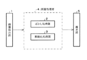
本発明に係る画像処理装置は、例えばBGRの各色の画像データに基づいて感光材料である印画紙を露光することにより、印画紙上に画像を焼き付けるものであり、図2に示すように、画像取込部1、ぼかし処理部2および鮮鋭化処理部3を有する画像処理部4、並びに露光部5を備えている。
【0068】
画像取込部1は、ネガフィルムを透過する光を測光することによってネガフィルムに記録された画像(以下、元画像とも記載する)を取り込むスキャナであり、例えば、ネガフィルムに光を照射する光源と、BGRの各色フィルタおよびCCD(Charge Coupled Device) で構成された単板式または3板式のCCDカメラとで構成されている。そして、ネガフィルムおよび各色フィルタを透過した光をBGR毎にCCDにて受光することにより、画像取込部1は、受光量に応じた電気信号をBGR毎に画像処理部4へ送る。これにより、元画像の各画素の色彩および濃度に対応する画像データがBGR毎に得られることになる。
【0069】
画像処理部4は、画像取込部1から送られてきたBGR毎の画像データに、ノイズ除去処理、鮮鋭化処理、CCDの読み取りムラや露光ヘッドの露光ムラに対する補正処理、印画紙の発色特性を考慮したガンマ補正処理等、各種の画像処理を施すものである。また、画像処理部4は、画像処理装置に組み込まれたマイクロプロセッサおよび/またはDSP(Digital Signal Processor)などによって構成されてもよいし、装置の外部に設けられたPC(Personal Computer) によって構成されてもよい。なお、画像処理部4には、画像取込部1からの画像データを一時的に格納するメモリと、露光部5での露光動作を制御する制御部(ともに図示せず)も備えられている。
【0070】
画像処理部4を構成するぼかし処理部2は、画像データを濃度データと色データとに分離し、2次元座標空間における濃度データの変化に対応して、色データのぼかし処理と濃度データのぼかし処理との割合を変化させる構成を備えているが、その詳細は後述する。
【0071】
画像処理部4を構成する鮮鋭化処理部3は、ぼかし処理部2で色ノイズおよび濃度ノイズが除去された画像データに対して、画像中の輪郭部をはっきり見せる鮮鋭化処理を、操作者の指示に応じて適宜行うものである。なお、画像取込部1が出力した画像データを鮮鋭化処理部3に入力し、鮮鋭化処理を行った後に、ぼかし処理部2でノイズ除去を行ってもよく、この場合にも、従来より高品位の画像を得ることができる。
【0072】
しかしながら、鮮鋭化処理の後でぼかし処理を行う場合、鮮鋭化の度合いに応じて最適なぼかしの度合いを変更しなければならなくなる。これに対し、ぼかし処理を先に行う場合には、鮮鋭化の度合いを考慮する必要が無いので、前者より処理が簡単になるというメリットがある。
【0073】
露光部5は、画像処理部4から送られるBGRの各画像データに基づいて印画紙への光の照射/非照射を各画素毎に制御し、画像を印画紙に焼き付けるものである。光の照射を制御する手段としては、例えば、PLZT露光ヘッド、DMD(デジタルマイクロミラーデバイス)、LCD(液晶表示装置)、LED(発光ダイオード)パネル、レーザー、FOCRT(Fiber Optic Cathode Ray Tube)、CRT(Cathode Ray Tube)等が考えられる。なお、PLZT露光ヘッド、DMD、LCD等の自発光型でない制御手段を用いる場合には、光源が別途必要であることは言うまでもない。また、必要に応じて、BGRの回転フィルタや焼付レンズなどの集光レンズも配置される。
【0074】
なお、上記PLZTは、ジルコン酸鉛(PbZrO3 )とチタン酸鉛(PbTiO3 )とを適当な比率で固溶体としたもの(PZT)に、ランタンを添加してホットプレスして得られる(Pb1-x Lax )(Zry Ti1-y )1-x/4 O3 系固溶体である。PLZTは、液晶と同様に偏光板と組み合わせ、電圧を印加することによって、光の透過光量を制御することができる。
【0075】
また、本実施の形態の画像処理装置は、解像度が2167dpiであり、ほぼフィルム粒子レベルの画像を取り込んで印画紙に焼き付ける能力を持っている。
【0076】
次に、ぼかし処理部2の構成を詳細に説明する。図1に示すように、ぼかし処理部2は、大きく分けて、Y/C分離部6(データ分離部)、ノイズ除去割合演算部7(平滑化割合算出部)およびノイズ除去部8とを備えている。
【0077】
Y/C分離部6は、画像取込部1から入力されるBGRの各画像データをYCCデータに変換、すなわち輝度データ(濃度データ)YYxyと色差データBYxy・RYxy(色データ)とに分離する働きをする。なお、輝度データYYxyと色差データBYxy・RYxyとに付された記号x,yは、画像取込部1のCCDにおける各素子の位置を、2次元座標で表したものである。
【0078】
ノイズ除去割合演算部7は、2次元座標空間における輝度データYYxyの変化を算出し、該変化に基づいて、色差データBYxy・RYxyのぼかし処理と輝度データYYxyのぼかし処理との割合を、画像の単位領域毎に算出し、ノイズ除去部8に出力する働きをする。より具体的には、ノイズ除去割合演算部7は、輝度データYYxyの変化から画像中の輪郭部と非輪郭部とを識別し、輪郭部ではぼかし処理を行わないようにする一方、非輪郭部では色差データBYxy・RYxyのぼかし処理の割合を輝度データYYxyのぼかし処理の割合より大きく設定する。
【0079】
なお、図3に示すように、一例として、ある注目画素を中心とする1辺7画素(7×7)の正方形領域を上記画像の単位領域とし、単位領域毎にぼかし処理を行うことを、画像の全領域に対して繰り返すことにする。上記単位領域は、1つ1つの画素が集合することによって、画像本来の色濃度を再現できる程度の大きさに設定されている。この理由は次のとおりである。
【0080】
ぼかし処理とは、ある注目画素の色差データBYxy・RYxyおよび輝度データYYxyのそれぞれの一部または全部を、単位領域における各データ毎の平均値で置換して平滑化する処理である。これによって、注目画素が周囲の画素から突出したノイズである場合に、ノイズデータの一部または全部が周囲の画素の平均値データに置換されるため、ノイズが低減されることになる。
【0081】
すると、ノイズは規則正しく配列されているものではないが、単位領域の大きさ(画素数)を小さくし過ぎると、その単位領域内にノイズが存在していれば、ノイズの影響が強く残った平均値データが求まってしまうし、単位領域の大きさ(画素数)を大きくし過ぎると、複数の異なるノイズの影響を受けた平均値データが求まってしまい、どちらもノイズの適切な低減にとって都合が悪いことは、明らかである。
【0082】
したがって、注目画素の周囲の画素数を少しずつ増やして領域を広げていったときに、画像の色濃度の傾向や、一連のムラ状態が現れ始める領域の大きさが、ほぼ7画素×7画素ということである。これは、CRTを近くで見るとBGRの細かい点(ドット)が独立して発光しているだけにしか見えないが、CRTから少し離れると、見える範囲が広がって色濃度が見えてくるのに似ている。CRTで絵を構成するドットがフィルム粒子に相当していると考えると、本発明を理解しやすくなる。
【0083】
なお、ノイズとは、ある画素に突発的に出現する異質の色濃度、あるいは何らかの周期性(縞模様等)を持った色濃度を指すが、本発明が低減させようとしているノイズは、フィルム粒子の発色特性が均一に分布していないことに起因するフィルム粒子ノイズである。
【0084】
フィルム粒子ノイズの一例を図8に示す。図8は、画像取込部1から取り込んだ画像データを、ぼかし処理を一切行うことなく出力した結果(図5)の一部であり、画像取込部1から取り込んだ画像データを拡大処理し、左目頭付近の領域をトリミングして出力した結果である。図8の顔の地肌部分には、フィルム粒子ノイズとして、粒子状の細かな濃淡の変化が現れていることがわかる。このようなフィルム粒子ノイズが、図5の全体画像において、ざらつき感となって発現するのである。
【0085】
さて、ノイズ除去割合演算部7は、ノイズ除去の割合を色ノイズおよび濃度ノイズについて定めるために、分散値演算部9、色ノイズ除去割合演算部10、濃度ノイズ除去割合演算部11および基準設定部12を備えている。
【0086】
分散値演算部9は、Y/C分離部6から入力される輝度データYYxyの変化を求めるために、輝度データYYxyの分散値DPを後述のように上記単位領域毎に算出する。
【0087】
色ノイズ除去割合演算部10は、分散値演算部9から入力される分散値DPを用いて、ある注目画素の色差データBYxy・RYxyのそれぞれを、単位領域における各データBYxy・RYxy毎の平均値によって、どのくらいの割合で置換するかを決める色ノイズ除去率パラメータRCを算出する。
【0088】
また、濃度ノイズ除去割合演算部11は、色ノイズ除去割合演算部10から入力される色ノイズ除去率パラメータRCを用いて、ある注目画素の輝度データYYxyを、単位領域における輝度データYYxyの平均値によって、どのくらいの割合で置換するかを決める濃度ノイズ除去率パラメータRDを算出する。
【0089】
基準設定部12は、後述の第1の基準値T1 を分散値DPについて設定し、第1の基準値T1 を色ノイズ除去割合演算部10に対して出力すると共に、後述の第2の基準値T2 を分散値DPについて設定し、第2の基準値T2 を濃度ノイズ除去割合演算部11に対して出力する。
【0090】
なお、上記第1の基準値T1 は、後で詳述するが、色ノイズおよび濃度ノイズに対して、ぼかし処理を一切行わない領域を決める基準となる。一方、第2の基準値T2 は、色ノイズ除去は行うが、濃度ノイズ除去は行わない領域を決める基準となる。また、第1の基準値T1 および第2の基準値T2 は、基準設定部12に対する外部からの入力によって適宜変更することが可能である。
【0091】
次に、ノイズ除去部8は、平均値演算部13、色ノイズ除去部14および濃度ノイズ除去部15を備えている。
【0092】
平均値演算部13は、色差データBYxy・RYxyおよび輝度データYYxyそれぞれの、上記単位領域あたりの平均値を求め、それぞれ平均色差データBYav・RYavおよび平均輝度データYYavとして出力する。
【0093】
色ノイズ除去部14は、Y/C分離部6から入力される色差データBYxy・RYxyと、平均値演算部13から入力される平均色差データBYav・RYavと、色ノイズ除去割合演算部10から入力される色ノイズ除去率パラメータRCとを用いて、色ノイズ除去率パラメータRCから定まる割合で、色差データBYxy・RYxyを平均色差データBYav・RYavに置換し、置換色差データBYxy’・RYxy’を出力する。なお、色ノイズ除去率パラメータRCの値によっては、色ノイズ除去部14は、上記置換によるぼかし処理を行わず、色差データBYxy・RYxyをそのまま出力する。
【0094】
濃度ノイズ除去部15は、Y/C分離部6から入力される輝度データYYxy、平均値演算部13から入力される平均輝度データYYavと、濃度ノイズ除去割合演算部11から入力される濃度ノイズ除去率パラメータRDとを用いて、濃度ノイズ除去率パラメータRDから定まる割合で、輝度データYYxyを平均輝度データYYavに置換し、置換輝度データYYxy’を出力する。なお、濃度ノイズ除去率パラメータRDの値によっては、濃度ノイズ除去部15は、上記置換によるぼかし処理を行わず、輝度データYYxyをそのまま出力する。
【0095】
上記の構成によるフィルム粒子ノイズの除去処理について、以下に具体的に説明する。本発明によれば、画像取込部1によってネガフィルムから読み取られたBGR毎の画像データは、Y/C分離部6によって、色差データBYxy・RYxyおよび輝度データYYxyに分離され、ノイズ除去部8において、各データBYxy・RYxy、YYxyからフィルム粒子ノイズが除去される。すなわち、BGR毎の画像データに含まれたフィルム粒子ノイズは、色ノイズと濃度ノイズとに分けて除去される。
【0096】
また、画像中の輪郭部を保存するように、輝度データYYxyの変化から輪郭部を区別し、輪郭部ではぼかし処理を行わず、輪郭部から遠ざかる程、つまり色や濃度の変化が小さい画像の平坦部に近づく程、ぼかし処理を強め、かつ、ぼかし処理を行う領域では、色ノイズ除去処理の除去強度を強くする一方、濃度ノイズ除去処理の除去強度を弱くするようなアルゴリズムで、ノイズ除去割合演算部7が、上記色ノイズ除去率パラメータRCと濃度ノイズ除去率パラメータRDとを算出するようになっている。
【0097】
上記輝度データYYxyの変化は、分散値演算部9によって、上記分散値DPとして求められる。分散値演算部9は、分散値DPを、図3に示す7画素×7画素の単位領域毎に、以下の算出式
【0098】
【数1】
によって計算する。
【0100】
なお、分散値DPを求めるための上式は、計算を高速化させることをねらった近似式であり、本来の分散の定義に従った算出式は、単位領域内の画素数をNとして、
Xav= ΣXi /N 〔式1〕
DP= Σ(Xi −Xav)2 /N 〔式2〕
となる。
【0101】
ところで、分散値DPは、単位領域内の49画素の濃度に変化が有る程、式2における2乗計算の効果により、大きな値を持つ。画像中の平坦部では色彩変化および濃度変化が小さいか殆ど無いに等しいのに対し、画像中の輪郭部ではその逆となり、特に濃度変化が大きい。したがって、輝度データYYxyの変化として算出した分散値DPが大きい単位領域は、画像中の輪郭部かそれに近い領域に属しているとみなすことができる。
【0102】
そこで、本発明の目的の1つとして、画像中の輪郭部ではぼかし処理を行わないようにするためには、分散値DPに閾値を設定し、閾値以上の分散値DPを持つ単位領域に対しては、ぼかし処理を一切行わないようにすればよい。そのような閾値を、基準設定部12で上記第1の基準値T1 として設定する。
【0103】
また、本発明の他の目的として、輪郭部から遠ざかる程、ぼかし処理を強めるためには、単位領域の中央に位置する注目画素の色差データBYxy・RYxyおよび輝度データYYxyのそれぞれを、単位領域内の49画素の平均値で置換する割合を、輪郭部から遠ざかるに従って、大きくすればよい。
【0104】
さらに、本発明のさらに他の目的として、ぼかし処理を行う領域では、色ノイズ除去処理の除去強度を強くする一方、濃度ノイズ除去処理の除去強度を弱くするためには、色差データBYxy・RYxyに関して平均値に置換する割合を、輝度データYYxyに関して平均値に置換する割合より常に大きく設定すればよい。なお、本発明では、基準設定部12で上記第1の基準値T1 より小さい値の第2の基準値T2 を設定し、分散値DPが第2の基準値T2 より小さい単位領域では、色ノイズ除去(割合大)と濃度ノイズ除去(割合小)とを行い、分散値DPが第2の基準値T2 を超える単位領域では、濃度ノイズ除去を行わず、色ノイズ除去のみを行うようにしている。
【0105】
以上のアルゴリズムをグラフ化した一例を図4に示す。図4における各設定値は、
【0106】
なお、色ノイズ除去率パラメータRCは、0のとき、色差データBYxy・RYxyを平均値に置換する割合を1、つまり色差データBYxy・RYxyを完全に各平均値に置換し、1のとき、色差データBYxy・RYxyを平均値に置換する割合を0、つまり色差データBYxy・RYxyをそのまま保存するように、線形比率によって置換率を決める変数である。
【0107】
また、濃度ノイズ除去率パラメータRDについても同様であるが、分散値DPが0から第2の基準値T2 (120)の間で、色ノイズ除去の場合と同じ線形比率で濃度ノイズ除去を行うように、濃度ノイズ除去率パラメータRDを設定した。すなわち、分散値DPが0のとき、RDを0.6に設定したが、これは実験的に定めたもので、分散値DPが0から120の間となる単位領域について、置換率が0.4(=1−0.6)を超えないように輝度データYYxyを平均値に置き換えるようにすると、印画紙に焼き付けた画像の質感として望ましい状態が得られたことに基づいている。
【0108】
上記のアルゴリズムで、各パラメータRC・RDがそれぞれ色ノイズ除去割合演算部10および濃度ノイズ除去割合演算部11にて算出されるが、色ノイズ除去部14は、Y/C分離部6から入力される色差データBYxy・RYxyと、平均値演算部13から入力される平均色差データBYav・RYavと、色ノイズ除去割合演算部10から入力される色ノイズ除去率パラメータRCとを用いて、
BYxy’=BYav×(1−RC)+BYxy×RC
RYxy’=RYav×(1−RC)+RYxy×RC
に従って、色ノイズが除去された置換色差データBYxy’・RYxy’を求める。
【0109】
また、濃度ノイズ除去部15は、Y/C分離部6から入力される輝度データYYxy、平均値演算部13から入力される平均輝度データYYavと、濃度ノイズ除去割合演算部11から入力される濃度ノイズ除去率パラメータRDとを用いて、
YYxy’=YYav×(1−RD)+YYxy×RD 〔式5〕
に従って、濃度ノイズが除去された置換輝度データYYxy’を求める。
【0110】
なお、上記平均色差データBYav・RYavおよび平均輝度データYYavは、平均値演算部13にて、以下の算出式
【0111】
【数2】
に従って計算される。
【0113】
以上の算出式1〜5を用いたぼかし処理部2の動作を具体的に説明する。ただし、説明の便宜上、本願の従来技術の説明に用いた3×3画素の輝度データを例に取る。
【0114】
例えば、Y/C分離部6が、画像取込部1から入力されたBGRの画像データから、輝度データYYxyとして、画像の平坦部における3×3画素の単位領域について、
51 49 53
52 50 49
48 51 47
を生成し、画像の輪郭部における3×3画素の単位領域について、
10 30 70
15 50 90
20 80 85
を生成し、フィルム粒子ノイズを含んだ画像の平坦部における3×3画素の単位領域について、
45 49 45
49 74 49
45 49 45
を生成したとする。
【0115】
すると、まず、平均値演算部13が、上記式1に従って、各単位領域の平均輝度データYYavを計算し、画像の平坦部A、輪郭部B、ノイズ付き平坦部Cについて、
YYav(A)=50、YYav(B)=50、YYav(C)=50
を算出する。
【0116】
次に、分散値演算部9が、上記式2に従って、平均値演算部13から入力された各平均輝度データYYavと、Y/C分離部6から入力される各輝度データYYxyとを用いて各単位領域の分散値DPを計算し、
DP(A)=3.3、DP(B)=916.7、DP(C)=75.6
を算出する。なお、前述のように、実際には、分散値演算部9は、計算の高速化の為に、前記〔数1〕式に従って、分散値DPを算出する。
【0117】
続いて、色ノイズ除去割合演算部10が、分散値演算部9から入力される分散値DPを用い、上記式3に従って各単位領域の色ノイズ除去率パラメータRCを計算し、
RC(A)=0.01、RC(B)=1、RC(C)=0.25
を算出する。
【0118】
次に、濃度ノイズ除去割合演算部11が、色ノイズ除去割合演算部10から入力される色ノイズ除去率パラメータRCを用い、上記式4に従って各単位領域の濃度ノイズ除去率パラメータRDを計算し、
RD(A)=0.61、RD(B)=1、RD(C)=0.85
を算出する。
【0119】
最後に、濃度ノイズ除去部15が、Y/C分離部6から入力される輝度データYYxy、平均値演算部13から入力される平均輝度データYYavおよび濃度ノイズ除去割合演算部11から入力される濃度ノイズ除去率パラメータRDを用い、上記式5に従って、各単位領域の注目画素について置換輝度データYYxy’を計算し、注目画素の輝度データYYxyを置換輝度データYYxy’に置換する。このような処理を全画素に施すことにより、全輝度データYYxyが置換輝度データYYxy’に置換される。
【0120】
例えば、上記の画像の平坦部における注目画素の輝度データYYxy=50について、置換輝度データYYxy’を計算すると、置換輝度データYYxy’=50となり、輝度データYYxy=50と偶々一致した結果になるため、元の輝度データと変わらない
51 49 53
52 50 49
48 51 47
を生成する。なお、平坦部では、元々ぼかし効果を得る必要性があまり無い領域である。
【0121】
また、画像の輪郭部については、濃度ノイズ除去率パラメータRDが1なので、平均輝度データYYavの置換率は0となり、元の輝度データYYxyがそのまま保存される。この結果、本発明のぼかし処理では、画像の非輪郭部でぼかしの効果が得られ、ノイズを除去することができる一方、画像の輪郭部はぼかしの効果を受けないため、画像のメリハリが失われないことになる。
【0122】
さらに、ノイズ付き平坦部における注目画素の輝度データYYxy=74について、同様に上記式5に従って置換輝度データYYxy’が計算され、置換輝度データYYxy’=70が得られる。したがって、
45 49 45
49 70 49
45 49 45
を生成する。この分散値DP(C)を計算すると55.8となるので、輝度データYYxyのばらつきが小さくなり、かつノイズのピークが小さくなるように変換され、ノイズ低減効果の得られたことがわかる。なお、実際の処理では、注目画素の輝度データYYxy=74だけではなく、その隣接画素についても、輝度データYYxyを置換輝度データYYxy’に順次置き換えるので、実際の分散値DP(C)はもっと小さな値となる。
【0123】
なお、上記の例で、第2の基準値T2 を変更し、現在の120より大きな値に設定し直せば、ノイズ除去率をさらに高めることができる。例えば、第2の基準値T2 を180に設定すると、式4は、RD=RC+0.4となるから、RD(C)=0.65になる。このRDを用いて、置換輝度データYYxy’を計算すると、
45 49 45
49 66 49
45 49 45
となり、この分散値DP(C)を計算すると39.2となるので、フィルム粒子ノイズはさらに目立たなくなることがわかる。
【0124】
以上説明した本発明の画像処理方法を、画像取込部1が読み込んだ画像データに適用した場合の結果を図5ないし図10に示す。
【0125】
図5は、前述したように、画像取込部1が読み込んだ画像データに対してノイズ除去を一切行わず、そのまま露光部5に出力した画像データの出力結果(元画像)を示している。
【0126】
図6は、画像取込部1が読み込んだ画像データに対して色ノイズ除去のみを施し、露光部5に出力した画像データの出力結果を示している。
【0127】
図7は、画像取込部1が読み込んだ画像データに対して色ノイズ除去および濃度ノイズ除去を施し、露光部5に出力した画像データの出力結果を示している。
【0128】
図5〜図7について、顔の地肌、あるいは服の素地のざらつき感を比較すると、図5の元画像のざらつき感が、図6では低減され、図7でより一層低減されて滑らかになっていることがわかる。また、目鼻立ちの輪郭や、身体の輪郭のような画像の輪郭部の鮮鋭度については、図5〜図7において目立つ差異が認められないこともわかる。
【0129】
この違いを、フィルム粒子レベルで確認しやすくするため、図5〜図7に用いた画像データに拡大処理を施し、左目頭付近の領域をトリミングした画像の出力結果を図8〜図10に示す。これらの出力結果から、画像にざらつき感をもたらすフィルム粒子ノイズは、図8〜図10にかけて徐々に改善されていることや、輪郭部の状態には、殆ど差異が認められず、図6および図7の画像において、輪郭部がほぼそのまま保存されていることを確認することができる。
【0130】
以上で説明した画像の輪郭部を保存したノイズ除去処理は、その処理を実行するプログラムで実現される。このプログラムはコンピュータで読み取り可能な記録媒体に格納されている。本発明では、この記録媒体として、図2の画像処理部4で処理が行われるために必要な図示していないメモリ(例えばROMそのもの)であってもよいし、また図示していないが外部記憶装置としてプログラム読み取り装置が設けられ、そこに記録媒体を挿入することで読み取り可能なプログラムメディアであってもよい。
【0131】
上記いずれの場合においても、格納されているプログラムはマイクロプロセッサ(図示せず)のアクセスにより実行される構成であってもよいし、格納されているプログラムを読み出し、読み出したプログラムを画像処理部4の図示されていないプログラム記憶エリアにダウンロードすることにより、そのプログラムが実行される構成であってもよい。この場合、ダウンロード用のプログラムは予め本体装置に格納されているものとする。
【0132】
ここで、上記プログラムメディアは、本体と分離可能に構成される記録媒体であり、磁気テープやカセットテープ等のテープ系、フロッピーディスクやハードディスク等の磁気ディスクやCD−ROM/MO/MD/DVD等の光ディスクのディスク系、ICカード(メモリカードを含む)/光カード等のカード系、あるいはマスクROM、EPROM、EEPROM、フラッシュROM等による半導体メモリを含めた固定的にプログラムを担持する媒体であってもよい。
【0133】
また、本発明においては、インターネットを含む通信ネットワークと接続可能なシステム構成であることから、通信ネットワークからプログラムをダウンロードするように流動的にプログラムを担持する伝送媒体を適用することもできる。なお、このように通信ネットワークからプログラムをダウンロードする場合には、そのダウンロード用プログラムは予め本体装置に格納しておくか、あるいは別な記録媒体からインストールされるものであってもよい。
【0134】
なお、記録媒体に格納されている内容としてはプログラムに限定されず、データであってもよい。
【0135】
【発明の効果】
本発明の請求項1に係る画像処理方法は、以上のように、画像データを濃度データと色データとに分離し、2次元座標空間における濃度データの変化に対応して、色データの平滑化処理と濃度データの平滑化処理との割合を変化させる処理を有している。
【0136】
それゆえ、2次元座標空間における濃度データの変化に対応して、色データの平滑化処理と濃度データの平滑化処理との割合を変化させることで、色データの平滑化処理による色ノイズ除去効果と、濃度データの平滑化処理による濃度ノイズ除去効果とのバランスを最適化することができるので、画像中の輪郭部の保存と画像のざらつき低減との双方に好ましい結果を得ることができるという効果を奏する。
【0137】
本発明の請求項2に係る画像処理方法は、以上のように、請求項1に記載の処理に加えて、上記濃度データの変化の程度に関して第1の基準値を設定し、濃度データの変化が上記第1の基準値より小さい画像領域では、色データの平滑化処理を行った後で、必要に応じて濃度データの平滑化処理を行うようにしている。
【0138】
それゆえ、画像の平坦部に近い領域では、輪郭情報をぼかす効果が、濃度ノイズ除去に比べて小さい色データの平滑化処理を優先し、濃度データの平滑化処理は、行った方が好ましい結果になる場合に行うようにすることによって、画像中の輪郭部の保存と画像のざらつき低減との双方に、一層好ましい結果を得ることができるという効果を、請求項1に記載の方法による効果に加えて奏する。
【0139】
本発明の請求項3に係る画像処理方法は、以上のように、請求項1または2に記載の処理に加えて、上記濃度データの変化の程度に関して第1の基準値を設定し、濃度データの変化が上記第1の基準値より小さい画像領域では、色データの平滑化処理の割合を濃度データの平滑化処理の割合より大きくする処理を有している。
【0140】
それゆえ、平坦部に近い領域では、輪郭情報をぼかす効果が、濃度ノイズ除去に比べて小さい色データの平滑化処理の割合を相対的に大きくすることによって、請求項2の方法と同様に、画像中の輪郭部の保存と画像のざらつき低減との双方に、一層好ましい結果を得ることができるという効果を奏する。
【0141】
本発明の請求項4に係る画像処理方法は、以上のように、請求項2または3に記載の処理に加えて、上記濃度データの変化の程度に関して、上記第1の基準値より小さい値を持つ第2の基準値を設定し、濃度データの変化が上記第2の基準値より大きい画像領域では、濃度データの平滑化処理を行わないようにしている。
【0142】
それゆえ、画像の輪郭部をぼかす効果が大きい濃度ノイズ除去について、濃度データの変化が第2の基準値より大きい領域では行わないようにするので、画像の輪郭部を保存する効果を一層高めることができる一方、色ノイズ除去については、請求項2または3に記載のとおり、少なくとも、濃度データの変化が第1の基準値より小さい領域で行うので、画像のざらつき低減の効果は、変わりなく得ることができるという効果を、請求項2または3に記載の方法による効果に加えて奏する。
【0143】
本発明の請求項5に係る画像処理方法は、以上のように、請求項2ないし4のいずれか1項に記載の処理に加えて、濃度データの変化が上記第1の基準値より大きい画像領域では、濃度データの平滑化処理および色データの平滑化処理の双方を行わないようにしている。
【0144】
それゆえ、画像の輪郭部に近い領域では、濃度ノイズ除去も色ノイズ除去も行わないようにするので、画像の輪郭部を最も適切に保存することができる画像処理方法を提供できるという効果を、請求項2ないし4のいずれか1項に記載の方法による効果に加えて奏する。
【0145】
本発明の請求項6に係る画像処理方法は、以上のように、請求項1ないし5のいずれか1項に記載の処理に加えて、色データの平滑化処理と濃度データの平滑化処理との割合を、濃度データの分散値に基づいて変化させる処理を有している。
【0146】
それゆえ、濃度データの変化が的確に反映され、かつ計算のしやすいパラメータである濃度データの分散値に基づくことによって、色ノイズ除去効果と濃度ノイズ除去効果とのバランスを最適化することが容易になり、かつ、複雑な計算処理を行う必要が無いため、計算速度が遅くならずに済み、またハード化への適用も比較的容易な画像処理方法を提供することができるという効果を、請求項1ないし5のいずれか1項に記載の方法による効果に加えて奏する。
【0147】
本発明の請求項7に係る画像処理装置は、以上のように、
(1) 画像データを濃度データと色データとに分離するデータ分離部と、
(2) 色データの平滑化処理を行う色ノイズ除去部と、
(3) 濃度データの平滑化処理を行う濃度ノイズ除去部と、
(4) 2次元座標空間における濃度データの変化を算出し、該変化に基づいて、色データの平滑化処理と濃度データの平滑化処理との割合を、画像の単位領域毎に算出し、色ノイズ除去部および濃度ノイズ除去部に出力する平滑化割合算出部とを備えている構成である。
【0148】
それゆえ、各部の動作によって、画像中の輪郭部が保存され、画像のざらつきが低減された、メリハリの有る高品位画像を得ることができるという効果を奏する。
【0149】
本発明の請求項8に係る画像処理装置は、以上のように、請求項7に記載の構成に加えて、上記平滑化割合算出部が、濃度データの変化の程度に関して設定された第1の基準値と、濃度データの変化とを比較し、濃度データの変化が上記第1の基準値より小さい画像領域では、色データの平滑化処理の割合を濃度データの平滑化処理の割合より大きくする算出式に基づいて、該割合を算出する構成である。
【0150】
それゆえ、請求項3の発明と同様に、画像中の輪郭部の保存と画像のざらつき低減との双方に一層好ましい結果を得ることができるという効果を、請求項7に記載の構成による効果に加えて奏する。
【0151】
本発明の請求項9に係る画像処理装置は、以上のように、請求項8に記載の構成に加えて、上記平滑化割合算出部が、上記濃度データの変化の程度に関して、上記第1の基準値より小さい値を持つように設定された第2の基準値と、濃度データの変化とを比較し、濃度データの変化が上記第2の基準値より大きい画像領域では、濃度データの平滑化処理を行わないようにする算出式に基づいて、該割合を算出する構成である。
【0152】
それゆえ、請求項4の発明と同様に、画像の輪郭部を保存する効果を一層高めることができると共に、画像のざらつき低減の効果についても、変わりなく得ることができるという効果を、請求項8に記載の構成による効果に加えて奏する。
【0153】
本発明の請求項10に係る画像処理装置は、以上のように、請求項8または9に記載の構成に加えて、上記平滑化割合算出部が、濃度データの変化が上記第1の基準値より大きい画像領域では、濃度データの平滑化処理および色データの平滑化処理の双方を行わないようにする算出式に基づいて、該割合を算出する構成である。
【0154】
それゆえ、請求項5の発明と同様に、画像の輪郭部を最も適切に保存することができる画像処理装置を提供できるという効果を、請求項8または9に記載の構成による効果に加えて奏する。
【0155】
本発明の請求項11に係る画像処理装置は、以上のように、請求項8ないし10のいずれか1項に記載の構成に加えて、上記平滑化割合算出部が、上記基準値を、外部からの入力によって可変的に設定する基準設定部を備えていることを特徴としている。
【0156】
それゆえ、第1の基準値も、第2の基準値も、固定的なものではなく、基準設定部を介して可変させることができるので、得られた画像の画質を確認しながら、画像の輪郭部の保存効果と、画像のざらつき低減効果とを最適なバランスにする基準値を選択することが可能になるという効果を、請求項8ないし10のいずれか1項に記載の構成による効果に加えて奏する。
【0157】
本発明の請求項12に係る記録媒体は、以上のように、請求項1ないし6のいずれか1項に記載の画像処理方法を実行するプログラムを記録したことを特徴としている。
【0158】
それゆえ、該プログラムを画像処理装置にセットアップすることによって、請求項1ないし6のいずれか1項に記載の画像処理方法をユーザーが実行することができるという効果を奏する。
【図面の簡単な説明】
【図1】本発明に係る画像処理装置のぼかし処理部の構成を示すブロック図である。
【図2】上記画像処理装置の要部構成を模式的に示すブロック図である。
【図3】色データの平滑化処理と濃度データの平滑化処理とを施す、繰り返し単位としての画像の単位領域を示す説明図である。
【図4】色データの平滑化処理および濃度データの平滑化処理のアルゴリズムの一例をグラフ化して示す説明図である。
【図5】色ノイズ除去および濃度ノイズ除去をいずれも施していない画像データの出力結果を示す図面代用写真である。
【図6】図5に用いた画像データに色ノイズ除去を施した画像データの出力結果を示す図面代用写真である。
【図7】図5に用いた画像データに色ノイズ除去および濃度ノイズ除去を施した画像データの出力結果を示す図面代用写真である。
【図8】図5に用いた画像データに拡大処理を施し、左目頭付近の領域をトリミングした出力結果を示す図面代用写真である。
【図9】図6に用いた画像データに拡大処理を施し、左目頭付近の領域をトリミングした出力結果を示す図面代用写真である。
【図10】図7に用いた画像データに拡大処理を施し、左目頭付近の領域をトリミングした出力結果を示す図面代用写真である。
【図11】(a)は、鮮鋭化処理を施す前の画像中の輪郭部における濃度変化の様子を示す説明図であり、(b)は、鮮鋭化処理を施した後の画像中の輪郭部における濃度変化の様子を示す説明図である。
【符号の説明】
6 Y/C分離部(データ分離部)
7 ノイズ除去割合演算部(平滑化割合算出部)
12 基準設定部
14 色ノイズ除去部
15 濃度ノイズ除去部
BYxy 色差データ(色データ)
RYxy 色差データ(色データ)
YYxy 輝度データ(濃度データ)
DP 分散値
RC 色ノイズ除去率パラメータ(色データの平滑化処理の割合)
RD 濃度ノイズ除去率パラメータ(濃度データの平滑化処理の割合)
T1 第1の基準値
T2 第2の基準値[0001]
BACKGROUND OF THE INVENTION
According to the present invention, when image formation is performed on a photosensitive material using digital image data, image quality can be improved by reducing particulate noise that causes a rough feeling of the image without blurring the contour portion in the image. The present invention relates to an image processing method that can be improved, an image processing apparatus that performs the image processing method, and a recording medium that records a program that executes the image processing method.
[0002]
[Prior art]
Conventionally, analog exposure has been carried out for many years as a photographic printing, in which a photographic film on which an original image is recorded is irradiated with light, and the light transmitted through the photographic film is irradiated onto a photographic paper. In recent years, in addition to analog exposure, based on digital image data obtained by reading an image on a photographic film with a scanner or digital image data obtained by photographing with a digital camera, red, green, blue, etc. The digital exposure for printing is performed by irradiating the monochrome light on the photographic paper for each pixel.
[0003]
By the way, in a photographic printing apparatus that performs digital exposure, the pixel density of an image printed on photographic paper is determined by the resolution of the scanner and the resolution of the exposure head. In general, the particle density constituting an image of a positive film is about 2500 dpi, and currently, a digital exposure photographic printing apparatus having a resolution comparable to the particle density has appeared on the market. Therefore, such a digital exposure photographic printing apparatus can capture an image of almost film grain level and print it on a photographic paper, so that a print image comparable to that of analog exposure can be obtained. It has become.
[0004]
Incidentally, the particle density of 2500 dpi corresponds to the number of pixels of 3445 × 2362 in the 135F size (3.6 cm × 2.4 cm) photographic film.
[0005]
In addition, since a photographic printing apparatus that performs digital exposure can process image data, it has a feature that various special effects that cannot be performed by an analog exposure photographic printing apparatus can be given to an image. One of them is a process called “sharpening” that gives sharpness to an outline (for example, the outline of a person in the background or the eye-nose standing of a person's face) in an image. Hereinafter, the sharpening process will be described.
[0006]
The sharpening process is a process for clearly showing the boundary between an object in an image and another object, that is, a contour. Specifically, for a target pixel constituting the contour, a density difference from a pixel adjacent to the target pixel. Data called a spatial filter that converts image data so as to increase the size of the image data is used. The simplest example is described below.
[0007]
For example, the 3 × 3 filter as the spatial filter is composed of matrix elements of coefficients that are multiplied by the density data of each pixel in a 3 × 3 pixel column.
[0008]
If there is 100 × 100 pixel image data, the above 3 × 3 filter is applied 10,000 times to a total of 10000 pixels while sequentially considering each pixel as a pixel of interest. A converted image can be obtained.
[0009]
A specific example showing the effect of using the 3 × 3 filter will be further described. For example, an image of an object such as an automobile or an airplane with a background of a road or sky is taken as an example. Backgrounds such as roads and sky include many areas that can be called flat portions of an image with almost no change in image color and shade. The 3 × 3 pixel column in the flat part of the image is, for example,
51 49 53
52 50 49
48 51 47
It is like this.
[0010]
When the 3 × 3 filter is applied to the 3 × 3 pixel image data, the numerical value of each image data is multiplied by the corresponding matrix element.
[0011]
On the other hand, in the contour portion of the object, the 3 × 3 pixel column is, for example,
10 30 70
15 50 90
20 80 85
It has become. That is, in this contour portion, the upper left side tends to be thin and the lower right side tends to be dark. If the 3 × 3 filter is applied to this,
[0012]
Further, when attention is paid to the image data “90” adjacent to the right side of the image data “50” of the target pixel, the 3 × 3 pixel column is, for example,
30 70 85
50 90 95
80 85 90
It has become. If the 3 × 3 filter is applied to this,
[0013]
FIG. 11A and FIG. 11B schematically show changes in the image data in the contour portion. That is, sharpening is a process of increasing the contrast of the contour portion by including a spike-like emphasis portion as shown in FIG. 11B in the contrast of the contour portion shown in FIG. I understand.
[0014]
As described above, when the image data is processed using the spatial filter, the flat portion of the image does not change much, whereas the contour portion changes greatly. Therefore, the image can be sharpened only by repeating this operation. .
[0015]
[Problems to be solved by the invention]
However, the conventional sharpening method has a problem of increasing the roughness of the image printed on the photographic paper.
[0016]
Since the above-described high-resolution digital exposure photographic printing apparatus can capture an image almost at the film grain level, the image baked at the same magnification as the photographic film is a collection of pixels of the film grain level. . In addition, since the color development characteristics of film particles are not completely uniform, the color and density that form the image include roughness due to fine color changes and roughness due to fine density changes, in other words, noise at the film particle level (hereinafter referred to as film particles). (Referred to as noise).
[0017]
In addition, when an image taken from a photographic film is printed on photographic paper, the film particle noise becomes more noticeable as the image is enlarged and printed.
[0018]
In other words, the conventional sharpening method not only emphasizes the contour of the image but also enhances the graininess of the photographic film, thereby increasing the roughness of the image printed on the photographic paper. For this reason, the image often becomes very unsightly. In particular, when roughness appears on the human skin, the image quality appears to be greatly reduced.
[0019]
Hereinafter, a specific example in which film particle noise is emphasized by the sharpening process will be described. Film grain noise is, for example,
45 45 45
45 90 45
45 45 45
The numerical value “90” in the center of the image data in the state as shown in FIG.
[0020]
If the 3 × 3 filter is applied to this,
[0021]
Therefore, even if the sharpening process is performed, a process that does not emphasize the rough feeling caused by the film particles is required. As a simple technique, a blurring process, that is, a process of replacing a certain target pixel with an average value obtained from surrounding pixels on the entire image can be considered. However, in such a blurring process, the outline is blurred, so that the sharpened meaning is lost.
[0022]
Alternatively, a method of performing blurring processing on the captured image data first and then performing sharpening processing is conceivable, but in this case, fine structures (details) in the image are lost.
[0023]
The present invention has been made in view of the above-described problems, and its purpose is to form film particles without blurring the contours in the image when forming an image on a photosensitive material using digital image data. An object of the present invention is to provide an image processing method capable of reducing the rough feeling caused by the image processing apparatus, an image processing apparatus for executing the image processing method, and a recording medium on which a program for executing the image processing method is recorded.
[0024]
[Means for Solving the Problems]
In order to solve the above-described problem, an image processing method according to claim 1 of the present invention separates image data into density data and color data, and changes color data in response to changes in density data in a two-dimensional coordinate space. It is characterized in that the ratio between the data smoothing process and the density data smoothing process is changed.
[0025]
In the above configuration, the film particle noise includes fine color changes, that is, color noise, and fine density changes, that is, density noise. By increasing density noise removal as a ratio at a place where density noise is conspicuous, it is possible to optimize noise removal by separately processing color noise removal and density noise removal at different ratios.
[0026]
Further, while the color change and the density change are small or almost equal in the flat part in the image, the opposite is true in the contour part in the image, and the density change is particularly large. Therefore, when the image data is divided into density data and color data, the image outline information is included more in the density data. This is also the reason why it is preferable to process color noise removal and density noise removal separately at different rates.
[0027]
Furthermore, the human eye is more likely to perceive density changes more sensitively than color changes. This is another reason why it is preferable to separately process color noise removal and density noise removal at different rates.
[0028]
Further, in order to save the contour portion in the image so as not to blur, it is only necessary to remove density noise removal and color noise removal in the image contour portion. More preferably, the image contour information is the density data. Therefore, the closer to the contour portion from the flat portion of the image, the closer the density noise removal rate is to 0, and it is better to stop the density noise removal earlier than the color noise removal. . Color noise removal has a smaller effect on blurring contour information than density noise removal, so that the effect of reducing the roughness of the image can be enhanced by performing the processing close to the contour portion of the image.
[0029]
That is, as described above, the color data is smoothed by changing the ratio between the color data smoothing process and the density data smoothing process in response to the density data change in the two-dimensional coordinate space. Since the balance between the color noise removal effect by the processing and the density noise removal effect by the density data smoothing process can be optimized, there is a favorable result for both the preservation of the contour portion in the image and the reduction of the roughness of the image. Will be obtained.
[0030]
In order to solve the above-described problem, an image processing method according to
[0031]
According to the above configuration, the region where the change in density data is larger than the first reference value is a region closer to the contour portion than the flat portion of the image, and conversely, the change in density data is smaller than the first reference value. Since the region is a region closer to the flat portion than the contour portion of the image, the region close to the contour portion can be distinguished by the first reference value.
[0032]
Therefore, in the region close to the flat portion, the effect of blurring the contour information preferentially performs the smoothing process of the color data that is smaller than the smoothing process of the density data. Thus, if the color noise removal is performed first, the density noise removal rate can be reduced as compared with the case where the density noise removal is performed alone. That is, the density data smoothing process can be performed when it is preferable to perform the density data. As a result, a more favorable result can be obtained for both the preservation of the contour portion in the image and the reduction of the roughness of the image.
[0033]
In order to solve the above-described problem, an image processing method according to a third aspect of the present invention sets a first reference value regarding the degree of change in the density data in addition to the processing according to the first or second aspect. In the image area where the change in density data is smaller than the first reference value, the ratio of the color data smoothing process is made larger than the ratio of the density data smoothing process.
[0034]
According to the above configuration, for the same reason as in the method of
[0035]
In order to solve the above-described problem, an image processing method according to a fourth aspect of the present invention includes the first reference value regarding the degree of change in the density data, in addition to the processing according to the second or third aspect. A second reference value having a smaller value is set, and density data is not smoothed in an image area where the change in density data is larger than the second reference value.
[0036]
According to the above configuration, since the region where the change in density data is smaller than the second reference value is a region closer to the flat portion of the image, by providing the first and second reference values, It can be classified into three stages: a region near the flat part, a region between the flat part and the contour part, and a region near the contour part.
[0037]
Then, density noise removal, which has a great effect of blurring the contour portion of the image, is not performed in a region where the density data change is larger than the second reference value, thereby further enhancing the effect of preserving the contour portion of the image. it can.
[0038]
On the other hand, since the color noise removal is performed at least in a region where the density data is smaller than the first reference value, the effect of reducing the roughness of the image can be obtained without change. It is.
[0039]
In order to solve the above problem, an image processing method according to a fifth aspect of the present invention is characterized in that, in addition to the processing according to any one of the second to fourth aspects, a change in density data is the first reference. In an image region larger than the value, both density data smoothing processing and color data smoothing processing are not performed.
[0040]
According to the above configuration, density noise removal and color noise removal are not performed in an image region where the change in density data is larger than the first reference value, that is, in a region near the contour of the image. According to the image processing method of the item, the contour portion of the image can be stored most appropriately.
[0041]
In order to solve the above problems, an image processing method according to a sixth aspect of the present invention includes a color data smoothing process and a density data smoothing process in addition to the process according to any one of the first to fifth aspects. It is characterized in that the ratio to the smoothing process is changed based on the dispersion value of the density data.
[0042]
According to the above configuration, the variance value of the density data is a parameter that accurately reflects changes in the density data and is easy to calculate. That is, in a region where there is no change in density data, the variance value becomes 0, and the variance value also changes from 0 to a larger value as the change in density data increases from 0.
[0043]
Therefore, by obtaining the dispersion value of the density data, it is possible to easily identify whether the value is a flat portion of the image, whether it is close to the contour portion, an intermediate region between the flat portion and the contour portion, or the like.
[0044]
Therefore, based on the dispersion value of the density data, it is easy to optimize the balance between the color noise removal effect and the density noise removal effect. In particular, since the variance value is obtained as an average of the values obtained by squaring the difference between the density data and the average value of the density data, the noise removal based on the variance value makes the image more natural by the effect of the square calculation. I think that. Further, since it is not necessary to perform complicated calculation processing, it is possible to provide an image processing method that does not slow down the calculation speed and is relatively easy to apply to hardware.
[0045]
In order to solve the above problems, an image processing apparatus according to
(1) a data separation unit that separates image data into density data and color data;
(2) a color noise removal unit that performs color data smoothing processing;
(3) a density noise removing unit that performs density data smoothing processing;
(4) The density data change in the two-dimensional coordinate space is calculated, and based on the change, the ratio between the color data smoothing process and the density data smoothing process is calculated for each unit area of the image. A smoothing ratio calculating unit that outputs to the noise removing unit and the density noise removing unit;
It is characterized by having.
[0046]
According to the above configuration, the smoothing ratio calculation unit performs the smoothing process of the color data and the smoothing process of the density data so that the effect of reducing the roughness of the image can be obtained without blurring the contour part in the image. And calculate the ratio with. The smoothing ratio calculation unit performs the calculation for each unit region of the image.
[0047]
The color noise removal unit receives the color data from the data separation unit, and receives the color noise removal rate from the smoothing rate calculation unit, thereby performing color data smoothing processing for each unit region of the image.
[0048]
The density noise removing unit also receives density data from the data separation unit and receives the density noise removal rate from the smoothing rate calculating unit, thereby performing density data smoothing processing for each unit area of the image.
[0049]
As a result, it is possible to obtain a sharp and high-quality image in which the contour portion in the image is preserved and the roughness of the image is reduced.
[0050]
According to an eighth aspect of the present invention, in order to solve the above-described problem, in addition to the configuration of the seventh aspect, the smoothing ratio calculating unit is set with respect to the degree of change in density data. The first reference value is compared with the change in the density data, and in the image area where the change in the density data is smaller than the first reference value, the ratio of the smoothing process of the color data is set as the density data smoothing process. The ratio is calculated based on a calculation formula that is larger than the ratio.
[0051]
According to said structure, a more preferable result can be obtained for both the preservation | save of the outline part in an image, and the reduction of the roughness of an image for the same reason as invention of
[0052]
In order to solve the above problem, an image processing apparatus according to a ninth aspect of the present invention, in addition to the configuration according to the eighth aspect, provides that the smoothing ratio calculation unit relates to the degree of change in the density data. The second reference value set so as to have a value smaller than the first reference value is compared with the change in the density data, and in the image area where the change in the density data is larger than the second reference value, the density The ratio is calculated based on a calculation formula that does not perform the data smoothing process.
[0053]
According to the above configuration, for the same reason as that of the invention of claim 4, the effect of preserving the contour portion of the image can be further enhanced, and the effect of reducing the roughness of the image can be obtained without change.
[0054]
According to a tenth aspect of the present invention, in order to solve the above-described problem, in addition to the configuration according to the eighth or ninth aspect, the smoothing ratio calculating unit is configured so that the change in density data is the first. In an image region larger than the reference value of 1, the ratio is calculated based on a calculation formula that does not perform both density data smoothing processing and color data smoothing processing.
[0055]
According to said structure, the image processing apparatus of this claim can preserve | save the outline part of an image most appropriately for the same reason as invention of
[0056]
In order to solve the above-described problem, an image processing apparatus according to an eleventh aspect of the present invention, in addition to the configuration according to any one of the eighth to tenth aspects, includes the smoothing ratio calculating unit including the reference It is characterized by having a reference setting unit that variably sets a value by an external input.
[0057]
According to the above configuration, the first reference value and the second reference value are not fixed and can be varied via the reference setting unit, so that the image quality of the obtained image is confirmed. However, it is possible to select a reference value that provides an optimal balance between the effect of preserving the contour of the image and the effect of reducing the roughness of the image.
[0058]
A recording medium according to a twelfth aspect of the present invention is characterized in that a program for executing the image processing method according to any one of the first to sixth aspects is recorded in order to solve the above problems.
[0059]
According to said structure, a user can perform the image processing method of any one of Claim 1 thru | or 6 by installing this program in an image processing apparatus.
[0060]
DETAILED DESCRIPTION OF THE INVENTION
[Embodiment 1]
An embodiment of the present invention will be described with reference to FIGS. 1 to 10 as follows.
[0061]
In general, since the human eye is more sensitive to density changes than color changes, strong blur processing (smoothing processing) is performed to remove color noise, while weak blur processing (smoothing processing) is performed to density noise. If this is performed, the noise removal effect is high, and the contour does not appear to be very blurred. This human visual characteristic is the first point of focus for producing the present invention.
[0062]
Next, since a change in density appears more conspicuously than a change in color in the contour portion, it can be seen that more contour information is included in the density data than in the color data. Therefore, weakening the density data blurring process compared to the color data blurring process is also effective for storing contour information.
[0063]
Nonetheless, if the blur process with strong color data and the weak blur process with density data are uniformly applied to the entire image, the contour information is completely ignored, so the sharpness of the image is too high. It doesn't become a thing. Therefore, an area that can be regarded as an outline part in the image is extracted, and the blurring process in the outline part is weakened or not performed at all, and in the non-contour part, a strong blurring process of color data and a weak blurring process of density data It was found that the contour information can be stored more effectively while maintaining the noise removal effect. The correlation between the preservation property of the contour information and the blurring processing method is the second point of focus that produces the present invention.
[0064]
From such a viewpoint, as an image processing method of the present invention, in order to reduce film particle noise included in image data read from a developed photographic film using a scanner, the image data is referred to as density data. It has been separated into color data, and has come up with a method for changing the ratio of color data blur processing and density data blur processing in response to changes in density data in a two-dimensional coordinate space.
[0065]
Furthermore, as an image processing method of the present invention, a contour portion in an image is extracted based on a change in density data in a two-dimensional coordinate space, noise removal is performed as little as possible in the contour portion, and density noise in a non-contour portion. As a result, the inventors have come up with a method for preferentially removing color noise or increasing the color noise removal rate over density noise.
[0066]
As a specific description, the configuration of an image processing apparatus that implements the image processing method of the present invention will be described.
[0067]
The image processing apparatus according to the present invention prints an image on a photographic paper by exposing the photographic paper, which is a photosensitive material, based on image data of each color of BGR, for example. As shown in FIG. An image processing unit 4 having an embedding unit 1, a
[0068]
The image capturing unit 1 is a scanner that captures an image (hereinafter also referred to as an original image) recorded on a negative film by measuring light transmitted through the negative film. For example, a light source that irradiates light on the negative film And a single-plate or three-plate CCD camera composed of BGR color filters and a CCD (Charge Coupled Device). Then, the light that has passed through the negative film and each color filter is received by the CCD for each BGR, so that the image capturing unit 1 sends an electrical signal corresponding to the amount of received light to the image processing unit 4 for each BGR. As a result, image data corresponding to the color and density of each pixel of the original image is obtained for each BGR.
[0069]
The image processing unit 4 applies noise removal processing, sharpening processing, correction processing for CCD reading unevenness and exposure head exposure unevenness to the image data for each BGR sent from the image capturing unit 1, and coloring characteristics of photographic paper. Various image processing such as gamma correction processing considering the above is performed. The image processing unit 4 may be configured by a microprocessor and / or DSP (Digital Signal Processor) incorporated in the image processing apparatus, or by a PC (Personal Computer) provided outside the apparatus. May be. The image processing unit 4 is also provided with a memory that temporarily stores image data from the image capturing unit 1 and a control unit (both not shown) that controls the exposure operation in the
[0070]
The
[0071]
The sharpening
[0072]
However, when the blurring process is performed after the sharpening process, the optimum blurring degree must be changed according to the sharpening degree. On the other hand, when the blurring process is performed first, there is no need to consider the degree of sharpening, so there is an advantage that the process is simpler than the former.
[0073]
The
[0074]
The PLZT is composed of lead zirconate (PbZrO Three ) And lead titanate (PbTiO) Three ) To a solid solution (PZT) in an appropriate ratio and obtained by hot pressing with lanthanum added (Pb 1-x La x ) (Zr y Ti 1-y ) 1-x / 4 O Three It is a system solid solution. PLZT can control the amount of transmitted light by applying a voltage in combination with a polarizing plate like liquid crystal.
[0075]
The image processing apparatus according to the present embodiment has a resolution of 2167 dpi, and has the ability to capture an image at a film grain level and print it on photographic paper.
[0076]
Next, the configuration of the
[0077]
The Y /
[0078]
The noise removal
[0079]
As shown in FIG. 3, as an example, a square area of 7 pixels per side (7 × 7) centering on a certain target pixel is used as a unit area of the image, and blurring processing is performed for each unit area. Let's repeat for the whole area of the image. The unit area is set to such a size that the original color density of the image can be reproduced by collecting pixels one by one. The reason for this is as follows.
[0080]
The blurring process is the color difference data BY of a certain target pixel. xy ・ RY xy And luminance data YY xy Is a process of substituting and smoothing a part or all of each with an average value for each data in the unit area. As a result, when the target pixel is noise protruding from the surrounding pixels, part or all of the noise data is replaced with the average value data of the surrounding pixels, so that the noise is reduced.
[0081]
Then, the noise is not regularly arranged, but if the size (number of pixels) of the unit area is too small, if noise exists in the unit area, the average of the influence of the noise remains strong If the value data is obtained, or if the size of the unit area (number of pixels) is too large, average value data affected by a plurality of different noises is obtained, both of which are convenient for appropriate noise reduction. The bad thing is clear.
[0082]
Therefore, when the area is expanded by gradually increasing the number of pixels around the target pixel, the tendency of the color density of the image and the size of the area where a series of uneven states start appearing are approximately 7 pixels × 7 pixels. That's what it means. This is because when you look closely at the CRT, you can see only the small dots (dots) of the BGR that emit light independently, but when you leave the CRT a little, the visible range will expand and the color density will be visible. It is similar. If it is considered that dots constituting a picture on a CRT correspond to film particles, the present invention can be easily understood.
[0083]
The noise refers to a different color density suddenly appearing in a certain pixel or a color density having some periodicity (such as a striped pattern). The noise to be reduced by the present invention is a film particle. This is film particle noise resulting from the uneven distribution of the color development characteristics.
[0084]
An example of film grain noise is shown in FIG. FIG. 8 is a part of the result (FIG. 5) obtained by outputting the image data acquired from the image capturing unit 1 without performing any blurring process. The image data captured from the image capturing unit 1 is enlarged. This is the result of trimming and outputting the area near the left eye. It can be seen that fine grainy changes in grain appear as film grain noise on the background of the face in FIG. Such film particle noise appears as a rough feeling in the entire image of FIG.
[0085]
Now, in order to determine the noise removal ratio for color noise and density noise, the noise removal
[0086]
The variance value calculation unit 9 receives luminance data YY input from the Y /
[0087]
The color noise removal
[0088]
Further, the density noise removal
[0089]
The
[0090]
The first reference value T 1 As will be described in detail later, this is a reference for determining a region where no blurring processing is performed for color noise and density noise. On the other hand, the second reference value T 2 Is a reference for determining a region where color noise removal is performed but density noise removal is not performed. The first reference value T 1 And the second reference value T 2 Can be appropriately changed by external input to the
[0091]
Next, the noise removing unit 8 includes an average
[0092]
The average
[0093]
The color
[0094]
The density
[0095]
The film particle noise removal processing with the above configuration will be specifically described below. According to the present invention, the image data for each BGR read from the negative film by the image capturing unit 1 is converted into the color difference data BY by the Y /
[0096]
In addition, luminance data YY is stored so as to preserve the contour portion in the image. xy The contour part is distinguished from the change of the image, and the blurring process is not performed on the contour part. In the area to be performed, the noise removal
[0097]
Luminance data YY xy Is obtained by the variance value calculation unit 9 as the variance value DP. The variance value calculation unit 9 calculates the variance value DP for each unit region of 7 pixels × 7 pixels shown in FIG.
[0098]
[Expression 1]
Calculate by
[0100]
Note that the above equation for obtaining the dispersion value DP is an approximation equation aiming at speeding up the calculation, and the calculation equation according to the original definition of dispersion is N as the number of pixels in the unit region.
X av = Σ Xi / N [Formula 1]
DP = Σ (Xi -X av ) 2 / N [Formula 2]
It becomes.
[0101]
By the way, the variance value DP has a larger value due to the effect of the square calculation in
[0102]
Therefore, as one of the objects of the present invention, in order not to perform the blurring process in the contour portion in the image, a threshold value is set for the variance value DP, and a unit region having a variance value DP equal to or greater than the threshold value is set. Therefore, it is only necessary not to perform any blurring process. Such a threshold value is set by the
[0103]
As another object of the present invention, the color difference data BY of the pixel of interest located in the center of the unit area is used to increase the blurring process as the distance from the contour portion increases. xy ・ RY xy And luminance data YY xy The ratio of replacing each of these with the average value of 49 pixels in the unit region may be increased as the distance from the contour portion increases.
[0104]
Furthermore, as another object of the present invention, in the region where the blurring process is performed, in order to increase the removal strength of the color noise removal processing while reducing the removal strength of the density noise removal processing, the color difference data BY is used. xy ・ RY xy For the luminance data YY xy It may be set to be always larger than the rate of replacement with the average value. In the present invention, the
[0105]
An example in which the above algorithm is graphed is shown in FIG. Each setting value in FIG.
[0106]
When the color noise removal rate parameter RC is 0, the color difference data BY xy ・ RY xy 1 to replace the average value with 1, that is, color difference data BY xy ・ RY xy Is completely replaced with each average value, and when 1, the color difference data BY xy ・
[0107]
The same applies to the density noise removal rate parameter RD, but the dispersion value DP is from 0 to the second reference value T. 2 Between (120), the density noise removal rate parameter RD is set so that density noise removal is performed at the same linear ratio as in the case of color noise removal. That is, when the dispersion value DP is 0, RD is set to 0.6, but this is experimentally determined. For the unit region where the dispersion value DP is between 0 and 120, the replacement rate is 0. Luminance data YY so as not to exceed 4 (= 1-0.6) xy Is replaced with the average value based on the fact that a desirable state is obtained as the texture of the image printed on the photographic paper.
[0108]
In the above algorithm, the parameters RC and RD are calculated by the color noise removal
BY xy '= BY av × (1-RC) + BY xy × RC
RY xy '= RY av × (1-RC) + RY xy × RC
According to the above, the replacement color difference data BY from which the color noise has been removed xy '・ RY xy Ask for '.
[0109]
Further, the density
YY xy '= YY av × (1-RD) + YY xy × RD [Formula 5]
The replacement luminance data YY from which density noise has been removed according to xy Ask for '.
[0110]
The average color difference data BY av ・ RY av And average luminance data YY av Is calculated by the
[0111]
[Expression 2]
Calculated according to
[0113]
The operation of the blurring
[0114]
For example, the Y /
51 49 53
52 50 49
48 51 47
For a unit area of 3 × 3 pixels in the contour of the image,
10 30 70
15 50 90
20 80 85
And a unit area of 3 × 3 pixels in the flat part of the image including film grain noise,
45 49 45
49 74 49
45 49 45
Is generated.
[0115]
Then, the average
YY av (A) = 50, YY av (B) = 50, YY av (C) = 50
Is calculated.
[0116]
Next, the variance value calculation unit 9 calculates each average luminance data YY input from the average
DP (A) = 3.3, DP (B) = 916.7, DP (C) = 75.6
Is calculated. As described above, in practice, the variance value calculation unit 9 calculates the variance value DP in accordance with the formula [1] in order to speed up the calculation.
[0117]
Subsequently, the color noise removal
RC (A) = 0.01, RC (B) = 1, RC (C) = 0.25
Is calculated.
[0118]
Next, the density noise removal
RD (A) = 0.61, RD (B) = 1, RD (C) = 0.85
Is calculated.
[0119]
Finally, the density
[0120]
For example, the luminance data YY of the pixel of interest in the flat part of the above image xy = 50, replacement luminance data YY xy When 'is calculated, replacement luminance data YY xy '= 50 and luminance data YY xy = 50, because it coincides with the result, it is the same as the original luminance data
51 49 53
52 50 49
48 51 47
Is generated. Note that the flat portion is an area where there is not much need to obtain a blurring effect.
[0121]
For the contour portion of the image, since the density noise removal rate parameter RD is 1, the average luminance data YY av Is replaced with 0, and the original luminance data YY xy Is saved as is. As a result, in the blurring process of the present invention, a blurring effect can be obtained at the non-contour portion of the image and noise can be removed, while the contour portion of the image is not affected by the blurring effect, so that the sharpness of the image is lost. It will not be broken.
[0122]
Further, luminance data YY of the pixel of interest in the flat portion with noise xy = 74, the replacement luminance data YY according to
45 49 45
49 70 49
45 49 45
Is generated. Since this variance value DP (C) is calculated to be 55.8, the luminance data YY xy It can be seen that the noise reduction effect was obtained by converting the noise so as to reduce the variation in noise and to reduce the noise peak. In actual processing, the luminance data YY of the target pixel xy = Y74, luminance data YY not only for the adjacent pixels xy Replace luminance data YY xy Since the values are sequentially replaced with ', the actual dispersion value DP (C) becomes a smaller value.
[0123]
In the above example, the second reference value T 2 Can be further increased and the noise removal rate can be further increased. For example, the second reference value T 2 When 180 is set to 180, since RD = RC + 0.4 in Equation 4, RD (C) = 0.65. Using this RD, replacement luminance data YY xy '
45 49 45
49 66 49
45 49 45
Since this dispersion value DP (C) is calculated to be 39.2, it can be seen that the film grain noise is less noticeable.
[0124]
The results when the image processing method of the present invention described above is applied to the image data read by the image capturing unit 1 are shown in FIGS.
[0125]
FIG. 5 shows the output result (original image) of the image data output to the
[0126]
FIG. 6 shows an output result of the image data output to the
[0127]
FIG. 7 shows the output result of the image data output to the
[0128]
5 to 7, when comparing the texture of the background of the face or the texture of the clothes, the texture of the original image of FIG. 5 is reduced in FIG. 6, and is further reduced and smoothed in FIG. 7. I understand that. It can also be seen that there is no noticeable difference in the sharpness of the contour portion of the image such as the contour of the standing nose and the contour of the body in FIGS.
[0129]
In order to make it easy to confirm this difference at the film grain level, enlargement processing is performed on the image data used in FIGS. 5 to 7, and output results of images obtained by trimming a region near the left eye are shown in FIGS. 8 to 10. . From these output results, the film particle noise that gives a rough feeling to the image is gradually improved from FIG. 8 to FIG. 10, and there is almost no difference in the state of the contour portion. In the
[0130]
The noise removal processing that preserves the image outline described above is realized by a program that executes the processing. This program is stored in a computer-readable recording medium. In the present invention, the recording medium may be a memory (not shown) (for example, a ROM itself) necessary for processing by the image processing unit 4 of FIG. 2, or an external storage (not shown). A program reading device may be provided as a device, and a program medium that can be read by inserting a recording medium therein may be used.
[0131]
In any of the above cases, the stored program may be executed by accessing a microprocessor (not shown), or the stored program is read and the read program is read out by the image processing unit 4. The program may be executed by downloading to a program storage area (not shown). In this case, it is assumed that the download program is stored in the main device in advance.
[0132]
Here, the program medium is a recording medium configured to be separable from the main body, such as a tape system such as a magnetic tape or a cassette tape, a magnetic disk such as a floppy disk or a hard disk, a CD-ROM / MO / MD / DVD, or the like. A medium carrying a fixed program including a disk system of an optical disk, a card system such as an IC card (including a memory card) / optical card, or a semiconductor memory such as a mask ROM, EPROM, EEPROM, flash ROM, etc. Also good.
[0133]
In addition, since the present invention has a system configuration that can be connected to a communication network including the Internet, it is also possible to apply a transmission medium that dynamically carries a program so as to download the program from the communication network. When the program is downloaded from the communication network in this way, the download program may be stored in the main device in advance, or may be installed from another recording medium.
[0134]
The content stored in the recording medium is not limited to a program, and may be data.
[0135]
【The invention's effect】
As described above, the image processing method according to claim 1 of the present invention separates image data into density data and color data, and smoothes the color data in accordance with changes in density data in a two-dimensional coordinate space. A process for changing the ratio between the process and the density data smoothing process.
[0136]
Therefore, by changing the ratio between the smoothing process of the color data and the smoothing process of the density data in response to the change of the density data in the two-dimensional coordinate space, the color noise removal effect by the smoothing process of the color data And the density noise removal effect by the density data smoothing process can be optimized, so that a favorable result can be obtained for both the preservation of the contour portion in the image and the reduction in the roughness of the image. Play.
[0137]
In the image processing method according to
[0138]
Therefore, in the area close to the flat part of the image, the effect of blurring the contour information is given priority over the smoothing process of the color data which is smaller than the density noise removal, and the smoothing process of the density data is preferable. The effect of the method according to claim 1 can be obtained as an effect that a more preferable result can be obtained for both the preservation of the contour portion in the image and the reduction of the roughness of the image. Play in addition.
[0139]
In the image processing method according to
[0140]
Therefore, in the region close to the flat part, the effect of blurring the contour information is relatively large compared to the removal of density noise. There is an effect that a more preferable result can be obtained in both the preservation of the contour portion in the image and the reduction in the roughness of the image.
[0141]
In the image processing method according to claim 4 of the present invention, as described above, in addition to the processing according to
[0142]
Therefore, density noise removal, which has a great effect of blurring the contour of the image, is not performed in a region where the density data changes larger than the second reference value, so that the effect of preserving the contour of the image is further enhanced. On the other hand, the color noise removal is performed at least in a region where the density data is smaller than the first reference value as described in
[0143]
In the image processing method according to
[0144]
Therefore, in the region close to the contour portion of the image, neither density noise removal nor color noise removal is performed, so that an effect of providing an image processing method capable of most appropriately storing the image contour portion can be provided. This is in addition to the effect of the method according to any one of
[0145]
As described above, an image processing method according to a sixth aspect of the present invention includes a color data smoothing process and a density data smoothing process in addition to the process according to any one of the first to fifth aspects. The ratio is changed based on the dispersion value of the density data.
[0146]
Therefore, it is easy to optimize the balance between color noise removal effect and density noise removal effect by accurately reflecting changes in density data and based on the dispersion value of density data, which is a parameter that is easy to calculate. In addition, since there is no need to perform complicated calculation processing, it is possible to provide an image processing method that does not slow down the calculation speed and can be applied to hardware relatively easily. In addition to the effect of the method according to any one of Items 1 to 5.
[0147]
The image processing apparatus according to
(1) a data separation unit that separates image data into density data and color data;
(2) a color noise removal unit that performs color data smoothing processing;
(3) a density noise removing unit that performs density data smoothing processing;
(4) The density data change in the two-dimensional coordinate space is calculated, and based on the change, the ratio between the color data smoothing process and the density data smoothing process is calculated for each unit area of the image. And a smoothing ratio calculating unit that outputs to the noise removing unit and the density noise removing unit.
[0148]
Therefore, it is possible to obtain a sharp and high-quality image in which the contour portion in the image is preserved by the operation of each unit and the roughness of the image is reduced.
[0149]
As described above, in the image processing apparatus according to the eighth aspect of the present invention, in addition to the configuration according to the seventh aspect, the smoothing ratio calculation unit is set with respect to a degree of change in density data. The reference value is compared with the change in the density data, and in the image area where the change in the density data is smaller than the first reference value, the ratio of the smoothing process of the color data is made larger than the ratio of the smoothing process of the density data. The ratio is calculated based on the calculation formula.
[0150]
Therefore, as in the invention of
[0151]
As described above, in the image processing apparatus according to claim 9 of the present invention, in addition to the configuration according to claim 8, the smoothing ratio calculation unit performs the first processing with respect to the degree of change in the density data. The second reference value set to have a value smaller than the reference value is compared with the change in the density data, and in the image area where the change in the density data is larger than the second reference value, the density data is smoothed. This ratio is calculated based on a calculation formula that prevents processing.
[0152]
Therefore, as in the invention of claim 4, the effect of preserving the contour portion of the image can be further enhanced, and the effect of reducing the roughness of the image can be obtained without change. In addition to the effects of the configuration described in (1).
[0153]
As described above, in the image processing apparatus according to the tenth aspect of the present invention, in addition to the configuration according to the eighth or ninth aspect, the smoothing ratio calculation unit is configured such that the change in density data is the first reference value. In a larger image region, the ratio is calculated based on a calculation formula that does not perform both the density data smoothing process and the color data smoothing process.
[0154]
Therefore, similarly to the fifth aspect of the invention, the effect that it is possible to provide an image processing apparatus that can best preserve the contour portion of the image is provided in addition to the effect of the configuration according to the eighth or ninth aspect. .
[0155]
As described above, in the image processing apparatus according to the eleventh aspect of the present invention, in addition to the configuration according to any one of the eighth to tenth aspects, the smoothing ratio calculation unit sets the reference value to an external value. It is characterized by comprising a reference setting unit that is variably set by input from.
[0156]
Therefore, the first reference value and the second reference value are not fixed and can be varied via the reference setting unit, so that the image quality can be checked while checking the image quality of the obtained image. The effect by which it becomes possible to select the reference value which makes the optimal balance between the preservation | save effect of an outline part and the roughness reduction effect of an image is the effect by the structure of any one of Claims 8 thru | or 10. Play in addition.
[0157]
As described above, a recording medium according to a twelfth aspect of the present invention records a program for executing the image processing method according to any one of the first to sixth aspects.
[0158]
Therefore, the user can execute the image processing method according to any one of claims 1 to 6 by setting up the program in the image processing apparatus.
[Brief description of the drawings]
FIG. 1 is a block diagram showing a configuration of a blur processing unit of an image processing apparatus according to the present invention.
FIG. 2 is a block diagram schematically illustrating a main configuration of the image processing apparatus.
FIG. 3 is an explanatory diagram showing a unit area of an image as a repeating unit to which color data smoothing processing and density data smoothing processing are performed;
FIG. 4 is an explanatory diagram showing an example of a color data smoothing process and density data smoothing algorithm in a graph.
FIG. 5 is a drawing-substituting photograph showing an output result of image data to which neither color noise removal nor density noise removal is performed.
6 is a drawing-substituting photograph showing an output result of image data obtained by removing color noise from the image data used in FIG.
7 is a drawing-substituting photograph showing an output result of image data obtained by performing color noise removal and density noise removal on the image data used in FIG. 5. FIG.
8 is a drawing-substituting photograph showing an output result obtained by performing an enlargement process on the image data used in FIG. 5 and trimming a region near the left eye. FIG.
FIG. 9 is a drawing-substituting photograph showing an output result obtained by performing an enlargement process on the image data used in FIG. 6 and trimming a region near the left eye.
10 is a drawing-substituting photograph showing an output result obtained by performing an enlargement process on the image data used in FIG. 7 and trimming a region near the left eye.
FIG. 11A is an explanatory diagram showing a state of density change in a contour portion in an image before performing a sharpening process, and FIG. 11B is a contour in the image after performing the sharpening process; It is explanatory drawing which shows the mode of the density change in a part.
[Explanation of symbols]
6 Y / C separator (data separator)
7 Noise removal ratio calculator (smoothing ratio calculator)
12 Standard setting part
14 color noise remover
15 Density noise removal unit
BY xy Color difference data (color data)
RY xy Color difference data (color data)
YY xy Luminance data (density data)
DP variance
RC color noise removal rate parameter (ratio of color data smoothing process)
RD density noise removal rate parameter (ratio of density data smoothing process)
T 1 First reference value
T 2 Second reference value
Claims (12)
色データの平滑化処理を行う色ノイズ除去部と、
濃度データの平滑化処理を行う濃度ノイズ除去部と、
2次元座標空間における濃度データの変化を算出し、該変化に基づいて、色データの平滑化処理と濃度データの平滑化処理との相互の割合を、画像の単位領域毎に算出し、色ノイズ除去部および濃度ノイズ除去部に出力する平滑化割合算出部とを備えていることを特徴とする画像処理装置。A data separator for separating image data into density data and color data;
A color noise removal unit that performs color data smoothing processing;
A density noise removing unit that performs density data smoothing;
A change in density data in the two-dimensional coordinate space is calculated, and based on the change, a mutual ratio between the color data smoothing process and the density data smoothing process is calculated for each unit region of the image, and color noise An image processing apparatus comprising: a smoothing ratio calculating unit that outputs to a removing unit and a density noise removing unit.
Priority Applications (6)
| Application Number | Priority Date | Filing Date | Title |
|---|---|---|---|
| JP2000227896A JP3726653B2 (en) | 2000-07-27 | 2000-07-27 | Image processing method, image processing apparatus, and recording medium on which program for executing image processing method is recorded |
| CNB011159979A CN1207895C (en) | 2000-07-27 | 2001-07-09 | Image processing method, apparatus and recording medium for recording & executing the same method program |
| DE60134917T DE60134917D1 (en) | 2000-07-27 | 2001-07-24 | An image processing apparatus, method, program and storage medium for storing an image processing program |
| EP01117944A EP1176801B1 (en) | 2000-07-27 | 2001-07-24 | Image processing method, image processing device, image processing program, and recording medium for recording image processing program |
| US09/915,532 US6983069B2 (en) | 2000-07-27 | 2001-07-27 | Image processing method, image processing device, image processing program, and recording medium for recording image processing program |
| US11/208,764 US7426298B2 (en) | 2000-07-27 | 2005-08-23 | Image processing method, image processing device, image processing program, and recording medium for recording image processing program |
Applications Claiming Priority (1)
| Application Number | Priority Date | Filing Date | Title |
|---|---|---|---|
| JP2000227896A JP3726653B2 (en) | 2000-07-27 | 2000-07-27 | Image processing method, image processing apparatus, and recording medium on which program for executing image processing method is recorded |
Publications (2)
| Publication Number | Publication Date |
|---|---|
| JP2002044473A JP2002044473A (en) | 2002-02-08 |
| JP3726653B2 true JP3726653B2 (en) | 2005-12-14 |
Family
ID=18721286
Family Applications (1)
| Application Number | Title | Priority Date | Filing Date |
|---|---|---|---|
| JP2000227896A Expired - Lifetime JP3726653B2 (en) | 2000-07-27 | 2000-07-27 | Image processing method, image processing apparatus, and recording medium on which program for executing image processing method is recorded |
Country Status (5)
| Country | Link |
|---|---|
| US (2) | US6983069B2 (en) |
| EP (1) | EP1176801B1 (en) |
| JP (1) | JP3726653B2 (en) |
| CN (1) | CN1207895C (en) |
| DE (1) | DE60134917D1 (en) |
Families Citing this family (31)
| Publication number | Priority date | Publication date | Assignee | Title |
|---|---|---|---|---|
| JP3726653B2 (en) * | 2000-07-27 | 2005-12-14 | ノーリツ鋼機株式会社 | Image processing method, image processing apparatus, and recording medium on which program for executing image processing method is recorded |
| US7063264B2 (en) | 2001-12-24 | 2006-06-20 | Digimarc Corporation | Covert variable information on identification documents and methods of making same |
| US7694887B2 (en) | 2001-12-24 | 2010-04-13 | L-1 Secure Credentialing, Inc. | Optically variable personalized indicia for identification documents |
| WO2003088144A2 (en) * | 2002-04-09 | 2003-10-23 | Digimarc Id Systems, Llc | Image processing techniques for printing identification cards and documents |
| US7824029B2 (en) | 2002-05-10 | 2010-11-02 | L-1 Secure Credentialing, Inc. | Identification card printer-assembler for over the counter card issuing |
| AU2003298731A1 (en) | 2002-11-26 | 2004-06-18 | Digimarc Id Systems | Systems and methods for managing and detecting fraud in image databases used with identification documents |
| CN100399792C (en) * | 2002-12-05 | 2008-07-02 | 瑞昱半导体股份有限公司 | Method and apparatus for removing slide fastener shaped faintness of boundary image |
| JP4066803B2 (en) * | 2002-12-18 | 2008-03-26 | 株式会社ニコン | Image processing apparatus, image processing program, image processing method, and electronic camera |
| JP4042563B2 (en) * | 2002-12-27 | 2008-02-06 | セイコーエプソン株式会社 | Image noise reduction |
| EP1614064B1 (en) | 2003-04-16 | 2010-12-08 | L-1 Secure Credentialing, Inc. | Three dimensional data storage |
| WO2004112401A1 (en) * | 2003-06-12 | 2004-12-23 | Nikon Corporation | Image processing method, image processing program, image processor |
| JP2005045404A (en) * | 2003-07-24 | 2005-02-17 | Ricoh Co Ltd | Image processor and method, and program |
| JP2005275900A (en) * | 2004-03-25 | 2005-10-06 | Noritsu Koki Co Ltd | Image processing method for particulate noise suppression, program and image processor executing this method |
| US20060152596A1 (en) * | 2005-01-11 | 2006-07-13 | Eastman Kodak Company | Noise cleaning sparsely populated color digital images |
| JP2006215676A (en) * | 2005-02-02 | 2006-08-17 | Noritsu Koki Co Ltd | Photographic image processing method and photographic image processor |
| JP4780374B2 (en) | 2005-04-21 | 2011-09-28 | Nkワークス株式会社 | Image processing method and program for suppressing granular noise, and granular suppression processing module for implementing the method |
| JP4683994B2 (en) * | 2005-04-28 | 2011-05-18 | オリンパス株式会社 | Image processing apparatus, image processing method, electronic camera, scanner |
| TWI265390B (en) * | 2005-05-25 | 2006-11-01 | Benq Corp | Method for adjusting exposure of a digital image |
| JP2007201541A (en) * | 2006-01-23 | 2007-08-09 | Ricoh Co Ltd | Image processing apparatus, imaging apparatus, image processing method, and image processing program |
| WO2007097125A1 (en) * | 2006-02-27 | 2007-08-30 | Nikon Corporation | Image processing device for correcting image massive feeling, image processing program, image processing method, and electronic camera |
| JP5009004B2 (en) * | 2006-07-31 | 2012-08-22 | 株式会社リコー | Image processing apparatus, imaging apparatus, image processing method, and image processing program |
| JP4395789B2 (en) * | 2006-10-30 | 2010-01-13 | ソニー株式会社 | Image processing apparatus, imaging apparatus, image processing method, and program |
| US8125682B2 (en) | 2007-12-06 | 2012-02-28 | Seiko Epson Corporation | Image processing apparatus and method of controlling the same |
| WO2009081529A1 (en) * | 2007-12-25 | 2009-07-02 | Nec Corporation | Image processing device, image processing method, image decompressing device, image compressing device, image transmission system, and storage medium |
| JP4978460B2 (en) * | 2007-12-25 | 2012-07-18 | 富士ゼロックス株式会社 | Bar code recognition apparatus and program |
| US20090175535A1 (en) * | 2008-01-09 | 2009-07-09 | Lockheed Martin Corporation | Improved processing of multi-color images for detection and classification |
| CN101742086B (en) * | 2008-11-07 | 2013-05-15 | 联咏科技股份有限公司 | Method for eliminating image noise |
| JP5062156B2 (en) * | 2008-12-09 | 2012-10-31 | Nkワークス株式会社 | Photo image processing method, photo image processing program, and photo image processing apparatus |
| JP5525548B2 (en) | 2009-02-13 | 2014-06-18 | オセ−テクノロジーズ ビーブイ | Image processing system for processing digital image and image processing method for processing digital image |
| US8655058B2 (en) | 2009-02-26 | 2014-02-18 | Marvell World Trade Ltd. | Method and apparatus for spatial noise adaptive filtering for digital image and video capture systems |
| JP6015279B2 (en) * | 2012-09-20 | 2016-10-26 | アイシン精機株式会社 | Noise removal device |
Family Cites Families (14)
| Publication number | Priority date | Publication date | Assignee | Title |
|---|---|---|---|---|
| JPS5868374A (en) * | 1981-10-19 | 1983-04-23 | Nec Corp | Special effect device for television video signal |
| JPS60167574A (en) | 1984-02-10 | 1985-08-30 | Toshiba Corp | Picture noise eliminating device |
| JP2543857B2 (en) * | 1986-08-25 | 1996-10-16 | キヤノン株式会社 | Color image processing device |
| EP0440780A1 (en) * | 1989-08-28 | 1991-08-14 | Eastman Kodak Company | Digital image noise reduction of luminance and chrominance based on overlapping planar approximation |
| JPH0495488A (en) * | 1990-08-10 | 1992-03-27 | Toshiba Corp | Color edge enhancer |
| US5418574A (en) * | 1992-10-12 | 1995-05-23 | Matsushita Electric Industrial Co., Ltd. | Video signal correction apparatus which detects leading and trailing edges to define boundaries between colors and corrects for bleeding |
| US5729360A (en) | 1994-01-14 | 1998-03-17 | Fuji Xerox Co., Ltd. | Color image processing method and system |
| JP2906975B2 (en) * | 1994-01-14 | 1999-06-21 | 富士ゼロックス株式会社 | Color image processing method and apparatus |
| JP2906974B2 (en) * | 1994-01-14 | 1999-06-21 | 富士ゼロックス株式会社 | Color image processing method and apparatus |
| US5909249A (en) * | 1995-12-15 | 1999-06-01 | General Instrument Corporation | Reduction of noise visibility in a digital video system |
| US6148115A (en) * | 1996-11-08 | 2000-11-14 | Sony Corporation | Image processing apparatus and image processing method |
| US6556311B1 (en) * | 1997-05-28 | 2003-04-29 | Hewlett-Packard Development Co., L.P. | Luminance-based color resolution enhancement |
| US6031581A (en) * | 1997-06-26 | 2000-02-29 | Xerox Corporation | System for removing color bleed in a television image adapted for digital printing |
| JP3726653B2 (en) * | 2000-07-27 | 2005-12-14 | ノーリツ鋼機株式会社 | Image processing method, image processing apparatus, and recording medium on which program for executing image processing method is recorded |
-
2000
- 2000-07-27 JP JP2000227896A patent/JP3726653B2/en not_active Expired - Lifetime
-
2001
- 2001-07-09 CN CNB011159979A patent/CN1207895C/en not_active Expired - Fee Related
- 2001-07-24 DE DE60134917T patent/DE60134917D1/en not_active Expired - Lifetime
- 2001-07-24 EP EP01117944A patent/EP1176801B1/en not_active Expired - Lifetime
- 2001-07-27 US US09/915,532 patent/US6983069B2/en not_active Expired - Fee Related
-
2005
- 2005-08-23 US US11/208,764 patent/US7426298B2/en not_active Expired - Fee Related
Also Published As
| Publication number | Publication date |
|---|---|
| US20020051569A1 (en) | 2002-05-02 |
| US7426298B2 (en) | 2008-09-16 |
| CN1335579A (en) | 2002-02-13 |
| US6983069B2 (en) | 2006-01-03 |
| CN1207895C (en) | 2005-06-22 |
| EP1176801A2 (en) | 2002-01-30 |
| EP1176801B1 (en) | 2008-07-23 |
| EP1176801A3 (en) | 2005-06-01 |
| DE60134917D1 (en) | 2008-09-04 |
| JP2002044473A (en) | 2002-02-08 |
| US20050280741A1 (en) | 2005-12-22 |
Similar Documents
| Publication | Publication Date | Title |
|---|---|---|
| JP3726653B2 (en) | Image processing method, image processing apparatus, and recording medium on which program for executing image processing method is recorded | |
| US6373992B1 (en) | Method and apparatus for image processing | |
| US6055340A (en) | Method and apparatus for processing digital images to suppress their noise and enhancing their sharpness | |
| US5978519A (en) | Automatic image cropping | |
| US6667815B1 (en) | Method and apparatus for processing images | |
| US8355595B2 (en) | Contrast enhancement methods and apparatuses | |
| JP5595121B2 (en) | Image processing apparatus, image processing method, and program | |
| EP1408448B1 (en) | Image processing method, image processing apparatus, image processing program and image recording apparatus | |
| JP2002314817A (en) | Method, device, program, and recording medium for locally changing sharpness of photographed image by using mask, and image reproducing device | |
| JP2000115539A (en) | Method and device for processing image and recording medium | |
| JP2006302023A (en) | Program and image processing method for suppressing grainy noise, and processing module for suppressing granularity to implement this method | |
| JP2004517384A (en) | Dynamic image correction and image system | |
| JP2006011685A (en) | Photographic image processing method and its device | |
| US8942477B2 (en) | Image processing apparatus, image processing method, and program | |
| JP4137015B2 (en) | Image processing apparatus and method | |
| JP5157678B2 (en) | Photo image processing method, photo image processing program, and photo image processing apparatus | |
| JP2006343863A (en) | Image processor and image processing method | |
| JP2002262299A (en) | False color elimination device, false color elimination program, false color elimination method and digital camera | |
| JP4766702B2 (en) | Image processing apparatus and method | |
| JP3729118B2 (en) | Image processing method, image processing apparatus, image processing program, and computer-readable recording medium recording the same | |
| JP4366634B2 (en) | Noise pixel map creation method, apparatus and program for implementing the method, and photo print apparatus | |
| JP2001285641A (en) | Image processing method, image processing apparatus and recording medium | |
| JP2006113658A (en) | Image processing apparatus and method, and storage medium with program recorded thereon | |
| JP5157760B2 (en) | Photo image processing method, photo image processing program, and photo image processing apparatus | |
| JP4100860B2 (en) | Image processing apparatus, image processing method, and recording medium |
Legal Events
| Date | Code | Title | Description |
|---|---|---|---|
| A977 | Report on retrieval |
Free format text: JAPANESE INTERMEDIATE CODE: A971007 Effective date: 20050418 |
|
| A131 | Notification of reasons for refusal |
Free format text: JAPANESE INTERMEDIATE CODE: A131 Effective date: 20050426 |
|
| A521 | Written amendment |
Free format text: JAPANESE INTERMEDIATE CODE: A523 Effective date: 20050622 |
|
| TRDD | Decision of grant or rejection written | ||
| A01 | Written decision to grant a patent or to grant a registration (utility model) |
Free format text: JAPANESE INTERMEDIATE CODE: A01 Effective date: 20050906 |
|
| A61 | First payment of annual fees (during grant procedure) |
Free format text: JAPANESE INTERMEDIATE CODE: A61 Effective date: 20050919 |
|
| R150 | Certificate of patent or registration of utility model |
Free format text: JAPANESE INTERMEDIATE CODE: R150 |
|
| FPAY | Renewal fee payment (event date is renewal date of database) |
Free format text: PAYMENT UNTIL: 20111007 Year of fee payment: 6 |
|
| FPAY | Renewal fee payment (event date is renewal date of database) |
Free format text: PAYMENT UNTIL: 20111007 Year of fee payment: 6 |
|
| S801 | Written request for registration of abandonment of right |
Free format text: JAPANESE INTERMEDIATE CODE: R311801 |
|
| ABAN | Cancellation due to abandonment | ||
| FPAY | Renewal fee payment (event date is renewal date of database) |
Free format text: PAYMENT UNTIL: 20111007 Year of fee payment: 6 |
|
| R350 | Written notification of registration of transfer |
Free format text: JAPANESE INTERMEDIATE CODE: R350 |