JP3726552B2 - Air conditioner for vehicles - Google Patents
Air conditioner for vehicles Download PDFInfo
- Publication number
- JP3726552B2 JP3726552B2 JP12600599A JP12600599A JP3726552B2 JP 3726552 B2 JP3726552 B2 JP 3726552B2 JP 12600599 A JP12600599 A JP 12600599A JP 12600599 A JP12600599 A JP 12600599A JP 3726552 B2 JP3726552 B2 JP 3726552B2
- Authority
- JP
- Japan
- Prior art keywords
- vehicle
- engine
- state
- air conditioner
- water temperature
- Prior art date
- Legal status (The legal status is an assumption and is not a legal conclusion. Google has not performed a legal analysis and makes no representation as to the accuracy of the status listed.)
- Expired - Fee Related
Links
Images


Landscapes
- Air-Conditioning For Vehicles (AREA)
Description
【0001】
【発明の属する技術分野】
本発明は車両用空調装置、より具体的には、コンプレッサの駆動により冷媒を車室外熱交換器および車室内熱交換器に循環させる蒸気圧縮サイクルを備えた車両用空調装置に関する。
【0002】
【従来の技術】
一般に、エンジンを備えた車両は、エンジン冷却水を空調装置の熱源として利用する。ところが、ハイブリッド車両やアイドルストップ車両においては、ハイブリッド車両ならばモータ走行時、アイドルストップ車両ならばアイドル時にエンジン非作動となり、十分な暖房ができなくなる、という課題があった。これに対して、極力エンジン作動を少なくしながら必要十分な暖房性能が得られるようにした車両用空調装置としては、例えば、特開平9−233601号公報に開示されている空調装置が知られている。
【0003】
車室内の暖房要求があった場合、室内温度およびエンジン水温を検出し、空調装置の設定温度と室内温度との温度差ΔTとエンジン水温を基にした判定値Tとを比較し、ΔT≧Tならばエンジンを運転し、ΔT<Tならばエンジンを停止するようにしている。
【0004】
【発明が解決しようとする課題】
ハイブリッド車両やアイドルストップ車両では、従来の同等クラスの車両に比べ、より小型で効率がいいエンジンを車載する。そのために、車室内の暖房要求が高く、しかもエンジンから外気への放出熱量が増加する低外気温下では、一旦エンジン水温が低下するとエンジンを作動させても水温上昇がとても緩慢なために、所定のエンジン水温に到達するまでに長い時間を要し、結果的にエンジン停止による燃費向上が期待できない、という問題があった。
【0005】
こうした問題の解決手段の1つとして、除湿暖房運転可能なエアコンサイクルを用いた方法の開発が望まれている。除湿暖房可能なエアコンサイクルは、低外気温時に車室内の外気導入量を減らしながら暖房性能とガラスの防曇維持を両立するので、たとえ、外気温が低下したりエンジン発熱量が減少したとしても、高いヒータ性能を維持したまま短時間で所定の温度までエンジン水温を高めることができる。
【0006】
本発明は、高いエンジン水温と高い除湿能力を維持した状態で減速やモータ走行や停車といった所定の運転状態に入ることで最初のエンジン停止時間を長くするとともに、それに続くエンジン水温低下後は除湿暖房可能なエアコンサイクルの特性を利用してより短時間でエンジン水温を所定の温度まで高めることができる車両用空調装置を提供することが目的である。
【0007】
【課題を解決するための手段】
本発明は上述の課題を解決するために、請求項1に記載の第1の発明の車両用空調装置は、エンジンで駆動されるコンプレッサと、冷房運転と暖房運転で冷媒流れを切り換える冷媒流路切換手段と、冷媒と外気とで熱交換する車室外熱交換器と、冷媒を断熱膨張させる膨張手段と、冷媒と車室内に吹き出す空調風とで熱交換し、暖房運転時に、蒸発器として作用する第1の車室内熱交換器と、凝縮器として作用する第2の車室内熱交換器とで構成される車室内熱交換器とから成るエアコンサイクルと、エンジン水温を検出する水温検出手段と、少なくともスロットル開度信号と車速信号とエンジン回転数信号と走行モード信号の中の1つの信号あるいは複数の信号を用いて、車両の走行状態から所定のエンジン停止可能状態にあるか否かを判断する車両状態判断手段と、少なくとも上記車両状態判断手段の判断結果と上記エアコンサイクルのコンプレッサ作動要求から、上記エンジンを作動非作動させるエンジン制御手段と、車室内の暖房要求があるときに、上記車両状態判断手段により車両が所定のエンジン停止可能状態にあると判断された状態では、上記水温検出手段により検出されるエンジン水温と第1設定水温とを比較して、上記エアコンサイクルによる暖房運転の作動非作動を選択する第1暖房制御手段と、車室内の暖房要求があるときに、上記車両状態判断手段により車両が所定のエンジン停止可能状態にないと判断された状態では、上記水温検出手段により検出されるエンジン水温が第2設定水温よりも低下しないように上記エアコンサイクルによる暖房運転の作動非作動を選択する第2暖房制御手段とを備える。
【0008】
また、請求項2に記載の第2の発明は、第1の発明による車両用空調装置において、上記第1設定水温を上記第2設定水温よりも低い温度に設定する。
【0009】
また、請求項3に記載の第3の発明は、第1の発明による車両用空調装置において、外気の状態を検出する外気状態検出手段と、上記第1の車室内熱交換器の作動状態を検出する第1作動状態検出手段とを設けるとともに、上記第1暖房制御手段により上記エアコンサイクルによる暖房運転の非作動が選択された場合に、外気の状態と上記第1の車室内熱交換器の作動状態から判断してガラスの防曇維持が可能な範囲で車室内への外気導入量を可変する。
【0010】
さらに、請求項4に記載の第4の発明は、第3の発明による車両用空調装置において、上記第1設定水温にヒステリシスを設け、車両が所定のエンジン停止不可能状態からエンジン停止可能状態に移行した直後であると判断されたときには、ヒステリシス内では上記エアコンサイクルによる暖房運転の非作動を優先する。
【0011】
以下、本発明の作用を説明する。
第1の発明によれば、車両の走行状態およびエアコンサイクルのコンプレッサ作動要求に応じて作動非作動するエンジンを備えたハイブリッド車やアイドルストップ車において、車両の走行状態がエンジン停止可能状態にあればエンジン水温と第1設定水温を比較してエアコンサイクルによる暖房運転の作動非作動を選択し、車両の走行状態がエンジン停止不可能状態にあればエンジン水温が第2設定水温よりも低下しないようにエアコンサイクルによる暖房運転の作動非作動を選択する。
【0012】
この結果、車両の走行状態がエンジン停止不可能状態にあればエンジン水温が低下した場合にエアコンサイクルによる暖房運転が行なわれるので、エンジン水温は常に第2設定水温よりも高い状態に維持される。そして、車両の走行状態がエンジン停止可能状態に移行した後は、エアコンサイクルによる暖房運転が選択されたときのみコンプレッサ作動のためにエンジンを作動するので、エンジン停止可能状態における必要エンジン運転時間を短くすることが可能になる。
【0013】
第2の発明によれば、第1設定水温を第2設定水温よりも低い温度に設定する。
この結果、車両の走行状態がエンジン停止不可能状態からエンジン停止可能状態に移行した直後には、より長時間エアコンサイクルによる暖房運転の非作動が選択されることになるので、エンジン停止時間を長くすることが可能になる。また、第1設定温度を低くすることで、エンジン本体から周囲に放熱される熱量が減少するので、所定のエンジン水温まで上昇させるためのエンジン運転時間を短くすることが可能になる。
【0014】
第3の発明によれば、車両がエンジン停止可能状態にあり、エンジン水温と第1設定水温を比較しながらエアコンサイクルによる暖房運転の作動非作動を選択する場合において、エアコンサイクルによる暖房運転非作動が選択されたときには、外気状態と第1の車室内熱交換器の作動状態から判断してガラスの防曇維持が可能な範囲で車室内への外気導入量が可変される。
この結果、エンジン非作動状態でガラスの防曇維持が可能な範囲で車室内への外気導入量が減少するので、この間のエンジン水温低下を緩やかにすることが可能になる。
【0015】
第4の発明によれば、第1設定水温にヒステリシスを設け、車両がエンジン停止不可能状態からエンジン停止可能状態に移行した直後には、ヒステリシス内でエアコンサイクルによる暖房運転の非作動を優先する。
この結果、車両がエンジン停止不可能状態からエンジン停止可能状態に移行した直後に、エンジン非作動が選択される確率を高くすることが可能になる。
【0016】
【発明の実施の形態】
以下、本発明による車両用空調装置の一実施の形態を添付図面を参照して詳細に説明する。
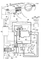
図1は、本発明による車両用空調装置の一実施の形態を示す概略構成図である。
【0017】
まず、構成を説明する。
図1において、コンプレッサ31は、エンジンルームに設けられ、コンプレッサクラッチがONならばエンジン201で駆動され、OFFならばエンジンと切り離されて停止する。
【0018】
冷媒流路切換手段としての四方弁73には、コンプレッサ31の吐出側と車室外熱交換器38と第2の車室内熱交換器33とコンプレッサ31の吸入側が接続され、暖房設定時には、実線示のような流路切り換え状態となり、コンプレッサ31の吐出側と第2の車室内熱交換器33および車室外熱交換器38とコンプレッサ31の吸入側がそれぞれ連通する一方、冷房設定時には、点線示のような流路切り換え状態となり、コンプレッサ31の吐出側と車室外熱交換器38および第2の車室内熱交換器33とコンプレッサ31の吸入側がそれぞれ連通する。
【0019】
車室外熱交換器38は車室外に設けられ、コンプレッサ31から吐出される冷媒の熱を外気に放熱する車室外コンデンサになっている。
【0020】
第1の車室内熱交換器35と第2の車室内熱交換器33は、ダクト39内に配置される。第1の車室内熱交換器35の一端はコンプレッサ31の冷媒吸入に、他端は膨張手段としての膨張弁34に接続し、コンプレッサ31が運転しているときには、常に吸熱器となってブロワファン37によって送風された空気を冷却する。
【0021】
第2の車室内熱交換器33の一端は四方弁73に接続し、他端は逆止弁71に接続する。四方弁73が暖房側に設定されたときには、第2の車室内熱交換器33が放熱器となる状態となって暖房運転が行なわれ、四方弁73が冷房側に設定されたときには、第2の車室内熱交換器33に冷媒が流れない状態となって冷房運転が行なわれる。逆止弁70は、四方弁73が暖房側に設定されたときに、第2の車室内熱交換器33で凝縮された冷媒が車室外熱交換器38に流入することを阻止する。
【0022】
また、ダクト39には、第2の車室内熱交換器33の下流にヒータコア202が設けられ、エンジン冷却水が流入する。203は、エンジン冷却水配管である。
【0023】
ダクト39の第1の車室内熱交換器35よりも上流側には、車室内空気を導入する内気導入口40と、走行風圧を受けて外気を導入する外気導入口41とが設けられている。この内気導入口40と外気導入口41とが分岐する部分には、内気導入口40と外気導入口41とを任意の比率で開閉するインテークドア42が設けられている。インテークドア42の開度たるインテークドア開度Xintは、外気導入量がゼロでフル内気となる位置をXint=0%と設定し、フル外気導入となる位置をXint=100%と設定する。内気導入口40と外気導入口41との空気導入側(空気流の下流側)と第1の車室内熱交換器35との間には、ブロワファン37が配置され、制御装置43で駆動されるブロワファンモータ44で回転駆動されるようになっている。
【0024】
第2の車室内熱交換器33の下流側には、エアミックスドア46が設けられている。このエアミックスドア46は、制御装置43で駆動される図外のエアミックスドアアクチュエータにより、下流のヒータコア202を通過する空気と通過しない空気の割合を調節するように開閉する。エアミックスドア46は、ヒータコア通過風量を可変することができ、ヒータ風量可変手段となっている。エアミックスドア46の開度たるエアミックスドア開度Xmixは、エアミックスドア46が一点鎖線示の位置となってヒータコア202を通過する空気がゼロとなるときをXmix=0%(全閉、Full COOL)と設定し、エアミックスドア46が二点鎖線示の位置となってすべての空気がヒータコア202を通過するときをXmix=100%(全開、Full HOT)と設定する。
【0025】
ダクト39のヒータコア202よりも下流側には、上記冷風と温風との混合を良くすることにより、温度調節された空調風を作る部屋としてのエアミックスチャンバ47が設けられている。エアミックスチャンバ47には、図外の対象乗員の上半身に向けて空調風を吹き出すベンチレータ吹出口51と、対象乗員の足元に向けて空調風を吹き出すフット吹出口53と、図外のフロントウィンドガラスに向けて空調風を吹き出すデフロスタ吹出口52とが設けられている。エアミックスチャンバ47内には、ベンチレータドア55とフットドア57とデフロスタドア56とが設けられている。ベンチレータドア55は、制御装置43で駆動される図外のベンチレータドアアクチュエータにより、ベンチレータ吹出口51を開閉する。フットドア57は、制御装置43で駆動される図外のフットドアアクチュエータにより、フット吹出口53を開閉する。デフロスタドア56は、制御装置43で駆動される図外のデフロスタドアアクチュエータにより、デフロスタ吹出口52を開閉する。デフロスタドア56は、デフロスタ吹出風量を可変することができ、デフロスタ風量可変手段となっている。デフロスタドア56の開度たるデフロスタドア開度Xdefは、デフロスタ吹出口52が全閉となる位置をXdef=0%と設定し、デフロスタ吹出口52が全開となる位置をXdef=100%と設定する。
【0026】
制御装置43は、第1の車室内熱交換器作動温度センサ59と日射量センサ61と外気温センサ62と室温センサ63と室温設定器64と吹出口モードスイッチ65とブロワファンスイッチ66とエンジン冷却水温センサ204などの熱環境情報入力手段から得られる第1の車室内熱交換器35の作動温度Tevaと、車両の日射量Qsunと、車室外の外気温度Tambと、車室内の検出温度(車室内温度)Troomと、車室内の設定温度Tptcと、水温Twなどの熱環境情報により、エアミックスドア開度Xmixとインテークドア開度Xintとデフロスタドア開度Xdefと風量Vevaと目標吹出温度Tofなどの目標冷暖房条件を演算し、車室内の冷暖房条件が上記演算された目標冷暖房条件を維持するように、ブロワファンモータ44とインテークドアアクチュエータとエアミックスドアアクチュエータとベンチレータドアアクチュエータとフットドアアクチュエータとデフロスタドアアクチュエータなどを駆動する。
【0027】
また、制御装置43は、車室内の暖房要求があるときに、エンジン水温と第1設定水温および第2設定水温を比較してエアコンサイクルによる暖房運転の作動非作動を選択する第1暖房制御手段や第2暖房制御手段の役割を果たしたり、必要に応じてコンプレッサクラッチをON/OFFを行なう制御手段となっている。
【0028】
エンジン制御装置206はエンジン201の制御装置で、スロットル開度センサ207、車速センサ208、エンジン回転数センサ209、走行モードセンサ210等から各センサ認識値を入力し、車両が所定のエンジン停止可能状態にあるか否かを判断する車両状態判断手段となっている。
【0029】
またエンジン制御装置206は、制御装置43にエンジン停止可能不可能の車両状態信号を出力し、制御装置43からコンプレッサ作動要求信号を入力し、車両状態およびコンプレッサ作業要求に応じて、エンジン201の作動非作動を制御するエンジン制御手段の役割も果たしている。
【0030】
また、エンジン制御装置206は、電動ウォータポンプ205の作動非作動制御を行なう。エンジン201が非作動で、車室内から暖房要求がある場合には、電動ウォータポンプを作動させて、エンジン温水をヒータ202に循環させる。
【0031】
第1の車室内熱交換器作動温度センサ59は、第1の車室内熱交換器35の作動状態を検出する第1作動状態検出手段となっている。
【0032】
なお、実際の車両では、車室外熱交換器38の後にラジエータが設けられ、ここにもエンジン冷却水が流れて外気に放熱するようになっているが、図1には図示されていない。また、本実施の形態では、加熱手段としてエンジン冷却水を利用したヒータコアを例にして説明するが、電気ヒータや燃焼式ヒータ等の加熱手段を用いてもよい。
【0033】
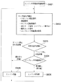
図8は、本実施の形態のエンジンの作動非作動制御の制御フローを示している。
ステップS801でエンジンの作動非作動制御を開始すると、ステップS802では、各センサ値を検出する。スロットル開度センサ207からはスロットル開度を検出し、車速センサ208からは車速を検出し、エンジン回転数センサ209からはエンジン回転数を検出し、走行モードセンサ210からはエンジン走行状態かモータ走行状態かといった走行状態を検出し、制御装置43からはコンプレッサ作動要求信号を取り込む。
【0034】
ステップS803では、ステップS802で検出したセンサ値の少なくとも1つあるいは複数に基づいて、車両が加速走行状態にあるのか、定常走行状態にあるのか、減速走行状態にあるのか、停車状態にあるのかといった車両状態を判断し、所定の条件に照らし合わせてエンジン停止可能状態と判断した場合にはステップS804に進み、エンジン停止不可能状態と判断した場合にはステップS805に進む。
【0035】
ステップS804では、さらに、制御装置43からコンプレッサ作動要求があるか否かを判断し、コンプレッサ作動要求がある場合にはステップS805に進み、コンプレッサ作動要求がない場合にはステップS806に進む。
【0036】
ステップS805ではエンジンを作動状態に設定し、一方、ステップS806ではエンジンを非作動状態に設定して、再びステップS802に戻り、上述のエンジン作動非作動制御を繰り返す。
【0037】
図9〜図13は、本実施の形態のエアコン運転時の制御フローを示している。ステップS901でエアコン運転を開始すると、ステップS902では、各センサ値およびアクチュエータ出力を検出する。ここで、Tptcは設定温度、Twはエンジン水温、Tevaは第1の車室内熱交換器35の作動温度、Tambは外気温、Ticは室温、Qsunは日射量、Vfanはブロワファン電圧、Xdefはデフロスタドア開度、Xintはインテークドア開度、Xmixはエアミックスドア開度、Pevaは第1の車室内熱交換器35の作動圧力、車両状態信号はエンジン制御装置206から取り込むエンジン停止可能不可能に関する信号である。
【0038】
ステップS903では、ステップS902で検出したセンサ値に基づいて目標吹出温度Tofを演算する。
【0039】
ステップS904では、ステップS903で演算した目標吹出温度Tofに基づいて、冷房運転を行なうのか暖房運転を行なうのかを選択し、冷房運転を行なう場合には図11のステップS1101に進み、暖房運転を行なう場合には図10のステップS1001に進む。
【0040】
ステップS1001では、ステップS902でエンジン制御装置206から取り込んだ車両状態信号から、エンジン停止可能状態かエンジン停止不可能状態かを判断し、エンジン停止可能状態の場合にはステップS1002に進み、エンジン停止不可能状態の場合にはステップS1005に進む。一般的なハイブリッド車であれば、減速走行時および停車時がエンジン停止可能状態で、加速走行時および低速走行時がエンジン停止不可能状態となる。また、一般的なアイドルストップ車であれば、停車時がエンジン停止可能状態で、加速走行時と低速走行状態と減速走行状態がエンジン停止不可能状態となる。
【0041】
エンジン停止可能状態ならば、ステップS1002において、制御定数Tw.onにT1℃、制御定数Tw.offにT1+α℃を設定し、ステップS1003の判断を経た後、ステップS1201に進む。ここで、設定温度T1は、車室内の暖房要求度に応じて設定される温度である。
【0042】
ステップS1003では、エンジン停止不可能状態からエンジン停止可能状態に移行した直後か否かを判断し、移行直後ならばステップS1004に進んでエアコンサイクルによる暖房運転状態を暖房運転非作動に設定した後、ステップS1201に進み、そうでない場合にはそのままステップS1201に進む。
【0043】
一方、エンジン停止不可能状態ならば、ステップS1005において、制御定数Tw.onにT2℃、制御定数Tw.offにT2+β℃を設定した後、ステップS1301に進む。
【0044】
ここで、ステップS1002の制御定数T1とステップS1005の制御定数T2の間に、T1<T2なる関係が成り立つようにT1とT2を設定する。
【0045】
ステップS1101では、冷房運転時のコンプレッサの作動非作動を選択する。冷房運転時は第1の車室内熱交換器35の作動温度Tevaを用いて、Teva<3℃ならばコンプレッサ非作動、Teva>4.5℃ならばコンプレッサ作動となるようにコンプレッサの作動非作動を選択する。
【0046】
ステップS1102では、インテークドア開度を目標吹出温度Tofに基づいて演算されるインテークドア開度Xintに設定する。
【0047】
ステップS1103では、ミックスドア開度を目標吹出温度Tofに基づいて演算されるミックスドア開度Xmixに設定する。
【0048】
ステップS1104では、ブロワファン電圧を目標吹出温度Tofに基づいて演算されるブロワファン電圧Vfanに設定する。
【0049】
ステップS1105では、吹出モードを目標吹出温度Tofに基づいて選択される吹出モードに設定した後、再びステップS902に戻り、エアコン運転時の制御を繰り返す。
【0050】
ステップS1201では、ステップS1002で設定した制御定数Tw.onとTw.offに基づいて、エアコンサイクルによる暖房運転の作動非作動を選択する。
【0051】
ステップS1202では、ステップS1201でエアコンサイクルによる暖房運転の作動が選択された場合にはステップS1203に進み、エアコンサイクルによる暖房運転の非作動が選択された場合にはステップS1205に進む。車両状態から見るとエンジンを作動する必要はないが、エンジン水温が設定温度T1よりも低下した場合には、所定のエンジン水温に上昇するまで、ステップS1203やステップS1204の条件で、エンジンの作動とエアコンサイクルによる暖房運転の作動を行なう。
【0052】
ステップS1203では、第1の車室内熱交換器35の作動温度Tevaに基づいて、コンプレッサの作動非作動を選択する。ここで、制御定数Teva.onやTeva.offは外気温や日射量や室温等の車両の熱環境条件およびコンプレッサ31の信頼作動条件を考慮して設定する。なお、ここでは第1の車室内熱交換器35の作動温度Tevaを用いてコンプレッサ作動非作動を選択したが、図14に示すように第1の車室内熱交換器35の作動圧力Pevaを用いてもよい。
【0053】
ステップS1204では、車室内への外気導入量を減らすために、インテークドア開度を予め設定した開度Xint.setに設定する。
【0054】
一方、ステップS1201でエアコンサイクルによる暖房運転の非作動が選択された場合には、ステップS1205でコンプレッサ非作動に設定する。
【0055】
ステップS1206では、少なくとも外気温に基づいてガラスの防曇限界温度Tfineを演算する。図15は、外気温Tambとガラスの防曇限界温度Tfineの関係の一例を示している。このように外気温や日射の有無によって設定温度を変えることができる。
【0056】
ステップS1207では、第1の車室内熱交換器35の作動温度Tevaとガラスの防曇限界温度Tfineを比較し、Teva<TfineならばステップS1204に進み、Teva≧TfineならばステップS1208に進む。
【0057】
ステップS1208では、インテークドアをフル外気導入または乗員のスイッチ操作に応じた状態に設定する。
【0058】
減速走行時や停車時のようなエンジン停止可能な走行状態では、エンジンの作動非作動は、図8に示すように、コンプレッサ31の作動非作動にリンクして行なわれる。そして、コンプレッサ31の作動は、ステップS1201〜S1208に示すように、エンジン水温が設定温度T1よりも低く、かつ、第1の車室内熱交換器35の作動温度Tevaが所定の温度Teva.onよりも高い場合のみ選択される。エアコンサイクルによる暖房運転は、車室内への外気導入量を減らしながら除湿暖房を行なうので、暖房運転時はより短時間でエンジン水温を所定の温度まで上昇させることができるので、エンジン水温が低下した後のエンジン運転時間を短くすることができる。また、除湿暖房時は第1の車室内熱交換器35が低温に維持されるので、コンプレッサ31を非作動にした後もその冷熱を利用することでステップS1207の条件が満たされる間は外気導入量を減らしてもガラスの防曇維持が可能になる。これによってコンプレッサ非作動時の水温低下が緩やかになるので、その分エンジン停止時間が長くなる。このように、エアコンサイクルによる暖房運転作動時にはエンジン運転時間が短くなるとともに、エアコンサイクルによる暖房運転非作動時にはエンジン停止時間が長くなるので、エンジンの運転頻度(運転率)は小さくなる。
【0059】
ステップS1209では、ミックスドア開度を目標吹出温度Tofに基づいて演算されるミックスドア開度Xmixに設定する。
【0060】
ステップS1210では、ブロワファン電圧を目標吹出温度Tofに基づいて演算されるブロワファン電圧Vfanに設定する。
【0061】
ステップS1211では、吹出モードを目標吹出温度Tofに基づいて選択される吹出モードに設定した後、再びステップS902に戻り、エアコン運転時の制御を繰り返す。
【0062】
ステップS1301では、ステップS1005で設定した制御定数Tw.onとTw.offに基づいて、エアコンサイクルによる暖房運転の作動非作動を選択する。
【0063】
ステップS1302では、ステップS1301でエアコンサイクルによる暖房運転の作動が選択された場合にはステップS1303に進み、エアコンサイクルによる暖房運転の非作動が選択された場合にはステップS1305に進む。車両はエンジン走行状態にあるが、何らかの理由によりエンジン発熱が少なくエンジン水温が低い場合には、ステップS1303やステップS1304の条件で、エアコンサイクルによる暖房運転を作動させることでエンジン水温を設定温度T2よりも高い状態に維持する。
【0064】
ステップS1303では、第1の車室内熱交換器35の作動温度Tevaに基づいて、コンプレッサ31の作動非作動を選択する。ここで、制御定数Teva.onやTeva.offは外気温や日射量や室温等の車両の熱環境条件およびコンプレッサ31の信頼作動条件を考慮して設定する。なお、ここでは第1の車室内熱交換器35の作動温度Tevaを用いてコンプレッサ作動非作動を選択したが、図14に示すように第1の車室内熱交換器35の作動圧力Pevaを用いてもよい。
【0065】
ステップS1304では、車室内への外気導入量を減らすために、インテークドア開度を予め設定した開度Xint.setに設定する。
【0066】
一方、ステップS1301でエアコンサイクルによる暖房運転の非作動が選択された場合には、エンジン走行時のエンジン発熱によって十分エンジン水温が高く、エアコンサイクルによる暖房運転は必要ないので、ステップS1305でコンプレッサ非作動に設定する。
【0067】
ステップS1306では、インテークドアをフル外気導入または乗員のスイッチ操作に応じた状態に設定する。
【0068】
ステップS1307では、ミックスドア開度を目標吹出温度Tofに基づいて演算されるミックスドア開度Xmixに設定する。
【0069】
ステップS1308では、ブロワファン電圧を目標吹出温度Tofに基づいて演算されるブロワファン電圧Vfanに設定する。
【0070】
ステップS1309では、吹出モードを目標吹出温度Tofに基づいて選択される吹出モードに設定した後、再びステップS902に戻り、エアコン運転時の制御を繰り返す。
【0071】
図2〜図7は、別のエアコンサイクル構成を示している。
図2に示すエアコンサイクルは、図1に示すエアコンサイクルにおいて、第2の車室内熱交換器33の一端(暖房時の出口側、冷房時の入口側)と逆止弁70の下流を絞り74と二方弁75を介してバイパス路100で接続している。冷房運転時に二方弁75を開閉すると、二方弁開状態では第1の車室内熱交換器35と第2の車室内熱交換器33の両方が蒸発器となり、二方弁閉状態では第1の車室内熱交換器35のみが蒸発器となるので、車室内の冷房負荷に応じて車室内蒸発器の吸熱能力を可変することができる。暖房運転時には、第1の車室内熱交換器35が蒸発器、第2の車室内熱交換器33が凝縮器となる。
【0072】
図3に示すエアコンサイクルは、図1に示すエアコンサイクルにおいて、第2の車室内熱交換器33の一端(暖房時の出口側)と、膨張弁34と第1の車室内熱交換器35の間を絞り80を介してバイパス路100で接続している。冷房運転時は、第1の車室内熱交換器35と第2の車室内熱交換器33の両方が蒸発器となり、暖房運転時は、第1の車室内熱交換器35が蒸発器、第2の車室内熱交換器33が凝縮器となる。
【0073】
図4に示すエアコンサイクルは、図1に示すエアコンサイクルにおいて、第1の車室内熱交換器35と第2の車室内熱交換器33の配置を変えた場合で、冷房運転時は、第1の車室内熱交換器35が蒸発器となり、暖房運転時は、第1の車室内熱交換器35が蒸発器、第2の車室内熱交換器33が凝縮器となる。
【0074】
図5に示すエアコンサイクルは、図1に示すエアコンサイクルにおいて、1つの車室内熱交換器101を第1の冷媒パス77と第2の冷媒パス76で構成した場合で、冷房運転時には、第1の冷媒パス77が蒸発部となり、暖房運転時には、第1の冷媒パス77が蒸発部、第2の冷媒パス76が凝縮部となる。
【0075】
図6に示すエアコンサイクルは、図3に示すエアコンサイクルにおいて、四方弁73の代わりに電磁弁81〜83を用いた場合のエアコンサイクル構成を示している。
【0076】
図7に示すエアコンサイクルは、図1に示すエアコンサイクルにおいて、絞り手段111を追加して、第2の車室内熱交換器33が冷房運転時に蒸発器、暖房運転時に凝縮器となるようにした場合のエアコンサイクル構成を示している。第1の車室内熱交換器35は冷房運転時も暖房運転時も蒸発器となり、冷房運転時には絞り手段111で減圧された後にさらに絞り弁34で減圧された低温冷媒が流入し、暖房運転時には絞り弁34で減圧された低温冷媒が流入する。なお、冷房運転時には、絞り手段111をバイパスさせて第2の車室内熱交換器33を凝縮器、第1の車室内熱交換器35を蒸発器としても良いし、あるいは、絞り弁34をバイパスさせて絞り手段111で減圧された低温冷媒が第1の車室内熱交換器35と第2の車室内熱交換器33の両方に流入するようにしても良い。
【0077】
本実施の形態では、図1に示す車両用空調装置を例にして説明したが、図2〜図7に示すエアコンサイクル、あるいは、これらを組み合わせたエアコンサイクルにおいても同様の効果が得られる。
【0078】
また、本実施の形態では、フロントのみにエアコンを備えた場合を例にして説明したが、フロントとリアにエアコンを備えた場合にも同様の効果を得ることができる。
【0079】
【発明の効果】
所定の運転条件でエンジンの作動を停止するハイブリッド車やアイドルストップ車においては、エンジン停止不可能時は、燃費率のいい状態で走行のためにエンジンが常に運転され、しかもエアコンサイクルによる暖房運転時のコンプレッサ駆動負荷が小さいので、エアコンサイクルによる暖房運転を付加しても、エンジン運転時間は変わらず燃費悪化も小さい。これに対して、エンジン停止可能時は、車室内の暖房やコンプレッサ作動のためにエンジンを作動させるので、できるだけエンジン運転時間を短くしなければ燃費向上は望めない。
【0080】
本発明の車両用空調装置によれば、車両の走行状態がエンジン停止不可能状態にあればエンジン水温が低下した場合にエアコンサイクルによる暖房運転が行なわれて、エンジン水温は常に第2設定水温よりも高い状態に維持される。そして、車両の走行状態がエンジン停止可能状態に移行した後は、エアコンサイクルによる暖房運転が選択されたときのみコンプレッサ作動のためにエンジンを作動する。エアコンサイクルによる暖房運転を行なうことで、従来よりも少ないヒータ放熱量で同等以上のヒータ能力を得ることができるので、所定のエンジン水温まで上昇させるためのエンジン運転時間を短くすることが可能になり、エンジンの燃費向上が図られる。
【0081】
また、第1設定水温を第2設定水温よりも低い温度に設定することで、車両の走行状態がエンジン停止不可能状態からエンジン停止可能状態に移行した直後には、より長時間エアコンサイクルによる暖房運転の非作動が選択されることになるので、エンジン停止時間を長くすることが可能になる。また、第1設定温度を低くすることで、エンジン本体から周囲に放熱される熱量が減少するので、所定のエンジン水温まで上昇させるためのエンジン運転時間をさらに短くして燃費向上を図ることができる。
【0082】
また、車両がエンジン停止可能状態にあり、エンジン水温と第1設定水温を比較しながらエアコンサイクルによる暖房運転の作動非作動を選択する場合において、エアコンサイクルによる暖房運転非作動が選択されたときには、外気状態と第1の車室内熱交換器の作動状態から判断してガラスの防曇維持が可能な範囲で車室内への外気導入量を減少させるので、この間のエンジン水温低下が緩やかになり、エアコンサイクルによる暖房運転の非作動時の時間を長くすることができ、燃費向上に貢献できる。
【0083】
また、第1設定水温にヒステリシスを設け、車両がエンジン停止不可能状態からエンジン停止可能状態に移行した直後には、ヒステリシス内でエアコンサイクルによる暖房運転の非作動を優先するので、車両がエンジン停止不可能状態からエンジン停止可能状態に移行した直後に、エンジン非作動が選択される確率を高くすることが可能になる。これによってエアコン運転時においても、減速走行時の一部や停車時にエンジンを非作動にするという車両の特徴を堅持することができる。
【図面の簡単な説明】
【図1】本発明による車両用空調装置の一実施の形態の概略構成図である。
【図2】本発明による車両用空調装置の別のエアコンサイクル構成図である。
【図3】本発明による車両用空調装置の別のエアコンサイクル構成図である。
【図4】本発明による車両用空調装置の別のエアコンサイクル構成図である。
【図5】本発明による車両用空調装置の別のエアコンサイクル構成図である。
【図6】本発明による車両用空調装置の別のエアコンサイクル構成図である。
【図7】本発明による車両用空調装置の別のエアコンサイクル構成図である。
【図8】エンジンの作動非作動制御の制御フローである。
【図9】エアコン制御の制御フローである。
【図10】エアコン制御の制御フローである。
【図11】エアコン制御の制御フローである。
【図12】エアコン制御の制御フローである。
【図13】エアコン制御の制御フローである。
【図14】作動圧力Pevaによるコンプレッサ作動非作動の選択の関係を示す図である。
【図15】外気温に対する防曇限界温度の変化の関係を示す図である。
【符号の説明】
31 コンプレッサ
33 第2の車室内熱交換器
34 膨張弁
35 第1の車室内熱交換器
37 ブロワファン
38 車室外熱交換器
39 ダクト
40 内気導入口
41 外気導入口
42 インテークドア
43 制御装置
44 ブロワファンモータ
46 エアミックスドア
47 エアミックスチャンバ
51 ベンチレータ吹出口
52 デフロスタ吹出口
53 フット吹出口
55 ベンチレータドア
56 デフロスタドア
57 フットドア
59 第1の車室内熱交換器作動温度センサ
61 日射量センサ
62 外気温センサ
63 室温センサ
64 室温設定器
65 吹出口モードスイッチ
66 ブロワファンスイッチ
70,71 逆止弁
73 四方弁
74 絞り
75 二方弁
76 第2の冷媒パス
77 第1の冷媒パス
80 絞り
81,82,83 電磁弁
100 バイパス路
101 室内熱交換器
111 絞り手段
201 エンジン
202 ヒータコア
203 エンジン冷却水配管
204 エンジン冷却水温センサ
205 電動ウォータポンプ
206 エンジン制御装置
207 スロットル開度センサ
208 車速センサ
209 エンジン回転数センサ
210 走行モードセンサ[0001]
BACKGROUND OF THE INVENTION
The present invention relates to a vehicle air conditioner, and more particularly to a vehicle air conditioner provided with a vapor compression cycle that circulates refrigerant to an exterior heat exchanger and an interior heat exchanger by driving a compressor.
[0002]
[Prior art]
In general, a vehicle equipped with an engine uses engine cooling water as a heat source for an air conditioner. However, in the hybrid vehicle and the idle stop vehicle, there is a problem that the engine is not operated when the motor is running if the vehicle is a hybrid vehicle and the engine is not operated when the vehicle is idle if the vehicle is an idle stop vehicle. On the other hand, for example, an air conditioner disclosed in Japanese Patent Laid-Open No. 9-233601 is known as an air conditioner for a vehicle that can obtain a necessary and sufficient heating performance while minimizing engine operation. Yes.
[0003]
When there is a request for heating in the passenger compartment, the room temperature and the engine water temperature are detected, the temperature difference ΔT between the set temperature of the air conditioner and the room temperature is compared with a determination value T based on the engine water temperature, and ΔT ≧ T If so, the engine is operated, and if ΔT <T, the engine is stopped.
[0004]
[Problems to be solved by the invention]
Hybrid vehicles and idle-stop vehicles are equipped with smaller and more efficient engines than conventional equivalent-class vehicles. For this reason, there is a high demand for heating in the passenger compartment, and at low outside temperatures where the amount of heat released from the engine to the outside air increases, once the engine water temperature drops, the water temperature rises very slowly even if the engine is operated. It took a long time to reach the engine water temperature of the engine, and as a result, there was a problem that improvement in fuel consumption could not be expected by stopping the engine.
[0005]
As one means for solving such a problem, development of a method using an air conditioner cycle capable of dehumidifying and heating operation is desired. An air conditioning cycle that can be dehumidified and heated reduces both the amount of outside air introduced into the passenger compartment at low outside temperatures, while maintaining both heating performance and glass anti-fogging, so even if the outside air temperature decreases or the engine heat generation decreases. The engine water temperature can be raised to a predetermined temperature in a short time while maintaining high heater performance.
[0006]
The present invention extends the initial engine stop time by entering a predetermined operating state such as deceleration, motor running or stopping while maintaining a high engine water temperature and a high dehumidifying capacity, and dehumidifying heating after the subsequent decrease in the engine water temperature. An object of the present invention is to provide a vehicle air conditioner that can increase the engine water temperature to a predetermined temperature in a shorter time using the characteristics of a possible air conditioner cycle.
[0007]
[Means for Solving the Problems]
In order to solve the above-described problems, the present invention provides a vehicle air conditioner according to a first aspect of the present invention, comprising: a compressor driven by an engine; and a refrigerant flow path that switches a refrigerant flow between cooling operation and heating operation. Heat exchange between the switching means, the vehicle exterior heat exchanger that exchanges heat between the refrigerant and the outside air, the expansion means that adiabatically expands the refrigerant, and the conditioned air that blows out into the passenger compartment, and acts as an evaporator during heating operation An air conditioner cycle comprising a first vehicle interior heat exchanger and a second vehicle interior heat exchanger acting as a condenser, and water temperature detection means for detecting the engine water temperature At least one of the throttle opening signal, the vehicle speed signal, the engine speed signal, and the driving mode signal is used to determine whether the vehicle is in a predetermined engine stoppable state from the driving state. Vehicle condition determining means, engine control means for operating / deactivating the engine based on at least a determination result of the vehicle condition determining means and a compressor operation request for the air conditioner cycle, and a vehicle room heating request When the state determination means determines that the vehicle is in a state where the engine can be stopped, the engine water temperature detected by the water temperature detection means is compared with the first set water temperature, and the heating operation by the air conditioning cycle is performed. When there is a first heating control means for selecting non-operation, and the vehicle state determination means determines that the vehicle is not in a predetermined engine stoppable state when there is a heating request in the vehicle interior, the water temperature detection means Heating operation by the air conditioning cycle so that the detected engine water temperature does not fall below the second set water temperature And a second heating control means for selecting the operation.
[0008]
According to a second aspect of the present invention, in the vehicle air conditioner according to the first aspect, the first set water temperature is set to a temperature lower than the second set water temperature.
[0009]
According to a third aspect of the present invention, in the vehicle air conditioner according to the first aspect, the outside air state detecting means for detecting the state of the outside air and the operating state of the first vehicle interior heat exchanger are as follows. First operating state detecting means for detecting, and when the non-operation of the heating operation by the air-conditioner cycle is selected by the first heating control means, the state of the outside air and the first vehicle interior heat exchanger Judging from the operating state, the amount of outside air introduced into the passenger compartment is varied within a range where the defogging of the glass can be maintained.
[0010]
According to a fourth aspect of the present invention, in the vehicle air conditioner according to the third aspect of the present invention, a hysteresis is provided in the first set water temperature so that the vehicle changes from a predetermined engine stop impossible state to an engine stop possible state. When it is determined that it is immediately after the transition, priority is given to the non-operation of the heating operation by the air conditioning cycle within the hysteresis.
[0011]
Hereinafter, the operation of the present invention will be described.
According to the first aspect of the present invention, in a hybrid vehicle or an idle stop vehicle equipped with an engine that does not operate according to the traveling state of the vehicle and the compressor operation request of the air conditioner cycle, if the traveling state of the vehicle is in an engine stoppable state The engine water temperature is compared with the first set water temperature to select whether the heating operation by the air-conditioning cycle is inactive or not, so that the engine water temperature does not fall below the second set water temperature if the vehicle is in a state where the engine cannot be stopped. Select whether to activate or deactivate heating operation by the air conditioning cycle.
[0012]
As a result, if the running state of the vehicle is in a state where the engine cannot be stopped, the engine water temperature is always kept higher than the second set water temperature because the heating operation by the air-conditioner cycle is performed when the engine water temperature decreases. After the vehicle running state shifts to the engine stoppable state, the engine is operated for the compressor operation only when the heating operation by the air conditioner cycle is selected. Therefore, the required engine operation time in the engine stoppable state is shortened. It becomes possible to do.
[0013]
According to the second invention, the first set water temperature is set to a temperature lower than the second set water temperature.
As a result, immediately after the running state of the vehicle shifts from the state in which the engine cannot be stopped to the state in which the engine can be stopped, the non-operation of the heating operation by the air conditioner cycle is selected for a longer time. It becomes possible to do. Moreover, since the amount of heat radiated from the engine body to the surroundings is reduced by lowering the first set temperature, it is possible to shorten the engine operation time for raising the temperature to a predetermined engine water temperature.
[0014]
According to the third aspect of the present invention, when the vehicle is in a state where the engine can be stopped and the operation / non-operation of the heating operation by the air-conditioning cycle is selected while comparing the engine water temperature and the first set water temperature, the heating operation / non-operation by the air-conditioning cycle is selected. Is selected, the amount of outside air introduced into the vehicle interior is varied within a range in which the defogging of the glass can be maintained as judged from the outside air state and the operating state of the first vehicle interior heat exchanger.
As a result, the amount of outside air introduced into the passenger compartment decreases within a range where the glass can be kept anti-fogged when the engine is not in operation, so that the engine water temperature can be gradually lowered during this period.
[0015]
According to the fourth aspect of the invention, the first set water temperature is provided with hysteresis, and immediately after the vehicle shifts from the engine non-stoppable state to the engine stoppable state, priority is given to the non-operation of the heating operation by the air conditioner cycle within the hysteresis. .
As a result, it is possible to increase the probability that the engine non-operation is selected immediately after the vehicle shifts from the engine stop impossible state to the engine stop possible state.
[0016]
DETAILED DESCRIPTION OF THE INVENTION
Hereinafter, an embodiment of a vehicle air conditioner according to the present invention will be described in detail with reference to the accompanying drawings.
FIG. 1 is a schematic configuration diagram showing an embodiment of a vehicle air conditioner according to the present invention.
[0017]
First, the configuration will be described.
In FIG. 1, the
[0018]
The four-
[0019]
The vehicle
[0020]
The first vehicle
[0021]
One end of the second vehicle
[0022]
Further, the
[0023]
On the upstream side of the first vehicle
[0024]
An
[0025]
On the downstream side of the
[0026]
The
[0027]
Further, the
[0028]
The
[0029]
The
[0030]
Further, the
[0031]
The first vehicle interior heat exchanger
[0032]
In an actual vehicle, a radiator is provided after the passenger
[0033]
FIG. 8 shows a control flow of the operation non-operation control of the engine of the present embodiment.
When engine operation / non-operation control is started in step S801, each sensor value is detected in step S802. The throttle
[0034]
In step S803, based on at least one or more of the sensor values detected in step S802, whether the vehicle is in an accelerated traveling state, a steady traveling state, a decelerating traveling state, or a stopped state. If the vehicle state is determined and it is determined that the engine can be stopped in light of predetermined conditions, the process proceeds to step S804. If it is determined that the engine cannot be stopped, the process proceeds to step S805.
[0035]
In step S804, it is further determined whether or not there is a compressor operation request from the
[0036]
In step S805, the engine is set to an operating state. On the other hand, in step S806, the engine is set to a non-operating state, and the process returns to step S802 again to repeat the above-described engine operation non-operating control.
[0037]
9 to 13 show a control flow during the air conditioner operation of the present embodiment. When the air conditioner operation is started in step S901, each sensor value and actuator output are detected in step S902. Here, Tptc is the set temperature, Tw is the engine water temperature, Teva is the operating temperature of the first vehicle
[0038]
In step S903, the target blowing temperature Tof is calculated based on the sensor value detected in step S902.
[0039]
In step S904, it is selected whether to perform the cooling operation or the heating operation based on the target outlet temperature Tof calculated in step S903. When performing the cooling operation, the process proceeds to step S1101 in FIG. 11 to perform the heating operation. In this case, the process proceeds to step S1001 in FIG.
[0040]
In step S1001, it is determined from the vehicle state signal captured from the
[0041]
If the engine can be stopped, the control constant Tw. on, T1 ° C., control constant Tw. T1 + α ° C. is set to off, and after the determination in step S1003, the process proceeds to step S1201. Here, the set temperature T1 is a temperature set in accordance with the degree of heating requirement in the passenger compartment.
[0042]
In step S1003, it is determined whether or not it is immediately after the transition from the engine stop impossible state to the engine stop possible state. If it is immediately after the transition, the process proceeds to step S1004 and the heating operation state by the air conditioner cycle is set to the heating operation non-operation. The process proceeds to step S1201, and if not, the process proceeds to step S1201 as it is.
[0043]
On the other hand, if the engine cannot be stopped, in step S1005, the control constant Tw. on, T2 ° C., control constant Tw. After setting T2 + β ° C. to off, the process proceeds to step S1301.
[0044]
Here, T1 and T2 are set so that a relationship of T1 <T2 is established between the control constant T1 in step S1002 and the control constant T2 in step S1005.
[0045]
In step S1101, the operation / non-operation of the compressor during the cooling operation is selected. During cooling operation, using the operating temperature Teva of the first vehicle
[0046]
In step S1102, the intake door opening is set to the intake door opening Xint calculated based on the target outlet temperature Tof.
[0047]
In step S1103, the mix door opening is set to the mix door opening Xmix calculated based on the target outlet temperature Tof.
[0048]
In step S1104, the blower fan voltage is set to the blower fan voltage Vfan calculated based on the target blowing temperature Tof.
[0049]
In step S1105, after setting the blowing mode to the blowing mode selected based on the target blowing temperature Tof, the process returns to step S902 again, and the control during the air conditioner operation is repeated.
[0050]
In step S1201, the control constant Tw. on and Tw. Based on the off, the operation / non-operation of the heating operation by the air conditioner cycle is selected.
[0051]
In step S1202, if the heating operation by the air conditioning cycle is selected in step S1201, the process proceeds to step S1203, and if the non-operation of the heating operation by the air conditioning cycle is selected, the process proceeds to step S1205. When viewed from the vehicle state, it is not necessary to operate the engine. However, when the engine water temperature falls below the set temperature T1, the engine operation is performed under the conditions of step S1203 and step S1204 until the engine water temperature rises to a predetermined engine water temperature. The heating operation by the air conditioning cycle is performed.
[0052]
In step S1203, based on the operating temperature Teva of the first vehicle
[0053]
In step S1204, in order to reduce the amount of outside air introduced into the vehicle interior, the opening Xint. Set to set.
[0054]
On the other hand, when the non-operation of the heating operation by the air conditioner cycle is selected in step S1201, the compressor is set to non-operation in step S1205.
[0055]
In step S1206, the antifogging limit temperature Tfine of the glass is calculated based on at least the outside air temperature. FIG. 15 shows an example of the relationship between the outside air temperature Tamb and the antifogging limit temperature Tfine of the glass. In this way, the set temperature can be changed depending on the outside air temperature and the presence or absence of solar radiation.
[0056]
In step S1207, the operating temperature Teva of the first
[0057]
In step S1208, the intake door is set to a state corresponding to full outside air introduction or a passenger's switch operation.
[0058]
In a traveling state in which the engine can be stopped, such as when the vehicle is decelerating or stopped, the engine is deactivated and linked to the operation of the
[0059]
In step S1209, the mix door opening is set to the mix door opening Xmix calculated based on the target outlet temperature Tof.
[0060]
In step S1210, the blower fan voltage is set to the blower fan voltage Vfan calculated based on the target blowing temperature Tof.
[0061]
In step S1211, after setting the blowing mode to the blowing mode selected based on the target blowing temperature Tof, the process returns to step S902 again, and the control during the air conditioner operation is repeated.
[0062]
In step S1301, the control constant Tw. on and Tw. Based on the off, the operation / non-operation of the heating operation by the air conditioner cycle is selected.
[0063]
In step S1302, if the heating operation by the air conditioning cycle is selected in step S1301, the process proceeds to step S1303. If the non-operation of the heating operation by the air conditioning cycle is selected, the process proceeds to step S1305. Although the vehicle is in an engine running state, if for some reason the engine heat is low and the engine water temperature is low, the engine water temperature is set to a temperature higher than the set temperature T2 by operating the heating operation by the air conditioner cycle under the conditions of step S1303 and step S1304. Also keep it high.
[0064]
In step S1303, the operation / non-operation of the
[0065]
In step S1304, in order to reduce the amount of outside air introduced into the vehicle compartment, the opening Xint. Set to set.
[0066]
On the other hand, when the non-operation of the heating operation by the air conditioner cycle is selected in step S1301, the engine water temperature is sufficiently high due to the engine heat generated during the engine running, and the heating operation by the air conditioner cycle is not necessary. Set to.
[0067]
In step S1306, the intake door is set to a state corresponding to full outside air introduction or a passenger's switch operation.
[0068]
In step S1307, the mix door opening is set to the mix door opening Xmix calculated based on the target outlet temperature Tof.
[0069]
In step S1308, the blower fan voltage is set to the blower fan voltage Vfan calculated based on the target blowing temperature Tof.
[0070]
In step S1309, after setting the blowing mode to the blowing mode selected based on the target blowing temperature Tof, the process returns to step S902 again, and the control during the air conditioner operation is repeated.
[0071]
2 to 7 show other air-conditioner cycle configurations.
The air conditioner cycle shown in FIG. 2 is the same as the air conditioner cycle shown in FIG. 1 except that one end of the second vehicle interior heat exchanger 33 (the outlet side during heating, the inlet side during cooling) and the downstream of the
[0072]
The air conditioner cycle shown in FIG. 3 is the same as the air conditioner cycle shown in FIG. 1 except that one end (exit side during heating) of the second vehicle
[0073]
The air conditioner cycle shown in FIG. 4 is a case where the arrangement of the first vehicle
[0074]
The air conditioner cycle shown in FIG. 5 is a case where one vehicle
[0075]
The air conditioner cycle shown in FIG. 6 shows an air conditioner cycle configuration in which
[0076]
The air conditioner cycle shown in FIG. 7 is the same as the air conditioner cycle shown in FIG. 1 except that the throttle means 111 is added so that the second vehicle
[0077]
In the present embodiment, the vehicle air conditioner shown in FIG. 1 has been described as an example, but the same effect can be obtained in the air conditioner cycle shown in FIGS.
[0078]
Further, in the present embodiment, the case where the air conditioner is provided only at the front has been described as an example, but the same effect can be obtained also when the air conditioner is provided at the front and rear.
[0079]
【The invention's effect】
In hybrid vehicles and idle stop vehicles that stop the engine operation under specified operating conditions, when the engine cannot be stopped, the engine is always operated for driving with a good fuel efficiency, and during heating operation by an air-conditioning cycle Since the compressor driving load is small, even if heating operation by an air-conditioner cycle is added, the engine operation time does not change and fuel consumption deterioration is small. On the other hand, when the engine can be stopped, the engine is operated for heating the interior of the vehicle and operating the compressor. Therefore, fuel consumption cannot be improved unless the engine operation time is shortened as much as possible.
[0080]
According to the vehicle air conditioner of the present invention, if the running state of the vehicle is in the state where the engine cannot be stopped, the heating operation is performed by the air-conditioning cycle when the engine water temperature decreases, and the engine water temperature is always higher than the second set water temperature. Is maintained at a high level. Then, after the vehicle running state shifts to the engine stoppable state, the engine is operated for the compressor operation only when the heating operation by the air conditioner cycle is selected. By performing heating operation using the air conditioner cycle, it is possible to obtain the same or higher heater capacity with a smaller amount of heat released from the heater than before, so it is possible to shorten the engine operation time for raising the engine water temperature to a predetermined level. The fuel consumption of the engine is improved.
[0081]
In addition, by setting the first set water temperature to a temperature lower than the second set water temperature, heating by the air conditioner cycle for a longer period of time immediately after the vehicle running state shifts from the engine stop impossible state to the engine stop possible state. Since non-operation of operation is selected, the engine stop time can be lengthened. Moreover, since the amount of heat radiated from the engine body to the surroundings is reduced by lowering the first set temperature, the engine operating time for raising the engine temperature to a predetermined engine water temperature can be further shortened to improve fuel efficiency. .
[0082]
Further, when the vehicle is in a state where the engine can be stopped and the operation / non-operation of the heating operation by the air-conditioning cycle is selected while comparing the engine water temperature and the first set water temperature, the heating operation non-operation by the air-conditioning cycle is selected, Judging from the outside air state and the operating state of the first vehicle interior heat exchanger, the amount of outside air introduced into the vehicle interior is reduced within a range where the defogging of the glass can be maintained. The time when the heating operation by the air-conditioning cycle is not operated can be lengthened, which contributes to the improvement of fuel consumption.
[0083]
In addition, the first set water temperature is provided with hysteresis. Immediately after the vehicle shifts from the state in which the engine cannot be stopped to the state in which the engine can be stopped, priority is given to the non-operation of the heating operation by the air conditioner cycle within the hysteresis. Immediately after shifting from the impossible state to the engine stop possible state, it is possible to increase the probability that the engine non-operation is selected. As a result, it is possible to maintain the characteristics of the vehicle such that the engine is deactivated when the vehicle is operating at a reduced speed or when the vehicle is stopped.
[Brief description of the drawings]
FIG. 1 is a schematic configuration diagram of an embodiment of a vehicle air conditioner according to the present invention.
FIG. 2 is another air conditioning cycle configuration diagram of the vehicle air conditioner according to the present invention.
FIG. 3 is another air conditioning cycle configuration diagram of the vehicle air conditioner according to the present invention.
FIG. 4 is another air conditioning cycle configuration diagram of the vehicle air conditioner according to the present invention.
FIG. 5 is another air conditioning cycle configuration diagram of the vehicle air conditioner according to the present invention.
FIG. 6 is another air conditioning cycle configuration diagram of the vehicle air conditioner according to the present invention.
FIG. 7 is another air conditioning cycle configuration diagram of the vehicle air conditioner according to the present invention.
FIG. 8 is a control flow of engine non-operation control.
FIG. 9 is a control flow of air conditioner control.
FIG. 10 is a control flow of air conditioner control.
FIG. 11 is a control flow of air conditioner control.
FIG. 12 is a control flow of air conditioner control.
FIG. 13 is a control flow of air conditioner control.
FIG. 14 is a diagram showing a relationship of selection of non-operation of the compressor according to the operating pressure Peva.
FIG. 15 is a diagram showing the relationship of changes in the anti-fogging limit temperature with respect to the outside air temperature.
[Explanation of symbols]
31 Compressor
33 Second vehicle interior heat exchanger
34 Expansion valve
35 First vehicle interior heat exchanger
37 Blower Fan
38 Outside heat exchanger
39 Duct
40 Inside air inlet
41 Outside air inlet
42 Intake door
43 Controller
44 Blower fan motor
46 Air Mix Door
47 Air Mix Chamber
51 Ventilator outlet
52 Defroster outlet
53 Foot outlet
55 Ventilator door
56 Defroster door
57 Foot door
59 First cabin heat exchanger operating temperature sensor
61 Solar radiation sensor
62 Outside air temperature sensor
63 Room temperature sensor
64 Room temperature setting device
65 Air outlet mode switch
66 Blower fan switch
70, 71 check valve
73 Four-way valve
74 Aperture
75 Two way valve
76 Second refrigerant path
77 First refrigerant path
80 aperture
81, 82, 83 Solenoid valve
100 Bypass
101 Indoor heat exchanger
111 Aperture means
201 engine
202 Heater core
203 Engine cooling water piping
204 Engine coolant temperature sensor
205 Electric water pump
206 Engine control device
207 Throttle opening sensor
208 Vehicle speed sensor
209 Engine speed sensor
210 Travel mode sensor
Claims (4)
冷房運転と暖房運転で冷媒流れを切り換える冷媒流路切換手段と、
冷媒と外気とで熱交換する車室外熱交換器と、
冷媒を断熱膨張させる膨張手段と、
冷媒と車室内に吹き出す空調風とで熱交換し、暖房運転時に、蒸発器として作用する第1の車室内熱交換器と、凝縮器として作用する第2の車室内熱交換器とで構成される車室内熱交換器とから成るエアコンサイクルと、
エンジン水温を検出する水温検出手段と、
少なくともスロットル開度信号と車速信号とエンジン回転数信号と走行モード信号の中の1つの信号あるいは複数の信号を用いて、車両の走行状態から所定のエンジン停止可能状態にあるか否かを判断する車両状態判断手段と、
少なくとも前記車両状態判断手段の判断結果と前記エアコンサイクルのコンプレッサ作動要求から、前記エンジンを作動非作動させるエンジン制御手段と、
車室内の暖房要求があるときに、前記車両状態判断手段により車両が所定のエンジン停止可能状態にあると判断された状態では、前記水温検出手段により検出されるエンジン水温と第1設定水温とを比較して、前記エアコンサイクルによる暖房運転の作動非作動を選択する第1暖房制御手段と、
車室内の暖房要求があるときに、前記車両状態判断手段により車両が所定のエンジン停止可能状態にないと判断された状態では、前記水温検出手段により検出されるエンジン水温が第2設定水温よりも低下しないように前記エアコンサイクルによる暖房運転の作動非作動を選択する第2暖房制御手段と、
を備えることを特徴とする車両用空調装置。A compressor driven by the engine;
A refrigerant flow path switching means for switching the refrigerant flow between the cooling operation and the heating operation;
An exterior heat exchanger that exchanges heat between the refrigerant and the outside air;
Expansion means for adiabatic expansion of the refrigerant;
It is composed of a first vehicle interior heat exchanger that functions as an evaporator and a second vehicle interior heat exchanger that functions as a condenser during the heating operation by exchanging heat between the refrigerant and the conditioned air blown into the vehicle interior. An air conditioner cycle comprising a vehicle interior heat exchanger,
Water temperature detecting means for detecting engine water temperature;
At least one of the throttle opening signal, the vehicle speed signal, the engine speed signal, and the traveling mode signal is used to determine whether or not the vehicle is in a predetermined engine stoppable state from the traveling state of the vehicle. Vehicle state determination means;
Engine control means for operating and deactivating the engine from at least the determination result of the vehicle state determination means and the compressor operation request of the air conditioner cycle;
When there is a request for heating in the passenger compartment, when the vehicle state determination means determines that the vehicle is in a predetermined engine stoppable state, the engine water temperature detected by the water temperature detection means and the first set water temperature are calculated. In comparison, a first heating control means for selecting the operation non-operation of the heating operation by the air conditioning cycle;
When there is a request for heating in the passenger compartment, the engine water temperature detected by the water temperature detecting means is higher than the second set water temperature when the vehicle state determining means determines that the vehicle is not in a predetermined engine stoppable state. Second heating control means for selecting whether the heating operation by the air-conditioning cycle is not activated or not so as not to decrease;
A vehicle air conditioner comprising:
前記第1設定水温を前記第2設定水温よりも低い温度に設定する
ことを特徴とする車両用空調装置。In the vehicle air conditioner according to claim 1,
The vehicle air conditioner characterized in that the first set water temperature is set to a temperature lower than the second set water temperature.
外気の状態を検出する外気状態検出手段と、前記第1の車室内熱交換器の作動状態を検出する第1作動状態検出手段とを設けるとともに、
前記第1暖房制御手段により前記エアコンサイクルによる暖房運転の非作動が選択された場合に、外気の状態と前記第1の車室内熱交換器の作動状態から判断してガラスの防曇維持が可能な範囲で車室内への外気導入量を可変する
ことを特徴とする車両用空調装置。In the vehicle air conditioner according to claim 1,
An outside air state detecting means for detecting the state of the outside air and a first operating state detecting means for detecting the operating state of the first vehicle interior heat exchanger are provided,
When the non-operation of the heating operation by the air-conditioning cycle is selected by the first heating control means, it is possible to maintain the defogging of the glass by judging from the outside air state and the operating state of the first vehicle interior heat exchanger. A vehicle air conditioner characterized in that the amount of outside air introduced into the passenger compartment can be varied within a wide range.
前記第1設定水温にヒステリシスを設け、車両が所定のエンジン停止不可能状態からエンジン停止可能状態に移行した直後であると判断されたときには、ヒステリシス内では前記エアコンサイクルによる暖房運転の非作動を優先する
ことを特徴とする車両用空調装置。In the vehicle air conditioner according to claim 1,
When the first set water temperature is provided with hysteresis, and it is determined that the vehicle has just shifted from the predetermined state where the engine cannot be stopped to the state where the engine can be stopped, priority is given to the non-operation of the heating operation by the air conditioner cycle within the hysteresis. An air conditioner for a vehicle.
Priority Applications (1)
| Application Number | Priority Date | Filing Date | Title |
|---|---|---|---|
| JP12600599A JP3726552B2 (en) | 1999-05-06 | 1999-05-06 | Air conditioner for vehicles |
Applications Claiming Priority (1)
| Application Number | Priority Date | Filing Date | Title |
|---|---|---|---|
| JP12600599A JP3726552B2 (en) | 1999-05-06 | 1999-05-06 | Air conditioner for vehicles |
Publications (2)
| Publication Number | Publication Date |
|---|---|
| JP2000313223A JP2000313223A (en) | 2000-11-14 |
| JP3726552B2 true JP3726552B2 (en) | 2005-12-14 |
Family
ID=14924380
Family Applications (1)
| Application Number | Title | Priority Date | Filing Date |
|---|---|---|---|
| JP12600599A Expired - Fee Related JP3726552B2 (en) | 1999-05-06 | 1999-05-06 | Air conditioner for vehicles |
Country Status (1)
| Country | Link |
|---|---|
| JP (1) | JP3726552B2 (en) |
Families Citing this family (3)
| Publication number | Priority date | Publication date | Assignee | Title |
|---|---|---|---|---|
| KR101342931B1 (en) * | 2011-03-09 | 2013-12-18 | 한라비스테온공조 주식회사 | Heat pump system for vehicle |
| JP2019162894A (en) * | 2018-03-19 | 2019-09-26 | 株式会社デンソー | Air conditioning unit for vehicle |
| JP7185412B2 (en) * | 2018-03-23 | 2022-12-07 | サンデン株式会社 | Vehicle air conditioner |
-
1999
- 1999-05-06 JP JP12600599A patent/JP3726552B2/en not_active Expired - Fee Related
Also Published As
| Publication number | Publication date |
|---|---|
| JP2000313223A (en) | 2000-11-14 |
Similar Documents
| Publication | Publication Date | Title |
|---|---|---|
| JP5482728B2 (en) | Refrigeration cycle equipment | |
| JPH05229333A (en) | Vehicle heat pump type air conditioner | |
| JP2003279180A (en) | Refrigeration cycle device for vehicles | |
| JP3799768B2 (en) | Refrigeration cycle equipment for vehicles | |
| JP3716686B2 (en) | Air conditioner for vehicles | |
| JP2009166629A (en) | Air conditioner for vehicles | |
| JP3726552B2 (en) | Air conditioner for vehicles | |
| KR20110064380A (en) | Air Conditioning Control Method of Hybrid Vehicle | |
| JP3718935B2 (en) | Air conditioner for vehicles | |
| JPH08216655A (en) | Heat pump type air conditioner for vehicle | |
| JPH05201243A (en) | Heat pump type cooling and heating device for vehicle | |
| JP2000062452A (en) | Vehicle air conditioner | |
| JP3460422B2 (en) | Vehicle air conditioner | |
| JP2003159930A (en) | Vehicle air conditioner | |
| JP7540289B2 (en) | Vehicle air conditioning system | |
| JP3336886B2 (en) | Vehicle air conditioner | |
| JP3458717B2 (en) | Vehicle air conditioner | |
| JP3301265B2 (en) | Heat pump type air conditioner for vehicles | |
| JP3858352B2 (en) | Air conditioner for vehicles | |
| JP3269358B2 (en) | Heat pump type air conditioner for vehicles | |
| JP3267147B2 (en) | Vehicle air conditioner | |
| JP4303190B2 (en) | Manual air conditioner | |
| JP2564906B2 (en) | Automotive air conditioners | |
| JP3368801B2 (en) | Vehicle air conditioner | |
| JP2025033680A (en) | Vehicle air conditioning system |
Legal Events
| Date | Code | Title | Description |
|---|---|---|---|
| A977 | Report on retrieval |
Free format text: JAPANESE INTERMEDIATE CODE: A971007 Effective date: 20050809 |
|
| TRDD | Decision of grant or rejection written | ||
| A01 | Written decision to grant a patent or to grant a registration (utility model) |
Free format text: JAPANESE INTERMEDIATE CODE: A01 Effective date: 20050906 |
|
| A61 | First payment of annual fees (during grant procedure) |
Free format text: JAPANESE INTERMEDIATE CODE: A61 Effective date: 20050919 |
|
| R150 | Certificate of patent or registration of utility model |
Free format text: JAPANESE INTERMEDIATE CODE: R150 |
|
| FPAY | Renewal fee payment (event date is renewal date of database) |
Free format text: PAYMENT UNTIL: 20091007 Year of fee payment: 4 |
|
| FPAY | Renewal fee payment (event date is renewal date of database) |
Free format text: PAYMENT UNTIL: 20101007 Year of fee payment: 5 |
|
| LAPS | Cancellation because of no payment of annual fees |