JP3724552B2 - Image forming apparatus - Google Patents
Image forming apparatus Download PDFInfo
- Publication number
- JP3724552B2 JP3724552B2 JP2000021286A JP2000021286A JP3724552B2 JP 3724552 B2 JP3724552 B2 JP 3724552B2 JP 2000021286 A JP2000021286 A JP 2000021286A JP 2000021286 A JP2000021286 A JP 2000021286A JP 3724552 B2 JP3724552 B2 JP 3724552B2
- Authority
- JP
- Japan
- Prior art keywords
- paper
- discharge
- image
- roller
- paddle
- Prior art date
- Legal status (The legal status is an assumption and is not a legal conclusion. Google has not performed a legal analysis and makes no representation as to the accuracy of the status listed.)
- Expired - Fee Related
Links
- 238000005452 bending Methods 0.000 claims 1
- 238000004140 cleaning Methods 0.000 description 6
- 108091008695 photoreceptors Proteins 0.000 description 4
- 238000010586 diagram Methods 0.000 description 3
- 238000000034 method Methods 0.000 description 3
- 230000015572 biosynthetic process Effects 0.000 description 2
- 238000007599 discharging Methods 0.000 description 2
- 230000037303 wrinkles Effects 0.000 description 2
- 230000000694 effects Effects 0.000 description 1
- 238000012986 modification Methods 0.000 description 1
- 230000004048 modification Effects 0.000 description 1
- 230000002093 peripheral effect Effects 0.000 description 1
- 238000000926 separation method Methods 0.000 description 1
- 239000000758 substrate Substances 0.000 description 1
- 238000004804 winding Methods 0.000 description 1
Images


Classifications
-
- B—PERFORMING OPERATIONS; TRANSPORTING
- B65—CONVEYING; PACKING; STORING; HANDLING THIN OR FILAMENTARY MATERIAL
- B65H—HANDLING THIN OR FILAMENTARY MATERIAL, e.g. SHEETS, WEBS, CABLES
- B65H2404/00—Parts for transporting or guiding the handled material
- B65H2404/10—Rollers
- B65H2404/11—Details of cross-section or profile
- B65H2404/111—Details of cross-section or profile shape
- B65H2404/1114—Paddle wheel
Landscapes
- Delivering By Means Of Belts And Rollers (AREA)
Description
【0001】
【発明の属する技術分野】
本発明は、複写機、プリンタ、ファクシミリ等の画像形成装置において、画像が形成された用紙を排紙トレイに排出する技術に関する。
【0002】
【従来の技術】
画像形成装置においては、例えば、回転駆動される感光体と、この感光体上に静電潜像を形成する潜像形成手段と、前記静電潜像をトナー像に現像する現像手段と、トナー像を用紙に転写する転写装置と、給紙カセットから用紙を1枚づつ転写装置に供給するための給紙装置を備え、転写装置により画像が形成された用紙を排紙トレイに排出するようにしている。
【0003】
画像が形成された用紙は、排出部に設けられた排出ローラ対により排紙トレイに排出されるが、用紙の後端が排出ローラ対のニップ部を離れた瞬間、用紙への搬送力が消失するため、用紙の後端が排出ローラ対に残らないように用紙の後端を跳ね飛ばす必要がある。そのために、従来、図5に示すように、駆動ローラ51aと従動ローラ51bからなる排出ローラ51において、駆動ローラ51aの軸中心に対して放射状に延びる複数の羽根状のパドル52aを有する排出パドル52を設け、パドル52aにより用紙Sの後端を跳ね飛ばすようにしている(例えば特開平7−223765号公報)。
【0004】
【発明が解決しようとする課題】
しかしながら、上記従来のパドル52aの形状は、駆動ローラ51aの軸中心に対して放射状に延びているため、駆動ローラ51aと従動ローラ51bのニップ部において、パドル52aが用紙Sに直角方向に突き上げる力が作用し、薄紙ではパドル52aの突き上げによりシワが生じ、OHPシートでは画像ムラ(いわゆるパドル跡)が発生するという問題を有している。特に、反転排出方式においては画像面にパドルが接することになり、画像面のトナーを擦ったり、OHPシートのオイル面を擦りオイルムラとなって画像が乱れてしまうという問題を有している。
【0005】
本発明は、上記従来の問題を解決するものであって、用紙排出部において用紙のシワの発生や画像の乱れを防止することができる画像形成装置を提供することを目的とする。
【0006】
【課題を解決するための手段】
上記目的を達成するために、本発明の画像形成装置は、画像が形成された用紙を排出ローラ(29a)と排出パドル(33)により排紙トレイに排出する画像形成装置において、前記排出パドル(33)は、排出ローラの駆動軸(30)に固定される基体(33b)と、該基体(33b)の外周に形成された複数のパドル(33a)を備え、前記パドル(33a)の先端を前記駆動軸(30)の回転方向(R)と逆方向に折曲して形成されていることを特徴とする。
以上
【0007】
【発明の実施の形態】
以下、本発明の実施の形態を図面を参照しつつ説明する。図1は、本発明が適用される画像形成装置の1例を示す全体構成図である。この画像形成装置は、4色のトナーによりフルカラー画像を形成することができるカラー電子写真プリンタであるが、本発明はこれに限定されるものではなく、複写機、ファクシミリ等の画像形成装置の全てに適用可能である。
【0008】
画像形成装置1はケース本体2を備え、ケース本体2内に感光体3が配設され、図示しない駆動手段によって図示矢印方向に回転駆動される。この感光体3の周囲には、その回転方向に沿って、帯電手段としての帯電ローラ4、感光体3上に静電潜像を形成するための露光ユニット5、静電潜像を現像するための現像器ユニット6、感光体3上に形成されたトナー像を中間転写ベルト7上に転写するための中間転写装置9、感光体3上に残留するトナーを除去するためのクリーニング装置10が配置されている。
【0009】
現像器ユニット6は、イエロー用現像器6Y、シアン用現像器6C、マゼンタ用現像器6Mおよびブラック用現像器6Kからなり、各現像器は、現像ハウジング6a内に配設された現像ローラ6bを備えている。そして、これらの現像器6Y、6C、6M、6Kはそれぞれ感光体3に対して揺動可能に配設され、感光体3の1回転毎に選択的に一つの現像器の現像ローラ6bのみが感光体3に当接可能にされている。
【0010】
中間転写装置9は、中間転写ベルト7を走行させるための駆動ローラ11、感光体3上のトナー像を中間転写ベルト7に転写するための一次転写ローラ(一次転写部)12、中間転写ベルト上のトナー像を用紙に転写するための二次転写ローラ(二次転写部)13、中間転写ベルト上のトナーを除去するためのクリーニング装置14等から構成されている。二次転写ローラ13およびクリーニング装置14は、中間転写ベルト7から離接可能にされている。
【0011】
ケース本体2内には用紙束が収納される給紙カセット15が配設され、ケース本体2の側面には薄紙やOHPシート等の特殊用紙を供給するための給紙トレイ16が設けられ、また、ケース本体2の上部には画像が転写された用紙を収容する排紙トレイ17が設けられ、給紙カセット15および給紙トレイ16と排紙トレイ17との間に用紙搬送路19が形成されている。用紙搬送路19の二次転写部13の下流側には定着装置20が配設され、また、排紙トレイ17に向かう用紙排出口27には排出手段29が設けられている。なお、21は両面印刷のための用紙搬送路である。
【0012】
給紙カセット15および給紙トレイ16の用紙排出部には、用紙束に圧接するようにピックアップローラ22が設けられ、ピックアップローラ22に近接してその下流側に捌き機構23が配設されている。また、捌き機構の下流側には一対のスキュー補正ローラ24が設けられ、スキュー補正ローラ24の下流側に一対のレジストローラ25が配設されている。なお、26は、給紙カセット15側からの用紙を搬送する搬送ローラである。
【0013】
上記構成からなる画像形成装置の作用について説明する。図示しないコンピュータからの画像形成信号が入力されると、感光体3が回転駆動され、先ず、感光体3の表面が帯電ローラ4によって一様に帯電され、一様に帯電された感光体3の表面に、露光ユニット5によって第1色目(例えばイエロー)の画像情報に応じた選択的な露光Lがなされ、イエローの静電潜像が形成される。
【0014】
感光体3には、イエロー用現像器6Yの現像ローラ6bのみが接触し、これによってイエローの静電潜像のトナー像が感光体3上に形成される。中間転写ベルト7には上記トナーの帯電極性と逆極性の一次転写電圧が印加され、感光体3上に形成されたトナー像が、一次転写部12において中間転写ベルト7上に転写される。このとき、二次転写ローラ13およびクリーニング装置14は、中間転写ベルト7から退避されている。感光体3上に残留しているトナーはクリーニング装置10によって除去された後、感光体3の表面は除電手段(図示せず)により除電される。
【0015】
上記の動作が画像形成信号の第2色目、第3色目、第4色目に対応して、感光体3と中間転写ベルト7の1回転による潜像形成、現像、転写が繰り返され、前記画像形成信号の内容に応じた4色のトナー像が中間転写ベルト7上において重ね会わされて転写される。そして、このフルカラー画像が二次転写部13に達するタイミングで、レジストローラ25が駆動し用紙が用紙搬送路19を経て二次転写部13に供給され、このとき、転写ローラ13が中間転写ベルト7に当接されるとともに二次転写電圧が印加され、中間転写ベルト7上のフルカラー像が用紙上に転写される。用紙上に転写された画像は定着装置20により定着され、用紙は排出手段29により排紙トレイ17に排紙され、中間転写ベルト7上のトナー像はクリーニング装置14により除去される。
【0016】
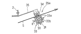
図2および図3は、本発明の1実施形態を示し、図2は図1の用紙排出手段を示し図3のX−X線に沿う断面図、図3は図2の平面図である。
【0017】
排出手段29(図1)は、排紙トレイ17に回動可能に装着された駆動軸30を備え、駆動軸30には複数の駆動ローラ31が固定されるとともに、駆動ローラ31の間に用紙に腰をつけて搬送するための補助ローラ32が固定され、さらに中央部に本発明に係わる排出パドル33が固定されている。駆動ローラ31の上面には、駆動ローラ31の回転摩擦により回動される従動ローラ34が圧接され、駆動ローラ31と従動ローラ34により排出ローラ29aを構成している。各従動ローラ34は、板バネ35により回動自在に支持され、板バネ35はケース本体2に固定されている。なお、前記各ローラ31、32、33、34はゴム等の弾性部材からなっている。
【0018】
排出パドル33は、駆動軸30に固定された基体33bと、基体33bの外周接線方向に延びる複数の羽根状のパドル33aを備え、パドル33aは駆動軸30の回転方向Rと逆方向に延びるように形成されている。なお、パドル33aの先端は駆動ローラ31の外周から突出する長さに設定されている。
【0019】
上記構成からなる本発明の作用について説明する。転写部13において上面に画像が形成された用紙Sは、用紙排出部27に設けられた排出手段29により画像が反転(下面)されて排紙トレイ17に排出される。用紙Sの後端が駆動ローラ31と従動ローラ34のニップ部を離れた瞬間、用紙Sへの搬送力が消失するが、このとき、排出パドル33のパドル33aにより用紙Sの後端を跳ね飛ばすようにしている。本発明においてパドル33aが駆動軸30の回転方向Rと逆方向且つ接線方向に延びるように形成されているため、パドル33aが用紙Sに滑らかに接し直角方向に突き上げる力が作用しなくなり、シワの発生を防止することができ、また、反転排出方式において画像面のトナーを擦することを防止でき、さらに、OHPシートにおける画像ムラ(いわゆるパドル跡)が発生するという問題や、OHPシートのオイル面を擦りオイルムラとなって画像が乱れてしまうという問題を解消することができる。
【0020】
図4は、本発明の他の実施形態を示す排出パドル33の側面図である。上記実施形態においては、パドル33aを基体33bの外周接線方向に延びるように形成しているが、本実施形態においては、パドル33aの先端を回転方向Rと逆方向に折曲させるようにしている。
【0021】
以上、本発明の実施の形態について説明したが、本発明はこれに限定されるものではなく種々の変更が可能である。例えば、上記実施形態においては、一つの排出パドル33を駆動軸30の中央部に設けているが、中央部に限定されるものではなく、また、排出パドルを複数設けるようにしてもよい。
【0022】
【発明の効果】
以上の説明から明らかなように本発明によれば、用紙排出部において用紙の後端を跳ね飛ばして排紙トレイにスタックする場合に、用紙のシワの発生や画像の乱れを防止しつつ円滑かつ確実に用紙を排出することができる。
【図面の簡単な説明】
【図1】本発明が適用される画像形成装置の1例を示す全体構成図である。
【図2】本発明の1実施形態で図1の用紙排出手段を示し図3のX−X線に沿う断面図である。
【図3】図2の平面図である。
【図4】本発明の他の実施形態を示す側面図である。
【図5】従来の用紙排出手段を説明するための図である。
【符号の説明】
29…排出手段
29a…排出ローラ
30…駆動軸
33…排出パドル
33a…パドル
33b…基体
R…回転方向[0001]
BACKGROUND OF THE INVENTION
The present invention relates to a technique for discharging a sheet on which an image is formed to a discharge tray in an image forming apparatus such as a copying machine, a printer, or a facsimile.
[0002]
[Prior art]
In the image forming apparatus, for example, a rotationally driven photoconductor, a latent image forming unit that forms an electrostatic latent image on the photoconductor, a developing unit that develops the electrostatic latent image into a toner image, and toner The image forming apparatus includes a transfer device that transfers an image to paper and a paper feed device that supplies the paper from the paper feed cassette to the transfer device one by one, and discharges the paper on which the image has been formed by the transfer device to a paper discharge tray. ing.
[0003]
The paper on which the image is formed is discharged to the paper discharge tray by a pair of discharge rollers provided in the discharge section. However, at the moment when the rear end of the paper leaves the nip portion of the pair of discharge rollers, the conveyance force to the paper disappears. Therefore, it is necessary to jump off the trailing edge of the sheet so that the trailing edge of the sheet does not remain on the discharge roller pair. Therefore, conventionally, as shown in FIG. 5, in the
[0004]
[Problems to be solved by the invention]
However, since the shape of the
[0005]
SUMMARY OF THE INVENTION An object of the present invention is to solve the above-described conventional problems, and to provide an image forming apparatus capable of preventing generation of paper wrinkles and image disturbance in a paper discharge unit.
[0006]
[Means for Solving the Problems]
In order to achieve the above object, an image forming apparatus according to the present invention is an image forming apparatus that discharges a sheet on which an image is formed to a discharge tray by a discharge roller (29a) and a discharge paddle (33). 33) includes a base (33b) which is fixed to the drive shaft of the discharge roller (30), comprising said substrate (s paddles formed on the outer periphery of 33b) (33a), the tip of the paddle (33a) The drive shaft (30) is bent in the direction opposite to the rotation direction (R).
[0007]
DETAILED DESCRIPTION OF THE INVENTION
Hereinafter, embodiments of the present invention will be described with reference to the drawings. FIG. 1 is an overall configuration diagram showing an example of an image forming apparatus to which the present invention is applied. This image forming apparatus is a color electrophotographic printer capable of forming a full color image with four color toners. However, the present invention is not limited to this, and all image forming apparatuses such as copying machines and facsimiles can be used. It is applicable to.
[0008]
The image forming apparatus 1 includes a case
[0009]
The developing
[0010]
The
[0011]
A
[0012]
A
[0013]
The operation of the image forming apparatus having the above configuration will be described. When an image forming signal from a computer (not shown) is input, the photoconductor 3 is rotationally driven. First, the surface of the photoconductor 3 is uniformly charged by the charging roller 4, and the uniformly charged photoconductor 3 is charged. The
[0014]
Only the developing
[0015]
In response to the second color, the third color, and the fourth color of the image formation signal, the above operation is repeated to form a latent image, develop, and transfer by one rotation of the photosensitive member 3 and the intermediate transfer belt 7, and the image formation is performed. Four color toner images corresponding to the signal contents are superimposed and transferred on the intermediate transfer belt 7. Then, at the timing when this full-color image reaches the
[0016]
2 and 3 show an embodiment of the present invention. FIG. 2 is a sectional view taken along line XX of FIG. 3 showing the paper discharge means of FIG. 1, and FIG. 3 is a plan view of FIG.
[0017]
The discharge means 29 (FIG. 1) includes a
[0018]
The
[0019]
The operation of the present invention having the above configuration will be described. The sheet S on which the image is formed on the upper surface in the
[0020]
FIG. 4 is a side view of the
[0021]
Although the embodiment of the present invention has been described above, the present invention is not limited to this, and various modifications are possible. For example, in the above-described embodiment, one
[0022]
【The invention's effect】
As is apparent from the above description, according to the present invention, when the trailing edge of the paper is bounced off in the paper discharge unit and stacked on the paper discharge tray, the paper is smoothly and reliably prevented from wrinkling and image disturbance. The paper can be reliably discharged.
[Brief description of the drawings]
FIG. 1 is an overall configuration diagram showing an example of an image forming apparatus to which the present invention is applied.
2 is a cross-sectional view taken along the line XX of FIG. 3, showing the paper discharge means of FIG. 1 in one embodiment of the present invention.
FIG. 3 is a plan view of FIG. 2;
FIG. 4 is a side view showing another embodiment of the present invention.
FIG. 5 is a diagram for explaining a conventional paper discharge unit.
[Explanation of symbols]
29 ... discharge means 29a ... discharge
Claims (1)
Priority Applications (1)
| Application Number | Priority Date | Filing Date | Title |
|---|---|---|---|
| JP2000021286A JP3724552B2 (en) | 2000-01-31 | 2000-01-31 | Image forming apparatus |
Applications Claiming Priority (1)
| Application Number | Priority Date | Filing Date | Title |
|---|---|---|---|
| JP2000021286A JP3724552B2 (en) | 2000-01-31 | 2000-01-31 | Image forming apparatus |
Publications (2)
| Publication Number | Publication Date |
|---|---|
| JP2001206605A JP2001206605A (en) | 2001-07-31 |
| JP3724552B2 true JP3724552B2 (en) | 2005-12-07 |
Family
ID=18547711
Family Applications (1)
| Application Number | Title | Priority Date | Filing Date |
|---|---|---|---|
| JP2000021286A Expired - Fee Related JP3724552B2 (en) | 2000-01-31 | 2000-01-31 | Image forming apparatus |
Country Status (1)
| Country | Link |
|---|---|
| JP (1) | JP3724552B2 (en) |
Families Citing this family (3)
| Publication number | Priority date | Publication date | Assignee | Title |
|---|---|---|---|---|
| JP4305482B2 (en) | 2006-09-08 | 2009-07-29 | ブラザー工業株式会社 | Paper discharge device |
| JP4784674B2 (en) | 2009-03-27 | 2011-10-05 | ブラザー工業株式会社 | Discharging device and document conveying device |
| KR101404733B1 (en) * | 2012-12-18 | 2014-06-09 | 주식회사신도리코 | Apparatus for aligning paper of Finisher Device |
-
2000
- 2000-01-31 JP JP2000021286A patent/JP3724552B2/en not_active Expired - Fee Related
Also Published As
| Publication number | Publication date |
|---|---|
| JP2001206605A (en) | 2001-07-31 |
Similar Documents
| Publication | Publication Date | Title |
|---|---|---|
| JP2010001122A (en) | Paper feeder, image forming device, and paper feed method | |
| JP4932347B2 (en) | Transfer device and image forming apparatus | |
| KR100880474B1 (en) | Image forming apparatus | |
| US20070158895A1 (en) | Image forming apparatus and image forming method, and program | |
| JP3724552B2 (en) | Image forming apparatus | |
| JPH10260616A (en) | Image forming device | |
| JP2005258167A (en) | Cleaning device | |
| JP2003173091A (en) | Image forming device | |
| JP3791588B2 (en) | Image forming apparatus | |
| JP3783763B2 (en) | Paper feeder | |
| JP3712034B2 (en) | Image forming apparatus | |
| US6519438B2 (en) | Tandem type color image forming apparatus having an intermediate transfer belt | |
| JP2022151914A (en) | image forming device | |
| JP3841147B2 (en) | Image forming apparatus | |
| JP2001255778A (en) | Image forming device | |
| JP3714401B2 (en) | Image forming apparatus | |
| JP2001225980A (en) | Paper feeder | |
| JP4408155B2 (en) | Image forming apparatus | |
| JP3685247B2 (en) | Paper feeder | |
| JP2003173090A (en) | Belt-shaped image carrier support device of image forming apparatus | |
| JP2002023454A (en) | Image forming device | |
| JP2004264454A (en) | Image forming device | |
| JP2004203540A (en) | Belt conveyor device | |
| JP3891294B2 (en) | Image forming apparatus | |
| JP3972184B2 (en) | Fixing device |
Legal Events
| Date | Code | Title | Description |
|---|---|---|---|
| A977 | Report on retrieval |
Free format text: JAPANESE INTERMEDIATE CODE: A971007 Effective date: 20050425 |
|
| A131 | Notification of reasons for refusal |
Free format text: JAPANESE INTERMEDIATE CODE: A131 Effective date: 20050427 |
|
| A521 | Written amendment |
Free format text: JAPANESE INTERMEDIATE CODE: A523 Effective date: 20050610 |
|
| RD02 | Notification of acceptance of power of attorney |
Free format text: JAPANESE INTERMEDIATE CODE: A7422 Effective date: 20050610 |
|
| TRDD | Decision of grant or rejection written | ||
| A01 | Written decision to grant a patent or to grant a registration (utility model) |
Free format text: JAPANESE INTERMEDIATE CODE: A01 Effective date: 20050831 |
|
| A61 | First payment of annual fees (during grant procedure) |
Free format text: JAPANESE INTERMEDIATE CODE: A61 Effective date: 20050913 |
|
| R150 | Certificate of patent or registration of utility model |
Free format text: JAPANESE INTERMEDIATE CODE: R150 |
|
| FPAY | Renewal fee payment (event date is renewal date of database) |
Free format text: PAYMENT UNTIL: 20080930 Year of fee payment: 3 |
|
| FPAY | Renewal fee payment (event date is renewal date of database) |
Free format text: PAYMENT UNTIL: 20090930 Year of fee payment: 4 |
|
| FPAY | Renewal fee payment (event date is renewal date of database) |
Free format text: PAYMENT UNTIL: 20090930 Year of fee payment: 4 |
|
| FPAY | Renewal fee payment (event date is renewal date of database) |
Free format text: PAYMENT UNTIL: 20100930 Year of fee payment: 5 |
|
| FPAY | Renewal fee payment (event date is renewal date of database) |
Free format text: PAYMENT UNTIL: 20100930 Year of fee payment: 5 |
|
| FPAY | Renewal fee payment (event date is renewal date of database) |
Free format text: PAYMENT UNTIL: 20110930 Year of fee payment: 6 |
|
| FPAY | Renewal fee payment (event date is renewal date of database) |
Free format text: PAYMENT UNTIL: 20120930 Year of fee payment: 7 |
|
| FPAY | Renewal fee payment (event date is renewal date of database) |
Free format text: PAYMENT UNTIL: 20130930 Year of fee payment: 8 |
|
| S531 | Written request for registration of change of domicile |
Free format text: JAPANESE INTERMEDIATE CODE: R313531 |
|
| R350 | Written notification of registration of transfer |
Free format text: JAPANESE INTERMEDIATE CODE: R350 |
|
| LAPS | Cancellation because of no payment of annual fees |