JP3722017B2 - Optical disk device - Google Patents
Optical disk device Download PDFInfo
- Publication number
- JP3722017B2 JP3722017B2 JP2001190670A JP2001190670A JP3722017B2 JP 3722017 B2 JP3722017 B2 JP 3722017B2 JP 2001190670 A JP2001190670 A JP 2001190670A JP 2001190670 A JP2001190670 A JP 2001190670A JP 3722017 B2 JP3722017 B2 JP 3722017B2
- Authority
- JP
- Japan
- Prior art keywords
- value
- recording power
- default
- recording
- optical disc
- Prior art date
- Legal status (The legal status is an assumption and is not a legal conclusion. Google has not performed a legal analysis and makes no representation as to the accuracy of the status listed.)
- Expired - Fee Related
Links
- 230000003287 optical effect Effects 0.000 title claims description 55
- 238000000034 method Methods 0.000 description 8
- 238000010586 diagram Methods 0.000 description 4
- 230000007274 generation of a signal involved in cell-cell signaling Effects 0.000 description 4
- 238000005457 optimization Methods 0.000 description 3
- 230000001678 irradiating effect Effects 0.000 description 2
- 230000032683 aging Effects 0.000 description 1
- 230000007423 decrease Effects 0.000 description 1
- 230000000694 effects Effects 0.000 description 1
- 239000000284 extract Substances 0.000 description 1
- 229920006395 saturated elastomer Polymers 0.000 description 1
Images


Classifications
-
- G—PHYSICS
- G11—INFORMATION STORAGE
- G11B—INFORMATION STORAGE BASED ON RELATIVE MOVEMENT BETWEEN RECORD CARRIER AND TRANSDUCER
- G11B7/00—Recording or reproducing by optical means, e.g. recording using a thermal beam of optical radiation by modifying optical properties or the physical structure, reproducing using an optical beam at lower power by sensing optical properties; Record carriers therefor
- G11B7/12—Heads, e.g. forming of the optical beam spot or modulation of the optical beam
- G11B7/125—Optical beam sources therefor, e.g. laser control circuitry specially adapted for optical storage devices; Modulators, e.g. means for controlling the size or intensity of optical spots or optical traces
- G11B7/126—Circuits, methods or arrangements for laser control or stabilisation
- G11B7/1267—Power calibration
-
- G—PHYSICS
- G11—INFORMATION STORAGE
- G11B—INFORMATION STORAGE BASED ON RELATIVE MOVEMENT BETWEEN RECORD CARRIER AND TRANSDUCER
- G11B7/00—Recording or reproducing by optical means, e.g. recording using a thermal beam of optical radiation by modifying optical properties or the physical structure, reproducing using an optical beam at lower power by sensing optical properties; Record carriers therefor
- G11B7/12—Heads, e.g. forming of the optical beam spot or modulation of the optical beam
- G11B7/125—Optical beam sources therefor, e.g. laser control circuitry specially adapted for optical storage devices; Modulators, e.g. means for controlling the size or intensity of optical spots or optical traces
- G11B7/126—Circuits, methods or arrangements for laser control or stabilisation
- G11B7/1263—Power control during transducing, e.g. by monitoring
-
- G—PHYSICS
- G11—INFORMATION STORAGE
- G11B—INFORMATION STORAGE BASED ON RELATIVE MOVEMENT BETWEEN RECORD CARRIER AND TRANSDUCER
- G11B7/00—Recording or reproducing by optical means, e.g. recording using a thermal beam of optical radiation by modifying optical properties or the physical structure, reproducing using an optical beam at lower power by sensing optical properties; Record carriers therefor
- G11B7/004—Recording, reproducing or erasing methods; Read, write or erase circuits therefor
- G11B7/0045—Recording
Description
【0001】
【発明の属する技術分野】
本発明は光ディスク装置、特に記録パワーの最適化に関する。
【0002】
【従来の技術】
従来より、CD−R等の記録可能な光ディスク装置ではOPC(Optimum Power Control)と称される記録パワーの最適化処理が実行されている。このOPCでは、記録パワーを複数フレームにおいて複数段、例えば15フレームにおいて15段階に変化させて所定のテストエリアにテストデータを記録し、各テストデータを再生してその信号品質を評価する。再生信号の品質としては、通常β値が用いられる。β値とは、再生RF信号のエンベロープのピーク電圧(A)とボトム電圧(B)からβ=(A+B)/(A−B)により算出されるパラメータであり、この値が所定範囲(例えば0.04〜0.05)の場合に最適とされる。そして、所望のβ値(基準β値)が得られる記録パワーを最適記録パワーとして選択し、以後はこの最適記録パワーでデータを記録する。
【0003】
なお、特開平7−85494号公報には、所望のβ値を下回るβ値と、所望のβ値を上回るβ値を求め、これら2つのβ値の演算により所望のβ値が得られる記録パワーの仮想パワー段を求め、この仮想段に最も近いパワー段を最適記録パワーに設定することが記載されている。
【0004】
【発明が解決しようとする課題】
しかしながら、記録に用いられる光ディスクは種々存在するため、基準となるβ値も種々存在し得る。予め用意されたデフォルトのβ値(例えばβ=0.04)を用いて最適記録パワーを選択することも可能であるが、当然ながら必ずしも最適な記録品質が得られるとは限らず、場合によっては本来の最適β値よりも高めのβ値を基準として記録パワーを設定してしまうため、RF信号が熱波形歪みを生じて再生不能となるおそれもある。
【0005】
なお、光ディスクには固有のディスクIDが予め記録されており、予め光ディスク装置側のテーブルにディスクID毎に基準β値を算出し記憶させておくことも可能であるが、処理が煩雑となる。また、基準β値を記憶していない光ディスクが挿入された場合には対応できない。
【0006】
本発明は、上記従来技術の有する課題に鑑みなされたものであり、その目的は、光ディスク毎に最適な記録パワーを設定してデータを高品質で記録できる装置を提供することにある。
【0007】
【課題を解決するための手段】
上記目的を達成するために、本発明は、記録パワーを変化させて光ディスクにテストデータを記録し、該テストデータの再生信号のβ値が基準β値となる記録パワーを最適記録パワーとしてデータを記録する光ディスク装置であって、デフォルトのβ値を記憶する手段と、前記記録パワーを変化させたときの各記録パワーにおけるβ値を記憶する手段と、前記記録パワー毎のβ値の変化率が所定のしきい値以上となる範囲に前記デフォルトのβ値が含まれるか否かを判定し、前記デフォルトのβ値が前記範囲内に含まれる場合には前記デフォルトのβ値を前記基準β値に設定し、前記デフォルトのβ値が前記範囲内に含まれない場合には前記範囲内に含まれるように新たな基準β値を設定する制御手段とを有することを特徴とする。
【0008】
また、本発明は、記録パワーを変化させて光ディスクにテストデータを記録し、該テストデータの再生信号のβ値が基準β値となる記録パワーを最適記録パワーとしてデータを記録する光ディスク装置であって、デフォルトのβ値を記憶する手段と、前記記録パワーを変化させたときの各記録パワーにおけるβ値を記憶する手段と、前記記録パワー毎のβ値の傾き変化率が所定のしきい値以上となる範囲に前記デフォルトのβ値が含まれるか否かを判定し、前記デフォルトのβ値が前記範囲内に含まれる場合には前記デフォルトのβ値を前記基準β値に設定し、前記デフォルトのβ値が前記範囲内に含まれない場合には前記範囲内に含まれるように新たな基準β値を設定する制御手段とを有することを特徴とする。
【0009】
また、本発明は、記録パワーを変化させて光ディスクにテストデータを記録し、該テストデータの再生信号のβ値が基準β値となる記録パワーを最適記録パワーとしてデータを記録する光ディスク装置であって、デフォルトのβ値を記憶する手段と、前記記録パワーを変化させたときの各記録パワーにおけるβ値を記憶する手段と、前記記録パワー毎のβ値の変化率が所定のしきい値以上となる範囲の上限β値を算出し、前記上限β値と前記デフォルトのβ値とに基づいて前記上限β値と前記デフォルトのβ値との間にある新たな基準β値を設定する制御手段とを有することを特徴とする。
【0010】
また、本発明は、記録パワーを変化させて光ディスクにテストデータを記録し、該テストデータの再生信号のβ値が基準β値となる記録パワーを最適記録パワーとしてデータを記録する光ディスク装置であって、デフォルトのβ値を記憶する手段と、前記記録パワーを変化させたときの各記録パワーにおけるβ値を記憶する手段と、前記記録パワー毎のβ値の傾き変化率が所定のしきい値以上となる範囲の上限β値を算出し、前記上限β値と前記デフォルトのβ値とに基づいて前記上限β値と前記デフォルトのβ値との間にある新たな基準β値を設定する制御手段とを有することを特徴とする。
【0011】
このように、本発明に係る光ディスク装置では、β値等の再生信号品質データの変化自体から基準値を設定する。図5には、記録パワーを変化させたときのβ値の変化の様子が示されている。一般に、記録パワーを増大させるとβ値はほぼ一定の変化率でリニアに増大していくが、記録パワーがある値以上となると熱波形歪みを生じ、β値は小さな変化率で非リニアに変化していく。これは、過剰な熱によりピットの形が歪み、熱が拡散してしまうためと考えられる。したがって、逆に、β値の傾き(すなわち変化率)が一定であれば熱歪みは生じておらず、β値の傾きが小さくなりリニアでなくなった場合には熱歪みが生じて記録パワーとしては不適当であると判定できる。そこで、β値等の変化から熱歪みを生じていない値を選択して基準値とすることで、その光ディスクに合致した最適な基準値を設定でき、これを用いて記録パワーの最適化を図ることができる。
【0012】
本発明では、予めその光ディスクの最適な基準値を検出してディスクID等に記録しておく必要がなく、かつ、光ディスク毎に最適記録パワーを設定できる。
【0013】
【発明の実施の形態】
以下、図面に基づき本発明の実施形態について説明する。
【0014】
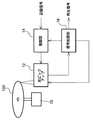
図1には、本実施形態に係る光ディスク装置の要部構成図が示されている。光ディスク装置は、光ピックアップ部12、制御部14及び信号処理部16を含んで構成される。
【0015】
光ピックアップ部12は、スピンドルモータ10で回転駆動される光ディスク100にレーザ光を照射して記録及び再生を行う。記録用の駆動信号は制御部14から供給され、光ディスク100に3T〜11Tのピットを形成することでデータを記録する。また、再生パワーのレーザ光を照射してその反射光から得られる再生RF信号を信号処理部16に出力する。
【0016】
信号処理部16は、入力したRF信号を復調し再生データとして出力する。復調は、フィルタによりノイズを除去した後、イコライザ及びPLL回路でクロックを生成して行われる。また、信号処理部16は、反射光からトラッキングエラー信号やフォーカスエラー信号を抽出し、光ピックアップ部12にサーボ信号を出力する。
【0017】
制御部14は、記録信号に基づいて光ピックアップ部12内のLD(レーザダイオード)を駆動するための駆動信号を生成するとともに、実際のデータ記録に先立って記録パワーの最適化(OPC)を実行する。OPCは、上述したように記録パワーを例えば15フレームにおいて15段階に変化させて所定のテストエリアにテストデータを記録し、各テストデータを再生してそのβ値を検出することで行われる。各記録パワー毎のβ値を算出した後、制御部14は記録パワーの関数としてβ値を順次記憶し、基準β値が得られる記録パワーを最適記録パワーとして選択する。従来においては、制御部14は基準β値としてデフォルト値(例えば0.04)を用いているが、本実施形態では基準β値を光ディスク100に応じて動的に設定する。
【0018】
なお、最適記録パワーを選択してデータを記録する際には、制御部14はさらにROPC(Running Optimum Power Control)により記録パワーを制御することもできる。ここで、ROPCとは、OPC時とデータ記録時とのピットの反射光強度を比較し、反射光強度を一定に維持するように最適記録パワーを随時補正していくものである。
【0019】
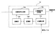
図2には、制御部14の構成ブロック図が示されている。制御部14は、具体的にはDSP等で構成され、機能ブロックとして記録信号生成部14a、LD(レーザダイオード)駆動信号生成部14b、β値算出部14c、記憶部14d及び演算部14eを有する。
【0020】
記録信号生成部14aは、記録信号をEFM変調し光ディスク100の記録速度に応じた転送レートでシリアル記録信号を出力する。なお、シリアル記録信号は、所定の記録ストラテジに応じて補正した上で出力することが好適である。記録ストラテジには大別して記録パルスのレベルを制御する方法と、記録パルス長を制御する方法があり、それぞれ記録パルスの初期においてパルス(ブーストパルス)を付加することで記録レーザパワーを増大させる方法、及び記録すべきピット長nTに対して(n−θ)T+ΔT(但し、n=3〜11、θは定数)と記録パルス長を調整する方法である。このように記録パルスのレベルやパルス長を制御することで、ピット長を所望の長さに形成でき、記録信号のジッタ等を向上させることができる。ブーストパルスは一般に記録パルスのレベル(記録パワー)に対して一定の比率のレベルで印加される。
【0021】
そして、OPC時には、記憶部14dに予めテーブル形式で記憶されている15段階の記録パワーのパルスを出力し、LD駆動信号生成部14bを介して光ピックアップ部12のLDを駆動する。
【0022】
β値算出部14cは、OPC時時において15段階の記録パワーでそれぞれ記憶されたテストデータのRF信号エンベロープからβ=(A+B)/(A−B)により算出する。但し、Aはピーク電圧、Bはボトム電圧である。算出されたβ値は順次記憶部14dに供給される。
【0023】
記憶部14dは、デフォルトの基準β値(例えば0.04)を記憶するとともに、β値算出部14cで算出されたβ値をそのときの記録パワーに対応付けて順次記憶する。
【0024】
演算部14eは、記憶部14dに記憶された各記録パワー毎のβ値に基づいて最適記録パワーを選択する。具体的には、β値の変化率を算出し、その変化率の大小に基づいて光ディスク100の基準β値を算出する。すなわち、記憶部14dには上述したようにデフォルトのβ値が記憶されているが、演算部14eはこのデフォルトβ値をそのまま用いるのではなく、記録パワーに対するβ値の変化率からデフォルトのβ値が適当か否かを判定し、適当である場合のみデフォルトのβ値を基準β値とし、適当でない場合にはこのデフォルトのβ値とは独立に最適記録パワーを設定するための基準β値とする。そして、この基準β値が得られる記録パワーを最適記録パワーとして記録信号生成部14aに供給する。
【0025】
図3には、OPCにおける制御部14の処理フローチャートが示されている。まず、15段階の記録パワーで光ディスク100の所定エリア(PCA)にテストデータを記録する(S101)。このときのパワーをPw1、Pw2、・・・、Pw15とする。そして、各記録パワーで記録されたテストデータを順次再生し、そのβ値を算出する(S102)。各記録パワーに対するβ値をそれぞれβ1、β2、・・・、β15とする。
【0026】
次に、制御部14は、記憶部14dに記憶されたβ1〜β15の傾き変化率Mを算出する(S103)。ここで、傾きは、記録パワーに対するβの変化率であり、傾き変化率は、記録パワーに対するβの傾きの変化率である。傾きKは、隣接する2つのβ値の差分を記録パワーの差分で除算して得ることができ、例えば傾きK2=(β2−β1)/(Pw2−Pw1)で算出される。傾き変化率Mは、隣接する2つの傾きの除算で得ることができ、例えば傾き変化率M3=K3/K2で算出される。
【0027】
表1には、以上のようにして算出され、記憶部14dに記憶される変化率K及び傾き変化率が示されている。
【0028】
【表1】

【0029】
したがって、制御部14は、この傾きの変化率Mの大小から、熱波形歪みを生じていないβ値の範囲を判断できる(S104)。具体的には、傾きの変化率が1より小さい所定のしきい値Mth以下であるか否かを判定し、M>Mthである場合には熱波形歪みを生じていないと判定できる。一例として、図4に示されるように、M9=K9/K8がほぼ1に等しく、M10=K10/K9が1より小さいMth以下となった場合には、β1〜β8の範囲が熱波形歪みを生じていない範囲と判定できる。
【0030】
熱波形歪みを生じていないβ値の範囲を判定した後、制御部14は次に記憶部14dに記憶されているデフォルトのβ値が熱波形歪みを生じない範囲内にあるか否かを判定する(S105)。そして、デフォルトβ値がこの範囲内にある場合には、デフォルトのβ値をそのまま用いても問題ないと判定し、制御部14はこのデフォルトのβ値を基準β値(最適β値)に設定する(S106)。
【0031】
一方、デフォルトのβ値が当該範囲内にない場合、例えば当該範囲がβ1〜β8であり、デフォルトのβ値がβ8よりも大である場合には、このデフォルトのβ値をそのまま用いると熱波形歪みを生じてしまうため、制御部14は傾き変化率Mが所定のしきい値Mth以下となるβ値の1段階低いβ値を基準β値(最適β値)に設定する(S107)。図4の場合、傾き変化率Mがしきい値Mth以下となるβ値はβ9であり、これより1段階低いβ8を基準β値に設定する。
【0032】
以上のようにして基準β値を設定した後、制御部14は基準β値が得られる記録パワーを15段から選択し、最適記録パワーに設定する(S108)。図4の例ではβ8が得られるPw8が最適記録パワーとなる。そして、設定された最適記録パワーでデータを記録する(S109)。
【0033】
このように、本実施形態では、β値の傾きの変化率の大きさから熱波形歪みを生じない範囲を抽出し、この範囲内で基準β値を設定するので、任意の光ディスク100に対して熱波形歪みを生じることなくデータを記録することができる。
【0034】
なお、本実施形態において、デフォルトのβ値は記憶部14dに記憶されているが、このデフォルトのβ値は予め固定値(例えば0.04)を記憶しておけばよい。もちろん、デフォルトのβ値がない場合には、S105の処理ではデフォルトのβ値として0を用いて処理することもできる。
【0035】
また、本実施形態では、デフォルトのβ値がβ値の変化率から抽出された熱波形歪みを生じない範囲内にあるか否かにより適当か否かを判定し、適当でない場合に熱波形歪みを生じない範囲内から基準β値を設定しているが、デフォルトのβ値とは無関係に、熱波形歪みを生じない範囲内から基準β値を設定することもできる。具体的には、S104で熱波形歪みを生じないβ値の範囲を抽出した後、直ちにS107の処理に移行すればよい。
【0036】
また、本実施形態では、傾きの変化率Mを用いて熱波形歪みを生じない範囲を抽出し基準β値を設定しているが、傾きK、すなわちβ値の変化率から基準β値を設定することもできる。具体的には、傾きKを所定値と比較し、所定値以下となったβ値より1段階低いβ値を基準値とすればよい。図4に即して説明すると、K9>K10であり、K10が所定値以下である場合にはそのときのβ(β9)よりも1段低いβ8を基準値とする如くである。
【0037】
また、本実施形態において、デフォルトのβ値が熱波形歪みを生じない範囲にある場合でも、デフォルトのβ値と当該範囲の上限β値との間のβ値(例えば中点のβ値)を基準β値に設定することも可能である。
【0038】
また、本実施形態において、光ディスク100のディスクIDに予め最適のβ値が記録されている場合には、このβ値を読み取ってデフォルトのβ値として記憶部14dに記憶し、図3の処理を行うこともできる。この場合、通常はこのデフォルトのβ値がS106で基準β値に設定されると考えられるが、光ディスク100の経年劣化などによりデフォルトのβ値が最適値からずれた場合には、S107でデフォルト値と異なるβ値が基準βに設定されることになる。
【0039】
さらに、光ディスク100のランドとグルーブにともにデータを記録する場合、ランドとグルーブでは最適記録パワーが異なるため、ランドとグルーブそれぞれに対して図3に示される処理を行い基準β値を設定することが好適である。
【0040】
また、本実施形態ではCD−Rを例にとり説明したが、CD−RW等の場合には変調度でOPCを実行している。すなわち、記録パワーと変調度の関係から変調度が飽和し始めた辺りの記録パワーを最適パワーとしているが、飽和し始めた点を直接算出するのは困難であるため、変調度の変化率γを用いてγがある値となった記録パワーに係数を乗じて最適記録パワーを算出している。したがって、CD−RW等の場合には、変調度の変化率であるγあるいはγの変化率の大小に基づいて基準変調度を設定し、この基準変調度に基づいて最適記録パワーを設定すればよい。
【0041】
【発明の効果】
以上説明したように、本発明によれば、任意の光ディスクに対して最適な記録パワーでデータを記録することができる。
【図面の簡単な説明】
【図1】 実施形態の光ディスク装置の要部構成ブロック図である。
【図2】 図1における制御部の構成ブロック図である。
【図3】 実施形態の処理フローチャートである。
【図4】 β値の傾きの変化を示すグラフ図である。
【図5】 記録パワーとβ値との関係を示すグラフ図である。
【符号の説明】
10 スピンドルモータ、12 光ピックアップ部、14 制御部、16 信号処理部、100 光ディスク。[0001]
BACKGROUND OF THE INVENTION
The present invention relates to an optical disc apparatus, and more particularly to optimization of recording power.
[0002]
[Prior art]
2. Description of the Related Art Conventionally, recording power optimization processing called OPC (Optimum Power Control) has been executed in a recordable optical disc apparatus such as a CD-R. In this OPC, the recording power is changed in a plurality of stages in a plurality of frames, for example, in 15 stages in 15 frames, test data is recorded in a predetermined test area, each test data is reproduced, and its signal quality is evaluated. The β value is usually used as the quality of the reproduction signal. The β value is a parameter calculated by β = (A + B) / (A−B) from the peak voltage (A) and bottom voltage (B) of the envelope of the reproduction RF signal, and this value is a predetermined range (for example, 0). 0.04-0.05). Then, the recording power at which a desired β value (reference β value) is obtained is selected as the optimum recording power, and thereafter data is recorded with this optimum recording power.
[0003]
JP-A-7-85494 discloses a recording power for obtaining a β value lower than a desired β value and a β value higher than the desired β value, and obtaining a desired β value by calculating these two β values. It is described that the virtual power stage is obtained and the power stage closest to the virtual stage is set as the optimum recording power.
[0004]
[Problems to be solved by the invention]
However, since there are various optical disks used for recording, there can be various β values serving as a reference. Although it is possible to select the optimum recording power using a default β value (for example, β = 0.04) prepared in advance, it is a matter of course that the optimum recording quality is not always obtained. Since the recording power is set on the basis of a β value higher than the original optimum β value, there is a possibility that the RF signal may be distorted due to thermal waveform distortion and cannot be reproduced.
[0005]
Note that a unique disk ID is recorded in advance on the optical disk, and it is possible to previously calculate and store the reference β value for each disk ID in a table on the optical disk apparatus side, but the processing becomes complicated. In addition, it is not possible to insert an optical disc that does not store the reference β value.
[0006]
The present invention has been made in view of the above-described problems of the prior art, and an object thereof is to provide an apparatus capable of recording data with high quality by setting an optimum recording power for each optical disc.
[0007]
[Means for Solving the Problems]
In order to achieve the above object, the present invention records test data on an optical disc by changing the recording power, and uses the recording power at which the β value of the reproduction signal of the test data becomes the reference β value as the optimum recording power. An optical disc apparatus for recording, wherein means for storing a default β value, means for storing a β value at each recording power when the recording power is changed, and a rate of change of the β value for each recording power It is determined whether or not the default β value is included in a range that is equal to or greater than a predetermined threshold value. If the default β value is included in the range, the default β value is determined as the reference β value. And control means for setting a new reference β value so as to be included in the range when the default β value is not included in the range .
[0008]
The present invention also relates to an optical disc apparatus that records test data on an optical disc by changing the recording power, and records the data with the recording power at which the β value of the reproduction signal of the test data becomes the reference β value as the optimum recording power. Means for storing a default β value, means for storing a β value at each recording power when the recording power is changed, and a slope change rate of the β value for each recording power is a predetermined threshold value. It is determined whether or not the default β value is included in the range as described above, and when the default β value is included in the range, the default β value is set as the reference β value, And control means for setting a new reference β value so as to be included in the range when the default β value is not included in the range .
[0009]
The present invention also relates to an optical disc apparatus that records test data on an optical disc by changing the recording power, and records the data with the recording power at which the β value of the reproduction signal of the test data becomes the reference β value as the optimum recording power. Means for storing a default β value, means for storing a β value at each recording power when the recording power is changed, and a rate of change of the β value for each recording power is a predetermined threshold value or more. And a control means for setting a new reference β value between the upper limit β value and the default β value based on the upper limit β value and the default β value. It is characterized by having .
[0010]
The present invention also relates to an optical disc apparatus that records test data on an optical disc by changing the recording power, and records the data with the recording power at which the β value of the reproduction signal of the test data becomes the reference β value as the optimum recording power. Means for storing a default β value, means for storing a β value at each recording power when the recording power is changed, and a slope change rate of the β value for each recording power is a predetermined threshold value. Control for calculating an upper limit β value in the above range and setting a new reference β value between the upper limit β value and the default β value based on the upper limit β value and the default β value Means .
[0011]
As described above, in the optical disc apparatus according to the present invention, the reference value is set from the change itself in the reproduction signal quality data such as the β value. FIG. 5 shows how the β value changes when the recording power is changed. In general, when the recording power is increased, the β value increases linearly at an almost constant rate of change, but when the recording power exceeds a certain value, thermal waveform distortion occurs, and the β value changes non-linearly at a small rate of change. I will do it. This is thought to be because the shape of the pits is distorted by excessive heat and the heat diffuses. Therefore, on the contrary, if the inclination of β value (that is, the rate of change) is constant, thermal distortion does not occur. If the inclination of β value decreases and becomes non-linear, thermal distortion occurs and the recording power is It can be determined that it is inappropriate. Therefore, by selecting a value that does not cause thermal distortion from a change in β value or the like and using it as a reference value, an optimum reference value that matches the optical disc can be set, and this is used to optimize recording power. be able to.
[0012]
In the present invention, it is not necessary to detect the optimum reference value of the optical disc in advance and record it on the disc ID or the like, and the optimum recording power can be set for each optical disc.
[0013]
DETAILED DESCRIPTION OF THE INVENTION
Hereinafter, embodiments of the present invention will be described with reference to the drawings.
[0014]
FIG. 1 shows a configuration diagram of a main part of an optical disc apparatus according to the present embodiment. The optical disc apparatus includes an
[0015]
The
[0016]
The
[0017]
The
[0018]
When the optimum recording power is selected and data is recorded, the
[0019]
FIG. 2 shows a configuration block diagram of the
[0020]
The recording
[0021]
During OPC, the
[0022]
The β
[0023]
The
[0024]
The computing unit 14e selects the optimum recording power based on the β value for each recording power stored in the
[0025]
FIG. 3 shows a process flowchart of the
[0026]
Next, the
[0027]
Table 1 shows the change rate K and the inclination change rate calculated as described above and stored in the
[0028]
[Table 1]
[0029]
Therefore, the
[0030]
After determining the range of β values that do not cause thermal waveform distortion, the
[0031]
On the other hand, when the default β value is not within the range, for example, when the range is β1 to β8, and the default β value is larger than β8, if this default β value is used as it is, a thermal waveform is used. Since distortion occurs, the
[0032]
After setting the reference β value as described above, the
[0033]
As described above, in this embodiment, a range in which thermal waveform distortion does not occur is extracted from the magnitude of the change rate of the slope of the β value, and the reference β value is set within this range. Data can be recorded without causing thermal waveform distortion.
[0034]
In the present embodiment, the default β value is stored in the
[0035]
Further, in the present embodiment, whether or not the default β value is appropriate is determined by whether or not the default β value is within a range in which the thermal waveform distortion extracted from the change rate of the β value does not occur. The reference β value is set from within a range that does not cause the occurrence of the error. However, regardless of the default β value, the reference β value can also be set from within the range that does not cause the thermal waveform distortion. Specifically, after extracting a range of β values that do not cause thermal waveform distortion in S104, the process may immediately proceed to S107.
[0036]
In this embodiment, a range in which thermal waveform distortion does not occur is extracted by using the slope change rate M and the reference β value is set. However, the reference β value is set from the slope K, that is, the β value change rate. You can also Specifically, the slope K is compared with a predetermined value, and a β value that is one step lower than the β value that is equal to or less than the predetermined value may be used as the reference value. Referring to FIG. 4, K9> K10, and when K10 is equal to or less than a predetermined value, β8 that is one step lower than β (β9) at that time is set as the reference value.
[0037]
Further, in the present embodiment, even when the default β value is in a range in which thermal waveform distortion does not occur, a β value between the default β value and the upper limit β value of the range (for example, the β value at the midpoint) It is also possible to set the reference β value.
[0038]
In the present embodiment, when an optimal β value is recorded in advance in the disc ID of the
[0039]
Further, when data is recorded on both the land and the groove of the
[0040]
In this embodiment, the CD-R has been described as an example. However, in the case of a CD-RW or the like, OPC is executed with a modulation degree. That is, the optimum recording power is the power at which the modulation degree starts to saturate due to the relationship between the recording power and the modulation degree, but it is difficult to directly calculate the point at which the modulation degree has started to be saturated. Is used to calculate the optimum recording power by multiplying the recording power with a certain value by γ. Therefore, in the case of CD-RW or the like, if the reference modulation degree is set based on the change rate of γ or the change rate of γ, and the optimum recording power is set based on the reference modulation degree. Good.
[0041]
【The invention's effect】
As described above, according to the present invention, data can be recorded on an arbitrary optical disc with an optimum recording power.
[Brief description of the drawings]
FIG. 1 is a block diagram illustrating a main part of an optical disc apparatus according to an embodiment.
FIG. 2 is a block diagram showing the configuration of a control unit in FIG. 1;
FIG. 3 is a process flowchart of the embodiment.
FIG. 4 is a graph showing changes in the slope of the β value.
FIG. 5 is a graph showing the relationship between recording power and β value.
[Explanation of symbols]
10 spindle motor, 12 optical pickup unit, 14 control unit, 16 signal processing unit, 100 optical disc.
Claims (6)
デフォルトのβ値を記憶する手段と、
前記記録パワーを変化させたときの各記録パワーにおけるβ値を記憶する手段と、
前記記録パワー毎のβ値の変化率が所定のしきい値以上となる範囲に前記デフォルトのβ値が含まれるか否かを判定し、前記デフォルトのβ値が前記範囲内に含まれる場合には前記デフォルトのβ値を前記基準β値に設定し、前記デフォルトのβ値が前記範囲内に含まれない場合には前記範囲内に含まれるように新たな基準β値を設定する制御手段と、
を有することを特徴とする光ディスク装置。An optical disc apparatus for recording test data on an optical disc by changing a recording power, and recording data with a recording power at which a β value of a reproduction signal of the test data becomes a reference β value as an optimum recording power,
Means for storing a default β value;
Means for storing a β value at each recording power when the recording power is changed;
It is determined whether or not the default β value is included in a range in which the change rate of the β value for each recording power is equal to or greater than a predetermined threshold, and when the default β value is included in the range Control means for setting the default β value to the reference β value and, if the default β value is not included in the range, setting a new reference β value to be included in the range; ,
An optical disc apparatus comprising:
デフォルトのβ値を記憶する手段と、
前記記録パワーを変化させたときの各記録パワーにおけるβ値を記憶する手段と、
前記記録パワー毎のβ値の傾き変化率が所定のしきい値以上となる範囲に前記デフォルトのβ値が含まれるか否かを判定し、前記デフォルトのβ値が前記範囲内に含まれる場合には前記デフォルトのβ値を前記基準β値に設定し、前記デフォルトのβ値が前記範囲内に含まれない場合には前記範囲内に含まれるように新たな基準β値を設定する制御手段と、
を有することを特徴とする光ディスク装置。An optical disc apparatus for recording test data on an optical disc by changing a recording power, and recording data with a recording power at which a β value of a reproduction signal of the test data becomes a reference β value as an optimum recording power,
Means for storing a default β value;
Means for storing a β value at each recording power when the recording power is changed;
When determining whether or not the default β value is included in a range in which the slope change rate of the β value for each recording power is equal to or greater than a predetermined threshold, and the default β value is included in the range Control means for setting the default β value to the reference β value and, if the default β value is not included in the range, setting a new reference β value to be included in the range When,
An optical disc apparatus comprising:
前記デフォルトのβ値は、固定値であることを特徴とする光ディスク装置。The apparatus according to claim 1,
The optical disc apparatus according to claim 1, wherein the default β value is a fixed value.
前記デフォルトのβ値は、データを記録すべき光ディスク毎に設定され前記光ディスクから読み出されて記憶されることを特徴とする光ディスク装置。The apparatus according to claim 1,
The default β value is set for each optical disk on which data is to be recorded, and is read from the optical disk and stored therein.
デフォルトのβ値を記憶する手段と、
前記記録パワーを変化させたときの各記録パワーにおけるβ値を記憶する手段と、
前記記録パワー毎のβ値の変化率が所定のしきい値以上となる範囲の上限β値を算出し、前記上限β値と前記デフォルトのβ値とに基づいて前記上限β値と前記デフォルトのβ値との間にある新たな基準β値を設定する制御手段と、
を有することを特徴とする光ディスク装置。An optical disc apparatus for recording test data on an optical disc by changing a recording power, and recording data with a recording power at which a β value of a reproduction signal of the test data becomes a reference β value as an optimum recording power,
Means for storing a default β value;
Means for storing a β value at each recording power when the recording power is changed;
An upper limit β value in a range in which a change rate of the β value for each recording power is a predetermined threshold or more is calculated, and the upper limit β value and the default β value are calculated based on the upper limit β value and the default β value. control means for setting a new reference β value between the β value;
An optical disc apparatus comprising:
デフォルトのβ値を記憶する手段と、
前記記録パワーを変化させたときの各記録パワーにおけるβ値を記憶する手段と、
前記記録パワー毎のβ値の傾き変化率が所定のしきい値以上となる範囲の上限β値を算出し、前記上限β値と前記デフォルトのβ値とに基づいて前記上限β値と前記デフォルトのβ値との間にある新たな基準β値を設定する制御手段と、
を有することを特徴とする光ディスク装置。An optical disc apparatus for recording test data on an optical disc by changing a recording power, and recording data with a recording power at which a β value of a reproduction signal of the test data becomes a reference β value as an optimum recording power,
Means for storing a default β value;
Means for storing a β value at each recording power when the recording power is changed;
An upper limit β value in a range in which a slope change rate of the β value for each recording power is a predetermined threshold or more is calculated, and the upper limit β value and the default β value are calculated based on the upper limit β value and the default β value. Control means for setting a new reference β value between the β value of
An optical disc apparatus comprising:
Priority Applications (5)
| Application Number | Priority Date | Filing Date | Title |
|---|---|---|---|
| JP2001190670A JP3722017B2 (en) | 2001-06-25 | 2001-06-25 | Optical disk device |
| TW091106476A TWI284316B (en) | 2001-06-25 | 2002-04-01 | Disk device |
| CNB021180342A CN1260711C (en) | 2001-06-25 | 2002-04-18 | CD apparatus |
| KR10-2002-0021492A KR100489543B1 (en) | 2001-06-25 | 2002-04-19 | Optical disk device |
| US10/180,816 US6885617B2 (en) | 2001-06-25 | 2002-06-25 | Optical disk apparatus |
Applications Claiming Priority (1)
| Application Number | Priority Date | Filing Date | Title |
|---|---|---|---|
| JP2001190670A JP3722017B2 (en) | 2001-06-25 | 2001-06-25 | Optical disk device |
Related Child Applications (1)
| Application Number | Title | Priority Date | Filing Date |
|---|---|---|---|
| JP2005215059A Division JP3778212B2 (en) | 2005-07-25 | 2005-07-25 | Optical disk device |
Publications (2)
| Publication Number | Publication Date |
|---|---|
| JP2003006868A JP2003006868A (en) | 2003-01-10 |
| JP3722017B2 true JP3722017B2 (en) | 2005-11-30 |
Family
ID=19029407
Family Applications (1)
| Application Number | Title | Priority Date | Filing Date |
|---|---|---|---|
| JP2001190670A Expired - Fee Related JP3722017B2 (en) | 2001-06-25 | 2001-06-25 | Optical disk device |
Country Status (5)
| Country | Link |
|---|---|
| US (1) | US6885617B2 (en) |
| JP (1) | JP3722017B2 (en) |
| KR (1) | KR100489543B1 (en) |
| CN (1) | CN1260711C (en) |
| TW (1) | TWI284316B (en) |
Families Citing this family (18)
| Publication number | Priority date | Publication date | Assignee | Title |
|---|---|---|---|---|
| KR100505640B1 (en) * | 2002-09-09 | 2005-08-03 | 삼성전자주식회사 | Optimum write power decision apparatus and method in the disc drive |
| JP3924780B2 (en) * | 2002-09-20 | 2007-06-06 | 日本電気株式会社 | Laser power selection method, information recording medium, and information recording apparatus |
| KR100538848B1 (en) | 2003-03-04 | 2005-12-23 | 주식회사 히타치엘지 데이터 스토리지 코리아 | Method for controlling the optimal writing power of optical disc |
| CN1317697C (en) * | 2003-03-25 | 2007-05-23 | 株式会社理光 | Optical information recording device, optical information recording medium, optical information recording method, program, and computer-readable information storage medium |
| KR100545807B1 (en) * | 2003-11-04 | 2006-01-24 | 엘지전자 주식회사 | Optimal Recording Power Search Method in Recording Device and Recording Medium Therefor |
| TW200523902A (en) | 2004-01-05 | 2005-07-16 | Taiyo Yuden Kk | Optical data recording method, recording apparatus and signal processing circuit |
| JP2005322304A (en) * | 2004-05-07 | 2005-11-17 | Taiyo Yuden Co Ltd | Optical information recording device |
| TWI356407B (en) * | 2005-01-11 | 2012-01-11 | Via Tech Inc | Monitor and adjust method for optical disc recordi |
| KR100684410B1 (en) * | 2005-01-21 | 2007-02-16 | 엘지전자 주식회사 | Method for controlling writing power in optical disc driver |
| KR100611246B1 (en) * | 2005-02-07 | 2006-08-10 | 삼성전자주식회사 | Read and write apparatus and method for disc |
| US20060256679A1 (en) * | 2005-05-10 | 2006-11-16 | Kuang-Jung Chang | Laser power controlling method for recording data and related apparatus |
| KR100657336B1 (en) * | 2005-07-13 | 2006-12-14 | 삼성전자주식회사 | Method for determining optimum recording power of optical recording medium and recording/reproducing apparatus using the same |
| JP4083761B2 (en) * | 2005-07-22 | 2008-04-30 | 東芝サムスン ストレージ・テクノロジー株式会社 | Recording power value determination method and optical disc apparatus |
| KR100801474B1 (en) * | 2006-06-13 | 2008-02-12 | 엘지전자 주식회사 | Method for recording data in optical disc device |
| JP2008027501A (en) * | 2006-07-20 | 2008-02-07 | Sanyo Electric Co Ltd | Optical disk and optical disk unit |
| JP4864935B2 (en) * | 2008-05-16 | 2012-02-01 | 株式会社東芝 | Information recording method, information recording apparatus, and information storage medium |
| JP5553655B2 (en) * | 2010-03-26 | 2014-07-16 | 株式会社日立エルジーデータストレージ | Optical disk recording quality evaluation method and optical disk storage device |
| CN106237840B (en) * | 2016-08-25 | 2018-10-30 | 北京航天环境工程有限公司 | VOC exhaust treatment systems |
Family Cites Families (18)
| Publication number | Priority date | Publication date | Assignee | Title |
|---|---|---|---|---|
| JP3124720B2 (en) | 1995-04-14 | 2001-01-15 | 株式会社リコー | Information recording / reproducing method, information recording / reproducing device, and information recording medium |
| JPH0785494A (en) | 1993-09-17 | 1995-03-31 | Pioneer Electron Corp | Information recorder/reproducer |
| JP2827855B2 (en) * | 1993-11-12 | 1998-11-25 | ヤマハ株式会社 | Optical disk recording device |
| JPH07235055A (en) * | 1994-02-23 | 1995-09-05 | Taiyo Yuden Co Ltd | Method for setting recording laser beam for optical disk and optical disk recording/reproducing device |
| KR200235354Y1 (en) * | 1995-12-20 | 2001-10-25 | 구자홍 | Optimal laser recording power detection device |
| JPH1040548A (en) * | 1996-07-26 | 1998-02-13 | Taiyo Yuden Co Ltd | Running opc method for optical disk and optical disk recording/reproducing apparatus |
| JP3259642B2 (en) * | 1996-08-14 | 2002-02-25 | ヤマハ株式会社 | Optical disk recording method |
| US6285647B1 (en) * | 1997-04-10 | 2001-09-04 | U.S. Philis Corporation | Method and device for writing an optical record carrier |
| US6392970B1 (en) * | 1997-08-04 | 2002-05-21 | Sharp Kabushiki Kaisha | Reproducing light quantity control method for optical memory device, and reproducing light quantity control device, and optical recording medium |
| KR100288783B1 (en) * | 1998-09-18 | 2001-05-02 | 구자홍 | Detecting and storing recording optical power of optical recording medium, apparatus and method for controlling recording optical power using same |
| KR20000042985A (en) * | 1998-12-28 | 2000-07-15 | 윤종용 | Method for storing recording power of optical disc |
| KR20010003547A (en) * | 1999-06-24 | 2001-01-15 | 윤종용 | Method for detecting of optimum writing power in a optic disk |
| JP3697962B2 (en) * | 1999-08-20 | 2005-09-21 | ティアック株式会社 | Optical disk drive device |
| KR100314069B1 (en) * | 1999-10-22 | 2001-11-17 | 구자홍 | Optimal writing apparatus and method using normalizing method of optical recording medium |
| KR20010058863A (en) * | 1999-12-30 | 2001-07-06 | 구자홍 | Write power control method for optical recording and reproducting appratus |
| CN1252687C (en) | 2001-02-05 | 2006-04-19 | 雅马哈株式会社 | Optical disc device for regulating recording speed and laser power |
| JP3736369B2 (en) | 2001-03-02 | 2006-01-18 | ヤマハ株式会社 | Optical disc recording laser power determination method and optical disc recording apparatus |
| JP3858613B2 (en) * | 2001-03-23 | 2006-12-20 | ティアック株式会社 | Optical disk device |
-
2001
- 2001-06-25 JP JP2001190670A patent/JP3722017B2/en not_active Expired - Fee Related
-
2002
- 2002-04-01 TW TW091106476A patent/TWI284316B/en not_active IP Right Cessation
- 2002-04-18 CN CNB021180342A patent/CN1260711C/en not_active Expired - Fee Related
- 2002-04-19 KR KR10-2002-0021492A patent/KR100489543B1/en not_active IP Right Cessation
- 2002-06-25 US US10/180,816 patent/US6885617B2/en not_active Expired - Fee Related
Also Published As
| Publication number | Publication date |
|---|---|
| US6885617B2 (en) | 2005-04-26 |
| KR100489543B1 (en) | 2005-05-16 |
| KR20030001235A (en) | 2003-01-06 |
| TWI284316B (en) | 2007-07-21 |
| CN1260711C (en) | 2006-06-21 |
| US20030007435A1 (en) | 2003-01-09 |
| JP2003006868A (en) | 2003-01-10 |
| CN1393858A (en) | 2003-01-29 |
Similar Documents
| Publication | Publication Date | Title |
|---|---|---|
| JP3722017B2 (en) | Optical disk device | |
| US6504806B1 (en) | Optical disk recording apparatus | |
| US6958962B2 (en) | Optical disk device | |
| JP2005004906A (en) | Method and device for recording information | |
| JP2006277949A (en) | Apparatus for recording data on optical recording medium | |
| EP1453041B1 (en) | Optical disk recording method and apparatus using alternative strategies of laser beam control | |
| JP3778212B2 (en) | Optical disk device | |
| JP2003208716A (en) | Optical disk apparatus | |
| US8085634B2 (en) | Optical disk drive, and method for determining recording strategy | |
| JP2003228840A (en) | Information recording apparatus | |
| JP4564960B2 (en) | Information recording apparatus, information recording method, and information recording program | |
| JP3876676B2 (en) | Optical disk device | |
| TWI284894B (en) | Information recording method and information recording apparatus | |
| EP1946312B1 (en) | Method of adjusting writing parameters, optical disc writer and method of recording data using the same | |
| JP3772710B2 (en) | Optical disk device | |
| EP1191520A2 (en) | Information record apparatus, information record method, and information record medium | |
| JP3753104B2 (en) | Optical disk device | |
| JP3772709B2 (en) | Optical disk device | |
| JP3693849B2 (en) | Optical information recording / reproducing apparatus | |
| JP4326900B2 (en) | Light modulation recording condition setting device, light modulation recording condition setting method, light modulation recording / reproducing device, control program, and recording medium | |
| JP4049147B2 (en) | Optical disk device | |
| JP2003006867A (en) | Optical disk device | |
| JP2003233907A (en) | Optical disk device | |
| JP2003303416A (en) | Optical disk unit | |
| KR20060027906A (en) | Optical disk recording/reproducing apparatus and method for determining write strategy thereof |
Legal Events
| Date | Code | Title | Description |
|---|---|---|---|
| A977 | Report on retrieval |
Free format text: JAPANESE INTERMEDIATE CODE: A971007 Effective date: 20040617 |
|
| A131 | Notification of reasons for refusal |
Free format text: JAPANESE INTERMEDIATE CODE: A131 Effective date: 20040629 |
|
| A521 | Request for written amendment filed |
Free format text: JAPANESE INTERMEDIATE CODE: A523 Effective date: 20040827 |
|
| RD04 | Notification of resignation of power of attorney |
Free format text: JAPANESE INTERMEDIATE CODE: A7424 Effective date: 20040827 |
|
| A131 | Notification of reasons for refusal |
Free format text: JAPANESE INTERMEDIATE CODE: A131 Effective date: 20050524 |
|
| A521 | Request for written amendment filed |
Free format text: JAPANESE INTERMEDIATE CODE: A523 Effective date: 20050725 |
|
| TRDD | Decision of grant or rejection written | ||
| A01 | Written decision to grant a patent or to grant a registration (utility model) |
Free format text: JAPANESE INTERMEDIATE CODE: A01 Effective date: 20050823 |
|
| A61 | First payment of annual fees (during grant procedure) |
Free format text: JAPANESE INTERMEDIATE CODE: A61 Effective date: 20050905 |
|
| R150 | Certificate of patent or registration of utility model |
Free format text: JAPANESE INTERMEDIATE CODE: R150 |
|
| FPAY | Renewal fee payment (event date is renewal date of database) |
Free format text: PAYMENT UNTIL: 20080922 Year of fee payment: 3 |
|
| S531 | Written request for registration of change of domicile |
Free format text: JAPANESE INTERMEDIATE CODE: R313531 |
|
| FPAY | Renewal fee payment (event date is renewal date of database) |
Free format text: PAYMENT UNTIL: 20080922 Year of fee payment: 3 |
|
| R350 | Written notification of registration of transfer |
Free format text: JAPANESE INTERMEDIATE CODE: R350 |
|
| FPAY | Renewal fee payment (event date is renewal date of database) |
Free format text: PAYMENT UNTIL: 20080922 Year of fee payment: 3 |
|
| FPAY | Renewal fee payment (event date is renewal date of database) |
Free format text: PAYMENT UNTIL: 20090922 Year of fee payment: 4 |
|
| FPAY | Renewal fee payment (event date is renewal date of database) |
Free format text: PAYMENT UNTIL: 20100922 Year of fee payment: 5 |
|
| FPAY | Renewal fee payment (event date is renewal date of database) |
Free format text: PAYMENT UNTIL: 20100922 Year of fee payment: 5 |
|
| FPAY | Renewal fee payment (event date is renewal date of database) |
Free format text: PAYMENT UNTIL: 20110922 Year of fee payment: 6 |
|
| FPAY | Renewal fee payment (event date is renewal date of database) |
Free format text: PAYMENT UNTIL: 20120922 Year of fee payment: 7 |
|
| FPAY | Renewal fee payment (event date is renewal date of database) |
Free format text: PAYMENT UNTIL: 20130922 Year of fee payment: 8 |
|
| LAPS | Cancellation because of no payment of annual fees |