JP3720147B2 - A method for logical network design in multi-service networks. - Google Patents
A method for logical network design in multi-service networks. Download PDFInfo
- Publication number
- JP3720147B2 JP3720147B2 JP29428196A JP29428196A JP3720147B2 JP 3720147 B2 JP3720147 B2 JP 3720147B2 JP 29428196 A JP29428196 A JP 29428196A JP 29428196 A JP29428196 A JP 29428196A JP 3720147 B2 JP3720147 B2 JP 3720147B2
- Authority
- JP
- Japan
- Prior art keywords
- network
- determining
- link
- sensitivity
- network performance
- Prior art date
- Legal status (The legal status is an assumption and is not a legal conclusion. Google has not performed a legal analysis and makes no representation as to the accuracy of the status listed.)
- Expired - Fee Related
Links
Images


Classifications
-
- H—ELECTRICITY
- H04—ELECTRIC COMMUNICATION TECHNIQUE
- H04Q—SELECTING
- H04Q11/00—Selecting arrangements for multiplex systems
- H04Q11/04—Selecting arrangements for multiplex systems for time-division multiplexing
- H04Q11/0428—Integrated services digital network, i.e. systems for transmission of different types of digitised signals, e.g. speech, data, telecentral, television signals
- H04Q11/0478—Provisions for broadband connections
-
- H—ELECTRICITY
- H04—ELECTRIC COMMUNICATION TECHNIQUE
- H04L—TRANSMISSION OF DIGITAL INFORMATION, e.g. TELEGRAPHIC COMMUNICATION
- H04L49/00—Packet switching elements
- H04L49/20—Support for services
- H04L49/205—Quality of Service based
-
- H—ELECTRICITY
- H04—ELECTRIC COMMUNICATION TECHNIQUE
- H04L—TRANSMISSION OF DIGITAL INFORMATION, e.g. TELEGRAPHIC COMMUNICATION
- H04L49/00—Packet switching elements
- H04L49/25—Routing or path finding in a switch fabric
-
- H—ELECTRICITY
- H04—ELECTRIC COMMUNICATION TECHNIQUE
- H04Q—SELECTING
- H04Q3/00—Selecting arrangements
- H04Q3/0016—Arrangements providing connection between exchanges
-
- H—ELECTRICITY
- H04—ELECTRIC COMMUNICATION TECHNIQUE
- H04L—TRANSMISSION OF DIGITAL INFORMATION, e.g. TELEGRAPHIC COMMUNICATION
- H04L12/00—Data switching networks
- H04L12/54—Store-and-forward switching systems
- H04L12/56—Packet switching systems
- H04L12/5601—Transfer mode dependent, e.g. ATM
- H04L2012/5619—Network Node Interface, e.g. tandem connections, transit switching
- H04L2012/562—Routing
-
- H—ELECTRICITY
- H04—ELECTRIC COMMUNICATION TECHNIQUE
- H04L—TRANSMISSION OF DIGITAL INFORMATION, e.g. TELEGRAPHIC COMMUNICATION
- H04L12/00—Data switching networks
- H04L12/54—Store-and-forward switching systems
- H04L12/56—Packet switching systems
- H04L12/5601—Transfer mode dependent, e.g. ATM
- H04L2012/5619—Network Node Interface, e.g. tandem connections, transit switching
- H04L2012/5623—Network design, dimensioning, topology or optimisation
-
- H—ELECTRICITY
- H04—ELECTRIC COMMUNICATION TECHNIQUE
- H04L—TRANSMISSION OF DIGITAL INFORMATION, e.g. TELEGRAPHIC COMMUNICATION
- H04L12/00—Data switching networks
- H04L12/54—Store-and-forward switching systems
- H04L12/56—Packet switching systems
- H04L12/5601—Transfer mode dependent, e.g. ATM
- H04L2012/5625—Operations, administration and maintenance [OAM]
- H04L2012/5626—Network management, e.g. Intelligent nets
-
- H—ELECTRICITY
- H04—ELECTRIC COMMUNICATION TECHNIQUE
- H04L—TRANSMISSION OF DIGITAL INFORMATION, e.g. TELEGRAPHIC COMMUNICATION
- H04L12/00—Data switching networks
- H04L12/54—Store-and-forward switching systems
- H04L12/56—Packet switching systems
- H04L12/5601—Transfer mode dependent, e.g. ATM
- H04L2012/5629—Admission control
- H04L2012/5631—Resource management and allocation
- H04L2012/5632—Bandwidth allocation
-
- H—ELECTRICITY
- H04—ELECTRIC COMMUNICATION TECHNIQUE
- H04L—TRANSMISSION OF DIGITAL INFORMATION, e.g. TELEGRAPHIC COMMUNICATION
- H04L12/00—Data switching networks
- H04L12/54—Store-and-forward switching systems
- H04L12/56—Packet switching systems
- H04L12/5601—Transfer mode dependent, e.g. ATM
- H04L2012/5678—Traffic aspects, e.g. arbitration, load balancing, smoothing, buffer management
- H04L2012/5684—Characteristics of traffic flows
-
- H—ELECTRICITY
- H04—ELECTRIC COMMUNICATION TECHNIQUE
- H04L—TRANSMISSION OF DIGITAL INFORMATION, e.g. TELEGRAPHIC COMMUNICATION
- H04L49/00—Packet switching elements
- H04L49/50—Overload detection or protection within a single switching element
-
- H—ELECTRICITY
- H04—ELECTRIC COMMUNICATION TECHNIQUE
- H04Q—SELECTING
- H04Q2213/00—Indexing scheme relating to selecting arrangements in general and for multiplex systems
- H04Q2213/1305—Software aspects
-
- H—ELECTRICITY
- H04—ELECTRIC COMMUNICATION TECHNIQUE
- H04Q—SELECTING
- H04Q2213/00—Indexing scheme relating to selecting arrangements in general and for multiplex systems
- H04Q2213/13141—Hunting for free outlet, circuit or channel
-
- H—ELECTRICITY
- H04—ELECTRIC COMMUNICATION TECHNIQUE
- H04Q—SELECTING
- H04Q2213/00—Indexing scheme relating to selecting arrangements in general and for multiplex systems
- H04Q2213/13164—Traffic (registration, measurement,...)
-
- H—ELECTRICITY
- H04—ELECTRIC COMMUNICATION TECHNIQUE
- H04Q—SELECTING
- H04Q2213/00—Indexing scheme relating to selecting arrangements in general and for multiplex systems
- H04Q2213/13166—Fault prevention
-
- H—ELECTRICITY
- H04—ELECTRIC COMMUNICATION TECHNIQUE
- H04Q—SELECTING
- H04Q2213/00—Indexing scheme relating to selecting arrangements in general and for multiplex systems
- H04Q2213/13332—Broadband, CATV, dynamic bandwidth allocation
-
- H—ELECTRICITY
- H04—ELECTRIC COMMUNICATION TECHNIQUE
- H04Q—SELECTING
- H04Q2213/00—Indexing scheme relating to selecting arrangements in general and for multiplex systems
- H04Q2213/13335—Simulation, emulation
-
- H—ELECTRICITY
- H04—ELECTRIC COMMUNICATION TECHNIQUE
- H04Q—SELECTING
- H04Q2213/00—Indexing scheme relating to selecting arrangements in general and for multiplex systems
- H04Q2213/1338—Inter-exchange connection
-
- H—ELECTRICITY
- H04—ELECTRIC COMMUNICATION TECHNIQUE
- H04Q—SELECTING
- H04Q2213/00—Indexing scheme relating to selecting arrangements in general and for multiplex systems
- H04Q2213/13399—Virtual channel/circuits
-
- H—ELECTRICITY
- H04—ELECTRIC COMMUNICATION TECHNIQUE
- H04Q—SELECTING
- H04Q2213/00—Indexing scheme relating to selecting arrangements in general and for multiplex systems
- H04Q2213/13503—Indexing scheme relating to selecting arrangements in general and for multiplex systems object-oriented systems
Description
【0001】
【発明の属する技術分野】
本発明は、マルチサービストラヒックを運ぶ通信網、より詳細には、このような通信網における論理網設計のための方法に関する。
【0002】
【従来の技術】
網は、情報(例えば、データ、音声、テキスト、ビデオ、等)を、その網に接続された通信デバイス(つまり、情報を入力および出力するためのデバイス、例えば、コンピュータ端末、マルチメディアワークステーション、ファクスマシン、プリンタ、サーバ、電話機、ビデオ電話、等)の間で交換あるいは伝送するための主要な手段である。
【0003】
網は、典型的には、互いにおよび通信デバイスに、リンクによって接続された交換ノードから構成される。各リンクは、個々の特徴ある帯域幅、つまり、リンク容量を持つ。通信デバイスから網に入力される情報は、任意の形式を持つことができるが、ただし、通常は、固定された長さのパケットあるいはセルにフォーマット化される。情報を二つの通信デバイスの間で交換したい場合、網内に、それらデバイスが関連するノード(以降、発信ノードおよび宛先ノードと呼ばれる)を接続する経路が設定される。
【0004】
多くの網においては、指定された発信元と宛先との間で、網内のセットの物理経路(つまり、発信ノードと宛先ノード、場合によっては一つあるいは複数の中間ノード、および含まれるノードを接続するリンクから構成される経路)を通じてある与えられた通信ストリームが運ばれる(“通信ストリーム(communication stream)という用語は、網に発信ノードと宛先ノードの所で接続された通信デバイス間で交換される情報を表す)。これら、各経路が所定の帯域幅を持つことを特徴とする、セットの発信から宛先までの経路は、通常、“論理(logical)”あるいは“仮想(virtual)”経路と呼ばれる。網内のある物理経路の全てあるいはある部分に沿って幾つかのこれら仮想経路が、同時に存在することもしばしばある。典型的には、最初は、ある仮想経路を構成するために、幾つかの異なる物理経路が選択されるが、いったんこの仮想経路が設定されると、こうして選択された物理経路は、一般的には、その通信ストリームに対して設定されたままにとどまる。
【0005】
また、これら複数の論理経路、およびこれら論理経路をグループ化することによって形成された一つあるいはそれ以上の論理サブ網は、結果として、二つの特徴的な網の、両方を与えることに注意する。つまり、第一の網は、その網の様々なユーザに提供するための固定され、どちらかといえば、永久的な、セットの論理サブ網を持ち、第二の網においては、その網を構成する論理サブ網のサイズが変化するトラヒック要件を扱うために時間によって変更される(re-dimensionedされる)。
【0006】
論理網設計の一つの重要な要素は、網を通じての、通信ストリームの推定されるトラヒックを運ぶための十分な容量を持つ、セットの物理経路を選択するプロセスである。このプロセスは、網トポロジ、現在利用可能な資源(例えば、ノード内のバッファ空間およびリンクの容量)、および網のユーザに対して約束されたサービス品質(例えば、保証された帯域幅あるいは最大セル損失確率)などの様々な要因を考慮する。
【0007】
非同期転送モード(Asynchronous Transfer Mode,ATM)は、上に説明の網内でしばしば適用されるネットワーキングプロトコルであり、これは、高速デジタル音声およびデータ通信を効率的にサポートするように設計されている。ATMに基づく高速通信網は、異なるトラヒック特性を持つ多数のサービスを統合する。つまり、さなざまなトラヒック特性として、定ビット速度(特性)から、高度にバースト性の可変ビット速度(特性)に至までが統合される。有効帯域幅(effective bandwidth)という考え方は、緩衝を持つ伝送の背景下で使用される可変ビット速度トラヒックから、緩衝を持たない伝送設備内での定ビット速度トラヒックへの翻訳(translation)における重要な概念である。この有効帯域幅概念については、本発明人の一人による審理中の合衆国特許出願第08/506160号,“A METHOD FOR ADMISSION CONTROL AND ROUTING BY ALLOCATING NETWORK RESOURCES IN NETWORK NODES"、において詳細に説明されている。
【0008】
このような有効帯域幅翻訳(effective bandwidth translation)という概念を使用した場合、ATM網は、少なくとも呼を扱うという目的からは、マルチレート回路交換損失網(multirate circuit-switched,loss networks)とみなすことができ、この網においては、各サービスの記述には、そのサービスを運ぶ各リンクに対する特性帯域幅要件あるいは特性速度が含まれる。表面上は、このような翻訳は、単一レート回路交換網設計(single-rate,circuit switched network design) に関する多量の従来の研究が存在する[これに関しては、例えば、A.Girard,Routing and Dimensioning in Circuit-Switched Networks,Addidon-Wesley,1990,および、G.R.Ash,R.H.Cardwell,and R.P.Murray,“Design and optimization of networks with dynamic routing",Bell Syst. Tech. J.,60(8):1787-1820,Oct.1981を参照]ために、従来の技術を使用する網分析に対しても機会を提供するように見える。しかしながら、よく調べてみると、網設計問題、特に、ATM網と関連するマルチレート、マルチサービス特性に対する仮想経路に対する容量割当ておよびルーティングに関する設計問題を、従来の技術によって扱われるそれらと実質的に別なものとし、より手に負えないものとする、様々な特性が存在することがわかる。
【0009】
【発明が解決しようとする課題】
特に注意すべき3つの特性が存在する。第一は、永久仮想回路とは対象的に、交換仮想回路は、ランダムな到着時間およびランダムな保持時間を持ち、このために、これらランダム性を考慮に入れる設計手続きが必要となる。第二の特性は、網リンクのサイズに関する。一例として、最小のサービス速度が8Kbpsの様々なサービスのトラヒックを運ぶ帯域幅150Mbpsのリンクについて考える。回路交換モデルにおいては、このようなリンクは、最も小さなサービス速度が単一の回路と等価であると考えて、18,750の回路を持つものとみなされる。高速光伝送リンクは2.5Gbpsを運ぶことができるために、ここでは、一般的にCとして表される回路内のリンク容量は、将来の網においては非常に大きくなることが見込まれる。(リンク容量Cは、帯域幅にて等価的に表現できることに注意する)。第二の(第三の)注目すべき特性は、サービスSの数が、特に、“情報スーパーハイウエイ(information superhighway)”がますます現実的となりつつあることからみて、近い将来に、10−25のレンジとなり、中期的には、さらに増加することが見込まれることである。現在のおよび予想される将来のマルチサービス、マルチレート網、例えば、ATM網が、特徴として持つこのような多数の容量およびサービスパラメータのために、従来の技術による網分析法をこれら網に適用しようとする試みは、計算機の追跡能力の点から困難であると考えられる。
【0010】
【課題を解決するための手段】
マルチレート回路交換分析に基づく網最適化のための方法について開示される。本発明の方法によると、網損失確率が、セットの固定点方程式の解として決定され、申し出負荷および損失確率の関数としての網性能の感度が、セットの線形方程式の解として決定される。固定点方程式および感度方程式の両方とも、これを解くための計算上の複雑さが、完全解を計算するには不可能なほどのオーダとなるために、網損失確率および網感度の両方に対して、これらの解を与えるために、漸近近似が適用される。次に、グローバル最適化手続きが、反復最急上昇手続きを使用して適用され、セットの仮想経路ルーティングおよび容量割当てが得られる。
【0011】
本発明のもう一つの実施例として、漸近計算と非漸近(完全)計算とを協力的に使用することを可能にする統合ハイブリッドアプローチが提供される。本発明のさらにもう一つの実施例として、トラヒック状態が変動する状況において本発明の網最適化手続きを遂行するための方法論が提供される。
さらに、本発明の最適化方法論を、静的および動的両トラヒック状況に対して自動的に遂行するための本発明のソフトウエア実施例が提供される。
【0012】
【発明の実施の形態】
表記法および術語
以下の説明は、一部分、コンピュータシステム内でのデータビットに関する動作のアルゴリズム的および記号的な表現によって表される。理解できるように、これらアルゴリズム的な記述および表現は、コンピュータ処理分野における技術者によって、彼らの研究の内容を当分野における他の技術者に伝えるために通常に使用される手段である。
【0013】
ここで(および一般的に)使用されるアルゴリズムという術語は、要望される結果を導き出すための自己完結的な一連のステップとみなすことができる。これらステップは、通常、物理量の操作を伴う。通常、必須ではないが、これら物理量は、蓄積、転送、結合、比較、その他の操作が可能な電気的あるいは磁気的な信号の形式を取る。説明の便利さ、並びに、通常の用法に適合するために、これら信号は、しばしば、ビット、値、エレメント、シンボル、文字、項、数、その他、として記述される。ただし、これらおよび類似する用語は、適当な物理量と関連されるべきものであり、これら術語は、単に、これら物理量に適用される便利なラベルにすぎないことを強調されるべきである。
【0014】
導入
以下の詳細な説明は、複数のセクションに分割して行なわれる。セクション1においては、本発明の方法論が実施される環境の概要について説明される。セクション2においては、本発明の方法論が説明され、セクション3からセクション8においては、本発明の方法論が詳細に展開される。セクション9においては、本発明の網最適化方法論を自動的に遂行するための本発明のソフトウエア実施例について説明され、セクション10においては、一例としての網環境に本発明の方法論が適用された場合の一例としての結果について説明される。
【0015】
1.環境
図1は、本発明による論理網設計の方法がその中で遂行される網環境を示す。網110は、複数の交換ノード130−iおよびリンク140−kを含む。各通信デバイス105−jは、関連するユーザ網インタフェース120−jを持つ。このユーザ網インタフェースは、通信デバイス105−jから網110への情報のフローあるいは速度をセットのパラメータによって特性化される関数に従って調節するアクセスレギュレータを含む。各通信デバイス105−jは、網内の他の通信デバイスによって使用されるための情報を生成したり、あるいは他のデバイスから情報を受信する。ここで使用される“情報(imformation)”という用語は、データ、テキスト、音声、ビデオ、その他を指すために使用される。通信デバイス105−jからの情報は、これら情報の伝送を収容するために必要とされる網要件と関連するセットの伝送および/あるいは速度パラメータを持つことを特徴とする。より詳細には、可変ビット速度通信源との関連では、これら通信源の帯域幅要件は、典型的には、時間と共に変動することに注意する。従って、前述のように、与えられた情報伝送に対する固定セットの伝送パラメータに対する網分析要件を満足させるために、前に言及された有効帯域幅概念を使用する翻訳が適用される(可変ビット速度源に対して決定される有効帯域幅は、特定の網ルート内に利用できる緩衝のレベルの関数であるために、本発明の特徴は、特に、この実施例のソフトウエア実施例では、可変ビット速度源に対する有効帯域幅と選択された網ルート内に利用可能な緩衝のマッチングから成るといえる)。
【0016】
情報網、例えば、網110の設計および運転においては、頻繁に適用される概念として、ある与えられたサービスに対するある与えられた発信ノードと宛先ノードのペアと関連するデバイスを接続するための論理経路(logical path)あるいは仮想経路(virtual path)という概念、並びに、これら仮想経路の拡張された形式である論理サブ網(logical sub-network)あるいは仮想サブ網(virtual sub-network)という概念が存在する。仮想経路あるいは仮想サブ網の基本的な概念は、物理網を複数の仮想サブ網あるいは仮想経路に分割する考えで、これらは、通常、異なるユーザおよび/あるいはサービスに対してサービスを提供する。仮想経路は、通常、発信ノードと宛先ノードとの間の複数のノードおよび接続リンクを横断するが、これら仮想経路の一つの重要な特性は、各中間ノードの所に専用の接続(つまり、交換されない接続)が設定されることである。また、これら論理経路あるいはサブ網は、(それら仮想経路あるいはサブ網の終端ポイントが物理網内の対応する終端ポイントに対応しなければならないという制約の下で)網を通じての複数の異なる物理経路を通ることに注意すべきである。さらに、少なくとも一般的には、複数の仮想経路(あるいは複数の仮想サブ網のセグメント)が、一つあるいは複数の共通の物理リンクの容量を共有することに注意する。
【0017】
マルチサービス網の場合は、各サービスは、通常、各サービスされる発信ノードと宛先ノードのペアに対して設定された(指定された帯域幅容量を持つ)関連する仮想経路を持つ(定義されたエンドポイント間に申し出られた特定のサービスに対する仮想経路は、二つあるいはそれ以上の直列に接続された仮想経路として実現することもでき、この場合、交換接続は、これら直列に接続された仮想経路に対するエンドポイントを表す中間ノードの所で起こることに注意すべきである)。ある与えられたサービスに対して、発信ノードの所のサービスされる通信デバイスと宛先ノードの所の通信デバイスとの間に、特定の通信トランザクション(以降、呼(calls)と呼ばれる)が、発信ノードと宛先ノードを接続する仮想経路内の仮想接続(virtual connection)あるいは仮想回路(virtual circuit)を占有する。明らかなように、時間上の任意のポイントにおいて仮想経路内で使用中の全仮想回路に対する帯域幅要件の合計は、その仮想経路に対して設定された帯域幅以下でなければならない。
【0018】
上に説明された概念に従う物理網の論理的な分割は、一般的には、各ユーザあるいはサービスに対して別個の物理網あるいは物理経路を使用する方法と比較して、網資源のより効率的な利用を実現する。ただし、各論理経路あるいはサブ網が、ある程度の専用の帯域幅を持つために、一つあるいは複数の仮想経路あるいはサブ網が、論理的に分割された帯域幅容量よりはるかに低いレベルのトラヒックを運び、(同一の物理リンクを使用する)もう一方の論理的に分割された部分が利用できる全ての帯域幅が使用中であるために閉塞状態となるような状況が発生することが十分に考えられる。本発明の方法論の一つの重要な目的は、ある通信ストリームの伝送要件間の近い一致を達成すること、および、これら通信ストリームによって使用される仮想経路のサイズを決定することにある。
このセクションの残りの議論においては、網内でのこのよう論理的分割について、仮想経路(あるいは適当な場合には仮想回路)の観点から説明されるが、ただし、この説明において示される原理は、仮想サブ網に対しても同様に適用することを理解されるべきである。
【0019】
網110の動作を説明するために、例えば、呼が通信デバイス105−1から通信デバイス105−2に向けて掛けられるものと想定する。最初に、通信デバイス105−1が通信デバイス105−2への接続を提供するために、網からの仮想回路をリクエストする。リクエストされた仮想回路がその中に設定される仮想経路に対しては、この網を通じての物理経路は、通信デバイス105−1および105−2と関連するユーザ網インタフェース間のセットのノードおよびセットのリンクから構成される。通信デバイス105−1と105−2との間の網110内の仮想経路に対する一つのこのようなルーティングは、ノード130−1、130−2、130−3、およびリンク140−1、140−3、140−5、40−7を含む。
【0020】
要求された仮想回路がその中に実現される仮想経路に対する生存可能な網ルートの選択においては、ノード130−iの幾つかあるいは場合によっては全部が、それと関連する少なくとも一つの所定のサイズのバッファを持つこと、および、各リンク140−kが、それと関連する、帯域幅あるいは回路相当値の観点から記述される、所定のトラヒック処理容量を持つことに注意すべきである(通常、このようなバッファは、通信デバイス間で遷移中のセルに対する一時的なメモリを提供し、その経路に沿っての後のリンク上に十分な帯域幅が使用できるようになるのを待つために使用される)。従って、要求されたサービスと関連する仮想経路を構成するセットの物理経路を決定する前に、その仮想経路によって要求される網資源、および仮想経路によってサービスされるべきエンドポイントを接続するために潜在的に利用可能な全ての物理経路に沿って利用可能な網資源、の両方を知ることが必要である。明らかなように、網を通じてこのような仮想経路をルーティングするためには、関連するサービスの継続期間を通じて、この仮想経路のために専用に使用することができる網資源が利用できることが要求される。
【0021】
2.発明の方法論の説明
発明の方法論が、ここでは本発明の好ましい実施例、つまり、ATM網設計における網性能の最適化の観点から説明される。より詳細には、本発明の方法論のこの実施例における焦点は、マルチサービス網内での仮想経路のサイジングおよびルーティング(ここで、各仮想経路は、特定の発信元と宛先との間に申し出られた特定のサービスと関連する)、並びに、発信ノードと宛先ノードのペアを接続する様々なルートに対する申し出トラヒックの速度を、最適な網性能が達成できるような方法にて、決定することにある。この実施例においては、網収益(network revenue)の最適化が、最適な網性能の代理(関数)として選択される。明らかなように、本発明の方法論のこの実施例の目的は、別の見方をすれば、仮想経路網の最適なサイズを決定することにある。
【0022】
本発明の方法論の根本的な一面は、マルチレート網設計における計算の様々な段階で漸近技法(asympotics)を系統的に導入するところにある。加えて、漸近技法と非漸近技法(ここではしばしば“完全(exact)”技法と呼ばれる)が互いに協力し、補間しあうことを許す、一体化されたハイブリッドなフレームワークが提供される。漸近アプローチにおける中心的な要素は、単一リンクの分析のために二人の発明者によって開発された一様漸近近似(uniform asymptotic approximation、UAA)である。この分析については、D.MitraおよびJ.A.Morrisonによる“Erlang capacity and uniform approximations for shared unbuffered resources”,IEEE/ACM Trans.Networking,2:558-570,1994において説明されている。
【0023】
本発明の方法における最初のステップは、網損失確率を決定することから成るが、これは、周知の固定点アプローチに基づいて計算される。この固定点アプローチは、特に、Kelly [F.P.Kelly,“Loss networks”,Ann.Appl.Prob.,1:319-378,1991]、Whitt,[W.Whitt,“Blocking when service is required form several facilities simultaneously”,AT&T Tech.J.,64:1807-1856,1985],Girard [A.Girard,Routing and Dimensioning in Circuit-Switched Networks,Addison-Wesley,1990]、および、Ross[K.W.Ross,Multirate Loss Models for Broadband Telecommunications Networks,Springer,1995]において説明されている。マルチレートトラヒックを運ぶリンク上の閉塞を、固定点アプローチを使用して計算する場合の複雑度は、Kaufman[J.S.Kaufman,“Blocking in a shared resource environment”IEEE Trans.Commun.,COM-29:1474-1481,1981]およびRoberts[J.W.Roberts,“Teletraffic models for the Telecom 1 integrated services network”,ITC-10,Session1.1,paper#2]によって示される周知の完全計算を使用する場合は、O(C)となる。これとは対照的に、マルチレートトラヒックを運ぶリンク上の閉塞を、本発明の方法のUAAアプローチを使用して計算する場合の複雑さは、O(1)となる。つまり、C→∞とされたとき、限定され、固定される。
【0024】
本発明の方法論の次のステップは、網性能の感度を、申し出負荷および損失確率の関数として、決定することに向けられる。本発明の一つの好ましい実施例においては、網収益が網性能に対する代理(関数)として使用される。この好ましい実施例においては、網収益感度の計算には、Kellyら[例えば、F.P.Kelly,“Routing in circuit-switched networks:Optimization,shadow prices and decentralization",Adv.Appl.Prob.,20:112-144,Mar.1988;F.P.Kell,“Fixed point models of loss networks",J.Austral.Math.Soc.Ser.B,31:204-218,1989;A.Fargo,S.Blaabjerg,L.Ast,G.Gordos,およびT.Henkらによって、IEEE J.Selected Areas in Communications,Sept.1995に掲載の論文“A new degree of freedom in ATM network dimensioning:optimizing the logical configuration”、およびS.P.ChungおよびK.W.Rossによる“Reduced load approximations for multirate loss networks",IEEE Trans.Commun.,41:1222-1231,1993]、によって開示される暗黙コスト(implied costs)の概念が利用される。暗黙コストを決定するための方程式は、Kellyのアプローチをマルチレートのケースに拡張することによって得られる。マルチレート網内の暗黙コストに対する完全方程式(exact equations)は、線形であり、次元SLを持つが、ここで、Lは、網内のリンクの数を表し、Sは、サービスの数を表す。従って、これら方程式を解くための複雑さは、O(S3L3)となる。LおよびSは、両方とも今日および将来の網においては大きな規模となる可能性があるために、これら方程式に対する完全解(exact solution)を発見するための計算資源は、実際の設定においては一般的には実現不可能である。本発明の方法に従ってこれら方程式を解決するためにUAAが適用された場合は、リンクの感度に対して特定の積形式構造(product-form structure)が得られ、これを使用することによって、その後の、網の暗黙コストに対する線形方程式の数が、たった、Lに軽減される。こうして、暗黙コスト方程式を解く複雑さが、O(L3)に軽減されるが、これは、本発明の方法の一つの重要な長所である。こうして実現されるリンク分析方程式の解を得るための速度(換言すれば、複雑さの軽減)の重要性は、各網設計および最適化問題が多数の網解決を必要とし、各網解決が多数の反復を必要とし、各反復がL個のリンク分析を必要とすることを考えれば容易に理解できるものである。
【0025】
網収益関数は通常は凹関数ではなく、従って、本発明の方法においては、様々な初期状態からの最急上昇最適化手続きが反復的に適用される。得られる最適解の品質を評価するためには、最適収益上の境界(bound)を持つことが要求され、本発明の一面においては、バウンディング手続き(bounding procedure)が提供される。このバウンディング手続きは、上限(upper bound)を導入するが、この上限は、対応する決定論的マルチレートマルチコモディティフロー問題(deterministic,multirate multicommodity flow problem)における収益を最大化することによって得られる。
【0026】
本発明のもう一つの実施例は、網が、少なくとも一時的に、あまり大きくない幾つかのリンクを持つという可能性に対処するために提供される。本発明の方法論が、原理上、漸近技法を特徴とし、この技法は、大きなCおよび比較的大きなSの体制内で最も良好に機能するために、このような状況に対して適用するためのハイブリッドアプローチが提供される。このハイブリッドアプローチは、漸近技法と非漸近技法を組み合わせて用いる。
前に説明されたように、今日の網においては、網のサイズをトラヒック状態の変動を収容するためにときどき変更することが要求される。ただし、これまで説明されていき本発明の方法は、静的な網条件に向けられてきた。つまり、網内での固定されたセットの入力条件に対する最適経路のサイズの決定および入力トラヒックの割当ての問題のに向けられてきた。従って、本発明の追加の実施例として、ルートあるいは仮想経路のサイズを変動するトラヒック負荷にリアルタイムにて適応させるための方法論が提供される。説明される実施例においては、必要とされる網サイズ決定のための主要の負担は、変更されたトラヒック負荷を反映させる新たな暗黙コストの決定である。これを達成するために、暗黙コストに対する方程式を解くための反復アルゴリズムが提供されるが、このアルゴリズムは、前の暗黙コストを開始値として使用する。
【0027】
2A.本発明の方法論に対する網モデル
本発明の方法論を適用するための網モデルは、N個のノードおよびペアのノードを接続するL個のリンクを持つ網とみなすことができ、ここで、リンクlは、容量Clを有する。このモデルでは、S個のタイプのサービスが存在するが、ここで、サービスsは、リンクl上に、帯域幅ds,1を要求する。スクリプト文字l、n、およびsは、対応するセットを表す。C1、l=1、2、...、Lおよびds1、s=1、2、...、S、l=1、2、...、Lは、正の整数であるものと想定される。ノードの発信宛先ペアはσによって示され、発信ノードから着信ノードへのサービスタイプsの呼のストリームは、(s、σ)によって示される。ストリーム(s、σ)に対しては、到着は、平均速度Λsσを持つポアッソン分布(Poisson)に従う。ストリーム(s、σ)に対するセットの受け入れ可能なルートは、К(s、σ)によって示される。これらルートセット{К(s、σ)}は、与えられた固定されたものであるものと想定される。到着する呼は、設計プロセスによって決定されるパラメータを持つ独立したベルヌーイ試行(Bernoulli trial)の結果次第で、網に、申し出られることも、申し出られないこともある。本発明の方法によって実現されるこの呼受入管理方針(call admission control policy)は、定義されたブロッキング基準に従って、到着トラヒックが網に入るのをブロックする機能を持つ。ブロッキング基準としては、例えば、網全体がブロックされたり、あるいは、網容量の一部分が予期される高い値のトラヒック値に対して予約される。この呼受入管理方針に対するブロッキング確率は、以下のように記述することができる。
【数1】

ストリーム(s、σ)内に到着する呼が、ルートr∈К(s、σ)に対して申し出られた場合、これは、ルートrの各リンク上に利用できる十分な帯域幅が存在しない場合は、ブロックされ、失われることとなる(損失となる)。一方、呼が受理された場合は、各リンク上の帯域幅は、その呼の継続期間を通じて同時的に保持される。ストリーム(s、σ)内の呼の保持期間は、一般的に、平均1/μsσにて分布し、前の到着および保持時間とは独立したものである。
【0029】
ストリーム(s、σ)の場合と同様に、サービスタイプsのルートr∈К(s、σ)上への呼の到達は、ポアッソン分布に従い、平均速度λsrを持つが、ここで
【数2】
対応するトラヒック強度は、
【数3】
【数4】
ここで、式(2.3)の左手側内のρsrの総和が、この方程式の右手側の項よりも小さいが、この差が、本発明の方法による呼受入管理方針の適用に起因するものである。
【0030】
2B.網設計:収益を最大化するルート上の申し出トラヒック
この網モデルから、本発明の方法論に対するアルゴリズムの定式化(algorithmic formulation)を説明することができる。この定式化は、網の最適化が、申し出トラヒックに対する収益の最大化として実現される好ましい実施例に向けられることに注意する。この定式化においては、ルートr上のサービスタイプsの呼によって単位時間当たりに運ばれた呼によって確保される収益は、esrによって示され、ルートr∈К(s、σ)上のサービスsの損失確率は、Lsrによって示される。従って、網に対する長期平均収益(long-run average revenue)は、以下のように記述することができる:
【数5】
【数6】
式(2.4)−(2.5)は、線形的な制約(2.5)と、非線形的な目的関数(2.4)を持つ最適化問題であることがわかる。与えられた申し出トラヒック速度ρsrに対するWを評価するためには、網の損失確率Lsrを分析することが必要である。ただし、周知のように、損失確率の申し出トラヒック速度に対する依存性は、複雑であることが知られている。つまり、“ノックオン効果(knock-on effects)”として知られている現象が起こり、網の一部分に対するトラヒック負荷の小さな変動が、網の大きなエリアを通じて反響を与える。従って、最適化アルゴリズムとしては、反復的なアルゴリズムが要求される。特定な初期条件として、ρsr=0、∀s∈S、および、r∈К(s、σ),∀σを使用することができる。勿論、他の初期条件を使用することも可能であり、これらには、トラヒックを全てのルートの間で、ホップの数が最小になるように、一様に分割する方法が含まれる。
【0032】
この最適化アルゴリズムにおいては、網が、ここでは概略的に説明され、後のセクションにおいてより詳細に説明される、技法を使用して、Wおよび∂W/∂ρsrを得るために分析される。次に、∂W/∂ρsrを式(2.5)のナル空間上に投影することによって最急上昇方向が計算される。これは、どちらの方向に移動すべきかの方向を提供する。このアルゴリズムは、次に、この方向に沿って、改善を示す解(improving solution)に対するベクトルを探索し、式(2.4)の極大が得られるまで、反復プロセスを再び開始する。
この最適化アルゴリズムによって遂行される特定のステップは以下に示される通りである:
【数7】
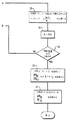
図2には、本発明の一つの実施例の方法論を遂行するためのステップが流れ図形式にて示される。図面に示されるように、このプロセスは、網内のセットの仮想経路に対する初期のルーティングの決定および容量の割当てから開始される(ステップ10)。このプロセスの次のステップ(ステップ20)として、網閉塞確率および網感度が、このステップへの入力として提供される仮想経路ルーティングおよび容量割当て、つまり、最初に、ステップ10において決定されたこれら初期係数、に基づいて決定される。次のステップ(30)において、閉塞確率および申し出負荷と関連で、網感度が、網性能基準に対して評価される。次に、ステップ30における評価の結果を、前の反復に対する結果(あるいは最初の反復の場合は任意の値)と比較するための判定ステップ(ステップ40)が遂行される。増分変化が閾値量よりも小さな場合は、このプロセスは終了し、その入力仮想経路ルーティングおよび容量割当てが最適なものとして受理される。増分結果が閾値量を超える場合は、さらなるステップ(ステップ50)が遂行され、ここで、ステップ20において決定された閉塞確率および網感度に基づいて新たなセットの仮想経路ルーティングおよび容量割当てが生成される。この新たな仮想経路ルーティングおよび容量割当てが、次に、このプロセスの、次の反復に対するステップ20への入力として提供される。
【0034】
2C.スイッチ容量に起因する制約
本発明の方法においては、論理網設計最適化プロセスに、追加の制約を導入することが可能である。つまり、網ノードの所に位置するスイッチの呼の設定の際にシグナリングタスクおよび処理タスク(例えば、帯域幅空き状態を知るためのデータベーストランザクション)を扱う能力に起因する制約を導入することが可能である。周知のように、個々のスイッチは、呼を、特定の最大の速度まで処理することができるのみである。このような制約は、伝送リンクのトラヒック処理能力によって含意される制約とは、全く異なるものである。後者の制約については、本発明の方法論の前に説明された定式化によって既に考慮ずみである。ただし、多数のトラヒックストリームが一つのスイッチに収束するような幾つかのケースにおいては、そのスイッチの処理能力が運ばれるトラヒックを決定する上での拘束制約(binding constaint)となるような状況が発生し得る。本発明の方法論においては、特に後に説明されるソフトウエア実施例として実現される場合、このようなスイッチの呼処理容量に起因する制約が、式(2.5)によって記述される全体的な網性能最適化手続きに導入される。
【0035】
網内の各スイッチ(つまり、ノード)に対して、Кiが、ノードiの所から発信される、あるいはこれを通過する(ただし、ここに終端はしない)セットの全てのルートを表すものとする。これらセットは、全てのサービスsおよび発着ペアσに対して、元のルートセットК(s、σ)に関して周知のセット演算(set operations)を適用することによって簡単に得ることができる。Piが、スイッチiに対する最大呼処理速度あるいは容量を表すものとする。すると、これらスイッチ制約は、以下の線形形式にて表現することができる:
【数8】
【0036】
2D.帯域幅割当て
網最適化手続きが完了した段階で、本発明の方法論のさらなるステップとして、帯域幅が網設計を構成する仮想経路の間に割当てられる。前述のように、トラヒックストリーム(s、r)に対する仮想経路は、そのストリームに対する発信元と宛先を接続する網リンクのリストおよびこれらリンクの各々に対する帯域幅割当てから構成される。最適化手続きが完了した時点で、以下のデータ:つまり、(i)vsl;r、つまり、リンクlに申し出られたストリーム(s、r)の薄くされた(シニングされた)負荷(後の式(3.9)を参照)、および(ii)Bsl、つまり、リンクl上のサービスsの損失確率(後の式(3.2)を参照)が利用可能となり、本発明のソフトウエア実施例からの出力として提供される。これら二つの量、vsl;rおよびBsl、並びに、セル当たりの帯域幅要件、dslから、しばしば、逆アーラン(Inverse Erlang)と呼ばれる単純かつ周知の手続きを使用して、リンクl上のストリーム(s、r)に対するコンパティブルな帯域幅割当てが得られる。Csl;rがこの量を表すものとする。
こうして、ストリーム(s、r)に対する仮想経路は、シーケンスのリンク、lから構成され、各リンクには、公称容量、つまり、Csl;rの帯域幅が割当てられることとなる。
セクション2においては、本発明の方法が、発明の全体としての枠組みからの観点から説明された。以下のセクション3から8においては、本発明の方法の様々なステップについて、特に、これらステップに対する底辺に横たわる方程式およびアルゴリズムの展開に関して、より詳細に説明される。
【0037】
3.網分析
3A.固定点方程式の展開
これら固定点方程式は、周知のリンク独立想定(link independence assumption)に基づいて導かれる。この想定の下では、リンクlを使用する各ルートは、リンクlへの負荷に寄与するが、これは、そのルート内の全ての他のリンクによる独立的なシニング(independent thinning)によって低減することができる速度を持つポアッソン分布(Poisson)を持つ。Bslがリンクl上のサービスsの呼の損失確率を表すものとする。前のセクションにおいて説明されたように、リンクlは、容量Clを持ち、サービスsは、帯域幅dslを要求する。vslが、リンクlに申し出られたサービスタイプsの呼のシニングの後に得られた低減された負荷を表すものと想定し、また、
【数9】
【数10】
【0038】
リンク独立想定が使用された場合は、低減された負荷は、以下によって与えられる:
【数11】
【数12】
【0039】
方程式(3.4)を解くためには、逐次近似の方法を使用することがてきる。この方法は、初期値vl(0)から開始され、i=0、1,2、...に対して、収束基準が満足されるまで反復される。つまり:
【数13】
【数14】
3B.暗黙コストの決定
式(3.2)およびLsに対する明示表現(例えば、Kaufman,id.を参照)から、以下の関係が得られる:
【数15】
【0041】
申し出負荷ρsrに対する収益Wの感度は、収益が固定点方程式を解決することによって計算される場合、以下のようになる:
【数16】
【数17】
【数18】
【0042】
式(3.3)から、リンクlに申し出られたサービスタイプsのシニングされた負荷は、以下となることに注意する:
【数19】
【0043】
式(3.10)内の方程式系に対する完全解(exact solution)の複雑さは、O(S3L3)となることに注意する。
リンク容量に対するリンク上の損失の感度もまた興味深いものがある。線形補間を使用して、以下の感度の関係式(sensitivity relationship)を定義することができる:
【数20】
【数21】
【0044】
4.単一リンク網分析
セクション3の網方程式の解を見つけるための本発明の漸近近似方法論(asymptotic approximation methodology)に向けての発展的段階として、最初に、単一リンク網(single link network)の完全分析(exact analysis)について説明され、次に、この分析を簡素化するために、一様漸近近似(uniform asymptotic approximation,UAA)の適用について述べられる。続くセクション5においては、UAAが、一つ以上のリンクを持つ網に適用される。この簡素化されたケースによって得られる結果の構造的形式(structural forms)は、洞察に富むものであり、次のセクションにおいて展開されるように、マルチリンク網に対する一般化を示唆するものである。
ここでの分析は、単一リンクの網に対してのみ向けられるために、リンクインデックスl、および、ルートインデックスrは、このセクションを通じて省略される。従って、このセクションにおいては、サービスタイプsの単一リンク網への申し出トラヒックは、vsとなる。
【0045】
4A.完全分析
主要な、完全結果(exact results)は、以下のように要約できる、つまり:
単一リンク網に対しては、収益感度は、以下によって与えられる:
【数22】
【数23】
【数24】
4B.UUAの適用
このサブセクションにおいては、UAAの単一リンクの場合の損失確率への適用について要約される。ここでは、以下が想定される:
【数25】
【数26】
【数27】
【数28】
【数29】
【数30】
BS〜bSB,(s=1,2,....,S) (4.12)
が成立する。これら近似は、それぞれ、オーバーロード体制、クリティカル体制、およびアンダーロード体制に対応する、0<z*<1であるか、z*≒1であるか、あるいは、z*>1であるかに関係なく成立する。vtに対するBsの導関数に対する類推的な近似から、以下の命題が得られる:
つまり、
【数31】
【数32】
【0047】
式(4.12)および(4.14)を、式(4.13)内で使用することによって、単一リンク網における暗黙コストに対する漸近近似が以下のように得られる:
【数33】
【数34】
【0048】
5.UAAに基づく網分析
セクション3および4にて説明された背景知識があれば、UAAによって得られる網に対する固定点方程式および暗黙コストに対する方程式を説明するのは簡単である。
【0049】
5A.固定点方程式
網に対する固定点方程式(fixed point equations)は、式(3.4)に与えられている通りである。関数Ψは、修正を必要とせず、式(3.3)によって定義されている通りである。vlをBlにマッピングする関数Φlは、勿論、UAAがリンク分析に対して使用される場合は、かなり異なる。この手続きは、方程式(4.5)から(4.12)に与えられている通りである(ここでは、リンクインデックスが再度導入される)。より具体的には、関数Fl(z)およびVl(z)が、式(4.5)のように定義され、最小Fl(zl *)が起こるポイントzl *が式(4.6)において計算され、bslおよびBlが式(4.7)および(4.8)において計算され、最後に、
Bsl=bslBl
が計算される。
要約すると、上の手続から関数:
【数35】
式(3.5)において説明された固定点方程式を解くための反復的な逐次近似手続きがここでも使用される。網設計および最適化問題は多数の網解(network solutions)を必要とるすために、単一リンクの分析における複雑さのO(C)からO(1)への低減は、計算負担が大幅に低減されることを意味する。
【0050】
5B.暗黙コスト
方程式(3.10)は、暗黙コストによって満足される線形方程式の系を与える。式(3.10)内で、式(4.14)にて与えられるUAAによって得られた表現を置換することによって、以下が得られる:
【数36】
【数37】
【数38】
【数39】
全てのt(1≦t≦S)およびl(1≦l≦L)に対して、
【数40】
【数41】
【0051】
方程式(5.7)は、{ξl}内の方程式の完全系(complete system)である。この方程式の系内のパラメータ、つまり、{vsl;r}、{Bsl}および{ask}は、全て、セクション5Aにおいて説明された固定点方程式の解から直接に得ることが可能である。方程式(5.7)は、単にL個の線形方程式の系であるという特性を持つ。方程式(5.7)の解がいったん得られると、全ての暗黙コスト{ctl}を方程式(5.6)から得らることができる。暗黙コストを得るためのこの手続きは、複雑さO(L3)を持ち、また、これがサービスの数から独立していることは、本発明の方法の一つの重要な長所である。
【0052】
6.ハイブリッド網方程式系
殆どのリンクはUAAの適用に適当であるが、幾つかの少なくないケースにおいては、網が、十分に大きくなく、従って、漸近分析を適用することができない幾つかのリンクを持つことが見込まれる。従って、このようなケースを扱うための手続きが本発明のもう一つの実施例として提供される。完全分析と漸近分析とのハイブリッドであるこの手続きは、閉塞確率並びに暗黙コストに対する方程式の閉じた系を提供する。ここで、
LE △ が完全分析を適用されるセットのリンクを表し、
LA △ がUAAを適用されるセットのリンクを表すものとする。
各リンクは、これらセットの一つの要素を持つ。
【0053】
最初に、暗黙コストに対する線形方程式の系について考える。方程式(5.5)および(5.5)から、l∈LAに対しては、
【数42】
【数43】
上の考えは、自然に、閉塞確率に対する非線形固定点方程式(nonlinear fixed point equations)のハイブリッド系へと拡張する。式(3.4)において、
【数44】
v=Ψ(B)
となり、率直に逐次近似の反復法が適用できる。
【0054】
前の4つのセクションにおいて示された様々な方程式の詳細な誘導、並びに、漸近方程式精度に関する追加の数的結果は、発明人の上で言及された最近の論文[D.Mitra,J.A.Morrison,and K.G.Ramakrihnan,“Unified approach to multirate ATM network design and optimization",1995年11月出版予定]において与えられていることに注意する。
【0055】
7.フロー境界
本発明の方法論の目標は、網性能を最適化すること、あるいは、一つの好ましい実施例においては、その代理(関数)としての“網収益(network revenue)”を最適化することにある。網収益関数(2.4)は、通常は、凹関数ではない。収益を最大化するためのこれら手続きによって得られる解の品質を測定するためには、境界を設けることが必要とされる。最も単純な上限は、トラヒックプロセスからそれらの確率性(stochasticity)をはぎ取ることに基づくものである。つまり、これらプロセスを、時間を通じて一様の速度を持つ決定論的(deterministic)な流体あるいはフロープロセスとみなす方法である。このフレームワークにおいては、網収益は、一般線形計画問題(general linear programming problem)であるマルチレート、マルチコモディティ最大フロー問題を解決することによって最大化される。この問題に対する解は、WF *にて表され、これが、式(2.5)の解から得られる最大網収益W*の上限である。
【0056】
このフロー問題は、従って、以下のように指定することができる:
【数45】
【数46】
【0057】
8.適応方法論
一般ハイブリッド形式にて表された暗黙コストに対する方程式(6.1)および(6.2)は、以下の形式に書くことができる:
Ax=y (8.1)
ここで、xの要素は、ξl(l=∈LA)およびcsl(l∈LE;s=1、2、...、S)である。セクション6において、全ての暗黙コストをxから得ることができることが示された。方程式(8.1)は、(要素的に)y>0およびA≧0であるという重要な特性を持つ。また、暗黙コストの物理的解釈からx≧0である。線形方程式(8.1)の系のこの非負性が、解に対する反復アルゴリズムの基礎である。このアルゴリズムは、幾つかの魅力を持つ。特筆すべき一つの魅力は、これが、最急上昇手続きによる網最適化に良く適合することである。つまり、この手続きにおいては、式(8.1)が、前のインスタンスから大きく異ならない(A、y)に対して反復して解かれることが要求されるが、この反復手続きを前の解から開始することによって、反復の回数が、場合によって、大幅に削減される。これは、リアルタイム用途、例えば、仮想経路の論理網を変動するトラヒック状態に適応される用途においては、明白な長所となる。
【0058】
発明の基本的方法論を、トラヒック状態の変動に合わせて適応させるための適応アルゴリズムは、EMアルゴリズムの適用である。このEMアルゴリズムについては、VardiおよびLee[Y.Vardi and D.Lee,“From image deblurring to optimal investments:maximum likelihood solutions for positive linear inverse problems",J.R.Statist.Soc.B,55(3):569-612,1993;Y.Vardi,“Applications of the EM algorithm to linear inverse problems with positivity constraints“,Preprint,1994]において詳細に説明されているが、これらの論文からの要点がここで簡単に総括される。最初に、適当なスケーリングによって、式(8.1)が、統計的推論のための適当な形式にされる。ここで、xおよびyは、確率ベクトルである。つまり、総和されて1となる非負の要素を持ち、Aのカラムの総和は、1となる。式(8.1)を解くことを、不完全データ(incomplete data)からの推定と比喩的に解説するために、X、Y|XおよびYが、パラメータx、Ax(Aのカラムx)およびyを持つ多項式として分布するものと考える。さらに、比喩を完結するために、(X、Y)を“完全(complete)”データであるものと考え、その投影Yを“不完全(incomplete data)”(観察された)データであるものと考える。EMアルゴリズムが、ここで、この正準推定アルゴリズム(canonical estimation algorithm)に適用される。この反復アルゴリズムによって生成されるシーケンスは、常に、反復された確率ベクトルと目標確率ベクトルとの間のKullback-Liebler情報発散(information divergence)を最小化するポイントに収束する。さらに、この収束は、収束点を除いては、距離が厳密に低減していくという意味において、単調である。最後に、非負制約が手続き全体を通じて満足される。
式(8.1)を解くためのEMアルゴリズムは、
【数47】
【0059】
9.発明のTALISMANソフトウエア実現
多層網設計問題を解くための本発明の上に説明された方法を実現するためのソフトウエアシステムが開発された。このソフトウエアシステムはTALISMAN(Tool for AnaLysIs and Synthesis of Multirate ATM Networks)と呼ばれる。現在の実施例においては、TALISMANは、C++言語にて書かれ、本発明の方法論の階層的性質およびその分析的構造を反映してモジュール化されている。層1においては、基本リンクレベルでの損失確率およびそれらの偏導関数の分析が遂行される。層2においては、本発明の好ましい実施例のシャドウコスト(shadow cost)の解が解かれ、これに対する感度計算が遂行(実現)される。層3においては、層1および2の結果を使用する最適化アルゴリズムが実現される。
【0060】
TALISMANのソフトウエアアーキテクチャが図3に示される。このアーキテクチャは、3つの協力するUNIX(登録商標)プロセスから構成される。最初に、パーサ(parser)プロセスによって分析される網に対する網トポロジファイルが読み出され、様々な網記述ステートメントが解析される。これは、次に、網トポロジファイルをオブジェクトファイル内にコンパイルするが、このオブジェクトファイルは、網トポロジを一段とコンパクトに符号化する。パーサプロセスは、また、仕様ファイルを読み出すが、この仕様ファイルは、TALISMANの全ての層内の解決戦略に影響を与えるアルゴリズムパラメータを含む。TALISMANの一般バージョンにおいては、パーサプロセスは、また、amplプログラムを読み出すが、これは、TALISMANによって解かれるべき最適問題の符号化を行なう。ただし、本発明の方法の好ましい実施例に向けられたTALISMANの特定のバージョンにおいては、最適化問題は、陰(implicit)関数であり、従って、この第三番目の入力は存在しない。パーサプロセスは、これらオブジェクトモジュール、アルゴリズムパラメータおよび一般形式の最適化問題を、最適化(optimizer)プロセスにパスする。このプロセスは、TALISMANの第三の層に対応する。最適化プロセスの機能は、採用されるTALISMANのバージョンに依存する。ここに示される本発明の方法論の好ましい実施例に向けられた、以降、TALISMAN-LD(Logical Desingの略)と呼ばれるTALISMANのバージョンに対しては、この最適化プロセスは、本発明の方法論の収益最大化プロセスを実現する。TALISMAN-LDに使用される最適化アルゴリズムに対する疑似コードは、前にセクション2Aにおいて示された通りである。
【0061】
最適化アルゴリズムの各反復において、与えられた現在のルーティング(つまり、与えられた現在のρs,r)に対して、リンクレベルでの閉塞確率およびそれらの偏導関数を解くことが必要となる。網の分析が要求されるたびに、網解決(network solver)プロセスが、最適化プロセスによって読み出され、最適化プロセスに対して、
.オブジェクトモジュール
.現在のトラヒックストリームの値ρs,rおよび
.アルゴリズムパラメータの値
がパスされる。この網解決プロセスは、本発明の方法論に対する問題構造の層2および3を実現する。
【0062】
図4には、層3、つまり、リンク層の実現を解説する流れ図が示される。この層は、上のセクション3の方程式(3.5)によって与えられる固定点方程式を実現する。最初に、反復カウンタkが0にセットされる。次に、各ルートに対する現在の申し出トラヒックストリーム(ρs,r)、並びに、停止公差(stopping tolerance)εが読み込まれる。ステップ2において、全ての閉塞確率が0にセットされる。ステップ3において、各サービスクラス内の各リンクに対する現在の申し出トラヒックが、シニングが行なわれないものと想定して計算される。このセットのリンクに対する申し出トラヒックの測定値、並びに、リンク帯域幅を使用して、解決技法の選択に関する決定がなされる。この決定の結果として、リンクセットLが、二つのサブセットLEおよびLAに分割されるが、これらは、それぞれ、完全分析されるべきリンク、および漸近分析アプローチが適用されるべきリンクに対応する。ステップ5において、漸近分析において使用される共通項(common term)、つまり、Blが0に初期化される。これによって初期化フェーズが完了する。このアルゴリズムの反復フェーズにおいては、l∈LAに対する共通項Blが計算され、次に、s∈Sおよびl∈LEに対するBslが計算される。BlおよびBslのこれら値は、次の反復への対応を示す(k+1)のスーパースクリプトを持つ。ステップ8において、閉塞確率における最大相対変化(largest reltive change)が決定される。ステップ9において、各サービスクラスについて、漸近リンクに対する閉塞確率が、方程式(4.7)に従って計算される。ステップ10において、次の反復に対する新たな申し出トラヒックが、方程式(3.2)を使用して計算される。次に、ステップ11において、反復カウンタが1だけ増分される。ステップ12において、この量が停止基準と比較され、収束が達成されてない場合は、ステップ6にループバック(帰還)する。達成されている場合は、この反復プロセスは終了する。Bslの収束された値が手に入ると、ステップ13および14に示されるように、閉塞確率の偏導関数を計算することができる。これによって、層3の実現が完結する。
【0063】
層2の実現は、シャドウコストに対する解を解くことに関する。最初に、線形方程式の系(前のセクション6の方程式(6.1)および(6.2))の希薄行列(sparse matrix)が構成される。次に、この線形方程式の系を解くために、EMアルゴリズムが使用されるべきか、あるいは、直接因数分解(direct factorization)アルゴリズムが使用されるべきかが決定される。後者の場合は、行列が、上側三角行列と下側三角行列に因数分解される。次に、この線形方程式の系の解が、前向き置換(forward substitution)およびこれに続く後向き置換(back substitution)を使用して得られる。前者の場合は、EM反復アルゴリズムが、オプションとしての開始解(starting solution)と共に、呼び出され、この線形方程式の系が解かれる。この線形方程式の系の解が得られたのちに、目的関数および勾配が評価され、最適化プロセスに返される。
【0064】
10.発明の実験的な適用
TALISMANソフトウエアシステムを使用して、本発明の方法論を仮想的な網に適用するための幾つかの計算に関する実験が発明人によって遂行された。以下に、これら実験およびこれからの結果について、幾つかのサブセクションに分けて説明される。セクション10Aにおいては、これら実験がそれに対して行なわれた網の基本的な事項について説明される。セクション10Bにおいては、3つの異なるルートセットに対する収益最大化問題からの結果が示されるが、これらルートセットは、受理可能なルート(admissible route)内のホップの数に基づいてパラメータ化された。セクション10Bにおいては、さらに、対応するフロー問題を解くことによって得られた収益境界(revenue bounds)が与えられる。最後に、セクション10Cにおいて、(それらの相互トラヒックの重さから選択された)ペアのノード間のトラヒックが1パーセントのステップにて変化されたときの、全ての暗黙コストを計算するための要求されるEMアルゴリズムの反復の回数についての結果が示される。
【0065】
10A. 実験網
図5に示されるこの仮想網は、8(N=8)個のノードを持ち、図2に示されるように、10のペアのノードが、直接に接続される。これら各ノードペアは、トラヒックを反対方向に運ぶ2つの単方向リンクによって接続される。こうして、この網は、20(L=20)の単方向リンクを持つ。単方向リンクの典型的な帯域幅は、45Mbpsであるが、例外として、Argonne(3)とPrinceton(4)、並びに、Houston(8)とAtlanta(7)を結ぶ双方向リンクがあり、これは、90Mbpsの帯域幅を持つ。
6(S=6)のサービスが存在する。これらサービスと関連する伝送速度は、それぞれ、16、48、64、96、384および640Kbpsであり、全てのリンクを通じて一様であるものと想定される。サービス1は、音声であり、サービス2から5は、データであり、サービス6は、ビデオであるものと想定される。便宜的に、リスケーリングし、16Kbpsが帯域幅単位であるものとする。テーブル1は、サービス帯域幅をこの単位にて示すが、これは、従って、ds≡dsl(s=1、2、...、S)を定義する。また、45Mbpsおよび90Mbpsのリンク帯域幅は、それぞれ、2812および5625単位に相当する。従って、l=1、2、...、Lに対して、Cl∈{2812,5625}となる。
【表1】
【0066】
外来申し出トラヒック強度の記述をコンパクトにするために、サービスs( s=1、2、...、S)に対する、N×Nの、ベーストラヒック強度マトリックス(base trafic intensity matrix)T、および、乗数msが採用される。こうして、msTijは、ノードiからノードjまでのサービスsの申し出トラヒック強度、つまり、Λsσ/μsσを与え、ここで、σ=(i、j)である。トラヒック強度に対する測定のユニットは、呼である。マトリックスTが、テーブル2に示され、乗数{ms}がテーブル3に示される。
【0067】
【表2】
【表3】
申し出トラヒックは、対称性であることに注意する。また、
【数48】
【0068】
10B.収益最適化ルーティング
ここに示される結果は、TALISMANソフトウエアシステムを実行することによって得られたものであるが、これは、リンク分析のために、漸近方程式か、あるいは完全分析の、いずれか1つを自動的に選択する様々な“エクスパートシステム”を含む。説明を通じて、ルートr上のサービスsによって単位時間に運ばれた呼によって獲得される収益は、全てのrに対して、
esr≡ds (10.2)
として設定される。
【0069】
これら結果は、3つの異なるルートセットに対するものである。各ケースにおいて、これらルートセットは、以下に説明される単純なアルゴリズムによって生成される。
【数49】
【0070】
テーブル4には、TALISMANによる収益最適化からの結果と、フロー境界を与える線形プログラムを解くことによる結果とが、比較して示される。このテーブルには、また、閉塞確率に関するデータも示される。閉塞確率は、帯域幅単位(呼単位ではない)を使用して、申し出帯域幅トラヒックと、運ばれた帯域幅トラヒックに基づいて計算された。申し出帯域幅トラヒックと、運ばれた帯域幅トラヒックは、それぞれ、Ωofferredと、Ωcarriedによって与えられ、ここで、
【数50】
Ωofferred=21,607 (10.5)
となる。方程式(10.2)のために、この量は、閉塞が存在しないときに確保される収益でもある。
【0071】
【表4】
テーブル4は、また、各ストリーム(s、σ)に対する申し出トラヒックを、ルートセットК(s、σ)内の全てのルート上に一様にバランスさせることに基づいてルーティングする場合の性能基準を明らかにするが、この基準もまたTALISMANから得ることができる。一つの重要な特別のケースにおいては、申し出トラヒックが、ルートを通じて一様に、最小数のホップにて割られる(“最小ホップルーティング(min-hop rputing)”)。このケースにおいては、収益は、19,167となり、閉塞確率は、11.3%となる。テーブルのデータは、性能は、最適化ルーティングが使用された場合、ルートセットを大きくすると、向上することを示す。これとは、対照的に、一様負荷の場合は、ルートセットを大きくすると、長く、従って非効率なルートに対して過剰な負荷が申し出られるために、逆の影響が現われることに注意する。
前述のように、この網収益関数は、凹関数であり、従って、セクション2によって与えられる最適化アルゴリズムに対する最急上昇は、初期条件に依存する局所最大に終端するが、テーブル4内の“最適ルーティング(Optimal Routing)”の項目の下に示される結果が、様々な初期条件から得られた中の最良なものである。
【0072】
10C 適応
ここでは、変動するトラヒック状態の下で完全暗黙コスト(方程式(3.10)を参照)を計算するための最適化アルゴリズムの性能に関する結果が示される。3つのリナリオについて考察された。第一のシナリオにおいては、Palo Alto(2)からCambridge(5)までのトラヒックが、6つの全てのサービスに対して、基本トラヒックの1%のステップにて、増分された。一連の反復内の相対差のベクトルのL∞ノームが、10−4以下になるまで、反復の回数を増加して計算が行なわれた。テーブル5には、この結果が示されるが、これから、各インスタンスにおいて、最大3回の反復が要求されることがわかる。これがどれほど優れているかの評価は、任意の初期条件から開始して全ての暗黙コストを計算するために要求されるEMアルゴリズムの反復回数、約23回と比較すると、明らかである。
【表5】
【0073】
テーブル6は、Argonne(3)からCambridge(5)までのトラヒックの場合の、全てのサービスが、基本トラヒックの1%のステップにて、最高10%まで、減分された場合の第二のシナリオに対する結果を示す。最後に、テーブル7は、第一と第二のシナリオが結合された場合、つまり、Palo Alto(2)からCambrige(5)までのトラヒックが増加され、同時に、Argonne(3)からCambride(5)へのトラヒックが減少されるときの結果を示す。
【表6】
【0074】
【表7】
【0075】
結論
マルチレートATM網の設計および最適化に対する、非漸近分析法と漸近分析法を統合して使用する、方法論が提供された。漸近技法は、出現中のATM網の固有の特徴である異なる速度の複数のサービスが存在する状況下で、大きな帯域幅のリンク、を扱うときの計算の複雑さを解消することを意図する。
【0076】
本発明の現在の実施例が詳細に説明されたが、特許請求の範囲によって定義される本発明の精神および範囲から逸脱することなく、様々な修正、代替、置換が可能であることを理解されるものである。より具体的には、特に、本発明は、主として、ATM技術に基づく一つの好ましい実施例との関係で説明されたが、本発明の方法および概念は、パケット指向の通信網にも適用できることに注意すべきである。
【図面の簡単な説明】
【図1】本発明の新規の方法が実施されるデータ網を示す。
【図2】本発明の一つの実施例を流れ図にて示す。
【図3】本発明のソフトウエア実現に対するアーキテクチャ構造を示す。
【図4A】本発明のソフトウエア実施例の実現ステップを流れ図にて示す。
【図4B】本発明のソフトウエア実施例の実現ステップを流れ図にて示す。
【図5】本発明の方法論の動作のシミュレーション結果を示すために使用された一例としての網を示す。
【符号の説明】
105−1,105−2,105−3,105−4,105−5 通信デバイス110 網
120−1,120−2,120−3,120−4 ユーザ網インタフェース
130−1,130−2,130−3,130−4,130−5 ノード
140−1,140−2,140−3,140−4,140−5,140−6,140−7,140−8 リンク[0001]
BACKGROUND OF THE INVENTION
The present invention relates to communication networks carrying multi-service traffic, and more particularly to a method for logical network design in such communication networks.
[0002]
[Prior art]
A network transmits information (eg, data, voice, text, video, etc.) to a communication device (ie, a device for inputting and outputting information, eg, a computer terminal, multimedia workstation, It is the main means for exchanging or transmitting between a fax machine, printer, server, telephone, video phone, etc.).
[0003]
A network typically consists of switching nodes connected by links to each other and to communication devices. Each link has an individual characteristic bandwidth, ie, link capacity. Information entered into the network from a communication device can have any format, but is typically formatted into a fixed length packet or cell. When information is to be exchanged between two communication devices, a path is established in the network for connecting nodes associated with the devices (hereinafter referred to as a source node and a destination node).
[0004]
In many networks, between a specified source and destination, a set of physical paths in the network (ie, source and destination nodes, possibly one or more intermediate nodes, and contained nodes). A given communication stream is carried over a path consisting of connecting links (the term “communication stream” is exchanged between communication devices connected to the network at the source and destination nodes. These routes from the origination of a set to the destination, characterized by having a predetermined bandwidth for each route, are usually referred to as “logical” or “virtual” routes. There are often several of these virtual paths along all or part of a physical path in the network, typically at first Several different physical routes are selected to form a virtual route, but once this virtual route is set, the physical route thus selected is typically set for that communication stream. Stay as it is.
[0005]
Also note that these multiple logical paths, and one or more logical sub-networks formed by grouping these logical paths, result in both of the two characteristic networks. . That is, the first network has a fixed set of logical sub-networks to provide to various users of that network, and in the second network it constitutes that network. The logical subnetwork to be resized is re-dimensioned to handle the changing traffic requirements.
[0006]
One important element of logical network design is the process of selecting a set of physical paths that have sufficient capacity to carry the estimated traffic of the communication stream through the network. This process includes network topology, currently available resources (eg, buffer space and link capacity within the node), and quality of service promised to network users (eg, guaranteed bandwidth or maximum cell loss). Consider various factors such as probability.
[0007]
Asynchronous Transfer Mode (ATM) is a networking protocol often applied within the networks described above, which is designed to efficiently support high-speed digital voice and data communications. A high-speed communication network based on ATM integrates many services with different traffic characteristics. In other words, various traffic characteristics are integrated from a constant bit rate (characteristic) to a highly bursty variable bit rate (characteristic). The idea of effective bandwidth is important for translation from variable bit rate traffic used in the context of buffered transmission to constant bit rate traffic in transmission facilities that do not have buffer. It is a concept. This concept of effective bandwidth is described in detail in US patent application Ser. No. 08/506160, “A METHOD FOR ADMISSION CONTROL AND ROUTING BY ALLOCATING NETWORK RESOURCES IN NETWORK NODES,” pending examination by one of the inventors. .
[0008]
Using this concept of effective bandwidth translation, ATM networks are considered multirate circuit-switched loss networks, at least for the purpose of handling calls. In this network, the description of each service includes a characteristic bandwidth requirement or characteristic rate for each link carrying that service. On the surface, there is a lot of traditional work on single-rate, circuit switched network design [in this regard, eg, A. Girard, Routing and Dimensioning in Circuit-Switched Networks, Addidon-Wesley, 1990, and GRAsh, RHCardwell, and RPMurray, “Design and optimization of networks with dynamic routing”, Bell Syst. Tech. J., 60 (8): 1787- 1820, Oct. 1981] appears to provide an opportunity for network analysis using conventional techniques. However, a close examination reveals that network design issues, particularly those related to multi-rate, multi-service characteristics associated with ATM networks, and design issues related to capacity allocation and routing for virtual routes, are substantially different from those handled by the prior art. It can be seen that there are various characteristics that make it more difficult to handle.
[0009]
[Problems to be solved by the invention]
There are three characteristics that need special attention. First, in contrast to permanent virtual circuits, switched virtual circuits have random arrival times and random retention times, which necessitates a design procedure that takes these randomities into account. The second characteristic relates to the size of the network link. As an example, consider a 150 Mbps bandwidth link that carries traffic for various services with a minimum service rate of 8 Kbps. In the circuit switched model, such a link is considered to have 18,750 circuits, considering that the smallest service speed is equivalent to a single circuit. Since high speed optical transmission links can carry 2.5 Gbps, the link capacity in the circuit, generally denoted as C here, is expected to be very large in future networks. (Note that link capacity C can be expressed equivalently in bandwidth). The second (third) noteworthy characteristic is that the number of services S, especially in the near future, as the “information superhighway” is becoming increasingly realistic is 10-25. In the medium term, it is expected to increase further. Due to the large number of capacity and service parameters that current and anticipated future multi-service, multi-rate networks, eg, ATM networks, feature, traditional network analysis methods will be applied to these networks. It is considered difficult to make this attempt from the viewpoint of the computer's tracking ability.
[0010]
[Means for Solving the Problems]
A method for network optimization based on multirate circuit switching analysis is disclosed. According to the method of the present invention, the network loss probability is determined as a solution of a set of fixed point equations, and the sensitivity of the network performance as a function of the offered load and loss probability is determined as a solution of the set of linear equations. Both the fixed point equation and the sensitivity equation are both in terms of network loss probability and network sensitivity, because the computational complexity of solving this is on the order of impossible to compute a complete solution. Thus, an asymptotic approximation is applied to give these solutions. A global optimization procedure is then applied using an iterative steepest climb procedure to obtain a set of virtual route routing and capacity allocation.
[0011]
As another embodiment of the present invention, an integrated hybrid approach is provided that allows cooperative use of asymptotic and non-asymptotic (perfect) computations. As yet another embodiment of the present invention, a methodology is provided for performing the network optimization procedure of the present invention in situations where traffic conditions vary.
In addition, software embodiments of the present invention are provided for automatically performing the optimization methodology of the present invention for both static and dynamic traffic situations.
[0012]
DETAILED DESCRIPTION OF THE INVENTION
Notation and terminology
The following description is represented in part by algorithmic and symbolic representations of operations on data bits within a computer system. As can be appreciated, these algorithmic descriptions and representations are the means commonly used by engineers in the computer processing field to communicate the contents of their work to other engineers in the field.
[0013]
The term algorithm used here (and in general) can be viewed as a self-contained series of steps to derive the desired result. These steps usually involve manipulation of physical quantities. Usually, although not required, these physical quantities take the form of electrical or magnetic signals that can be stored, transferred, combined, compared, and otherwise manipulated. These signals are often described as bits, values, elements, symbols, characters, terms, numbers, etc., for convenience of explanation and to suit normal usage. It should be emphasized, however, that these and similar terms are to be associated with the appropriate physical quantities, and that the terms are merely convenient labels applied to these physical quantities.
[0014]
Introduction
The following detailed description is divided into a plurality of sections.
[0015]
1. environment
FIG. 1 shows a network environment in which the method of logical network design according to the present invention is performed. The
[0016]
In the design and operation of information networks, eg,
[0017]
In the case of a multi-service network, each service typically has an associated virtual path (defined) with a specified bandwidth capacity configured for each serviced source and destination node pair. The virtual path for a particular service offered between endpoints can also be implemented as two or more serially connected virtual paths, in which case the switched connection is the virtual path connected in series. Note that this happens at an intermediate node that represents the endpoint for). For a given service, a specific communication transaction (hereinafter called calls) between the serviced communication device at the originating node and the communication device at the destination node is performed by the originating node. Occupies a virtual connection or a virtual circuit in a virtual path connecting the destination node and the destination node. As will be apparent, the sum of the bandwidth requirements for all virtual circuits in use in a virtual path at any point in time must be less than or equal to the bandwidth set for that virtual path.
[0018]
Logical partitioning of physical networks following the concepts described above is generally more efficient in network resources compared to using a separate physical network or physical path for each user or service. Real use. However, because each logical path or sub-network has a certain amount of dedicated bandwidth, one or more virtual paths or sub-networks will have much lower levels of traffic than the logically divided bandwidth capacity. It is quite possible that a situation will occur where all the bandwidth available to the other logically segmented part (using the same physical link) will be blocked because it is in use. It is done. One important objective of the methodology of the present invention is to achieve a close match between the transmission requirements of certain communication streams and to determine the size of the virtual path used by these communication streams.
In the remainder of this section, such logical partitioning within the network is described in terms of virtual paths (or virtual circuits where appropriate), except that the principles shown in this description are: It should be understood that the same applies to virtual sub-networks.
[0019]
To describe the operation of
[0020]
In selecting a viable network route for the virtual path in which the requested virtual circuit is implemented, some or possibly all of the nodes 130-i are associated with at least one predetermined size buffer. And that each link 140-k has a predetermined traffic processing capacity described in terms of the bandwidth or circuit equivalent value associated with it (usually such a The buffer provides temporary memory for cells in transition between communication devices and is used to wait for sufficient bandwidth to be available on later links along that path) . Therefore, before determining the set of physical paths that make up the virtual path associated with the requested service, the potential to connect the network resources required by the virtual path and the endpoints to be serviced by the virtual path. It is necessary to know both the network resources that are available along all the physical paths that are available to the public. Obviously, routing such a virtual route through the network requires the availability of network resources that can be used exclusively for this virtual route throughout the duration of the associated service.
[0021]
2. Explanation of the methodology of the invention
The inventive methodology is described herein in terms of optimizing network performance in a preferred embodiment of the present invention, namely, ATM network design. More particularly, the focus in this embodiment of the inventive methodology is the sizing and routing of virtual routes within a multi-service network (where each virtual route is offered between a specific source and destination). As well as the specific service) and the speed of the offered traffic for the various routes connecting the source and destination node pairs in such a way that optimum network performance can be achieved. In this embodiment, network revenue optimization is selected as a proxy (function) for optimal network performance. Obviously, the purpose of this embodiment of the methodology of the present invention, from another perspective, is to determine the optimal size of the virtual path network.
[0022]
One fundamental aspect of the methodology of the present invention is the systematic introduction of asympotics at various stages of computation in multirate network design. In addition, an integrated hybrid framework is provided that allows asymptotic and non-asymptotic techniques (sometimes referred to herein as “exact” techniques) to cooperate and interpolate with each other. The central element in the asymptotic approach is the uniform asymptotic approximation (UAA) developed by the two inventors for the analysis of a single link. This analysis is described in "Erlang capacity and uniform approximations for shared unbuffered resources" by D.Mitra and J.A. Morrison, IEEE / ACM Trans. Networking, 2: 558-570, 1994.
[0023]
The first step in the method of the present invention consists in determining the network loss probability, which is calculated based on the well-known fixed point approach. This fixed point approach is notably described by Kelly [FPKelly, “Loss networks”, Ann. Appl. Prob., 1: 319-378, 1991], Whitt, [W. Whit, “Blocking when service is required form several facilities. simultaneously ”, AT & T Tech.J., 64: 1807-1856,1985], Girard [A.Girard, Routing and Dimensioning in Circuit-Switched Networks, Addison-Wesley, 1990], and Ross [KWRoss, Multirate Loss Models for Broadband Telecommunications Networks, Springer, 1995]. The complexity of calculating blockages on links carrying multirate traffic using a fixed point approach is Kaufman [JSKaufman, “Blocking in a shared resource environment” IEEE Trans.Commun., COM-29: 1474. -1481,1981] and Roberts [JWRoberts, “Teletraffic models for the
[0024]
The next step of the methodology of the present invention is directed to determining the sensitivity of network performance as a function of the offered load and loss probability. In one preferred embodiment of the present invention, network revenue is used as a proxy for network performance. In this preferred embodiment, network revenue sensitivity calculations include Kelly et al. [Eg, FPKelly, “Routing in circuit-switched networks: Optimization, shadow prices and decentralization”, Adv. Appl. Prob., 20: 112- 144, Mar. 1988; FPKell, “Fixed point models of loss networks”, J. Austral. Math. Soc. Ser. B, 31: 204-218, 1989; A. Fargo, S. Blaabjerg, L. Ast, G. Gordos, and T. Henk et al., “A new degree of freedom in ATM network dimensioning: optimizing the logical configuration” published in IEEE J. Selected Areas in Communications, Sept. 1995, and by SPChung and KWRoss. The concept of implicit costs disclosed by “Reduced load approximations for multirate loss networks”, IEEE Trans. Commun., 41: 1222-1231, 1993] is utilized. The equation for determining the implicit cost is obtained by extending Kelly's approach to the multirate case. The exact equations for implicit costs in a multi-rate network are linear and have a dimension SL, where L represents the number of links in the network and S represents the number of services. Therefore, the complexity for solving these equations is O (SThreeLThree) Since L and S can both be large in today's and future networks, the computational resources for finding an exact solution to these equations are common in practical settings. It is not feasible. When UAA is applied to solve these equations according to the method of the present invention, a specific product-form structure is obtained for the sensitivity of the link, which can be used to , The number of linear equations for the implicit cost of the network is reduced to only L. Thus, the complexity of solving the implicit cost equation is O (LThreeThis is one important advantage of the method of the present invention. The importance of speed (in other words, complexity reduction) to obtain the link analysis equation solution realized in this way is that each network design and optimization problem requires many network solutions, and each network solution has many solutions. Can be easily understood by considering that each iteration requires L link analyses.
[0025]
The network revenue function is usually not a concave function, so in the method of the present invention, the steepest ascent optimization procedure from various initial states is applied iteratively. In order to evaluate the quality of the optimal solution obtained, it is required to have an optimal revenue bound, and in one aspect of the invention, a bounding procedure is provided. This bounding procedure introduces an upper bound, which is obtained by maximizing revenue in the corresponding deterministic, multirate multicommodity flow problem.
[0026]
Another embodiment of the present invention is provided to address the possibility that the network has several links that are not very large, at least temporarily. The methodology of the present invention, in principle, features an asymptotic technique, which is a hybrid to apply to such situations in order to work best within a large C and relatively large S regime. An approach is provided. This hybrid approach uses a combination of asymptotic and non-asymptotic techniques.
As explained previously, in today's networks, it is required to change the size of the network from time to time to accommodate the fluctuations in traffic conditions. However, the method of the present invention described so far has been directed to static network conditions. That is, it has been directed to the problem of determining the optimal path size and input traffic allocation for a fixed set of input conditions in the network. Accordingly, as an additional embodiment of the present invention, a methodology is provided for adapting in real time to traffic loads that vary the size of the route or virtual path. In the described embodiment, the primary burden for the required network size determination is the determination of a new implicit cost that reflects the changed traffic load. To accomplish this, an iterative algorithm is provided to solve the equation for implicit costs, which uses the previous implicit cost as a starting value.
[0027]
2A. Network model for the methodology of the present invention
The network model for applying the methodology of the present invention can be regarded as a network having L links connecting N nodes and pairs of nodes, where the link l has a capacity Cl. In this model, there are S types of services, where service s has bandwidth d on link l.s, 1Request. The script letters l, n, and s represent the corresponding set. C1, L = 1, 2,. . . , L and ds1, S = 1, 2,. . . , S, l = 1, 2,. . . , L are assumed to be positive integers. The node's outgoing destination pair is denoted by σ, and the stream of service type s calls from the originating node to the terminating node is denoted by (s, σ). For the stream (s, σ), the arrival is the average rate ΛsFollow a Poisson distribution with σ. The set of acceptable routes for stream (s, σ) is denoted by К (s, σ). These route sets {К (s, σ)} are assumed to be given and fixed. Incoming calls may or may not be offered to the network depending on the results of an independent Bernoulli trial with parameters determined by the design process. This call admission control policy implemented by the method of the present invention has the function of blocking incoming traffic from entering the network according to defined blocking criteria. As a blocking criterion, for example, the entire network is blocked, or a part of the network capacity is reserved for a high traffic value that is expected. The blocking probability for this call admission management policy can be described as follows.
[Expression 1]
If a call arriving in stream (s, σ) is offered for route rεК (s, σ), this means that there is not enough bandwidth available on each link of route r. Will be blocked and lost (will be lost). On the other hand, if a call is accepted, the bandwidth on each link is maintained simultaneously throughout the duration of the call. The retention period for calls in the stream (s, σ) is typically 1 / μ on averagesIt is distributed at σ and is independent of previous arrival and hold times.
[0029]
As with the stream (s, σ), the arrival of the call on the route r∈К (s, σ) of the service type s follows the Poisson distribution and the average rate λsrHave, but here
[Expression 2]
The corresponding traffic intensity is
[Equation 3]
[Expression 4]
Here, the sum total of ρsr in the left-hand side of equation (2.3) is smaller than the right-hand side term of this equation, but this difference is due to the application of the call admission management policy according to the method of the present invention. It is.
[0030]
2B. Network design: Offer traffic on the route to maximize revenue
From this network model, an algorithmic formulation for the methodology of the present invention can be described. Note that this formulation is directed to a preferred embodiment in which network optimization is implemented as a revenue maximize for offered traffic. In this formulation, the revenue secured by calls carried per unit time by a call of service type s on route r is denoted by esr, and the revenue of service s on route rεК (s, σ). The loss probability is indicated by Lsr. Thus, the long-run average revenue for the network can be described as:
[Equation 5]
[Formula 6]
Equations (2.4)-(2.5) are an optimization problem having a linear constraint (2.5) and a non-linear objective function (2.4). Given traffic rate ρsrIn order to evaluate W for, it is necessary to analyze the loss probability Lsr of the network. However, as is well known, the dependence of the loss probability on the offered traffic rate is known to be complex. That is, a phenomenon known as “knock-on effects” occurs, and small fluctuations in the traffic load on a portion of the network echo through a large area of the network. Therefore, an iterative algorithm is required as the optimization algorithm. As a specific initial condition, ρsr= 0, ∀sεS, and rεК (s, σ), ∀σ can be used. Of course, other initial conditions may be used, including methods of uniformly dividing traffic between all routes so that the number of hops is minimized.
[0032]
In this optimization algorithm, the network is described as W and ∂W / ∂ρ using the techniques outlined here and in more detail in later sections.srTo be analyzed. Next, the steepest rising direction is calculated by projecting ∂W / ∂ρsr onto the null space of equation (2.5). This provides the direction in which direction to move. The algorithm then searches the vector for an improving solution along this direction and starts the iterative process again until the maximum of equation (2.4) is obtained.
The specific steps performed by this optimization algorithm are as follows:
[Expression 7]
In FIG. 2, the steps for performing the methodology of one embodiment of the invention are shown in flowchart form. As shown in the figure, the process begins with initial routing decisions and capacity allocation for a set of virtual paths in the network (step 10). As the next step in this process (step 20), the network blockage probability and network sensitivity are the virtual route routing and capacity allocation provided as inputs to this step, ie, these initial coefficients initially determined in
[0034]
2C. Limitations due to switch capacity
In the method of the present invention, additional constraints can be introduced into the logic network design optimization process. In other words, it is possible to introduce constraints due to the ability to handle signaling tasks and processing tasks (eg database transactions to know bandwidth availability) when setting up a switch call located at a network node. is there. As is well known, individual switches can only handle calls up to a certain maximum rate. Such constraints are quite different from the constraints implied by the traffic processing capabilities of the transmission link. The latter constraint has already been taken into account by the formulation described before the methodology of the present invention. However, in some cases where a large number of traffic streams converge to a single switch, a situation may occur in which the processing capacity of the switch becomes a binding constraint in determining the traffic to be carried. Can do. In the methodology of the present invention, particularly when implemented as a software embodiment described later, the overall network in which the constraints due to the call processing capacity of such a switch are described by equation (2.5). Introduced in the performance optimization procedure.
[0035]
For each switch (ie node) in the network, Кi represents all routes in the set originating from or passing through (but not terminating here) at node i. . These sets can be easily obtained by applying well-known set operations on the original route set К (s, σ) for all services s and departure / arrival pairs σ. PiRepresents the maximum call processing speed or capacity for switch i. These switch constraints can then be expressed in the following linear form:
[Equation 8]
[0036]
2D. Bandwidth allocation
Once the network optimization procedure is complete, bandwidth is allocated between the virtual paths that make up the network design as a further step in the methodology of the present invention. As described above, the virtual path for a traffic stream (s, r) consists of a list of network links connecting the source and destination for that stream and the bandwidth allocation for each of these links. When the optimization procedure is complete, the following data: (i) vsl; rI.e., the thinned (sinned) load of stream (s, r) offered to link l (see equation (3.9) below), and (ii) BslThat is, the probability of loss of service s on link l (see equation (3.2) below) is available and provided as output from the software embodiment of the present invention. These two quantities, vsl; rAnd BslAs well as bandwidth requirements per cell, dslThus, a simple and well-known procedure called Inverse Erlang is often used to obtain a compatible bandwidth allocation for the stream (s, r) on link l. Csl; rRepresents this quantity.
Thus, the virtual path for stream (s, r) consists of a sequence of links, l, with each link having a nominal capacity, i.e. Csl; rBandwidth is allocated.
In
[0037]
3. Network analysis
3A. Expansion of fixed point equations
These fixed point equations are derived based on the well-known link independence assumption. Under this assumption, each route that uses link l contributes to the load on link l, which is reduced by independent thinning by all other links in the route. It has a Poisson distribution with a speed that can be Let Bsl represent the loss probability of a call for service s on link l. As explained in the previous section, the link l has the capacity ClAnd service s requests bandwidth dsl. vslIs assumed to represent the reduced load obtained after thinning of the service type s call offered to link l, and
[Equation 9]
[Expression 10]
[0038]
If link independent assumptions are used, the reduced load is given by:
## EQU11 ##
[Expression 12]
[0039]
To solve equation (3.4), iterative approximation methods can be used. This method uses the initial value vl(0)And i = 0, 1, 2,. . . Is repeated until the convergence criterion is satisfied. That is:
[Formula 13]
[Expression 14]
3B. Implicit cost determination
From equation (3.2) and an explicit expression for Ls (see, eg, Kaufman, id.), The following relationship is obtained:
[Expression 15]
[0041]
Offer load ρsrThe sensitivity of revenue W to is, if revenue is calculated by solving a fixed point equation:
[Expression 16]
[Expression 17]
[Expression 18]
[0042]
Note that from equation (3.3), the thinned load of service type s offered to link l is:
[Equation 19]
[0043]
The complexity of the exact solution for the system of equations in equation (3.10) is O (SThreeLThree).
The sensitivity of loss on the link to link capacity is also interesting. Using linear interpolation, the following sensitivity relationship can be defined:
[Expression 20]
[Expression 21]
[0044]
4). Single link network analysis
As an evolutionary step towards the asymptotic approximation methodology of the present invention for finding the solution of the network equation in
Since the analysis here is directed only to a single link network, the link index l and the root index r are omitted throughout this section. Therefore, in this section, the offer traffic to a single link network of service type s is vsIt becomes.
[0045]
4A. Full analysis
The main exact results can be summarized as follows:
For a single link network, revenue sensitivity is given by:
[Expression 22]
[Expression 23]
[Expression 24]
4B. Application of UUA
In this subsection, the application to loss probability in the case of UAA single link is summarized. Here, the following is assumed:
[Expression 25]
[Equation 26]
[Expression 27]
[Expression 28]
[Expression 29]
[30]
BS~ BSB, (s = 1, 2,..., S) (4.12)
Is established. These approximations correspond to the overload, critical, and underload regimes, respectively, 0 <z*<1 or z*≒ 1 or z*This holds true regardless of whether> 1. vtAgainst BsFrom an analogy approximation to the derivative of, the following proposition is obtained:
That means
[31]
[Expression 32]
[0047]
Using equations (4.12) and (4.14) within equation (4.13), an asymptotic approximation to the implicit cost in a single link network is obtained as follows:
[Expression 33]
[Expression 34]
[0048]
5. Network analysis based on UAA
Given the background knowledge described in
[0049]
5A. Fixed point equations
The fixed point equations for the network are as given in equation (3.4). The function ψ does not require modification and is as defined by equation (3.3). vlBlFunction Φ mapping tolOf course, if UAA is used for link analysis, it is quite different. This procedure is as given in equations (4.5) to (4.12) (here, the link index is reintroduced). More specifically, the function Fl(Z) and Vl(Z) is defined as in equation (4.5) and the minimum Fl(Zl *Z)l *Is calculated in equation (4.6), bslAnd BlIs calculated in equations (4.7) and (4.8), and finally
Bsl= BslBl
Is calculated.
In summary, the function from the above procedure:
[Expression 35]
The iterative iterative procedure for solving the fixed point equations described in equation (3.5) is also used here. Since network design and optimization problems require a large number of network solutions, reducing the complexity of O (C) to O (1) in the analysis of a single link has a significant computational burden. It means to be reduced.
[0050]
5B. Implicit cost
Equation (3.10) gives a system of linear equations satisfied by implicit cost. By substituting the expression obtained by UAA given in equation (4.14) within equation (3.10), the following is obtained:
[Expression 36]
[Expression 37]
[Formula 38]
[39]
For all t (1 ≦ t ≦ S) and l (1 ≦ l ≦ L)
[Formula 40]
[Expression 41]
[0051]
Equation (5.7) becomes {ξl} Is the complete system of equations in Parameters in the system of this equation, ie {vsl; r}, {Bsl} And {ask} Can all be obtained directly from the solution of the fixed point equations described in section 5A. Equation (5.7) has the property that it is simply a system of L linear equations. Once the solution of equation (5.7) is obtained, all implicit costs {ctl} Can be obtained from equation (5.6). This procedure for obtaining the implicit cost is complicated by O (LThree) And this is independent of the number of services is one important advantage of the method of the present invention.
[0052]
6). Hybrid network equation system
Most links are suitable for UAA applications, but in some cases it is expected that the network will have some links that are not large enough and therefore cannot apply asymptotic analysis. . Therefore, a procedure for handling such a case is provided as another embodiment of the present invention. This procedure, which is a hybrid of full and asymptotic analysis, provides a closed system of equations for blockage probability as well as implicit cost. here,
LE △ Represents a set of links to which full analysis is applied,
LA △ Represents a set of links to which UAA is applied.
Each link has one element of these sets.
[0053]
First, consider a system of linear equations for implicit costs. From equations (5.5) and (5.5), for lεLA,
[Expression 42]
[Equation 43]
The above idea naturally extends to a hybrid system of nonlinear fixed point equations for blockage probability. In formula (3.4),
(44)
v = Ψ (B)
Thus, iterative iterative methods can be applied.
[0054]
Detailed derivation of the various equations presented in the previous four sections, as well as additional numerical results on asymptotic equation accuracy, can be found in a recent paper mentioned on the inventor [D. Mitra, JA Morrison, and Note that it is given in KGRamakrihnan, “Unified approach to multirate ATM network design and optimization”, scheduled for publication in November 1995].
[0055]
7). Flow boundary
The goal of the methodology of the present invention is to optimize network performance, or in one preferred embodiment, to optimize “network revenue” as a proxy. The network revenue function (2.4) is usually not a concave function. In order to measure the quality of the solutions obtained by these procedures for maximizing revenue, it is necessary to set boundaries. The simplest upper limit is based on stripping their stochasticity from the traffic process. That is, a way to view these processes as a deterministic fluid or flow process with a uniform velocity over time. In this framework, network revenue is maximized by solving the multi-rate, multi-commodity maximum flow problem, which is a general linear programming problem. The solution to this problem is WF *This is the maximum network profit W obtained from the solution of equation (2.5).*Is the upper limit.
[0056]
This flow problem can therefore be specified as follows:
[Equation 45]
[Equation 46]
[0057]
8). Adaptive methodology
Equations (6.1) and (6.2) for implicit costs expressed in general hybrid form can be written in the following form:
Ax = y (8.1)
Here, the element of x is ξl(L = ∈LA) And csl (l∈L)ES = 1, 2,. . . , S). In
[0058]
An adaptation algorithm for adapting the basic methodology of the invention to changes in traffic conditions is an application of the EM algorithm. For this EM algorithm, Vardi and Lee [Y. Vardi and D. Lee, “From image deblurring to optimal investments: maximum likelihood solutions for positive linear inverse problems”, JRStatist. Soc. B, 55 (3): 569- 612,1993; Y. Vardi, “Applications of the EM algorithm to linear inverse problems with positivity constraints”, Preprint, 1994], but the key points from these papers are briefly summarized here. . First, with proper scaling, equation (8.1) is put into a suitable form for statistical inference. Here, x and y are probability vectors. That is, there are non-negative elements that are summed to be 1, and the sum of the columns of A is 1. To illustrate solving equation (8.1) figuratively with estimation from incomplete data, X, Y | X and Y are the parameters x, Ax (column A of A) and Consider distributed as a polynomial with y. Further, in order to complete the metaphor, (X, Y) is considered to be “complete” data and its projection Y is assumed to be “incomplete data” (observed) data Think. The EM algorithm is now applied to this canonical estimation algorithm. The sequence generated by this iterative algorithm always converges to a point that minimizes the Kullback-Liebler information divergence between the repeated probability vector and the target probability vector. Furthermore, this convergence is monotonous in the sense that the distance is strictly reduced except for the convergence point. Finally, non-negative constraints are satisfied throughout the procedure.
The EM algorithm for solving equation (8.1) is
[Equation 47]
[0059]
9. TALISMAN software implementation of the invention
A software system has been developed to implement the above-described method for solving multilayer network design problems. This software system is called TALISMAN (Tool for AnaLysIs and Synthesis of Multirate ATM Networks). In the current embodiment, TALISMAN is written in C ++ language and is modularized to reflect the hierarchical nature of the methodology of the present invention and its analytical structure. In
[0060]
The TALISMAN software architecture is shown in FIG. This architecture consists of three cooperating UNIX processes. Initially, the network topology file for the network being analyzed by the parser process is read and various network description statements are parsed. This in turn compiles the network topology file into an object file, which encodes the network topology more compactly. The parser process also reads the specification file, which contains algorithm parameters that affect the solution strategy in all layers of TALISMAN. In the general version of TALISMAN, the parser process also reads the ampl program, which encodes the optimal problem to be solved by TALISMAN. However, in a particular version of TALISMAN directed to the preferred embodiment of the method of the present invention, the optimization problem is an implicit function and therefore this third input is not present. The parser process passes these object modules, algorithm parameters, and general forms of optimization problems to the optimizer process. This process corresponds to the third layer of TALISMAN. The function of the optimization process depends on the version of TALISMAN adopted. For a version of TALISMAN, hereinafter referred to as TALISMAN-LD (abbreviation for Logical Desing), directed to the preferred embodiment of the methodology of the present invention presented herein, this optimization process is the revenue of the inventive methodology. Realize the maximization process. The pseudo code for the optimization algorithm used for TALISMAN-LD is as previously shown in section 2A.
[0061]
At each iteration of the optimization algorithm, a given current routing (ie, a given current ρs,r), It is necessary to solve the blocking probabilities at the link level and their partial derivatives. Each time a network analysis is requested, a network solver process is read out by the optimization process and, for the optimization process,
. Object module
. Current traffic stream values ρs, r and
. The value of the algorithm parameter
Is passed. This network resolution process implements
[0062]
FIG. 4 shows a flow diagram illustrating the realization of
[0063]
The realization of
[0064]
10. Experimental application of the invention
Several computational experiments have been performed by the inventor to apply the inventive methodology to a virtual network using the TALISMAN software system. In the following, these experiments and future results are described in several subsections. Section 10A describes the basics of the network on which these experiments were conducted. In section 10B, the results from the revenue maximization problem for three different route sets are shown, but these route sets were parameterized based on the number of hops in the admissible route. Section 10B further provides revenue bounds obtained by solving the corresponding flow problem. Finally, in Section 10C, the required to calculate all implicit costs when the traffic between the paired nodes (selected from their mutual traffic weights) is changed in 1 percent steps. Results for the number of iterations of the EM algorithm are shown.
[0065]
10A. Experiment network
The virtual network shown in FIG. 5 has 8 (N = 8) nodes, and 10 pairs of nodes are directly connected as shown in FIG. Each of these node pairs is connected by two unidirectional links that carry traffic in opposite directions. The network thus has 20 (L = 20) unidirectional links. The typical bandwidth of a unidirectional link is 45 Mbps, with the exception of Argonne (3) and Princeton (4), and bidirectional links between Houston (8) and Atlanta (7). , With a bandwidth of 90 Mbps.
There are 6 (S = 6) services. The transmission rates associated with these services are 16, 48, 64, 96, 384 and 640 Kbps, respectively, and are assumed to be uniform across all links.
[Table 1]
[0066]
N × N base traffic intensity matrix T and multiplier for service s (s = 1, 2,..., S) to compact outpatient offer traffic intensity description msIs adopted. Thus, msTijIs the offered traffic strength of service s from node i to node j, ie Λsσ / μsσ is given, where σ = (i, j). The unit of measurement for traffic intensity is a call. The matrix T is shown in Table 2 and is a multiplier {ms} Is shown in Table 3.
[0067]
[Table 2]
[Table 3]
Note that the offered traffic is symmetric. Also,
[Formula 48]
[0068]
10B. Revenue optimized routing
The results shown here were obtained by running the TALISMAN software system, which automatically uses either asymptotic equations or full analysis for link analysis. Includes various “expert systems” to choose from. Throughout the description, the revenue earned by calls carried per unit time by the service s on route r is for all r
esr≡ds (10.2)
Set as
[0069]
These results are for three different route sets. In each case, these route sets are generated by a simple algorithm described below.
[Formula 49]
[0070]
Table 4 shows a comparison of the results from revenue optimization with TALISMAN and the results from solving a linear program that gives flow boundaries. This table also shows data relating to the blockage probability. The blockage probability was calculated based on the offered bandwidth traffic and the bandwidth traffic carried using bandwidth units (not call units). The offered bandwidth traffic and the carried bandwidth traffic are each ΩofferredAnd ΩcarriedWhere, given by
[Equation 50]
Ωofferred= 21,607 (10.5)
It becomes. Because of equation (10.2), this amount is also the revenue secured when there is no blockage.
[0071]
[Table 4]
Table 4 also reveals performance criteria when routing based on evenly balancing the offered traffic for each stream (s, σ) over all routes in the route set К (s, σ). However, this criterion can also be obtained from TALISMAN. In one important special case, the offered traffic is divided by the minimum number of hops uniformly throughout the route (“min-hop rputing”). In this case, the profit is 19,167 and the blockage probability is 11.3%. The data in the table shows that the performance improves when the route set is increased when optimized routing is used. In contrast, note that in the case of a uniform load, increasing the route set has the opposite effect because it offers an overload for long and therefore inefficient routes.
As mentioned above, this network revenue function is a concave function, so the steepest rise to the optimization algorithm given by
[0072]
10C adaptation
Here, the results regarding the performance of the optimization algorithm for calculating the full implicit cost (see equation (3.10)) under varying traffic conditions are shown. Three linarios were considered. In the first scenario, traffic from Palo Alto (2) to Cambridge (5) was incremented in steps of 1% of basic traffic for all six services. Calculations were performed with increasing number of iterations until the L∞ nom of the relative difference vector within a series of iterations was less than 10-4. Table 5 shows this result, and it can be seen from this that up to three iterations are required for each instance. An assessment of how good this is is obvious when compared to approximately 23 iterations of the EM algorithm required to calculate all implicit costs starting from any initial condition.
[Table 5]
[0073]
Table 6 shows the second scenario when all services are decremented to a maximum of 10% in steps of 1% of basic traffic for traffic from Argonne (3) to Cambridge (5). The result is shown. Finally, Table 7 shows that when the first and second scenarios are combined, that is, the traffic from Palo Alto (2) to Cambrige (5) is increased and at the same time Argonne (3) to Cambride (5) Shows the results when traffic to the traffic is reduced.
[Table 6]
[0074]
[Table 7]
[0075]
Conclusion
A methodology has been provided for integrating and using non-asymptotic and asymptotic analysis methods for the design and optimization of multirate ATM networks. Asymptotic techniques are intended to eliminate the computational complexity when dealing with large bandwidth links in situations where there are multiple services at different speeds, a unique feature of emerging ATM networks.
[0076]
Although the present embodiments of the present invention have been described in detail, it will be understood that various modifications, substitutions and substitutions may be made without departing from the spirit and scope of the invention as defined by the claims. Is. More specifically, although the present invention has been described primarily in the context of a preferred embodiment based on ATM technology, the method and concept of the present invention can be applied to packet-oriented communication networks. It should be noted.
[Brief description of the drawings]
FIG. 1 shows a data network in which the novel method of the present invention is implemented.
FIG. 2 shows a flowchart of one embodiment of the present invention.
FIG. 3 shows an architectural structure for a software implementation of the present invention.
FIG. 4A shows a flow diagram of the implementation steps of the software embodiment of the present invention.
FIG. 4B shows the implementation steps of the software embodiment of the present invention in a flowchart.
FIG. 5 shows an exemplary network used to illustrate the simulation results of the operation of the methodology of the present invention.
[Explanation of symbols]
105-1, 105-2, 105-3, 105-4, 105-5
120-1, 120-2, 120-3, 120-4 User network interface
130-1, 130-2, 130-3, 130-4, 130-5 nodes
140-1, 140-2, 140-3, 140-4, 140-5, 140-6, 140-7, 140-8 link
Claims (8)
前記リンクのセットのサブセットに対する複数のサービスの閉塞確率を決定するステップ、
複数のサービスと伝送速度とに対する、網へ提示された負荷の関数として、網性能の感度を決定するステップ、および
前記網を第一の網部分と第二の網部分に二分するステップからなり、前記閉塞確率を決定するステップおよび網性能感度を決定するステップの前記網の前記第一の部分への適用には漸近分析サブステップが含まれ、前記閉塞確率を決定するステップおよび網性能感度を決定するステップの前記網の前記第二の部分への適用には前記漸近分析サブステップが含まれないものであり、前記方法はさらに、
前記感度および前記閉塞確率に基づいて、前記網性能を調節するステップとからなり、
前記閉塞確率を決定するステップおよび前記網性能感度を決定するステップは、連続して漸近近似を適用する計算サブステップを含み、前記サブステップは、前記閉塞確率を決定するステップおよび前記網性能を決定するステップとに対する複雑な計算を減少すべく実行されることを特徴とする方法。A method for logical network design in a multi-service communication network, the network comprising a set of switching nodes and a set of connection links arranged to interconnect at least some of said nodes, the method comprising:
Determining a blocking probability of a plurality of services for a subset of the set of links;
Determining the sensitivity of network performance as a function of the load presented to the network for a plurality of services and transmission rates, and bisecting the network into a first network part and a second network part , The step of determining the blockage probability and determining the network performance sensitivity to the first portion of the network includes an asymptotic analysis sub-step, wherein the step of determining the blockage probability and determining the network performance sensitivity The step of applying to the second part of the network does not include the asymptotic analysis sub-step , and the method further comprises:
Adjusting the network performance based on the sensitivity and the blocking probability,
The step of determining the blockage probability and the step of determining the network performance sensitivity include a calculation substep that applies an asymptotic approximation in succession, the substep determining the blockage probability and determining the network performance. The method is performed to reduce complex calculations for the step of performing.
前記セットの接続リンクのサブセットに対する複数のサービスの閉塞確率および網性能感度を、前記複数のサービスおよび複数の伝送速度に対する、前記網へ提示された負荷、および前記仮想経路ルーティングおよび帯域幅割当ての初期決定に基づいて決定するステップ、
前記網感度を所定の網性能基準に対して評価するステップ、および
前記網を第一の網部分と第二の網部分に二分するステップからなり、前記閉塞確率を決定するステップおよび網性能感度を決定するステップの前記網の前記第一の部分への適用には漸近分析サブステップが含まれ、前記閉塞確率を決定するステップおよび網性能感度を決定するステップの前記網の前記第二の部分への適用には前記漸近分析サブステップが含まれないものであり、該方法はさらに、
修正された仮想経路ルーティングおよび帯域幅割当てを使用して、網性能勾配が選択された閾値以下となるまで前記決定ステップを反復的に適用するステップとからなり、
前記閉塞確率および網性能感度を決定するステップは、連続して漸近近似を適用する計算サブステップを含み、前記サブステップは、前記閉塞確率および網性能感度を決定するステップに対する複雑な計算を減少すべく実行されることを特徴とする方法。A method for determining a virtual route in a communication network and allocating bandwidth to the route, characterized in that the communication network has a set of switching nodes and a set of connection links, the method comprising:
The blockage probability and network performance sensitivity of multiple services for a subset of the set of connected links, the load presented to the network for the multiple services and multiple transmission rates, and the initial of the virtual route routing and bandwidth allocation Making a decision based on the decision;
Evaluating the network sensitivity against a predetermined network performance criterion; and bisecting the network into a first network portion and a second network portion ; determining the blocking probability; and network performance sensitivity. Applying the determining step to the first portion of the network includes an asymptotic analysis sub-step, wherein the step of determining the blockage probability and the step of determining network performance sensitivity to the second portion of the network Application does not include the asymptotic analysis substep , and the method further comprises:
Using the modified virtual route routing and bandwidth allocation, iteratively applying the determination step until the network performance gradient is below a selected threshold;
The step of determining the blockage probability and network performance sensitivity includes a calculation sub-step of applying an asymptotic approximation in succession, the sub-step reducing complex calculations for the step of determining the blockage probability and network performance sensitivity. A method characterized in that it is carried out accordingly.
前記リンクのセットのサブセットに対する複数のサービスの閉塞確率を決定するステップ、
複数のサービスと伝送速度とに対する、網へ提示された負荷の関数として、網性能の感度を決定するステップ、および
前記感度および前記閉塞確率に基づいて、前記網性能を調節するステップとからなり、
前記網性能を調節するステップが、前記閉塞確率を決定するステップおよび網性能感度を決定するステップを反復適用することによって実現され、前記各反復が前記網内の前記各リンクに対する容量係数を提供し、前記リンクが、前記提供された容量係数の関数として、前記網の第一の部分あるいは前記網の第二の部分へ割当てられており、前記割当てが、前記リンク負荷の反復ごとの変動を反映するように調節されるものであり、そして、
前記閉塞確率を決定するステップおよび前記網性能感度を決定するステップは、連続して漸近近似を適用する計算サブステップを含み、前記サブステップは、前記閉塞確率を決定するステップおよび前記網性能を決定するステップとに対する複雑な計算を減少すべく実行されることを特徴とする方法。A method for logical network design in a multi-service communication network, the network comprising a set of switching nodes and a set of connection links arranged to interconnect at least some of said nodes, the method comprising:
Determining a blocking probability of a plurality of services for a subset of the set of links;
Determining the sensitivity of network performance as a function of load presented to the network for a plurality of services and transmission rates, and adjusting the network performance based on the sensitivity and the blockage probability,
The step of adjusting the network performance is realized by iteratively applying the step of determining the blockage probability and the step of determining network performance sensitivity, wherein each iteration provides a capacity factor for each link in the network. The link is assigned to the first part of the network or the second part of the network as a function of the provided capacity factor , the assignment reflecting the variation of the link load from iteration to iteration To be adjusted, and
The step of determining the blockage probability and the step of determining the network performance sensitivity include a calculation substep that applies an asymptotic approximation in succession, the substep determining the blockage probability and determining the network performance. The method is performed to reduce complex calculations for the step of performing.
前記セットの接続リンクのサブセットに対する複数のサービスの閉塞確率および網性能感度を、前記複数のサービスおよび複数の伝送速度に対する、前記網へ提示された負荷、および前記仮想経路ルーティングおよび帯域幅割当ての初期決定に基づいて決定するステップ、
前記網感度を所定の網性能基準に対して評価するステップ、および
修正された仮想経路ルーティングおよび帯域幅割当てを使用して、網性能勾配が選択された閾値以下となるまで前記決定ステップを反復的に適用するステップとからなり、
前記決定ステップを反復適用の各々が、前記網内の前記各リンクに対する容量係数を提供し、前記リンクが、前記提供された容量係数の関数として、前記網の第一の部分あるいは前記網の第二の部分へ割り当てられており、前記割当てが、前記リンク負荷の反復ごとの変動を反映するように調節されるものであり、そして
前記閉塞確率および網性能感度を決定するステップは、連続して漸近近似を適用する計算サブステップを含み、前記サブステップは、前記閉塞確率および網性能感度を決定するステップに対する複雑な計算を減少すべく実行されることを特徴とする方法。A method for determining a virtual route in a communication network and allocating bandwidth to the route, characterized in that the communication network has a set of switching nodes and a set of connection links, the method comprising:
The blockage probability and network performance sensitivity of multiple services for a subset of the set of connected links, the load presented to the network for the multiple services and multiple transmission rates, and the initial of the virtual route routing and bandwidth allocation Making a decision based on the decision;
Evaluating the network sensitivity against predetermined network performance criteria, and using the modified virtual path routing and bandwidth allocation, the determining step is repeated until the network performance gradient is below a selected threshold. And the steps to apply to
Each of the iterative applications of the determining step provides a capacity factor for each link in the network, the link as a function of the provided capacity factor as a function of the first part of the network or the second of the network . is assigned to the second part, the assignments are those being adjusted to reflect changes in each iteration of the link load, and determining the occlusion probability and network performance sensitivity, successively A method comprising a calculation sub-step of applying an asymptotic approximation, wherein the sub-step is performed to reduce complex calculations for the step of determining the blockage probability and network performance sensitivity.
Applications Claiming Priority (2)
| Application Number | Priority Date | Filing Date | Title |
|---|---|---|---|
| US08/554502 | 1995-11-07 | ||
| US08/554,502 US5854903A (en) | 1995-11-07 | 1995-11-07 | Optimization method for routing and logical network design in multi-service networks |
Publications (2)
| Publication Number | Publication Date |
|---|---|
| JPH09181743A JPH09181743A (en) | 1997-07-11 |
| JP3720147B2 true JP3720147B2 (en) | 2005-11-24 |
Family
ID=24213605
Family Applications (1)
| Application Number | Title | Priority Date | Filing Date |
|---|---|---|---|
| JP29428196A Expired - Fee Related JP3720147B2 (en) | 1995-11-07 | 1996-11-07 | A method for logical network design in multi-service networks. |
Country Status (4)
| Country | Link |
|---|---|
| US (1) | US5854903A (en) |
| EP (1) | EP0773698B1 (en) |
| JP (1) | JP3720147B2 (en) |
| CA (1) | CA2184018C (en) |
Families Citing this family (111)
| Publication number | Priority date | Publication date | Assignee | Title |
|---|---|---|---|---|
| US6604118B2 (en) | 1998-07-31 | 2003-08-05 | Network Appliance, Inc. | File system image transfer |
| US6209033B1 (en) * | 1995-02-01 | 2001-03-27 | Cabletron Systems, Inc. | Apparatus and method for network capacity evaluation and planning |
| US6069894A (en) * | 1995-06-12 | 2000-05-30 | Telefonaktiebolaget Lm Ericsson | Enhancement of network operation and performance |
| US6097718A (en) | 1996-01-02 | 2000-08-01 | Cisco Technology, Inc. | Snapshot routing with route aging |
| US6147996A (en) | 1995-08-04 | 2000-11-14 | Cisco Technology, Inc. | Pipelined multiple issue packet switch |
| US6182224B1 (en) | 1995-09-29 | 2001-01-30 | Cisco Systems, Inc. | Enhanced network services using a subnetwork of communicating processors |
| US6035105A (en) | 1996-01-02 | 2000-03-07 | Cisco Technology, Inc. | Multiple VLAN architecture system |
| US6243667B1 (en) | 1996-05-28 | 2001-06-05 | Cisco Systems, Inc. | Network flow switching and flow data export |
| US6308148B1 (en) | 1996-05-28 | 2001-10-23 | Cisco Technology, Inc. | Network flow data export |
| US6212182B1 (en) | 1996-06-27 | 2001-04-03 | Cisco Technology, Inc. | Combined unicast and multicast scheduling |
| US6434120B1 (en) | 1998-08-25 | 2002-08-13 | Cisco Technology, Inc. | Autosensing LMI protocols in frame relay networks |
| JP2980031B2 (en) * | 1996-08-12 | 1999-11-22 | 日本電気株式会社 | Reconfigurable network |
| SE507118C2 (en) * | 1996-08-26 | 1998-03-30 | Ericsson Telefon Ab L M | Procedure for optimizing a mainly optical ATM network |
| US6304546B1 (en) | 1996-12-19 | 2001-10-16 | Cisco Technology, Inc. | End-to-end bidirectional keep-alive using virtual circuits |
| US6163392A (en) | 1997-05-23 | 2000-12-19 | Ciena Corporation | Distributed intelligence wavelength division multiplexed network |
| US6122272A (en) | 1997-05-23 | 2000-09-19 | Cisco Technology, Inc. | Call size feedback on PNNI operation |
| US6356530B1 (en) | 1997-05-23 | 2002-03-12 | Cisco Technology, Inc. | Next hop selection in ATM networks |
| US5970064A (en) * | 1997-06-12 | 1999-10-19 | Northern Telecom Limited | Real time control architecture for admission control in communications network |
| US6862284B1 (en) | 1997-06-17 | 2005-03-01 | Cisco Technology, Inc. | Format for automatic generation of unique ATM addresses used for PNNI |
| US6078590A (en) | 1997-07-14 | 2000-06-20 | Cisco Technology, Inc. | Hierarchical routing knowledge for multicast packet routing |
| US6055364A (en) | 1997-07-31 | 2000-04-25 | Cisco Technology, Inc. | Content-based filtering of multicast information |
| US6330599B1 (en) | 1997-08-05 | 2001-12-11 | Cisco Technology, Inc. | Virtual interfaces with dynamic binding |
| US6157641A (en) | 1997-08-22 | 2000-12-05 | Cisco Technology, Inc. | Multiprotocol packet recognition and switching |
| US6512766B2 (en) | 1997-08-22 | 2003-01-28 | Cisco Systems, Inc. | Enhanced internet packet routing lookup |
| US6212183B1 (en) | 1997-08-22 | 2001-04-03 | Cisco Technology, Inc. | Multiple parallel packet routing lookup |
| US6343072B1 (en) | 1997-10-01 | 2002-01-29 | Cisco Technology, Inc. | Single-chip architecture for shared-memory router |
| DE19746904B4 (en) * | 1997-10-23 | 2004-09-30 | Telefonaktiebolaget L M Ericsson (Publ) | Traffic data evaluation device and associated method for a network with dynamic switching |
| US6111877A (en) | 1997-12-31 | 2000-08-29 | Cisco Technology, Inc. | Load sharing across flows |
| US6424649B1 (en) | 1997-12-31 | 2002-07-23 | Cisco Technology, Inc. | Synchronous pipelined switch using serial transmission |
| US6457130B2 (en) | 1998-03-03 | 2002-09-24 | Network Appliance, Inc. | File access control in a multi-protocol file server |
| JP3075251B2 (en) * | 1998-03-05 | 2000-08-14 | 日本電気株式会社 | Virtual Path Bandwidth Distribution System in Asynchronous Transfer Mode Switching Network |
| US6317844B1 (en) | 1998-03-10 | 2001-11-13 | Network Appliance, Inc. | File server storage arrangement |
| US6434619B1 (en) * | 1998-04-29 | 2002-08-13 | Alcatel Canada Inc. | Internet-enabled service management system and method |
| JP3449923B2 (en) * | 1998-06-02 | 2003-09-22 | 富士通株式会社 | Network topology design apparatus, network topology design method, and recording medium recording network topology design program |
| FI105970B (en) | 1998-06-05 | 2000-10-31 | Nokia Networks Oy | Procedures and systems for road selection |
| US6370121B1 (en) | 1998-06-29 | 2002-04-09 | Cisco Technology, Inc. | Method and system for shortcut trunking of LAN bridges |
| US6377577B1 (en) | 1998-06-30 | 2002-04-23 | Cisco Technology, Inc. | Access control list processing in hardware |
| US6182147B1 (en) | 1998-07-31 | 2001-01-30 | Cisco Technology, Inc. | Multicast group routing using unidirectional links |
| US6308219B1 (en) | 1998-07-31 | 2001-10-23 | Cisco Technology, Inc. | Routing table lookup implemented using M-trie having nodes duplicated in multiple memory banks |
| US6389506B1 (en) | 1998-08-07 | 2002-05-14 | Cisco Technology, Inc. | Block mask ternary cam |
| US6101115A (en) | 1998-08-07 | 2000-08-08 | Cisco Technology, Inc. | CAM match line precharge |
| US6363334B1 (en) * | 1998-11-05 | 2002-03-26 | Lucent Technologies Inc. | Linear programming method of networking design for carrying traffic from endnodes to a core network at least cost |
| US6343984B1 (en) * | 1998-11-30 | 2002-02-05 | Network Appliance, Inc. | Laminar flow duct cooling system |
| US6411922B1 (en) * | 1998-12-30 | 2002-06-25 | Objective Systems Integrators, Inc. | Problem modeling in resource optimization |
| US6771642B1 (en) | 1999-01-08 | 2004-08-03 | Cisco Technology, Inc. | Method and apparatus for scheduling packets in a packet switch |
| JP4294142B2 (en) | 1999-02-02 | 2009-07-08 | 株式会社日立製作所 | Disk subsystem |
| US7634442B2 (en) * | 1999-03-11 | 2009-12-15 | Morgan Stanley Dean Witter & Co. | Method for managing risk in markets related to commodities delivered over a network |
| AU3732900A (en) | 1999-03-11 | 2000-09-28 | Morgan Stanley Dean Witter & Co. | Method for managing risk in markets related to commodities delivered over a network |
| US6594268B1 (en) * | 1999-03-11 | 2003-07-15 | Lucent Technologies Inc. | Adaptive routing system and method for QOS packet networks |
| US7634441B2 (en) * | 1999-03-11 | 2009-12-15 | Morgan Stanley Dean Witter & Co. | Method for managing risk in markets related to commodities delivered over a network |
| US6757791B1 (en) | 1999-03-30 | 2004-06-29 | Cisco Technology, Inc. | Method and apparatus for reordering packet data units in storage queues for reading and writing memory |
| US6603772B1 (en) | 1999-03-31 | 2003-08-05 | Cisco Technology, Inc. | Multicast routing with multicast virtual output queues and shortest queue first allocation |
| US6760331B1 (en) | 1999-03-31 | 2004-07-06 | Cisco Technology, Inc. | Multicast routing with nearest queue first allocation and dynamic and static vector quantization |
| US6577601B1 (en) | 1999-08-05 | 2003-06-10 | The United States Of America As Represented By The Administrator Of The National Aeronautics And Space Administration | Masked proportional routing |
| US6721270B1 (en) * | 1999-08-09 | 2004-04-13 | Lucent Technologies Inc. | Multicommodity flow method for designing traffic distribution on a multiple-service packetized network |
| US7310688B1 (en) * | 1999-08-30 | 2007-12-18 | Ciena Corporation | Relative addressing for network elements |
| US6747951B1 (en) * | 1999-09-20 | 2004-06-08 | Nortel Networks Limited | Method and apparatus for providing efficient management of resources in a multi-protocol over ATM (MPOA) |
| US6954739B1 (en) * | 1999-11-16 | 2005-10-11 | Lucent Technologies Inc. | Measurement-based management method for packet communication networks |
| US6715034B1 (en) | 1999-12-13 | 2004-03-30 | Network Appliance, Inc. | Switching file system request in a mass storage system |
| US6842425B1 (en) * | 2000-02-14 | 2005-01-11 | Lucent Technologies Inc. | Method and apparatus for optimizing routing through network nodes |
| AU2000242890B2 (en) * | 2000-03-15 | 2005-07-14 | Infosim Informationstechnik Gmbh | Method and system for communication of data via an optimum data path in a network |
| US6671733B1 (en) | 2000-03-24 | 2003-12-30 | International Business Machines Corporation | Internal parallel system channel |
| GB0007898D0 (en) * | 2000-03-31 | 2000-05-17 | British Telecomm | Apparatus for optimising configuration parameters of a network |
| US6980517B1 (en) * | 2000-05-24 | 2005-12-27 | Lucent Technologies Inc. | Method and apparatus for congestion control for packet-based networks using call gapping and rerouting in the peripheral domain |
| US6920107B1 (en) * | 2000-05-24 | 2005-07-19 | Lucent Technologies Inc. | Method and apparatus for congestion control for packet-based networks using pipeline reconfiguration |
| FI20001314A (en) * | 2000-05-31 | 2001-12-01 | Nokia Networks Oy | Breakdown of telecommunications network |
| US8363744B2 (en) | 2001-06-10 | 2013-01-29 | Aloft Media, Llc | Method and system for robust, secure, and high-efficiency voice and packet transmission over ad-hoc, mesh, and MIMO communication networks |
| US7185104B1 (en) * | 2000-08-07 | 2007-02-27 | At&T Corp. | Methods and systems for optimizing network traffic |
| JP2002077250A (en) * | 2000-08-28 | 2002-03-15 | Ntt Comware Corp | Device for calculating network facility quantity and method therefor, and recording medium with recording network facility calculating program stored thereon |
| US7000011B1 (en) * | 2000-11-06 | 2006-02-14 | Hewlett-Packard Development Company, Lp. | Designing interconnect fabrics |
| US7035938B2 (en) * | 2000-12-07 | 2006-04-25 | Telcordia Technologies, Inc. | Determination of connection links to configure a virtual private network |
| EP1366405A4 (en) * | 2001-02-01 | 2006-11-02 | Level 3 Communications Inc | System and method for determining an evolving combination of network components to maximize the net present value of a provider's cash flow |
| DE10118190B4 (en) * | 2001-04-11 | 2005-04-28 | Siemens Ag | Method for dimensioning a communication network |
| US8150997B2 (en) | 2001-04-24 | 2012-04-03 | International Business Machines Corporation | Technique for efficient data transfer within a virtual network |
| DE10122042A1 (en) * | 2001-05-07 | 2002-11-14 | Philips Corp Intellectual Pty | Network with prioritized data forwarding between sub-networks |
| US7123588B2 (en) * | 2001-06-04 | 2006-10-17 | Lucent Technologies Inc. | Decision support mechanisms for bandwidth commerce in communication networks |
| GB2378091B (en) * | 2001-07-24 | 2003-07-09 | Motorola Inc | Network element system method computer program and data carrier for network optimisation |
| US20050108241A1 (en) * | 2001-10-04 | 2005-05-19 | Tejas Networks India Pvt. Ltd. | Method for designing low cost static networks |
| US20040049595A1 (en) * | 2001-12-04 | 2004-03-11 | Mingzhou Sun | System for proactive management of network routing |
| GB0207507D0 (en) * | 2002-03-28 | 2002-05-08 | Marconi Corp Plc | An apparatus for providing communications network resource |
| US6918067B2 (en) * | 2002-04-30 | 2005-07-12 | International Business Machines Corporation | Detecting network instability |
| US20040010577A1 (en) * | 2002-07-09 | 2004-01-15 | Ferit Yegenoglu | System and method for optimizing network design in a communications network based on determined network capacity and network utilization |
| US7319675B1 (en) * | 2002-09-04 | 2008-01-15 | At&T Mobility Ii Llc | Systems and methods for calculating call blocking for alternate call routing schemes |
| US7643408B2 (en) | 2003-03-31 | 2010-01-05 | Alcatel-Lucent Usa Inc. | Restoration time in networks |
| US7689693B2 (en) * | 2003-03-31 | 2010-03-30 | Alcatel-Lucent Usa Inc. | Primary/restoration path calculation in mesh networks based on multiple-cost criteria |
| US7646706B2 (en) | 2003-03-31 | 2010-01-12 | Alcatel-Lucent Usa Inc. | Restoration time in mesh networks |
| US7606237B2 (en) * | 2003-03-31 | 2009-10-20 | Alcatel-Lucent Usa Inc. | Sharing restoration path bandwidth in mesh networks |
| US7451340B2 (en) * | 2003-03-31 | 2008-11-11 | Lucent Technologies Inc. | Connection set-up extension for restoration path establishment in mesh networks |
| US7545736B2 (en) * | 2003-03-31 | 2009-06-09 | Alcatel-Lucent Usa Inc. | Restoration path calculation in mesh networks |
| US8296407B2 (en) | 2003-03-31 | 2012-10-23 | Alcatel Lucent | Calculation, representation, and maintenance of sharing information in mesh networks |
| US8867333B2 (en) | 2003-03-31 | 2014-10-21 | Alcatel Lucent | Restoration path calculation considering shared-risk link groups in mesh networks |
| US7492711B1 (en) * | 2003-08-21 | 2009-02-17 | Cisco Technology, Inc. | Link sizing based on both user behavior and traffic characteristics |
| DE102004001008B3 (en) * | 2004-01-02 | 2005-07-14 | Siemens Ag | Method for determining limits for traffic control in communication networks with access control |
| JP4398263B2 (en) * | 2004-01-13 | 2010-01-13 | 富士通株式会社 | Route design method |
| US7593348B2 (en) * | 2004-02-11 | 2009-09-22 | Alcatel-Lucent Usa Inc. | Traffic-independent allocation of working and restoration capacity in networks |
| US7500013B2 (en) * | 2004-04-02 | 2009-03-03 | Alcatel-Lucent Usa Inc. | Calculation of link-detour paths in mesh networks |
| US8111612B2 (en) | 2004-04-02 | 2012-02-07 | Alcatel Lucent | Link-based recovery with demand granularity in mesh networks |
| US20050226212A1 (en) * | 2004-04-02 | 2005-10-13 | Dziong Zbigniew M | Loop avoidance for recovery paths in mesh networks |
| US7330431B2 (en) * | 2004-09-03 | 2008-02-12 | Corrigent Systems Ltd. | Multipoint to multipoint communication over ring topologies |
| JP2006092053A (en) * | 2004-09-22 | 2006-04-06 | Nec Corp | System use ratio management device, and system use ratio management method to be used for the same device and its program |
| US9430745B2 (en) * | 2005-12-21 | 2016-08-30 | International Business Machines Corporation | Pre-executing workflow preparation activities based on activity probabilities and system load and capacity threshold requirements |
| US8300798B1 (en) | 2006-04-03 | 2012-10-30 | Wai Wu | Intelligent communication routing system and method |
| US8040860B2 (en) * | 2006-10-26 | 2011-10-18 | Nokia Corporation | Mobile IP solution for communication networks |
| US7889679B2 (en) * | 2008-02-01 | 2011-02-15 | Telenor Asa | Arrangements for networks |
| US8954551B2 (en) * | 2008-03-17 | 2015-02-10 | Microsoft Corporation | Virtualization of groups of devices |
| JP4661907B2 (en) * | 2008-05-30 | 2011-03-30 | ソニー株式会社 | Information processing system, information processing apparatus, information processing method, and program |
| US20140149320A1 (en) * | 2012-11-29 | 2014-05-29 | International Business Machines Corporation | Consistent price optimization in transportation networks |
| US9525638B2 (en) | 2013-10-15 | 2016-12-20 | Internap Corporation | Routing system for internet traffic |
| US9883049B1 (en) * | 2014-03-26 | 2018-01-30 | Sprint Communications Company L.P. | System and method for cell site performance management |
| US9661504B1 (en) | 2014-11-25 | 2017-05-23 | Sprint Communications Company L.P. | Use of customer impact to prioritize network efforts |
| US10798005B2 (en) * | 2018-09-13 | 2020-10-06 | International Business Machines Corporation | Optimizing application throughput |
Family Cites Families (6)
| Publication number | Priority date | Publication date | Assignee | Title |
|---|---|---|---|---|
| GB2189111B (en) * | 1986-03-26 | 1989-10-18 | Francis Patrick Kelly | Communications network and method |
| CA2068056C (en) * | 1991-05-07 | 1998-06-16 | Kazuo Sakagawa | Switching node in label multiplexing type switching network |
| US5289303A (en) * | 1992-09-30 | 1994-02-22 | At&T Bell Laboratories | Chuted, optical packet distribution network |
| US5345444A (en) * | 1992-09-30 | 1994-09-06 | At&T Bell Laboratories | Chuted, growable packet switching arrangement |
| GB9224225D0 (en) * | 1992-11-19 | 1993-01-06 | Int Computers Ltd | Compilation mechanism for a simulation model |
| US5633859A (en) * | 1994-09-16 | 1997-05-27 | The Ohio State University | Method and apparatus for congestion management in computer networks using explicit rate indication |
-
1995
- 1995-11-07 US US08/554,502 patent/US5854903A/en not_active Expired - Lifetime
-
1996
- 1996-08-23 CA CA002184018A patent/CA2184018C/en not_active Expired - Fee Related
- 1996-10-29 EP EP96307793A patent/EP0773698B1/en not_active Expired - Lifetime
- 1996-11-07 JP JP29428196A patent/JP3720147B2/en not_active Expired - Fee Related
Also Published As
| Publication number | Publication date |
|---|---|
| EP0773698B1 (en) | 2012-05-23 |
| US5854903A (en) | 1998-12-29 |
| CA2184018C (en) | 2002-11-26 |
| JPH09181743A (en) | 1997-07-11 |
| EP0773698A3 (en) | 1997-12-29 |
| EP0773698A2 (en) | 1997-05-14 |
| CA2184018A1 (en) | 1997-05-08 |
Similar Documents
| Publication | Publication Date | Title |
|---|---|---|
| JP3720147B2 (en) | A method for logical network design in multi-service networks. | |
| Mitra et al. | ATM network design and optimization: A multirate loss network framework | |
| US6088333A (en) | Multicast routing method using path overlapping efficiency in VP-based on ATM networks | |
| Korilis et al. | Capacity allocation under noncooperative routing | |
| US5381404A (en) | Packet-switching communication network and method of design | |
| EP0765552B1 (en) | Enhancement of network operation and performance | |
| US6411946B1 (en) | Route optimization and traffic management in an ATM network using neural computing | |
| JP2000286896A (en) | Packet routing device, packet routing method and packet router | |
| EP0776561B1 (en) | A device and method for distributing resources of a physical network | |
| Sturzinger et al. | Application-aware resource provisioning in a heterogeneous Internet of Things | |
| Montgomery et al. | Hierarchical source routing through clouds | |
| Mitra et al. | VPN DESIGNER: a tool for design of multiservice virtual private networks | |
| Jabbari | A bandwidth allocation technique for high speed networks | |
| US6952398B1 (en) | System and method for optimal allocation of link bandwidth in a communications network for truck routing | |
| KR100343774B1 (en) | Method of multicast route allocating for delay-sensitive service using VP branching node in ATM networks | |
| Chari et al. | Design of private backbone networks—I: time varying traffic | |
| Aydemir et al. | Virtual path assignment in ATM networks | |
| Oki et al. | An optimum logical-design scheme for flexible multi-QoS ATM networks guaranteeing reliability | |
| KR100289825B1 (en) | Method and apparatus for hierarchical relative error scheduling | |
| Evseeva et al. | Method for optimal resource management of transport software-defined networks | |
| Gerstel et al. | Efficient support for client/server applications over heterogeneous ATM networks | |
| TW399380B (en) | System and method for optimal virtual path capacity dimensioning with broadband traffic | |
| Tomasgard et al. | Modelling in distributed telecommunications networks | |
| Martini et al. | Designing high speed controllers for high speed local area networks | |
| Lee | Traffic management and design of multiservice networks: The Internet and ATM networks |
Legal Events
| Date | Code | Title | Description |
|---|---|---|---|
| A61 | First payment of annual fees (during grant procedure) |
Free format text: JAPANESE INTERMEDIATE CODE: A61 Effective date: 20050907 |
|
| R150 | Certificate of patent or registration of utility model |
Free format text: JAPANESE INTERMEDIATE CODE: R150 |
|
| FPAY | Renewal fee payment (event date is renewal date of database) |
Free format text: PAYMENT UNTIL: 20090916 Year of fee payment: 4 |
|
| FPAY | Renewal fee payment (event date is renewal date of database) |
Free format text: PAYMENT UNTIL: 20090916 Year of fee payment: 4 |
|
| FPAY | Renewal fee payment (event date is renewal date of database) |
Free format text: PAYMENT UNTIL: 20100916 Year of fee payment: 5 |
|
| FPAY | Renewal fee payment (event date is renewal date of database) |
Free format text: PAYMENT UNTIL: 20110916 Year of fee payment: 6 |
|
| FPAY | Renewal fee payment (event date is renewal date of database) |
Free format text: PAYMENT UNTIL: 20110916 Year of fee payment: 6 |
|
| FPAY | Renewal fee payment (event date is renewal date of database) |
Free format text: PAYMENT UNTIL: 20120916 Year of fee payment: 7 |
|
| FPAY | Renewal fee payment (event date is renewal date of database) |
Free format text: PAYMENT UNTIL: 20120916 Year of fee payment: 7 |
|
| FPAY | Renewal fee payment (event date is renewal date of database) |
Free format text: PAYMENT UNTIL: 20130916 Year of fee payment: 8 |
|
| R250 | Receipt of annual fees |
Free format text: JAPANESE INTERMEDIATE CODE: R250 |
|
| R250 | Receipt of annual fees |
Free format text: JAPANESE INTERMEDIATE CODE: R250 |
|
| LAPS | Cancellation because of no payment of annual fees |