JP3719389B2 - Image processing apparatus, image display apparatus, and image processing method - Google Patents
Image processing apparatus, image display apparatus, and image processing method Download PDFInfo
- Publication number
- JP3719389B2 JP3719389B2 JP2001061436A JP2001061436A JP3719389B2 JP 3719389 B2 JP3719389 B2 JP 3719389B2 JP 2001061436 A JP2001061436 A JP 2001061436A JP 2001061436 A JP2001061436 A JP 2001061436A JP 3719389 B2 JP3719389 B2 JP 3719389B2
- Authority
- JP
- Japan
- Prior art keywords
- interpolation
- image
- image processing
- conversion magnification
- pixel
- Prior art date
- Legal status (The legal status is an assumption and is not a legal conclusion. Google has not performed a legal analysis and makes no representation as to the accuracy of the status listed.)
- Expired - Fee Related
Links
- 238000003672 processing method Methods 0.000 title claims description 14
- 238000006243 chemical reaction Methods 0.000 claims description 111
- 238000004364 calculation method Methods 0.000 claims description 29
- 230000008859 change Effects 0.000 claims description 16
- 238000000034 method Methods 0.000 claims description 11
- 230000008569 process Effects 0.000 claims description 8
- 238000010586 diagram Methods 0.000 description 26
- 230000004069 differentiation Effects 0.000 description 8
- 230000000694 effects Effects 0.000 description 3
- 230000006866 deterioration Effects 0.000 description 2
- 230000006870 function Effects 0.000 description 1
- 239000004973 liquid crystal related substance Substances 0.000 description 1
- 230000009467 reduction Effects 0.000 description 1
- 238000011946 reduction process Methods 0.000 description 1
- 238000005070 sampling Methods 0.000 description 1
Images


Classifications
-
- G—PHYSICS
- G06—COMPUTING; CALCULATING OR COUNTING
- G06T—IMAGE DATA PROCESSING OR GENERATION, IN GENERAL
- G06T3/00—Geometric image transformation in the plane of the image
- G06T3/40—Scaling the whole image or part thereof
- G06T3/4007—Interpolation-based scaling, e.g. bilinear interpolation
Description
【0001】
【発明の属する技術分野】
本発明は、画像を拡大、または縮小処理を含む画像処理装置、および画像処理方法に関するものである。
【0002】
【従来の技術】
画像を任意の倍率に拡大・縮小する場合、原画像の画素データに対し所定の補間演算を行なうことにより原画像の画素数とは異なる数の補間画素データを算出する。例えば、表示画素数が1024画素×728ラインのディスプレイに対し、入力画像(原画像)の画像フォーマットが640画素×480ラインの場合、ディスプレイ全体に入力画像を表示するには、補間演算によりディスプレイの表示画素数に対応した数の補間画素データを算出する必要がある(この場合の拡大処理における変換倍率は1.6倍である)。
【0003】
図15は、画像を拡大する場合の補間画素データの算出方法について説明するための説明図である。同図において、Pn,Pn+1は原画像を構成する画素データの一部であり、qn(図中、×により示す)は補間点、ponは補間点qnにおいて算出された補間画素データである。図13は線形補間により補間画素データを算出する場合について示しており、F(x)は補間演算に用いる補間係数の特性を示す関数である。ここでは簡単のため、原画像の各画素の間隔を1とし、補間点qnと画素データPnとの距離をrとした場合、補間画素データPonは以下の式により算出される。
【0004】
【数1】

図16は、図15に基づいて説明した補間演算により、画像を拡大する場合の補間画素データの算出方法を説明するための説明図である。同図においてp11,p12,p13は原画像の画素データ、q11〜q17(図中、×により示す)は補間画素データを算出するための補間点、po11〜po17は補間点q11〜q17において算出される補間画素データである。同図は原画像を3倍に拡大する場合について示しており、原画像の画素間の間隔を1として、補間点q11〜q17は1/3の間隔で設定される。同図に示すように、変換倍率、または変換画素数に応じて補間点qnを設定し、設定された全ての補間点qnについて式(1)に示す補間演算を行なうことにより拡大画像、または縮小画像を生成する。
【0006】
【発明が解決しようとする課題】
従来の補間演算により画像を拡大した場合の問題点について図17に基づいて説明する。図17は、従来の補間演算により入力画像を拡大して得られる出力画像を示している。同図に示すように、従来の補間演算により画像を拡大した場合、入力画像の輪郭部Jに対応する出力画像の輪郭部J’の鮮鋭度が低下するという問題があった。また、従来一般的に用いられている、輪郭信号を用いた輪郭強調によれば、輪郭部周辺にオーバーシュートやアンダーシュートによる画質劣化が生じる問題があった。
【0007】
本発明は、上記の問題に鑑みてなされたもので、画像の輪郭部の鮮鋭度を適切に調整し、また、輪郭部における画質劣化を生じることなく画像の拡大、および縮小を行なうことが可能な画像処理装置を実現することを目的とする。
【0008】
【課題を解決するための手段】
本発明による画像処理装置は、入力画像を表す画像データに補間演算処理を行うことにより、上記入力画像の画素数を変換する画像処理装置であって、
上記画像データの所定の周波数成分を検出するフィルタ手段と、
上記画像データの一次微分を検出する微分手段と、
上記所定の周波数成分に上記一次微分を乗じた値を用いて、上記入力画像を補間する補間画素の密度を上記画像データの変化に応じて調整するための調整量を求め、当該調整量を用いて上記補間画素の各々の変換倍率を求める変換倍率制御手段と、
上記変換倍率に基づいて上記補間画素の各々の補間位置を求め、当該補間位置における補間演算により上記補間画素の画素データを算出する補間演算手段とを備えたものである。
【0009】
また、本発明による画像処理装置は、入力画像の輪郭を補正して出力する画像処理装置であって、
上記画像データの所定の周波数成分を検出するフィルタ手段と、
上記画像データの一次微分を検出する微分手段と、
上記所定の周波数成分に上記一次微分を乗じた値を用いて、上記入力画像の輪郭部を補正する補間画素の密度を上記入力画像の輪郭部の変化に応じて調整するための調整量を求め、当該調整量を用いて上記補間画素の各々の変換倍率を求める変換倍率制御手段と、
上記変換倍率に基づいて上記補間画素の各々の補間位置を求め、当該補間位置における補間演算により上記補間画素の画素データを算出する補間演算手段とを備えたものである。
【0010】
【発明の実施の形態】
実施の形態1.
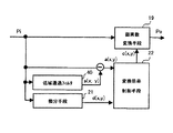
図1は、本発明の一実施形態による画像処理装置の動作を概略的に説明するための説明図である。原画像をn倍の変換倍率で拡大する場合の動作について示している。図1においてp(x)は原画像の画像レベルを表す画像データ、a(x)は画像データp(x)の高域画像データ、d(x)は画像データp(x)の一次微分データである。c(x)は、高域画像データa(x)、および一次微分データd(x)に基づいて以下の式により算出される変換倍率である。
【0011】
【数2】
![]()
式(2)において、nは画像全体としての設定倍率であり、kは輪郭部の鮮鋭度を制御する所定の係数である。ここで、設定倍率nは画像全体としての変換倍率である。図1に示すように変換倍率c(x)は、画像レベルが変化する輪郭部の前部(図1においてbにより示す区間)では設定倍率nに比して高く、輪郭部の後部(図1においてcにより示す区間)では設定倍率nに比して低くなる。ただし、変換倍率c(x)の平均値はnとなる。Poは変換倍率c(x)に基づいて拡大された画像データである。画像データPoにおいて、b’により示す区間は上述した輪郭部の前部(区間b)に対応しており、c’により示す区間は上述した輪郭部の後部(区間c)に対応している。このように、輪郭部における変換倍率を部分的に変化させることにより、輪郭部の鮮鋭度が保存された拡大画像を得ることができる。さらに、式(2)において、係数kの値を大きくすることにより輪郭部の前部(区間b)および後部(区間c)における変換倍率c(x)を所望の大きさとし、画像の鮮鋭度を調整することができる。
【0013】
以上のように、画像の拡大処理を行なう際、原画像の高域画像データ、および一次微分データを検出することにより得られる画像レベルの変化に関する特徴量に基づいて、輪郭部における変換倍率を部分的に変化させることにより、輪郭部の鮮鋭度を保存し、また調整することができる。
【0014】
図1に基づいて説明したように、輪郭部における変換倍率を部分的に変化させるには、変換倍率が高い部分では補間密度を相対的に高くし、変換倍率が低い部分では補間密度を相対的に低くすることにより補間画素データを算出すればよい。
【0015】
図2は、輪郭部における補間画素データの生成方法について説明するための説明図である。同図において、p1,p2,p3は輪郭部における原画像の画素データを表し、q’1〜q’7は変換倍率に応じて設定される仮の補間点(以下、単に補間点と称す)を表している。同図は、設定倍率nを3倍とした場合の画素数の変換動作を示しており、この場合、原画像の各画素データの間隔を1とすると、設定倍率nの逆数、すなわち1/3の間隔で画像データp(x)が補間されるように補間点q’1〜q’7が設定される。ここで、変換倍率c(x)が相対的に高い輪郭部の前部では補間密度が高く、変換倍率が相対的に低い輪郭部の後部では補間密度が低くなるように仮想的な補間点q’1〜q’7に対応する実際の補間点を設定する。q1〜q7は、補間点q’1〜q’7に対応する実際の補間点としての画素データ生成点である。画素データ生成点q1〜q7の位置は、各補間点q’1〜q’7における変換倍率c(q’1)〜c(q’7)の逆数に基づいて算出される。つまり、q1とq2との距離はp1とp2との距離を1とした場合、q’2における変換倍率c(q’2)の逆数により求められ、同様にq2とq3との距離はq’3における変換倍率c(q’3)の逆数により求められる。従って、各補間点q’nにおける変換倍率c(q’n)の逆数を累積加算することで各画素データ生成点qnの位置が設定される。尚、画像レベルの変化が生じない区間a(輪郭部以外の領域)においては、補間点q’および画素データ生成点qの位置は同一となる。
【0016】
上記のように設定された画素データ生成点q1〜q7における補間画素データpo’1〜po’7を算出し、これらの補間画素データpo’1〜po’7を原画像に対応する新たな画像の画素データpo1〜po7とすることにより輪郭部の鮮鋭度を制御することができる。ここで、補間画素データp’onは、図2に示す補間係数F(x)により式(1)に基づいて算出することができる。
【0017】
上記の動作を画像の水平方向、および垂直方向について行なうことにより、輪郭部の鮮鋭度を保存し、また適切に調整された状態で画素数の変換(画像の拡大・縮小、走査線補間等)を行なうことができる。
尚、上記の説明では、画像を拡大する場合について説明したが、画像を縮小する場合においても適用することができる。この場合、輪郭部の画像が欠落することなく画像を縮小することができる。
【0018】
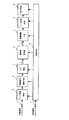
以下、上記動作を実現する画像処理装置の構成を図面に基づいて説明する。図3は、本実施の形態による画像処理装置の構成を示すブロック図である。垂直画素数変換部61は、原画像を表す画像データPiの垂直方向の画素数を変換し、画像データPvを出力する。水平画素数変換部62は、画像データPvの水平方向の画素数を変換し、画像データPoを出力する。
【0019】
垂直高域通過フィルタ12は、画像データPiの垂直方向における高域画像データVa(y)を出力する。また、垂直微分手段13は画像データPiの垂直方向における一次微分データVd(y)を出力する。垂直変換倍率制御手段14は、画像データPiの垂直方向の高域画像データVa(y)、および一次微分結果Vd(y)に基づいて、垂直変換倍率Vc(y)を算出し、垂直画素数変換手段11に出力する。垂直変換倍率Vc(y)は、式(2)において、a(y)およびd(y)をそれぞれVa(y)およびVd(y)に置き換えることにより、以下の式により表される。
【0020】
【数3】
垂直画素数変換手段11は、式(3)により算出された垂直変換倍率Vc(y)に基づいて、図2に示す動作により垂直方向の補間画素データpo’mを算出し、垂直方向の画素数が変換された画像データPvを水平画素数変換部62に出力する。
【0022】
水平高域通過フィルタ16は、画像データPvの水平方向における高域画像データHa(x)を出力する。また、水平微分手段17は画像データPvの水平方向における一次微分データHd(x)を出力する。水平変換倍率制御手段18は、画像データPvの水平方向の高域画像データHa(x)、および一次微分データHd(x)に基づいて、水平変換倍率Hc(x)を算出し、水平画素数変換手段15に出力する。水平変換倍率Hc(x)は、式(2)において、a(x)およびd(x)をそれぞれHa(x)およびHd(x)に置き換えることにより、以下の式により表される。
【0023】
【数4】
水平画素数変換手段15は、式(4)により算出された水平変換倍率Hc(x)に基づいて、図2に示す動作により補間画素データpo’nを算出し、画像データPoを出力する。
【0025】
垂直画素数変換部61、および水平画素数変換部62の基本的な動作は同様であり、水平画素数変換部62を垂直画素数変換部61の前段に設けても同様の効果を奏する。
尚、設定倍率nを1に設定することにより、輪郭強調のみを行なうことができる。また、設定倍率nを垂直方向と、水平方向とで異なる値に設定してもよい。例えば、垂直方向の設定倍率nを2とし、水平方向の設定倍率nを1とすることで、インタレース画像からノンインタレース画像への変換(走査線補間)を行なうことができる。さらに、式(3)、(4)により算出される垂直変換倍率Vc(x)、および水平変換倍率Hc(x)の係数kを独立に設定することで、垂直方向における輪郭部の鮮鋭度、および水平方向にける輪郭部の鮮鋭度を独立に制御することができる。
【0026】
また、垂直高域通過フィルタ12、および水平高域通過フィルタ16の代わりに、図4に示すように垂直低域通過フィルタ42、および水平低域通過フィルタ46を用いて垂直方向、および水平方向の高域画像データを出力するよう構成してもよい。つまり、垂直低域通過フィルタ42により出力される低域画像データVs(y)と、画像データPiとの差分により垂直方向における高域画像データVa(y)を出力し、水平低域通過フィルタ46により出力される低域画像データHs(x)と、画像データPvとの差分により水平方向における高域画像データHa(x)を出力するよう構成してもよい。
【0027】
実施の形態2.
実施の形態1による画像処理装置(図3に示す)において、垂直高域通過フィルタ12、水平高域通過フィルタ15を特定の帯域成分を出力する帯域フィルタ(バンドパスフィルタ)によって構成してもよい。実施の形態2による画像処理装置は、画像レベルの変化に関する特徴量を、画像データの輪郭部を形成する特定の帯域成分に基づいて算出するものである。
【0028】
図5は、本実施の形態による画素数変換器6の構成を示す図である。同図において、120は画像データPiの垂直方向における特定の帯域成分を出力する垂直帯域フィルタである。垂直帯域フィルタ120は、第1の低域通過フィルタ121の出力Vs1(y)と、これと遮断周波数が異なる第2の低域通過フィルタ122の出力Vs2(y)との差分を算出するように構成されている。160は画像データPvの水平方向における特定の帯域成分を出力する水平帯域フィルタである。水平帯域フィルタ160は、第1の低域通過フィルタ161の出力Hs1(x)と、これと遮断周波数が異なる第2の低域通過フィルタ162の出力Hs2(x)との差分を算出するように構成されている。
【0029】
図5に示す画像処理装置において、垂直画素数変換部61、および水平画素数変換部62の動作は同様であるので、ここでは水平画素数変換部62の動作について説明する。図6は、水平画素数変換部62の動作を説明するための説明図である。図6においてp(x)は画像データPvの水平方向における画像レベルを示す画像データ、Hs1(x)は第1の低域通過フィルタ161の出力、Hs2は第2の低域通過フィルタ162の出力、Hs1(x)−Hs2(x)は水平帯域フィルタ160の出力である。Hd(x)は画像データp(x)の一次微分データ、Hc(x)は画像データp(x)をn倍に拡大する場合の変換倍率、poは変換倍率Hc(x)に基づいて拡大された画像データを示す。図6に示す水平変換倍率Hc(x)は、水平帯域フィルタ160、水平微分手段17の出力に基づいて以下の式により算出される。
【0030】
【数5】
式(5)において、nは設定倍率、kは所定の係数である。水平変換倍率制御手段18は、上式(5)により水平変換倍率Hc(x)を算出し、水平画素数変換手段15に出力する。水平画素数変換手段15は、水平変換倍率Hc(x)に基づいて、実施の形態1において述べた動作と同様に画素数の変換を行なう。同様の動作を垂直方向についても行ない、垂直方向の画素数を変換する。
図5に示す画像処理装置は、垂直方向の画素数変換を行なった後に水平方向の画素数を変換するよう構成されているが、水平方向の画素数変換を行なってから垂直方向の画素数変換を行なっても同様の効果が得られる。
【0032】
上記の構成により、原画像の特定の高域成分に基づいて変換倍率c(x)を設定することにより、輪郭部において特定の高域成分のみを強調することができる。
【0033】
実施の形態3.
実施の形態1、2では、垂直方向の画素数変換、および水平方向の画素数変換の動作を順次行なうよう構成したが、垂直方向の画素数変換と水平方向の画素数変換を同時に行なうようにしてもよい。本実施の形態による画像処理装置は、垂直方向と水平方向の画素数変換を同時に行う画像処理装置に関する。
【0034】
図7は、本実施の形態による画像処理装置の画素数変換器の構成を示す図である。高域通過フィルタ20は、原画像の2次元方向における高域画像データa(x,y)を算出する。具体的には、演算対象となる補間点q’nmの水平、垂直、および斜め方向に配列する画素データに基づいてフィルタ演算を行なう。ここで、補間点q’nmは、実施の形態1、2で述べた補間点qn’に相当するが、本実施の形態における補間点q’nmは垂直、および水平の2方向、すなわち2次元方向に存在する。一次微分手段21は、原画像の2次元方向における一次微分データd(x,y)を算出する。具体的には、演算対象となる補間点q’nmの水平、垂直、および斜め方向に配列する画素データに基づいて一次微分演算を行なう。
本実施の形態において、補間点q’nm、画素データ生成点q’nm、変換倍率c(x,y)、高域画像データa(x,y)、一次微分データd(d,y)は、実施の形態1、2における補間点q’n、画素データ生成点qn、変換倍率c(x)、高域画像データa(x)、一次微分データd(x)に相当する。
【0035】
変換倍率制御手段22は、原画像の二次元方向における高域画像データa(x,y)、および1次微分データd(x,y)に基づいて、以下の式により変換倍率c(x,y)を算出する。
【0036】
【数6】
ここで、変換倍率c(x,y)は2次元データにより表され、水平方向および垂直方向における変換倍率が同時に算出される。画素数変換手段19は、各補間点q’nmにおける変換倍率c(x,y)に基づいて、画素データ生成点qnmを算出する。図8に、2次元データとして表される補間点q’nm、および対応する画素データ生成点qnmの一例を示す。画素数変換手段19は画素データ生成点qnmに隣接する4点の画素データに基づいて補間演算を行なう。図9は、qnmに隣接する原画像の画素データp11,p12,p21,p22に基づいて補間画素データpo’nmを算出する場合の算出方法について説明するための説明図である。同図において、G(x)は、2次元方向の補間演算に用いる補間係数の特性であり、対角方向に向かい合う画素データの間の距離が1の場合について示している。補間画素データpo’nmは、各画素データ生成点qnmと、隣接する画素データp11,p12,p21,p22との距離をr11,r12,r21,r22とした場合、以下の式により算出することができる。
【0038】
【数7】
以上のように、2次元方向の演算により、画素データ生成点qnmに最も近い近い画素データのうち少なくとも4点の画素データに基づいて補間演算を行なうことで、より精度の高い補間演算を行なうことができる。
【0040】
尚、上記の構成は図4、5に示す画像処理装置にも適用することができる。すなわち、図4に示す画像処理装置に適用する場合は、図10に示すように、低域通過フィルタ40により出力される2次元方向における低域画像データs(x,y)と、画像データPiとの差分により高域画像データa(x,y)を出力する。また、図5に示す画像表示装置に適用する場合は、図11に示すように、第1の低域通過フィルタ31の出力s1(x,y)と、遮断周波数が異なる第2の低域通過フィルタ32の出力s2(x,y)との差分により原画像の2次元方向における特定の帯域成分を算出し、変換倍率制御手段22に出力するよう構成する。
【0041】
実施の形態4.
実施の形態4は、実施の形態1〜3による画像処理装置の動作をソフトウェア制御により行なう場合の画像処理方法に関する。図12は本実施の形態による画像処理方法を示すフローチャートである。同図に示すフローチャートは、汎用コンピュータや、画像処理装置に内蔵されたマイクロコンピュータに以下において説明する画像処理を実行させるプログラムとして適用してもよい。同図に示すフローチャートは、垂直方向の画素数変換、および水平方向の画素数変換を順次行なう場合の画像処理方法について示している。
【0042】
St1において、垂直方向の画素数変換に必要な画素データが原画像の画像データPi(図3参照)から抽出される。ここでは、原画像を垂直方向に補間する各補間点q’mにおける高域画像データVa(y)、および一次微分データVd(y)の算出に必用な画素データが抽出される。具体的には、演算の対象となる補間点q’mに対し、垂直方向に隣接する画素データが抽出される。次に、St1において抽出された画素データに基づいて、補間点q’mにおける垂直方向の高域画像データVa(q’m)、および一次微分データVd(q’m)が算出される(St2)。
【0043】
次に、St2において算出された補間点q’mにおける画像データPiの高域画像データVa(q’m)、および一次微分データVd(q’m)により、式(3)に基づいて、補間点q’mにおける変換倍率Vc(q’m)が算出される(St3)。次に、St3において算出された変換倍率Vc(q’m)に基づいて、画素データ生成点qmを算出して設定し、この画素データ生成点qmにおいて補間演算を行なう。そして、この演算により得られた補間画素データpo’mを、原画像に対応する新たな画像を構成する画素データpomとして保存する(St4)。上記St1〜St4の動作を水平方向に行なった後(St5)、次のラインに配列する補間点q’m+1についてSt1〜St4の動作を行なう(St6)。St5において、画像の左側からSt1〜St4の演算を行なう場合は画像の右端が画像の最終端となる。上記の動作を最終ラインに達するまで行なうことにより垂直方向の画素数が変換された画像データPv(図3参照)が生成される。
【0044】
垂直方向の画素数が変換された後、St7において、水平方向の画素数変換に必要な画素データが画像データPvから抽出される。ここでは、原画像を水平方向に補間する各補間点q’nにおける高域画像データHa(x)、および一次微分データHd(x)の算出に必要な画素データが抽出される。具体的には、演算の対象となる補間点q’nに対し、水平方向に隣接する画素データが抽出される。次に、St8において抽出された画素データに基づいて、補間点q’nにおける水平方向の高域周波数成分Ha(q’n)、および一次微分値Hd(q’n)が算出される(St8)。
【0045】
次に、St8において算出された補間点q’nにおける画像データPiの高域画像データHa(q’n)、および一次微分データHd(q’n)により、式(4)に基づいて、補間点q’nにおける変換倍率Hc(q’n)が算出される(St9)。次に、St9において算出された変換倍率Hc(q’n)に基づいて、画素データ生成点qnを算出して設定し、この画素データ生成点qnにおいて補間演算を行なう。そして、この演算により得られた補間画素データp’onを、原画像に対応する新たな画像を構成する画素データponとして保存する(St10)。上記St7〜St10の動作を水平方向に行なった後(St11)、次のラインに配列する補間点q’n+1についてSt7〜St10の動作を行なう(St12)。St11において、画像の左側からSt7〜St10の演算を行なう場合は画像の右端が画像の最終端となる。上記の動作を最終ラインに達するまで行なうことにより垂直方向および水平方向の画素数が変換された画像データPoが生成される。
【0046】
なお、上記動作の説明では、垂直方向の画素数を変換した後に水平方向の画素数を変換する場合について示したが、水平方向の画素数を変換した後に垂直方向の画素数を変換してもよい。また、上記の画像処理方法は、水平方向と垂直方向の画素数を同時に変換する場合についても適用することができる。
【0047】
また、上記動作の説明では、垂直および水平の画素数を変換する際、補間画素データを画像の左から右、上から下の順番で演算する場合について示したが、この限りではなく、任意の方向から演算しても同様の結果を得ることができる。
【0048】
尚、実施の形態2に示したように複数の帯域フィルタを用いて、特定の高域画像データを出力する場合は、St2、およびSt8において、2種類のフィルタ演算を行ない、両者の演算結果の差を出力すればよい。
【0049】
実施の形態5.
本実施の形態は、実施の形態1〜4に示す画像処理装置を用いた画像表示装置に関するものである。フォーマットの異なる画像信号を表示するには、画像表示装置において入力画像を表示可能な画素数に変換する必要がある。例えば、640ドット×480ラインの画像を、1024ドット×728ラインの表示装置(例えば、液晶パネル)に表示するには、表示装置において画素数の変換を行なう。入力画像の画素数に対し、表示装置の表示画素数が大きい場合、従来の技術において述べたように、画像の拡大処理に伴い輪郭部の鮮鋭度が劣化する問題が生じる。こうした問題は、画像表示装置に実施の形態1〜4に示す画像処理装置を設けるか、あるいはこうした画像処理装置の出力を画像表示装置に与えることにより解決することができる。
【0050】
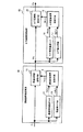
図13に、本実施の形態による画像処理装置の構成を示す。同図において、6は実施の形態1〜4に示す画像処理装置により構成される画素数変換器であり、内部構成は、図3、4、5、7、10または11により示される。デジタル画像データは入力端子1を介して画像信号調整手段4に入力され、対応する同期信号は、入力端子2を介して制御手段31に入力される。制御手段31は、同期信号に基づいて制御信号を生成する。画像信号調整手段4は、画像データを後段の画素数変換器6での処理に適した形式に変換する(例えば、画像データが符号化されたデジタル画像データの場合は復号化処理を行なう。)。画像信号調整手段4により出力された画像データは、メモリ手段5に一時的に記憶される。ここで、メモリ手段5は、画素数変換器6での処理に必要な(少なくとも2ライン以上)画像データを記憶する。
【0051】
画素数変換器6は、メモリ手段5により出力される画像データPiに対し、実施の形態1〜4において述べた動作により画素数の変換処理を行なう。画素数変換器6により出力された画像データPoは画像調整手段7に入力される。画像調整手段7は、画像データPoに対してコントラスト、彩度の調整や階調制御などの画像処理を行ない、表示装置30に出力する。表示手段30は、制御手段31の制御信号に基づいて、画像データPoに対応する画像を表示する。
【0052】
図14は、アナログ形式の画像信号を表示する場合の画像表示装置の構成例を示す図である。A/D変換手段3は、アナログ画像信号を所定のサンプリング周期で標本化し、画像信号調整手段4に出力する。画像信号調整手段4は、入力された画像データを後段の画素数変換器6での処理に適した形式に変換する。例えば、画素数変換器6において画像データPiをRGBの3原色画像データとして処理する場合は、入力画像信号をRGBの3原色画像データに変換する。また、画素数変換器6において画像データPiをYC信号として処理する場合は、入力画像信号をYC信号に変換する。画像信号調整手段4で所定の形式に変換された画像データは、メモリ手段5に一時的に記憶される。
【0053】
メモリ手段5から読み出された画像データPiは、画素数変換器6に入力される。画素数変換器6により出力された画像データPoは、画像調整手段7に入力される。画像調整手段7は、画像データPoに対してコントラスト、彩度の調整や階調制御などの画像処理を行ない、D/A変換手段8に出力する。D/A変換器8は、アナログ形式に変換した画像信号を表示手段9に出力する。表示手段9は、制御手段10の制御信号に基づいて、画像データPoに対応する画像を表示する。
【0054】
【発明の効果】
本発明に係る画像処理装置および画像処理方法によれば、画像データの変化に応じて補間画素の密度を調整する倍率変化量を求め、当該倍率変化量を用いて補間画素の画素データを算出するので、輪郭部における鮮鋭度を損なうことなく画像の拡大処理を行うことができる。
また、入力画像の輪郭部を補正する補間画素の密度を画像データの変化に応じて調整するための倍率変化量を求め、当該倍率変化量を用いて補間画素の画素データを算出するので、輪郭部の鮮鋭度を向上させ、より鮮明な画像を得ることができる。
【図面の簡単な説明】
【図1】 実施の形態1による画像処理動作を説明するための説明図である。
【図2】 実施の形態1による画像処理動作を説明するための説明図である。
【図3】 実施の形態1による画像処理装置の構成を示す図である。
【図4】 実施の形態1による画像処理装置の構成を示す図である。
【図5】 実施の形態2による画像処理装置の構成を示す図である。
【図6】 実施の形態2による画像処理動作を説明するための説明図である。
【図7】 実施の形態3による画像処理装置の構成を示す図である。
【図8】 実施の形態3による画像処理装置の動作を説明するための説明図である。
【図9】 実施の形態3による画像処理装置の動作を説明するための説明図である。
【図10】 実施の形態3による画像処理装置の構成を示す図である。
【図11】 実施の形態3による画像処理装置の構成を示す図である。
【図12】 実施の形態4による画像処理方法を示すフローチャートである。
【図13】 実施の形態5による画像表示装置の構成を示す図である。
【図14】 実施の形態5による画像表示装置の構成を示す図である。
【図15】 従来の画素数の変換動作について説明するための説明図である。
【図16】 従来の画素数の変換動作について説明するための説明図である。
【図17】 従来の画像処理における問題点を説明するための説明図である。
【符号の説明】
6 画素数変換器、9,30 表示手段、10,31 制御手段、11 垂直画素数変換手段、12 垂直高域通過フィルタ、13 垂直微分手段、14 垂直変換倍率制御手段、15 水平画素数変換手段、16 帯域制限手段、17 水平微分手段、18 水平変換倍率制御手段、19 画素数変換手段、20 高域通過フィルタ、21 微分手段、22 変換倍率制御手段、31,121,161 第1の低域通過フィルタ、32,122,162 第2の低域通過フィルタ、40 低域通過フィルタ、42 垂直低域通過フィルタ、46 水平低域通過フィルタ。[0001]
BACKGROUND OF THE INVENTION
The present invention relates to an image processing apparatus including an image enlargement or reduction process, and an image processing method.
[0002]
[Prior art]
When the image is enlarged / reduced to an arbitrary magnification, a predetermined interpolation operation is performed on the pixel data of the original image to calculate the number of interpolation pixel data different from the number of pixels of the original image. For example, when the display format is 1024 pixels × 728 lines and the input image (original image) has an image format of 640 pixels × 480 lines, to display the input image on the entire display, an interpolation operation is performed. It is necessary to calculate the number of interpolation pixel data corresponding to the number of display pixels (the conversion magnification in the enlargement process in this case is 1.6).
[0003]
FIG. 15 is an explanatory diagram for describing a method of calculating interpolation pixel data when an image is enlarged. In the figure, Pn and Pn + 1 are part of pixel data constituting the original image, qn (indicated by x in the figure) is an interpolation point, and pon is interpolation pixel data calculated at the interpolation point qn. FIG. 13 shows a case where interpolation pixel data is calculated by linear interpolation, and F (x) is a function indicating the characteristics of the interpolation coefficient used for the interpolation calculation. Here, for simplicity, when the interval between the pixels of the original image is 1, and the distance between the interpolation point qn and the pixel data Pn is r, the interpolation pixel data Pon is calculated by the following equation.
[0004]
[Expression 1]
FIG. 16 is an explanatory diagram for explaining a method of calculating interpolation pixel data when an image is enlarged by the interpolation calculation described with reference to FIG. In the figure, p11, p12, and p13 are pixel data of the original image, q11 to q17 (indicated by x in the figure) are interpolation points for calculating interpolation pixel data, and po11 to po17 are calculated at interpolation points q11 to q17. Interpolation pixel data. This figure shows a case where the original image is enlarged three times, and the interpolation points q11 to q17 are set at an interval of 1/3, where 1 is the interval between pixels of the original image. As shown in the figure, an interpolation point qn is set according to the conversion magnification or the number of conversion pixels, and an enlarged image or reduced image is obtained by performing the interpolation calculation shown in Expression (1) for all the set interpolation points qn. Generate an image.
[0006]
[Problems to be solved by the invention]
Problems in the case of enlarging an image by conventional interpolation calculation will be described with reference to FIG. FIG. 17 shows an output image obtained by enlarging an input image by a conventional interpolation calculation. As shown in the figure, when the image is enlarged by the conventional interpolation calculation, there is a problem that the sharpness of the contour portion J ′ of the output image corresponding to the contour portion J of the input image is lowered. Further, according to contour enhancement using a contour signal that has been generally used in the past, there is a problem that image quality deterioration occurs due to overshoot or undershoot around the contour portion.
[0007]
The present invention has been made in view of the above problems, and can appropriately adjust the sharpness of the contour portion of the image, and can enlarge and reduce the image without causing image quality deterioration in the contour portion. An object of the present invention is to realize a simple image processing apparatus.
[0008]
[Means for Solving the Problems]
An image processing apparatus according to the present invention is an image processing apparatus that converts the number of pixels of the input image by performing an interpolation calculation process on image data representing the input image,
Filter means for detecting a predetermined frequency component of the image data;
Differentiating means for detecting a first derivative of the image data;
A value obtained by multiplying the predetermined frequency component by the first derivative is used to obtain an adjustment amount for adjusting the density of interpolation pixels for interpolating the input image in accordance with a change in the image data, and the adjustment amount is used. Conversion magnification control means for obtaining the conversion magnification of each of the interpolation pixels,
Interpolation operation means for obtaining an interpolation position of each of the interpolation pixels based on the conversion magnification and calculating pixel data of the interpolation pixels by interpolation calculation at the interpolation position is provided.
[0009]
An image processing apparatus according to the present invention is an image processing apparatus that corrects the contour of an input image and outputs the corrected image.
Above pictureOf image dataFilter means for detecting a predetermined frequency component;
Differentiating means for detecting a first derivative of the image data;
A value obtained by multiplying the predetermined frequency component by the first derivative is used to obtain an adjustment amount for adjusting the density of interpolation pixels for correcting the contour portion of the input image according to the change in the contour portion of the input image. Conversion magnification control means for obtaining the conversion magnification of each of the interpolation pixels using the adjustment amount;
Interpolation operation means for obtaining an interpolation position of each of the interpolation pixels based on the conversion magnification and calculating pixel data of the interpolation pixels by interpolation calculation at the interpolation position is provided.
[0010]
DETAILED DESCRIPTION OF THE INVENTION
FIG. 1 is an explanatory diagram for schematically explaining the operation of an image processing apparatus according to an embodiment of the present invention. The operation in the case of enlarging an original image at a conversion magnification of n times is shown. In FIG. 1, p (x) is image data representing the image level of the original image, a (x) is high-frequency image data of the image data p (x), and d (x) is primary differential data of the image data p (x). It is. c (x) is a conversion magnification calculated by the following equation based on the high-frequency image data a (x) and the primary differential data d (x).
[0011]
[Expression 2]
![]()
In Equation (2), n is a set magnification for the entire image, and k is a predetermined coefficient for controlling the sharpness of the contour portion. Here, the set magnification n is a conversion magnification of the entire image. As shown in FIG. 1, the conversion magnification c (x) is higher than the set magnification n in the front part of the contour portion where the image level changes (section indicated by b in FIG. 1), and the rear part of the contour portion (FIG. 1). In the interval indicated by c in FIG. However, the average value of the conversion magnification c (x) is n. Po is image data enlarged based on the conversion magnification c (x). In the image data Po, the section indicated by b 'corresponds to the front part (section b) of the above-described contour part, and the section indicated by c' corresponds to the rear part (section c) of the above-described contour part. Thus, by partially changing the conversion magnification in the contour portion, an enlarged image in which the sharpness of the contour portion is preserved can be obtained. Further, in equation (2), by increasing the value of the coefficient k, the conversion magnification c (x) in the front part (section b) and rear part (section c) of the contour is set to a desired size, and the sharpness of the image is set. Can be adjusted.
[0013]
As described above, when the image enlargement process is performed, the conversion magnification in the contour portion is partially calculated based on the feature amount relating to the change in the image level obtained by detecting the high-frequency image data of the original image and the primary differential data. Therefore, the sharpness of the contour portion can be preserved and adjusted.
[0014]
As described with reference to FIG. 1, in order to partially change the conversion magnification in the contour portion, the interpolation density is relatively high in the portion where the conversion magnification is high, and the interpolation density is relatively set in the portion where the conversion magnification is low. The interpolated pixel data may be calculated by lowering the value.
[0015]
FIG. 2 is an explanatory diagram for explaining a method of generating interpolation pixel data in the contour portion. In the figure, p1, p2, and p3 represent pixel data of the original image in the outline, and q′1 to q′7 are temporary interpolation points set according to the conversion magnification (hereinafter simply referred to as interpolation points). Represents. This figure shows the conversion operation of the number of pixels when the set magnification n is set to 3. In this case, if the interval between the pixel data of the original image is 1, the reciprocal of the set magnification n, that is, 1/3. Interpolation points q′1 to q′7 are set so that the image data p (x) is interpolated at intervals of. Here, the virtual interpolation point q is such that the interpolation density is high at the front part of the contour part where the conversion magnification c (x) is relatively high and the interpolation density is low at the rear part of the contour part where the conversion magnification is relatively low. Set actual interpolation points corresponding to '1 to q'7. q1 to q7 are pixel data generation points as actual interpolation points corresponding to the interpolation points q'1 to q'7. The positions of the pixel data generation points q1 to q7 are calculated based on the reciprocals of the conversion magnifications c (q'1) to c (q'7) at the respective interpolation points q'1 to q'7. That is, the distance between q1 and q2 is obtained by the reciprocal of the conversion magnification c (q′2) at q′2 when the distance between p1 and p2 is 1, and similarly, the distance between q2 and q3 is q ′. 3 is obtained by the reciprocal of the conversion magnification c (q′3) in FIG. Accordingly, the position of each pixel data generation point qn is set by cumulatively adding the reciprocal of the conversion magnification c (q'n) at each interpolation point q'n. It should be noted that the position of the interpolation point q 'and the pixel data generation point q are the same in the section a (region other than the contour portion) where the image level does not change.
[0016]
Interpolated pixel data po′1 to po′7 at the pixel data generation points q1 to q7 set as described above are calculated, and these interpolated pixel data po′1 to po′7 are new images corresponding to the original image. By using the pixel data po1 to po7, the sharpness of the contour can be controlled. Here, the interpolated pixel data p'on can be calculated based on the equation (1) using the interpolation coefficient F (x) shown in FIG.
[0017]
By performing the above operation in the horizontal and vertical directions of the image, the sharpness of the outline is preserved, and the number of pixels is converted in an appropriately adjusted state (image enlargement / reduction, scanning line interpolation, etc.) Can be performed.
In the above description, the case of enlarging an image has been described. However, the present invention can also be applied to the case of reducing an image. In this case, the image can be reduced without missing the image of the contour portion.
[0018]
Hereinafter, the configuration of an image processing apparatus that realizes the above-described operation will be described with reference to the drawings. FIG. 3 is a block diagram showing the configuration of the image processing apparatus according to this embodiment. The vertical
[0019]
The vertical high-
[0020]
[Equation 3]
The vertical pixel number conversion means 11 calculates the vertical interpolation pixel data po′m by the operation shown in FIG. 2 based on the vertical conversion magnification Vc (y) calculated by the equation (3), and the vertical pixel The image data Pv whose number has been converted is output to the horizontal pixel
[0022]
The horizontal high-
[0023]
[Expression 4]
The horizontal pixel
[0025]
The basic operations of the vertical pixel
It should be noted that by setting the set magnification n to 1, only contour enhancement can be performed. Further, the set magnification n may be set to a different value between the vertical direction and the horizontal direction. For example, when the set magnification n in the vertical direction is 2 and the set magnification n in the horizontal direction is 1, conversion from an interlaced image to a non-interlaced image (scanning line interpolation) can be performed. Further, by independently setting the coefficient k of the vertical conversion magnification Vc (x) and the horizontal conversion magnification Hc (x) calculated by the equations (3) and (4), the sharpness of the contour portion in the vertical direction, And the sharpness of the contour in the horizontal direction can be controlled independently.
[0026]
Further, instead of the vertical high-
[0027]
In the image processing apparatus (shown in FIG. 3) according to the first embodiment, the vertical high-
[0028]
FIG. 5 is a diagram showing a configuration of the pixel number converter 6 according to the present embodiment. In the figure,
[0029]
In the image processing apparatus shown in FIG. 5, the operations of the vertical pixel
[0030]
[Equation 5]
In equation (5), n is a set magnification and k is a predetermined coefficient. The horizontal conversion magnification control means 18 calculates the horizontal conversion magnification Hc (x) by the above equation (5) and outputs it to the horizontal pixel number conversion means 15. The horizontal pixel number conversion means 15 converts the number of pixels based on the horizontal conversion magnification Hc (x) in the same manner as the operation described in the first embodiment. A similar operation is performed in the vertical direction to convert the number of pixels in the vertical direction.
The image processing apparatus shown in FIG. 5 is configured to convert the number of pixels in the horizontal direction after converting the number of pixels in the vertical direction, but after converting the number of pixels in the horizontal direction, the number of pixels in the vertical direction is converted. The same effect can be obtained by performing the above.
[0032]
With the above configuration, by setting the conversion magnification c (x) based on the specific high frequency component of the original image, only the specific high frequency component can be emphasized in the contour portion.
[0033]
Embodiment 3 FIG.
In the first and second embodiments, the vertical pixel number conversion and the horizontal pixel number conversion are sequentially performed. However, the vertical pixel number conversion and the horizontal pixel number conversion are performed simultaneously. May be. The image processing apparatus according to the present embodiment relates to an image processing apparatus that simultaneously converts the number of pixels in the vertical direction and the horizontal direction.
[0034]
FIG. 7 is a diagram showing the configuration of the pixel number converter of the image processing apparatus according to this embodiment. The high-
In the present embodiment, the interpolation point q′nm, the pixel data generation point q′nm, the conversion magnification c (x, y), the high-frequency image data a (x, y), and the primary differential data d (d, y) are These correspond to the interpolation point q′n, the pixel data generation point qn, the conversion magnification c (x), the high-frequency image data a (x), and the primary differential data d (x) in the first and second embodiments.
[0035]
Based on the high-frequency image data a (x, y) and the primary differential data d (x, y) in the two-dimensional direction of the original image, the conversion magnification control means 22 converts the conversion magnification c (x, y) is calculated.
[0036]
[Formula 6]
Here, the conversion magnification c (x, y) is represented by two-dimensional data, and the conversion magnification in the horizontal direction and the vertical direction are calculated simultaneously. The pixel
[0038]
[Expression 7]
As described above, by performing the interpolation calculation based on the pixel data of at least four points among the pixel data closest to the pixel data generation point qnm by the calculation in the two-dimensional direction, the interpolation calculation with higher accuracy can be performed. Can do.
[0040]
The above configuration can also be applied to the image processing apparatus shown in FIGS. That is, when applied to the image processing apparatus shown in FIG. 4, as shown in FIG. 10, the low-pass image data s (x, y) in the two-dimensional direction output from the low-
[0041]
The fourth embodiment relates to an image processing method when the operation of the image processing apparatus according to the first to third embodiments is performed by software control. FIG. 12 is a flowchart showing an image processing method according to this embodiment. The flowchart shown in the figure may be applied as a program for causing a general-purpose computer or a microcomputer built in the image processing apparatus to execute image processing described below. The flowchart shown in the figure shows an image processing method in the case where the pixel number conversion in the vertical direction and the pixel number conversion in the horizontal direction are sequentially performed.
[0042]
In St1, pixel data necessary for the conversion of the number of pixels in the vertical direction is extracted from the image data Pi of the original image (see FIG. 3). Here, pixel data necessary for calculating the high-frequency image data Va (y) and primary differential data Vd (y) at each interpolation point q′m for interpolating the original image in the vertical direction is extracted. Specifically, pixel data adjacent in the vertical direction is extracted from the interpolation point q′m to be calculated. Next, based on the pixel data extracted in St1, vertical high-frequency image data Va (q'm) and primary differential data Vd (q'm) at the interpolation point q'm are calculated (St2). ).
[0043]
Next, interpolation is performed based on the equation (3) using the high-frequency image data Va (q′m) of the image data Pi at the interpolation point q′m calculated in St2 and the primary differential data Vd (q′m). A conversion magnification Vc (q′m) at the point q′m is calculated (St3). Next, the pixel data generation point qm is calculated and set based on the conversion magnification Vc (q′m) calculated in St3, and an interpolation operation is performed at the pixel data generation point qm. Then, the interpolated pixel data po′m obtained by this calculation is stored as pixel data pom constituting a new image corresponding to the original image (St4). After the operation of St1 to St4 is performed in the horizontal direction (St5), the operation of St1 to St4 is performed for the interpolation point q'm + 1 arranged in the next line (St6). In St5, when the calculation of St1 to St4 is performed from the left side of the image, the right end of the image is the final end of the image. By performing the above operation until the final line is reached, image data Pv (see FIG. 3) in which the number of pixels in the vertical direction is converted is generated.
[0044]
After the number of pixels in the vertical direction is converted, pixel data necessary for the conversion of the number of pixels in the horizontal direction is extracted from the image data Pv in St7. Here, pixel data necessary for calculating the high-frequency image data Ha (x) and the primary differential data Hd (x) at each interpolation point q′n for interpolating the original image in the horizontal direction is extracted. Specifically, pixel data adjacent in the horizontal direction is extracted for the interpolation point q′n to be calculated. Next, based on the pixel data extracted in St8, a horizontal high-frequency component Ha (q′n) and a primary differential value Hd (q′n) at the interpolation point q′n are calculated (St8). ).
[0045]
Next, interpolation is performed based on the equation (4) using the high-frequency image data Ha (q′n) of the image data Pi at the interpolation point q′n calculated in St8 and the primary differential data Hd (q′n). A conversion magnification Hc (q′n) at the point q′n is calculated (St9). Next, the pixel data generation point qn is calculated and set based on the conversion magnification Hc (q′n) calculated in St9, and an interpolation operation is performed at the pixel data generation point qn. Then, the interpolated pixel data p′on obtained by this calculation is stored as pixel data pon constituting a new image corresponding to the original image (St10). After performing the operations of St7 to St10 in the horizontal direction (St11), the operations of St7 to St10 are performed for the interpolation points q'n + 1 arranged in the next line (St12). In St11, when performing St7 to St10 from the left side of the image, the right end of the image is the final end of the image. By performing the above operation until the final line is reached, image data Po in which the number of pixels in the vertical and horizontal directions is converted is generated.
[0046]
In the above description of the operation, the case of converting the number of pixels in the horizontal direction after converting the number of pixels in the vertical direction has been described. However, the number of pixels in the vertical direction may be converted after converting the number of pixels in the horizontal direction. Good. The image processing method described above can also be applied to the case where the number of pixels in the horizontal direction and the vertical direction is converted simultaneously.
[0047]
In the description of the above operation, when the number of vertical and horizontal pixels is converted, the interpolation pixel data is calculated from the left to the right and the top to the bottom of the image. Similar results can be obtained by calculating from the direction.
[0048]
In the case where specific high-frequency image data is output using a plurality of band filters as shown in the second embodiment, two types of filter operations are performed in St2 and St8, and the results of both operations are calculated. What is necessary is just to output a difference.
[0049]
The present embodiment relates to an image display device using the image processing device shown in the first to fourth embodiments. In order to display image signals having different formats, it is necessary to convert the input image into the number of displayable pixels in the image display device. For example, in order to display an image of 640 dots × 480 lines on a display device (for example, a liquid crystal panel) of 1024 dots × 728 lines, the number of pixels is converted in the display device. When the number of display pixels of the display device is larger than the number of pixels of the input image, there is a problem that the sharpness of the contour portion deteriorates with the image enlargement process, as described in the related art. Such a problem can be solved by providing the image processing apparatus described in
[0050]
FIG. 13 shows the configuration of the image processing apparatus according to this embodiment. In the figure, reference numeral 6 denotes a pixel number converter configured by the image processing apparatus shown in the first to fourth embodiments, and the internal configuration is shown in FIG. Digital image data is input to the image signal adjustment means 4 via the
[0051]
The pixel number converter 6 performs pixel number conversion processing on the image data Pi output from the memory means 5 by the operation described in the first to fourth embodiments. The image data Po output by the pixel number converter 6 is input to the image adjusting means 7. The
[0052]
FIG. 14 is a diagram illustrating a configuration example of an image display device in the case of displaying an analog image signal. The A / D conversion means 3 samples the analog image signal at a predetermined sampling period and outputs it to the image signal adjustment means 4. The image signal adjusting means 4 converts the input image data into a format suitable for processing by the pixel number converter 6 at the subsequent stage. For example, when the pixel number converter 6 processes the image data Pi as RGB primary color image data, the input image signal is converted into RGB primary color image data. Further, when the image data Pi is processed as a YC signal in the pixel number converter 6, the input image signal is converted into a YC signal. The image data converted into a predetermined format by the image
[0053]
The image data Pi read from the memory means 5 is input to the pixel number converter 6. The image data Po output by the pixel number converter 6 is input to the image adjusting means 7. The
[0054]
【The invention's effect】
Image processing apparatus according to the present inventionAccording to the image processing method, the amount of change in magnification for adjusting the density of the interpolation pixel in accordance with the change in the image data is obtained, and the pixel data of the interpolation pixel is calculated using the amount of change in magnification. Enlargement without damaging the imagebe able to.
Further, since the magnification change amount for adjusting the density of the interpolation pixel for correcting the contour portion of the input image according to the change of the image data is obtained and the pixel data of the interpolation pixel is calculated using the magnification change amount, the contour The sharpness of the part can be improved and a clearer image can be obtained.
[Brief description of the drawings]
FIG. 1 is an explanatory diagram for explaining an image processing operation according to a first embodiment;
FIG. 2 is an explanatory diagram for explaining an image processing operation according to the first embodiment;
3 is a diagram showing a configuration of an image processing apparatus according to
4 is a diagram showing a configuration of an image processing apparatus according to
FIG. 5 is a diagram showing a configuration of an image processing apparatus according to a second embodiment.
FIG. 6 is an explanatory diagram for explaining an image processing operation according to the second embodiment.
7 is a diagram showing a configuration of an image processing apparatus according to Embodiment 3. FIG.
FIG. 8 is an explanatory diagram for explaining the operation of the image processing apparatus according to the third embodiment.
FIG. 9 is an explanatory diagram for explaining the operation of the image processing apparatus according to the third embodiment;
FIG. 10 is a diagram illustrating a configuration of an image processing apparatus according to a third embodiment.
FIG. 11 is a diagram illustrating a configuration of an image processing apparatus according to a third embodiment.
FIG. 12 is a flowchart illustrating an image processing method according to the fourth embodiment.
FIG. 13 is a diagram showing a configuration of an image display device according to a fifth embodiment.
FIG. 14 is a diagram illustrating a configuration of an image display device according to a fifth embodiment.
FIG. 15 is an explanatory diagram for explaining a conventional pixel number conversion operation;
FIG. 16 is an explanatory diagram for explaining a conventional pixel number conversion operation;
FIG. 17 is an explanatory diagram for explaining a problem in conventional image processing.
[Explanation of symbols]
6 pixel number converter, 9, 30 display means, 10, 31 control means, 11 vertical pixel number conversion means, 12 vertical high-pass filter, 13 vertical differentiation means, 14 vertical conversion magnification control means, 15 horizontal pixel number conversion means , 16 Band limiting means, 17 Horizontal differentiation means, 18 Horizontal conversion magnification control means, 19 Pixel number conversion means, 20 High-pass filter, 21 Differentiation means, 22 Conversion magnification control means, 31, 121, 161 First low frequency Pass filter, 32, 122, 162 Second low pass filter, 40 Low pass filter, 42 Vertical low pass filter, 46 Horizontal low pass filter.
Claims (10)
上記画像データの所定の周波数成分を検出するフィルタ手段と、
上記画像データの一次微分を検出する微分手段と、
上記所定の周波数成分に上記一次微分を乗じた値を用いて、上記入力画像を補間する補間画素の密度を上記画像データの変化に応じて調整するための調整量を求め、当該調整量を用いて上記補間画素の各々の変換倍率を求める変換倍率制御手段と、
上記変換倍率に基づいて上記補間画素の各々の補間位置を求め、当該補間位置における補間演算により上記補間画素の画素データを算出する補間演算手段とを備えたことを特徴とする画像処理装置。An image processing apparatus that converts the number of pixels of the input image by performing an interpolation calculation process on image data representing the input image,
Filter means for detecting a predetermined frequency component of the image data;
Differentiating means for detecting a first derivative of the image data;
A value obtained by multiplying the predetermined frequency component by the first derivative is used to obtain an adjustment amount for adjusting the density of interpolation pixels for interpolating the input image in accordance with a change in the image data, and the adjustment amount is used. Conversion magnification control means for obtaining the conversion magnification of each of the interpolation pixels,
An image processing apparatus comprising: an interpolation calculation unit that obtains an interpolation position of each of the interpolation pixels based on the conversion magnification and calculates pixel data of the interpolation pixel by an interpolation calculation at the interpolation position.
上記画像データの所定の周波数成分を検出するフィルタ手段と、
上記画像データの一次微分を検出する微分手段と、
上記所定の周波数成分に上記一次微分を乗じた値を用いて、上記入力画像の輪郭部を補正する補間画素の密度を上記入力画像の輪郭部の変化に応じて調整するための調整量を求め、当該調整量を用いて上記補間画素の各々の変換倍率を求める変換倍率制御手段と、
上記変換倍率に基づいて上記補間画素の各々の補間位置を求め、当該補間位置における補間演算により上記補間画素の画素データを算出する補間演算手段とを備えたことを特徴とする画像処理装置。An image processing apparatus for correcting and outputting an outline of an input image,
Filter means for detecting a predetermined frequency component of the picture image data,
Differentiating means for detecting a first derivative of the image data;
A value obtained by multiplying the predetermined frequency component by the first derivative is used to obtain an adjustment amount for adjusting the density of interpolation pixels for correcting the contour portion of the input image according to the change in the contour portion of the input image. Conversion magnification control means for obtaining the conversion magnification of each of the interpolation pixels using the adjustment amount;
An image processing apparatus comprising: an interpolation calculation unit that obtains an interpolation position of each of the interpolation pixels based on the conversion magnification and calculates pixel data of the interpolation pixel by an interpolation calculation at the interpolation position.
上記画像データの所定の周波数成分を検出する工程と、
上記画像データの一次微分を検出する工程と、
上記所定の周波数成分に上記入力画像の一次微分を乗じた値を用いて、上記入力画像を補間する補間画素の密度を上記画像データの変化に応じて調整するための調整量を求め、当該調整量を用いて上記補間画素の各々の変換倍率を求める工程と、
上記変換倍率に基づいて上記補間画素の各々の補間位置を求め、当該補間位置における補間演算により上記補間画素の画素データを算出する工程とを備えたことを特徴とする画像処理方法。An image processing method for converting the number of pixels of the input image by performing an interpolation calculation process on image data representing the input image,
Detecting a predetermined frequency component of the image data;
Detecting a first derivative of the image data;
A value obtained by multiplying the predetermined frequency component by the first derivative of the input image is used to obtain an adjustment amount for adjusting the density of interpolation pixels for interpolating the input image in accordance with the change in the image data. Determining the conversion magnification of each of the interpolated pixels using a quantity;
An image processing method comprising: calculating an interpolation position of each of the interpolation pixels based on the conversion magnification, and calculating pixel data of the interpolation pixel by an interpolation calculation at the interpolation position.
上記画像データの所定の周波数成分を検出する工程と、
上記画像データの一次微分を検出する工程と、
上記所定の周波数成分に上記一次微分を乗じた値を用いて、上記入力画像の輪郭部を補正する補間画素の密度を上記入力画像の輪郭部の変化に応じて調整するための調整量を求め、当該調整量を用いて上記補間画素の各々の変換倍率を求める工程と、
上記変換倍率に基づいて上記補間画素の各々の補間位置を求め、当該補間位置における補間演算により上記補間画素の画素データを算出する工程とを備えたことを特徴とする画像処理方法。An image processing method for correcting and outputting an outline of an input image,
A step of detecting a predetermined frequency component of the upper outs image data,
Detecting a first derivative of the image data;
A value obtained by multiplying the predetermined frequency component by the first derivative is used to obtain an adjustment amount for adjusting the density of interpolation pixels for correcting the contour portion of the input image according to the change in the contour portion of the input image. Determining the conversion magnification of each of the interpolation pixels using the adjustment amount;
An image processing method comprising: calculating an interpolation position of each of the interpolation pixels based on the conversion magnification, and calculating pixel data of the interpolation pixel by an interpolation calculation at the interpolation position.
Priority Applications (4)
| Application Number | Priority Date | Filing Date | Title |
|---|---|---|---|
| JP2001061436A JP3719389B2 (en) | 2001-03-06 | 2001-03-06 | Image processing apparatus, image display apparatus, and image processing method |
| US09/883,940 US6724398B2 (en) | 2000-06-20 | 2001-06-20 | Image processing method and apparatus, and image display method and apparatus, with variable interpolation spacing |
| US10/716,634 US7330199B2 (en) | 2000-06-20 | 2003-11-20 | Image processing method and apparatus, and image display method and apparatus, with variable interpolation spacing |
| US11/013,419 US7429994B2 (en) | 2000-06-20 | 2004-12-17 | Image processing method and apparatus, and image display method and apparatus for changing edge sharpness |
Applications Claiming Priority (1)
| Application Number | Priority Date | Filing Date | Title |
|---|---|---|---|
| JP2001061436A JP3719389B2 (en) | 2001-03-06 | 2001-03-06 | Image processing apparatus, image display apparatus, and image processing method |
Publications (3)
| Publication Number | Publication Date |
|---|---|
| JP2002262071A JP2002262071A (en) | 2002-09-13 |
| JP2002262071A5 JP2002262071A5 (en) | 2005-07-28 |
| JP3719389B2 true JP3719389B2 (en) | 2005-11-24 |
Family
ID=18920729
Family Applications (1)
| Application Number | Title | Priority Date | Filing Date |
|---|---|---|---|
| JP2001061436A Expired - Fee Related JP3719389B2 (en) | 2000-06-20 | 2001-03-06 | Image processing apparatus, image display apparatus, and image processing method |
Country Status (1)
| Country | Link |
|---|---|
| JP (1) | JP3719389B2 (en) |
Families Citing this family (2)
| Publication number | Priority date | Publication date | Assignee | Title |
|---|---|---|---|---|
| EP1580692A4 (en) * | 2002-12-20 | 2007-07-18 | Mitsubishi Electric Corp | Image processing device, image display device, image processing method, and image display method |
| JP3753731B1 (en) * | 2005-02-18 | 2006-03-08 | 三菱電機株式会社 | Image processing apparatus, image processing method, and image display apparatus |
-
2001
- 2001-03-06 JP JP2001061436A patent/JP3719389B2/en not_active Expired - Fee Related
Also Published As
| Publication number | Publication date |
|---|---|
| JP2002262071A (en) | 2002-09-13 |
Similar Documents
| Publication | Publication Date | Title |
|---|---|---|
| CN100484188C (en) | Resolution-converting apparatus and method | |
| EP1032196B1 (en) | Method and apparatus for reducing motion artifacts and noise in video image processing | |
| JP4534594B2 (en) | Image processing apparatus, image processing method, program for image processing method, and recording medium recording program for image processing method | |
| US7483040B2 (en) | Information processing apparatus, information processing method, recording medium, and program | |
| CN100463493C (en) | Method of converting resolution of video signals and apparatus using the same | |
| US7782401B1 (en) | Method and system for digital image scaling with sharpness enhancement and transient improvement | |
| US8189941B2 (en) | Image processing device, display device, image processing method, and program | |
| JP4214457B2 (en) | Image processing apparatus and method, recording medium, and program | |
| WO2006090515A1 (en) | Image processing device, image processing method, and image display device | |
| JP4518392B2 (en) | Method and apparatus for converting color images | |
| JP2004349979A (en) | Image processing apparatus, image processing method, and image projector | |
| US6961479B1 (en) | Image processing device, image processing method, image-processing program recorded medium | |
| US8345163B2 (en) | Image processing device and method and image display device | |
| JP3719389B2 (en) | Image processing apparatus, image display apparatus, and image processing method | |
| JP2005012561A (en) | Image processing apparatus, image processing method, and image projector | |
| US9401010B2 (en) | Enhancing perceived sharpness of images | |
| JP3695291B2 (en) | Image processing apparatus, image display apparatus, and image processing method | |
| WO2010046989A1 (en) | Frame rate converting device, image processing device, display, frame rate converting method, its program, and recording medium where the program is recorded | |
| JP3692942B2 (en) | Image processing apparatus, image display apparatus, and image processing method | |
| TWI413019B (en) | Image adjusting circuit and image adjusting method | |
| WO2006054201A1 (en) | Video data enhancement | |
| JP2007151094A (en) | Tone-conversion device for image, program, electronic camera, and tone-conversion method | |
| JP4689243B2 (en) | Image processing apparatus, image processing method, and digital camera | |
| JP2001331145A (en) | Device and method for converting image | |
| JP2008259242A (en) | Image processing apparatus, image processing method, recording medium, and program |
Legal Events
| Date | Code | Title | Description |
|---|---|---|---|
| RD01 | Notification of change of attorney |
Free format text: JAPANESE INTERMEDIATE CODE: A7421 Effective date: 20040708 |
|
| A521 | Request for written amendment filed |
Free format text: JAPANESE INTERMEDIATE CODE: A523 Effective date: 20041210 |
|
| A621 | Written request for application examination |
Free format text: JAPANESE INTERMEDIATE CODE: A621 Effective date: 20041210 |
|
| A131 | Notification of reasons for refusal |
Free format text: JAPANESE INTERMEDIATE CODE: A131 Effective date: 20050301 |
|
| A521 | Request for written amendment filed |
Free format text: JAPANESE INTERMEDIATE CODE: A523 Effective date: 20050425 |
|
| TRDD | Decision of grant or rejection written | ||
| A01 | Written decision to grant a patent or to grant a registration (utility model) |
Free format text: JAPANESE INTERMEDIATE CODE: A01 Effective date: 20050817 |
|
| A61 | First payment of annual fees (during grant procedure) |
Free format text: JAPANESE INTERMEDIATE CODE: A61 Effective date: 20050830 |
|
| FPAY | Renewal fee payment (event date is renewal date of database) |
Free format text: PAYMENT UNTIL: 20080916 Year of fee payment: 3 |
|
| FPAY | Renewal fee payment (event date is renewal date of database) |
Free format text: PAYMENT UNTIL: 20090916 Year of fee payment: 4 |
|
| FPAY | Renewal fee payment (event date is renewal date of database) |
Free format text: PAYMENT UNTIL: 20090916 Year of fee payment: 4 |
|
| FPAY | Renewal fee payment (event date is renewal date of database) |
Free format text: PAYMENT UNTIL: 20100916 Year of fee payment: 5 |
|
| FPAY | Renewal fee payment (event date is renewal date of database) |
Free format text: PAYMENT UNTIL: 20110916 Year of fee payment: 6 |
|
| LAPS | Cancellation because of no payment of annual fees |