JP3717885B2 - Projection display device - Google Patents
Projection display device Download PDFInfo
- Publication number
- JP3717885B2 JP3717885B2 JP2002361140A JP2002361140A JP3717885B2 JP 3717885 B2 JP3717885 B2 JP 3717885B2 JP 2002361140 A JP2002361140 A JP 2002361140A JP 2002361140 A JP2002361140 A JP 2002361140A JP 3717885 B2 JP3717885 B2 JP 3717885B2
- Authority
- JP
- Japan
- Prior art keywords
- ion wind
- temperature
- light source
- air
- ozone
- Prior art date
- Legal status (The legal status is an assumption and is not a legal conclusion. Google has not performed a legal analysis and makes no representation as to the accuracy of the status listed.)
- Expired - Fee Related
Links
Images

Classifications
-
- H—ELECTRICITY
- H01—ELECTRIC ELEMENTS
- H01T—SPARK GAPS; OVERVOLTAGE ARRESTERS USING SPARK GAPS; SPARKING PLUGS; CORONA DEVICES; GENERATING IONS TO BE INTRODUCED INTO NON-ENCLOSED GASES
- H01T23/00—Apparatus for generating ions to be introduced into non-enclosed gases, e.g. into the atmosphere
-
- G—PHYSICS
- G03—PHOTOGRAPHY; CINEMATOGRAPHY; ANALOGOUS TECHNIQUES USING WAVES OTHER THAN OPTICAL WAVES; ELECTROGRAPHY; HOLOGRAPHY
- G03B—APPARATUS OR ARRANGEMENTS FOR TAKING PHOTOGRAPHS OR FOR PROJECTING OR VIEWING THEM; APPARATUS OR ARRANGEMENTS EMPLOYING ANALOGOUS TECHNIQUES USING WAVES OTHER THAN OPTICAL WAVES; ACCESSORIES THEREFOR
- G03B21/00—Projectors or projection-type viewers; Accessories therefor
- G03B21/14—Details
- G03B21/16—Cooling; Preventing overheating
-
- H—ELECTRICITY
- H04—ELECTRIC COMMUNICATION TECHNIQUE
- H04N—PICTORIAL COMMUNICATION, e.g. TELEVISION
- H04N9/00—Details of colour television systems
- H04N9/12—Picture reproducers
- H04N9/31—Projection devices for colour picture display, e.g. using electronic spatial light modulators [ESLM]
- H04N9/3141—Constructional details thereof
- H04N9/3144—Cooling systems
-
- H—ELECTRICITY
- H04—ELECTRIC COMMUNICATION TECHNIQUE
- H04N—PICTORIAL COMMUNICATION, e.g. TELEVISION
- H04N5/00—Details of television systems
- H04N5/74—Projection arrangements for image reproduction, e.g. using eidophor
- H04N5/7416—Projection arrangements for image reproduction, e.g. using eidophor involving the use of a spatial light modulator, e.g. a light valve, controlled by a video signal
Landscapes
- Engineering & Computer Science (AREA)
- Multimedia (AREA)
- Signal Processing (AREA)
- Physics & Mathematics (AREA)
- General Physics & Mathematics (AREA)
- Projection Apparatus (AREA)
- Transforming Electric Information Into Light Information (AREA)
Description
【0001】
【産業上の利用分野】
この発明は、液晶プロジェクタ等の投写型映像表示装置に関する。
【0002】
【従来の技術】
投写型映像表示装置は、光源から出射された光を液晶パネル等のライトバルブにより変調して投写する構成であるため、高輝度の光源を備える必要があり、この高輝度の光源自体から発生する熱や液晶パネルの偏光板あるいは各種光学部品に光が吸収されるときに発生する熱の対策が必要になり、従来は、モーターでファンを回転させて吸気や排気を行ない、熱を装置外に放出するようにしていた(特許文献1参照)。
【0003】
【特許文献1】
特開2001−222065号
【0004】
【発明が解決しようとする課題】
しかしながら、モーター駆動による吸排気機構では、モーター回転音やファンによる風切り音により、吸排気音によるノイズが発生し、プロジェクタ使用時にその吸排気音ノイズが耳障りになるという不都合がある。
【0005】
この発明は、上記の事情に鑑み、吸排気時の音の発生を殆ど無くすことができる投写型映像表示装置を提供することを目的とする。
【0006】
【課題を解決するための手段】
この発明の投写型映像表示装置は、上記課題を解決するために、光源から出射された光をライトバルブにより変調して投写する投写型映像表示装置において、一方側電極により空気や空気中の分子をイオン化することにより発生させたイオンを他方側電極により移動させて空気移動を生じさせるイオン風発生装置を配備すると共に、前記移動空気の経路上にオゾン除去手段を設けたことを特徴とする。
【0007】
上記の構成であれば、イオン風発生装置はイオン化した空気等を電気的に移動させて空気移動を生じさせるから、ファンの回転による送風と異なり、回転騒音の発生は無くなり、吸排気において殆ど無音状態とすることが可能となる。そして、上記イオン化によりオゾンが発生しても、このオゾンはオゾン除去手段によって除去されることになる。
【0008】
装置内で発生する熱を奪って温まった移動空気の経路上にオゾン除去フィルタを設けてもよい。また、移動空気の経路上であって、前記光源の近傍にオゾン除去フィルタを設けてもよい。また、前記光源を構成するリフレクタが赤外線を透過し、前記赤外線がオゾン除去フィルタへ導かれるように構成されていてもよい。これらの構成であれば、オゾン除去フィルタがその除去能力を十分に発揮するためにある程度高温となることが必要となる場合に好都合となる。
【0009】
前記オゾン除去手段の温度またはその周囲温度を検出するセンサと、前記温度が規定温度以上となったときにイオン風発生装置をONし、規定温度未満となったときにイオン風発生装置をOFFする制御手段と、を備えるのがよい。これによれば、オゾン除去フィルタのオゾン除去能力が十分に発揮される段階になってから送風が行なわれることになり、発生オゾンの装置外への排出を極力抑えることができることになる。
【0010】
また、前記光源がON/OFFされた後所定期間が経過したときに前記イオン風発生装置がON/OFFされるように構成されているのがよい。かかる構成においても、オゾン除去フィルタのオゾン除去能力が十分に発揮される段階になってから送風が行なわれることになり、発生オゾンの装置外への排出を極力抑えることができることになる。
【0011】
【発明の実施の形態】
以下、この発明の実施形態の投写型映像表示装置を図1乃至図3に基づいて説明する。
【0012】
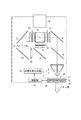
図1は3板式カラー液晶プロジェクタの光学系を示した図である。光源1の発光部2は、超高圧水銀ランプ、メタルハライドランプ、キセノンランプ等から成り、その照射光は、例えばパラボラリフレクタ3によって平行光となって出射される。
【0013】
第1ダイクロイックミラー5は、赤色波長帯域の光を透過し、シアン(緑+青)の波長帯域の光を反射する。第1ダイクロイックミラー5を透過した赤色波長帯域の光は、全反射ミラー6にて反射されて光路を変更される。全反射ミラー6にて反射された赤色光はコンデンサレンズ7を経て赤色光用の透過型の液晶ライトバルブ31を透過することによって光変調される。一方、第1ダイクロイックミラー5にて反射したシアンの波長帯域の光は、第2ダイクロイックミラー8に導かれる。
【0014】
第2ダイクロイックミラー8は、青色波長帯域の光を透過し、緑色波長帯域の光を反射する。第2ダイクロイックミラー8にて反射した緑色波長帯域の光はコンデンサレンズ9を経て緑色光用の透過型の液晶ライトバルブ32に導かれ、これを透過することによって光変調される。また、第2ダイクロイックミラー8を透過した青色波長帯域の光は、全反射ミラー11,13、リレーレンズ10,12、及びコンデンサレンズ14を経て青色光用の透過型の液晶ライトバルブ33に導かれ、これを透過することによって光変調される。
【0015】
上記の液晶ライトバルブ31,32,33は、入射側偏光板と、一対のガラス基板(画素電極や配向膜を形成してある)間に液晶を封入して成るパネル部と、出射側偏光板とを備えて成る。液晶ライトバルブ31,32,33を経ることで変調された変調光(各色映像光)は、ダイクロイックプリズム15によって合成されてカラー映像光となる。このカラー映像光は、投写レンズ16によって拡大投写され、図示しないスクリーン上に投影表示される。
【0016】
前記光源1の後方位置には、イオン風発生装置20が設けられている。このイオン風発生装置20は、図2にも示すように、マイナス側となる多数の針状電極21…でコロナ放電によって空気をマイナスイオン化し、このマイナスイオン化した空気をアース側となるメッシュ電極22で引き寄せて空気移動を生じさせる構成となっている。高電圧発生回路26は、図示しない電源部から電圧供給を受け、マイナス数kV乃至マイナス十数kV程度の高電圧を発生させてこれを電極21…に印加する。
【0017】
また、図1に示したように、イオン風発生装置20の送風口は筐体背面の排気口に向けられており、イオン風発生装置20Aにて生成される移動空気が装置外に排出されるとき、光源1の熱にて高温化した周囲空気が吸引され、移動空気に乗って装置外へと排気される。
【0018】
前記筐体背面の排気口にはオゾン分解触媒フィルタ23を設けている。このオゾン分解触媒フィルタ23は二酸化マンガンや酸化ニッケルなどの触媒を例えばハニカム構造の通気支持体に添着して成るものである。イオン風発生装置20におけるコロナ放電によってオゾン(O3 )が発生し、このオゾンは移動空気に乗って装置外へと導かれることになるが、上記排気口に設けられたオゾン分解触媒フィルタ23を通ることにより、オゾンは分解される。
【0019】
オゾン分解触媒フィルタ23がそのオゾン分解能力を十分に発揮するためにはある程度の温度が必要である。上記の構成では、光源1の熱にて高温化した周囲空気が移動空気に乗って装置外へと排気され、この高温の空気の熱がオゾン分解触媒フィルタ23に付与されるため、オゾン分解触媒フィルタ23は昇温し、そのオゾン分解能力を高めることになる。また、光源1をコールドランプ(リフレクタが赤外線を透過させるタイプ)とすれば、光源1から発せられる赤外線によってもオゾン分解触媒フィルタ23が昇温され、そのオゾン分解能力を高めることになる(光源1から発せられる赤外線を積極的にオゾン分解触媒フィルタ23に導くように、赤外線反射ミラー等を設けることとしてもよい)。ただし、光源点灯直後においてはオゾン分解触媒フィルタ23の温度は室温と同じであり、オゾン分解能力を十分に発揮することができない。そこで、以下に示す制御を行なうこととし、このために温度センサ24及び制御部25を設けている。
【0020】
温度センサ24はオゾン分解触媒フィルタ23の温度またはその周囲温度を検出する。この検出結果(電圧値)は制御部25に与えられる。制御部25は検出温度が規定温度以上となったときにイオン風発生装置20を作動させるよう高電圧発生回路26に対してON指令を与え、規定温度未満となったときにイオン風発生装置20を停止させるよう高電圧発生回路26に対してOFF指令を与えるようになっている。前記規定温度は、用いる触媒によっても異なることとなるし、プロジェクタにおける光学要素の耐熱温度によっても異なることとなるが、例えば、70℃〜90℃とすることができる。
【0021】
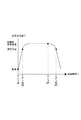
図3は時間経過と装置内温度の変化を示すと共に、光源1のON/OFF及びイオン風発生装置20のON/OFFタイミングを示している。光源1のON当初の装置内温度は室温と同じであるが、その後は光源1の発する熱で装置内温度は上昇し、これと共にオゾン分解触媒フィルタ23の温度も上昇する。検出温度が規定温度以上になるとイオン風発生装置20がONされ、装置内温度はイオン風冷却によって定常温度に維持される。そして、光源1がOFFされた当初はまだ装置内温度は高く、従ってオゾン分解触媒フィルタ23の温度も高いため、しばらくはイオン風発生装置20のON状態が維持され、その後に検出温度が規定温度未満になるとイオン風発生装置20のOFFが行なわれる。このように、温度検出によってイオン風発生装置20をON/OFFするので、オゾン分解触媒フィルタ23のオゾン除去能力が十分に発揮される段階になってから送風を行なうことができ、発生オゾンの装置外への排出を極力抑えることができることになる。
【0022】
以上の例では、イオン風発生装置20によるイオン風にて光源1の周囲の高温空気を吸引して装置外へと導くこととしたが、イオン風発生装置20によるイオン風を光源1に吹きつける構成としてもよく、この場合にはオゾン分解触媒フィルタ23を光源1のリフレクタ3直ぐ近傍に配置するのがよい。また、イオン風発生装置20を光源1の近傍に配置した構成を示したが、これに限るものではなく、他の高温発生箇所(例えば、液晶表示パネルの近傍位置等)に設けてもよいものである。また、イオン風発生装置における電極のプラスとマイナスの関係を逆にしてもかまわないものであり、また、空気や空気中の分子のイオン化で空気移動が生じるものであれば、上述の具体的に示した構成とは異なるイオン風発生装置を用いることができる。また、上記の例においては、温度センサ24によりオゾン分解触媒フィルタ23の温度またはその周辺温度を測定してイオン風発生装置20を操作することとしたが、例えば、光源1がONされた後、タイマー計測をおこない、所定期間が経過したときに、イオン風発生装置20をONし、また、光源1がOFFされた後、タイマー計測をおこない、所定期間が経過したときに、イオン風発生装置20をOFFされることとしてもよいものである。かかる場合も、オゾン分解触媒フィルタ23のオゾン除去能力が十分に発揮される段階になってから送風を行なうことができ、発生オゾンの装置外への排出を極力抑えることができることになる。
【0023】
また、上記の例では、透過型の液晶表示パネルを3枚用いた映像生成光学系を示したが、このような映像生成光学系に限るものではなく、他の映像生成光学系を用いる場合にも適用することができる。
【0024】
【発明の効果】
以上説明したように、この発明によれば、送風装置はイオン化した空気等を電気的に移動させて空気移動を生じさせるから、ファンの回転による送風と異なり、回転騒音の発生は無くなり、吸排気において殆ど無音状態とすることが可能となる。そして、上記イオン化によりオゾンが発生しても、このオゾンはオゾン除去フィルタによって除去されることになる。装置内で発生した熱がオゾン除去フィルタに与えられる構成であれば、オゾン除去フィルタがその除去能力を十分に発揮するためにある程度高温となることが必要となる場合に好都合となる。温度検出によって送風装置をON/OFFする構成やタイマーでON/OFFする構成であれば、オゾン除去フィルタのオゾン除去能力が十分に発揮される段階になってから送風を行なうことができ、発生オゾンの装置外への排出を極力抑えることができることになる。
【図面の簡単な説明】
【図1】この発明の実施形態の投写型映像表示装置を示した図である。
【図2】イオン風発生装置の構成を示した説明図である。
【図3】イオン風発生装置のON/OFF制御を説明する説明図である。
【符号の説明】
1 光源
17 紫外線反射ミラー
20 イオン風発生装置
21 針状電極
22 メッシュ電極
23 オゾン分解触媒フィルタ
24 温度センサ
25 制御部
26 高電圧発生回路[0001]
[Industrial application fields]
The present invention relates to a projection display apparatus such as a liquid crystal projector.
[0002]
[Prior art]
Since the projection display apparatus is configured to modulate and project the light emitted from the light source by a light valve such as a liquid crystal panel, it is necessary to provide a high-intensity light source, which is generated from the high-intensity light source itself. It is necessary to take measures against heat and heat generated when light is absorbed by the polarizing plate of the liquid crystal panel or various optical components. Conventionally, the fan is rotated by a motor to perform intake and exhaust, and heat is removed from the device. It was made to discharge | release (refer patent document 1).
[0003]
[Patent Document 1]
Japanese Patent Laid-Open No. 2001-2222065
[Problems to be solved by the invention]
However, the intake / exhaust mechanism driven by the motor has a disadvantage that noise due to the intake / exhaust sound is generated by the motor rotation sound and the wind noise generated by the fan, and the intake / exhaust sound noise becomes annoying when the projector is used.
[0005]
In view of the above circumstances, an object of the present invention is to provide a projection display apparatus that can substantially eliminate the generation of sound during intake and exhaust.
[0006]
[Means for Solving the Problems]
In order to solve the above-described problem, the projection display apparatus of the present invention is a projection display apparatus that projects light modulated by a light valve using a light valve. An ion wind generator for moving air generated by ionizing the gas by the other electrode is provided, and ozone removing means is provided on the path of the moving air.
[0007]
With the above configuration, the ion wind generator causes air movement by electrically moving ionized air or the like. Therefore, unlike blowing by rotation of the fan, the generation of rotational noise is eliminated, and almost no noise is generated in intake and exhaust. It becomes possible to be in a state. And even if ozone generate | occur | produces by the said ionization, this ozone will be removed by an ozone removal means.
[0008]
You may provide an ozone removal filter on the path | route of the moving air which took the heat which generate | occur | produces in an apparatus and was warmed. Further, an ozone removal filter may be provided on the moving air path and in the vicinity of the light source. Moreover, the reflector which comprises the said light source may permeate | transmit infrared rays, and it may be comprised so that the said infrared rays may be guide | induced to an ozone removal filter. These configurations are advantageous when the ozone removal filter needs to have a certain high temperature in order to fully exhibit its removal capability.
[0009]
A sensor for detecting the temperature of the ozone removing means or the ambient temperature thereof, and the ion wind generator is turned on when the temperature exceeds a specified temperature, and the ion wind generator is turned off when the temperature becomes lower than the specified temperature. And a control means. According to this, ventilation is performed after the ozone removal capability of the ozone removal filter is sufficiently exerted, and the discharge of generated ozone to the outside of the apparatus can be suppressed as much as possible.
[0010]
Further, it is preferable that the ion wind generator is turned on / off when a predetermined period elapses after the light source is turned on / off. Even in such a configuration, air is blown after the ozone removal capability of the ozone removal filter is sufficiently exerted, and discharge of generated ozone to the outside of the apparatus can be suppressed as much as possible.
[0011]
DETAILED DESCRIPTION OF THE INVENTION
Hereinafter, a projection display apparatus according to an embodiment of the present invention will be described with reference to FIGS.
[0012]
FIG. 1 is a diagram showing an optical system of a three-plate color liquid crystal projector. The
[0013]
The first
[0014]
The second dichroic mirror 8 transmits light in the blue wavelength band and reflects light in the green wavelength band. The light in the green wavelength band reflected by the second dichroic mirror 8 is guided to the transmissive liquid
[0015]
The liquid
[0016]
An
[0017]
Further, as shown in FIG. 1, the air blowing port of the ion
[0018]
An ozone
[0019]
In order for the ozonolysis catalyst filter 23 to fully exhibit its ozonolysis ability, a certain temperature is required. In the above configuration, the ambient air heated to high temperature by the heat of the
[0020]
The
[0021]
FIG. 3 shows the passage of time and the change in temperature in the apparatus, as well as the ON / OFF timing of the
[0022]
In the above example, the high-temperature air around the
[0023]
In the above example, an image generation optical system using three transmissive liquid crystal display panels is shown. However, the image generation optical system is not limited to such an image generation optical system, and other image generation optical systems are used. Can also be applied.
[0024]
【The invention's effect】
As described above, according to the present invention, since the air blower causes air movement by electrically moving ionized air or the like, unlike the air blowing due to the rotation of the fan, the generation of rotational noise is eliminated, and the intake and exhaust air is exhausted. It is possible to make the sound almost silent. And even if ozone generate | occur | produces by the said ionization, this ozone will be removed by an ozone removal filter. The configuration in which the heat generated in the apparatus is applied to the ozone removal filter is advantageous when the ozone removal filter needs to have a certain high temperature in order to fully exhibit its removal capability. If the air blower is turned on / off by temperature detection or turned on / off by a timer, the air can be blown after the ozone removal capability of the ozone removal filter is fully demonstrated. Can be suppressed as much as possible.
[Brief description of the drawings]
FIG. 1 is a diagram showing a projection display apparatus according to an embodiment of the present invention.
FIG. 2 is an explanatory diagram showing a configuration of an ion wind generator.
FIG. 3 is an explanatory diagram for explaining ON / OFF control of an ion wind generator.
[Explanation of symbols]
DESCRIPTION OF
Claims (3)
Priority Applications (6)
| Application Number | Priority Date | Filing Date | Title |
|---|---|---|---|
| JP2002361140A JP3717885B2 (en) | 2002-12-12 | 2002-12-12 | Projection display device |
| US10/538,512 US7407293B2 (en) | 2002-12-12 | 2003-12-11 | Projection type image display unit |
| DE60335962T DE60335962D1 (en) | 2002-12-12 | 2003-12-11 | IMAGE DISPLAY UNIT OF THE PROJECTION TYPE |
| EP03778848A EP1571489B1 (en) | 2002-12-12 | 2003-12-11 | Projection type image display unit |
| CN200380104684XA CN1720481B (en) | 2002-12-12 | 2003-12-11 | Projection type image display unit |
| PCT/JP2003/015911 WO2004053590A1 (en) | 2002-12-12 | 2003-12-11 | Projection type image display unit |
Applications Claiming Priority (1)
| Application Number | Priority Date | Filing Date | Title |
|---|---|---|---|
| JP2002361140A JP3717885B2 (en) | 2002-12-12 | 2002-12-12 | Projection display device |
Publications (3)
| Publication Number | Publication Date |
|---|---|
| JP2004191767A JP2004191767A (en) | 2004-07-08 |
| JP2004191767A5 JP2004191767A5 (en) | 2005-06-23 |
| JP3717885B2 true JP3717885B2 (en) | 2005-11-16 |
Family
ID=32501030
Family Applications (1)
| Application Number | Title | Priority Date | Filing Date |
|---|---|---|---|
| JP2002361140A Expired - Fee Related JP3717885B2 (en) | 2002-12-12 | 2002-12-12 | Projection display device |
Country Status (6)
| Country | Link |
|---|---|
| US (1) | US7407293B2 (en) |
| EP (1) | EP1571489B1 (en) |
| JP (1) | JP3717885B2 (en) |
| CN (1) | CN1720481B (en) |
| DE (1) | DE60335962D1 (en) |
| WO (1) | WO2004053590A1 (en) |
Families Citing this family (21)
| Publication number | Priority date | Publication date | Assignee | Title |
|---|---|---|---|---|
| JP3584031B2 (en) * | 2002-03-28 | 2004-11-04 | 三洋電機株式会社 | Projection type video display |
| JP4148865B2 (en) * | 2003-09-26 | 2008-09-10 | 三洋電機株式会社 | Projection display device |
| JP2005275200A (en) | 2004-03-26 | 2005-10-06 | Sanyo Electric Co Ltd | Projection type image display device |
| US20100033688A1 (en) * | 2005-01-21 | 2010-02-11 | Ryozo Obama | Light-source unit, light-source apparatus, and projection-type display apparatus |
| US7830643B2 (en) | 2006-01-23 | 2010-11-09 | Igo, Inc. | Power supply with electrostatic cooling fan |
| WO2007112763A1 (en) * | 2006-04-03 | 2007-10-11 | Aureola Swedish Engineering Ab | Method and apparatus for cooling and ventilation |
| EP1901352A1 (en) * | 2006-09-12 | 2008-03-19 | Neng Tyi Precision Industries Co., Ltd. | Heat sink device generating an ionic wind |
| JP5216280B2 (en) * | 2007-08-23 | 2013-06-19 | 三洋電機株式会社 | Filter clogging detection mechanism and projection display apparatus using the same |
| DE102008010944B4 (en) * | 2008-02-25 | 2010-05-20 | Fujitsu Siemens Computers Gmbh | Cooling arrangement comprising an ion cooling system for an electronic device, electronic device and method for monitoring an electrostatic charge |
| JP2009251133A (en) * | 2008-04-03 | 2009-10-29 | Hitachi Ltd | Projection type video display apparatus |
| JP5136266B2 (en) * | 2008-07-30 | 2013-02-06 | セイコーエプソン株式会社 | Spatial light modulator, projector, and cooling method of spatial light modulator |
| US20100116460A1 (en) * | 2008-11-10 | 2010-05-13 | Tessera, Inc. | Spatially distributed ventilation boundary using electrohydrodynamic fluid accelerators |
| US20110037367A1 (en) * | 2009-08-11 | 2011-02-17 | Ventiva, Inc. | Solid-state light bulb having ion wind fan and internal heat sinks |
| JP5469957B2 (en) * | 2009-08-20 | 2014-04-16 | セイコーエプソン株式会社 | Evaluation method, display sheet manufacturing method, and display sheet manufacturing apparatus |
| US20110198978A1 (en) * | 2010-10-12 | 2011-08-18 | Ventiva, Inc. | Touch-safe solid-state light bulb having ion wind fan |
| CN103197495B (en) * | 2012-01-04 | 2015-06-10 | 中强光电股份有限公司 | Gas filtration module and projecting device |
| CN103698966B (en) * | 2012-09-27 | 2016-08-17 | 中强光电股份有限公司 | Illuminator and projection arrangement |
| JP2014209183A (en) * | 2013-03-27 | 2014-11-06 | セイコーエプソン株式会社 | Air filter and projector |
| CN110291179B (en) | 2017-02-13 | 2021-11-16 | 联合利华知识产权控股有限公司 | Laundry adjunct composition |
| WO2018145896A1 (en) * | 2017-02-13 | 2018-08-16 | Unilever Plc | Method of delivering a laundry composition |
| WO2018145898A1 (en) | 2017-02-13 | 2018-08-16 | Unilever Plc | Laundry composition additive |
Family Cites Families (17)
| Publication number | Priority date | Publication date | Assignee | Title |
|---|---|---|---|---|
| US3899684A (en) * | 1974-06-03 | 1975-08-12 | Ozone Inc | Control system for corona discharge ozone generating unit |
| US4812711A (en) * | 1985-06-06 | 1989-03-14 | Astra-Vent Ab | Corona discharge air transporting arrangement |
| SE458077B (en) * | 1987-07-03 | 1989-02-20 | Astra Vent Ab | DEVICE FOR TRANSPORT AND EVEN CLEANING OF AIR |
| SE462739B (en) * | 1988-12-08 | 1990-08-27 | Astra Vent Ab | DEVICE OF A CORONA DISCHARGE DEVICE FOR THE REMOVAL OF THE DAMAGE ADDITION CREATING HARMFUL SUBSTANCES |
| IL103867A0 (en) * | 1992-11-25 | 1993-04-04 | Spectronix Ltd | Cooling method and apparatus |
| JPH0817356A (en) * | 1994-07-04 | 1996-01-19 | Toshimi Onodera | Blower |
| US6056405A (en) * | 1998-10-15 | 2000-05-02 | In Focus Systems, Inc. | Lamp module with kinematic mount |
| JP2001068293A (en) * | 1999-06-25 | 2001-03-16 | Toto Ltd | Dust adhesion preventing unit and image device with dust adhesion preventing unit |
| JP2001222065A (en) | 2000-02-07 | 2001-08-17 | Sanyo Electric Co Ltd | Electronic apparatus having cooling fan |
| JP2001259470A (en) | 2000-03-16 | 2001-09-25 | Denso Corp | Air cleaner |
| JP3477424B2 (en) | 2000-04-11 | 2003-12-10 | シャープ株式会社 | Shading reflector and image projection device having shading reflector |
| JP3698054B2 (en) * | 2000-12-20 | 2005-09-21 | ソニー株式会社 | Projection display |
| JP2002286904A (en) * | 2001-03-27 | 2002-10-03 | Seiko Epson Corp | Optical parts and projector using the same |
| JP2003195420A (en) * | 2001-12-27 | 2003-07-09 | Tamron Co Ltd | Cooling device for projector |
| JP3584031B2 (en) * | 2002-03-28 | 2004-11-04 | 三洋電機株式会社 | Projection type video display |
| JP4148865B2 (en) * | 2003-09-26 | 2008-09-10 | 三洋電機株式会社 | Projection display device |
| JP2005275200A (en) * | 2004-03-26 | 2005-10-06 | Sanyo Electric Co Ltd | Projection type image display device |
-
2002
- 2002-12-12 JP JP2002361140A patent/JP3717885B2/en not_active Expired - Fee Related
-
2003
- 2003-12-11 EP EP03778848A patent/EP1571489B1/en not_active Expired - Lifetime
- 2003-12-11 DE DE60335962T patent/DE60335962D1/en not_active Expired - Lifetime
- 2003-12-11 US US10/538,512 patent/US7407293B2/en not_active Expired - Fee Related
- 2003-12-11 WO PCT/JP2003/015911 patent/WO2004053590A1/en active Application Filing
- 2003-12-11 CN CN200380104684XA patent/CN1720481B/en not_active Expired - Fee Related
Also Published As
| Publication number | Publication date |
|---|---|
| CN1720481B (en) | 2012-01-25 |
| US7407293B2 (en) | 2008-08-05 |
| WO2004053590A1 (en) | 2004-06-24 |
| JP2004191767A (en) | 2004-07-08 |
| EP1571489A1 (en) | 2005-09-07 |
| EP1571489B1 (en) | 2011-02-02 |
| DE60335962D1 (en) | 2011-03-17 |
| US20060017889A1 (en) | 2006-01-26 |
| CN1720481A (en) | 2006-01-11 |
| EP1571489A4 (en) | 2008-03-19 |
Similar Documents
| Publication | Publication Date | Title |
|---|---|---|
| JP3717885B2 (en) | Projection display device | |
| US7325931B2 (en) | Projection type video display | |
| US20090040468A1 (en) | Image projection apparatus | |
| US7993010B2 (en) | Light source compartment storing light source unit and projector including the same light source compartment | |
| JP4148865B2 (en) | Projection display device | |
| JP3584031B2 (en) | Projection type video display | |
| JP2006091612A (en) | Projection type video display device | |
| JP4030325B2 (en) | Projection display device | |
| JP4155255B2 (en) | Projector device | |
| JP2001296607A (en) | Light-shielding reflector and image projector having the light-shielding reflector | |
| JP2010008627A (en) | Projection-type image display apparatus | |
| JP2007047843A (en) | Projection video display device | |
| US20140313427A1 (en) | Projector | |
| JP3977054B2 (en) | Projector device | |
| JP3953451B2 (en) | Dust collector blower and projection display | |
| JP2006145898A (en) | Projector | |
| JP2007206604A (en) | Projector | |
| JP2005352340A (en) | Dust collector and projection video display device | |
| JP2011075732A (en) | Projection display device | |
| JPH10186546A (en) | Liquid crystal projector | |
| JP4128155B2 (en) | Projection display device | |
| JP2007219153A (en) | Projector | |
| JP2005077891A (en) | Projection type image display device | |
| JP2010243915A (en) | Illuminating device and projection type image display apparatus | |
| JP2011180187A (en) | Projection type image display device |
Legal Events
| Date | Code | Title | Description |
|---|---|---|---|
| A521 | Written amendment |
Free format text: JAPANESE INTERMEDIATE CODE: A523 Effective date: 20040928 |
|
| A621 | Written request for application examination |
Free format text: JAPANESE INTERMEDIATE CODE: A621 Effective date: 20040930 |
|
| A871 | Explanation of circumstances concerning accelerated examination |
Free format text: JAPANESE INTERMEDIATE CODE: A871 Effective date: 20040930 |
|
| A975 | Report on accelerated examination |
Free format text: JAPANESE INTERMEDIATE CODE: A971005 Effective date: 20041014 |
|
| A131 | Notification of reasons for refusal |
Free format text: JAPANESE INTERMEDIATE CODE: A131 Effective date: 20041026 |
|
| A521 | Written amendment |
Free format text: JAPANESE INTERMEDIATE CODE: A523 Effective date: 20041224 |
|
| A131 | Notification of reasons for refusal |
Free format text: JAPANESE INTERMEDIATE CODE: A131 Effective date: 20050125 |
|
| A02 | Decision of refusal |
Free format text: JAPANESE INTERMEDIATE CODE: A02 Effective date: 20050531 |
|
| A521 | Written amendment |
Free format text: JAPANESE INTERMEDIATE CODE: A523 Effective date: 20050616 |
|
| A911 | Transfer of reconsideration by examiner before appeal (zenchi) |
Free format text: JAPANESE INTERMEDIATE CODE: A911 Effective date: 20050725 |
|
| TRDD | Decision of grant or rejection written | ||
| A01 | Written decision to grant a patent or to grant a registration (utility model) |
Free format text: JAPANESE INTERMEDIATE CODE: A01 Effective date: 20050816 |
|
| A61 | First payment of annual fees (during grant procedure) |
Free format text: JAPANESE INTERMEDIATE CODE: A61 Effective date: 20050831 |
|
| FPAY | Renewal fee payment (event date is renewal date of database) |
Free format text: PAYMENT UNTIL: 20090909 Year of fee payment: 4 |
|
| FPAY | Renewal fee payment (event date is renewal date of database) |
Free format text: PAYMENT UNTIL: 20100909 Year of fee payment: 5 |
|
| FPAY | Renewal fee payment (event date is renewal date of database) |
Free format text: PAYMENT UNTIL: 20100909 Year of fee payment: 5 |
|
| FPAY | Renewal fee payment (event date is renewal date of database) |
Free format text: PAYMENT UNTIL: 20110909 Year of fee payment: 6 |
|
| FPAY | Renewal fee payment (event date is renewal date of database) |
Free format text: PAYMENT UNTIL: 20110909 Year of fee payment: 6 |
|
| FPAY | Renewal fee payment (event date is renewal date of database) |
Free format text: PAYMENT UNTIL: 20120909 Year of fee payment: 7 |
|
| FPAY | Renewal fee payment (event date is renewal date of database) |
Free format text: PAYMENT UNTIL: 20120909 Year of fee payment: 7 |
|
| FPAY | Renewal fee payment (event date is renewal date of database) |
Free format text: PAYMENT UNTIL: 20130909 Year of fee payment: 8 |
|
| LAPS | Cancellation because of no payment of annual fees |