JP3717487B2 - Imaging lens - Google Patents
Imaging lens Download PDFInfo
- Publication number
- JP3717487B2 JP3717487B2 JP2003072214A JP2003072214A JP3717487B2 JP 3717487 B2 JP3717487 B2 JP 3717487B2 JP 2003072214 A JP2003072214 A JP 2003072214A JP 2003072214 A JP2003072214 A JP 2003072214A JP 3717487 B2 JP3717487 B2 JP 3717487B2
- Authority
- JP
- Japan
- Prior art keywords
- lens
- shape
- object side
- optical axis
- image
- Prior art date
- Legal status (The legal status is an assumption and is not a legal conclusion. Google has not performed a legal analysis and makes no representation as to the accuracy of the status listed.)
- Expired - Fee Related
Links
Images


Description
【0001】
【発明の属する技術分野】
本発明は、比較的小さい寸法の像を形成するための撮像レンズに関し、特に小型の撮像装置への搭載に適した撮像レンズに関する。
【0002】
【従来の技術】
従来より、CCD(Charge Coupled Device:電荷結合素子)やCMOS(Complementary Metal Oxide Semiconductor)などの撮像素子を用いた撮像装置が知られている。このような撮像装置では、撮像素子上に被写体像を結像させて、その画像を電子的に読み取ることで撮影がなされる。このような撮像装置は、近年、撮像素子の小型化が進んでいることから、装置全体としても非常に小型化が図られてきている。
【0003】
特に、携帯電話における画像入力用のモジュールカメラやデジタルスチルカメラ(以下、単にデジタルカメラという。)などは、近年、小型化が著しい。これらの小型の撮像装置で使用される撮像レンズは、従来、小型・携帯性を重視して1枚のレンズのみで構成されていることが多い。
【0004】
【発明が解決しようとする課題】
一方で、近年では、撮像素子の性能が向上し、素子全体のサイズを大きくすることなく、小型で高画素化が図られたものが開発されてきている。このような高画素化に伴い、それに使用される撮像レンズについても、従来より高い光学性能が要求され、1枚玉のレンズ構成では十分な性能を満足できないという問題が生じてきている。
【0005】
そこで、近年の撮像素子の高画素化に耐えうる光学性能を得るために、レンズの枚数を増やすことが考えられる。しかしながら、レンズ枚数を増やすことで結像性能を向上させることができる一方、全長の点で不利となり、撮像装置に搭載した場合に、小型・携帯性が失われてしまうおそれがある。従来では、特に、高画素化の図られた小型の撮像装置への搭載に適した性能、すなわち、小型化を図りつつも、十分な結像性能を満足するような撮像レンズの開発が十分になされていない。
【0006】
また、撮像装置用の撮像レンズとしてはその他にも、使用する撮像素子の特性に応じた種々の性能のものが要求される場合がある。例えば、一般にCCDなどの撮像素子を用いた場合、その特性上、光線が撮像面に垂直に近い状態で入射することが望ましい。すなわち、テレセントリック性が確保されていることが望ましい。従って、このような撮像素子の特性に応じた種々の性能の撮像レンズの開発が望まれる。
【0007】
本発明はかかる問題点に鑑みてなされたもので、その目的は、比較的像寸法の小さい、特に小型の撮像装置への搭載に適した性能を得ることができる撮像レンズを提供することにある。
【0008】
【課題を解決するための手段】
本発明の第1ないし第5の観点に係る撮像レンズは、撮像素子上に像を結像させるための2群2枚構成の撮像レンズであって、物体側から順に、第1レンズおよび第2レンズを備え、各レンズを構成する4つの面がすべて非球面形状であり、第1レンズよりも物体側に開口絞りが設けられていることを基本構成とし、かつ、4つの面が以下のように最適化された形状を有する構成となっている。
【0009】
本発明による撮像レンズでは、2群2枚構成で、各レンズを構成する4つの面がすべて非球面形状であることから、小型化を図りつつ、諸収差が良好に補正され、従来の1枚玉の撮像レンズに比べて光学性能の向上が図られる。また、開口絞りが最も物体側に設けられていることにより、テレセントリック性の確保が容易になされる。
【0011】
ここで、本発明の第1の観点に係る撮像レンズは、上記基本構成に加え、第1レンズを、物体側の面の光軸近傍の形状が物体側に凹で、かつ、像側の面の光軸近傍の形状が像側に凹で周辺部の形状が像側に凸である構成とし、第2レンズを、物体側の面の光軸近傍の形状が物体側に凸で周辺部の形状が物体側に凹であり、かつ、像側の面の光軸近傍の形状が像側に凹で周辺部の形状が像側に凸である構成にしたものである(請求項1)。
【0012】
また、本発明の第2の観点に係る撮像レンズは、上記基本構成に加え、第1レンズを、物体側の面の光軸近傍の形状が物体側に凹で、かつ、像側の面の光軸近傍の形状が像側に凹で周辺部の形状が像側に凸である構成とし、第2レンズを、物体側の面の光軸近傍の形状が物体側に凸で周辺部の形状が物体側に凹であり、かつ、像側の面の光軸近傍の形状が像側に凸で、中間部の形状が像側に凹、周辺部の形状が像側に凸である構成にしたものである(請求項2)。
【0013】
また、本発明の第3の観点に係る撮像レンズは、上記基本構成に加え、第1レンズを、物体側の面の光軸近傍の形状が物体側に凸で、かつ、像側の面の光軸近傍の形状が像側に凹で周辺部の形状が像側に凸である構成とし、第2レンズを、物体側の面の光軸近傍の形状が物体側に凸で周辺部の形状が物体側に凹であり、かつ、像側の面の光軸近傍の形状が像側に凸で、中間部の形状が像側に凹、周辺部の形状が像側に凸である構成にしたものである(請求項3)。
【0015】
また、本発明の第4の観点に係る撮像レンズは、上記基本構成に加え、第1レンズを、物体側の面の光軸近傍の形状が物体側に凸で、かつ、像側の面の光軸近傍の形状が像側に凹で周辺部の形状が像側に凸である構成とし、第2レンズを、物体側の面の光軸近傍の形状が物体側に凸で周辺部の形状が物体側に凹であり、かつ、像側の面の光軸近傍の形状が像側に凹で周辺部の形状が像側に凸である構成にしたものである(請求項4)。
【0016】
また、本発明の第5の観点に係る撮像レンズは、上記基本構成に加え、第1レンズを、物体側の面の光軸近傍の形状が物体側に凸で、かつ、像側の面の光軸近傍の形状が像側に凸である構成とし、第2レンズを、物体側の面の光軸近傍の形状が物体側に凸で周辺部の形状が物体側に凹であり、かつ、像側の面の光軸近傍の形状が像側に凹で周辺部の形状が像側に凸である構成にしたものである(請求項5)。この構成とした場合、さらに、
ν1/ν2>1.5 ……(1)
の条件式(1)を満足していることが望ましい(ν1,ν2は、第1レンズおよび第2レンズのアッベ数)。この条件を満足することで、倍率の色収差を補正し易くなる。
【0017】
また、以上の本発明による撮像レンズの各構成において、第1レンズおよび第2レンズを構成する4つの面のうち、少なくとも1面を回折光学面としてもよい。回折光学面を用いることで、倍率の色収差を補正し易くなる。
【0018】
以上の本発明による撮像レンズの各構成を、撮像素子の特性などに応じて適宜選択することで、その撮像素子の特性などに応じた最適な光学性能が得られる。
【0019】
【発明の実施の形態】
以下、本発明の実施の形態について図面を参照して詳細に説明する。
【0020】
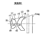
図1〜図9は、本発明の一実施の形態に係る撮像レンズの構成例を示している。図1〜図9に示した構成例は、後述の数値実施例1〜13(図11〜図14)の少なくとも1つに対応している。なお、図1〜図9において、符号ri(r1〜r4)は、i番目の構成要素の面の曲率半径を示し、符号di(d0〜d3)は、i番目の面とi+1番目の面との光軸上の面間隔を示す。図1〜図9には、参考として、最大画角で入射した光線の光路についても示す。
【0021】
図1〜図9に示した本実施の形態に係る撮像レンズは、比較的小さい寸法(例えば直径φ=8mm以下)の像を形成するものであり、特に小型の撮像装置への搭載に適している。
【0022】
この撮像レンズは、光軸Z1に沿って、物体側より順に、第1レンズL1および第2レンズL2を備えた2群2枚構成のレンズとなっている。開口絞りStは、第1レンズL1よりも物体側、すなわち、この撮像レンズの最も物体側に設けられている。この単焦点レンズの結像面Simg(撮像面)には、図示しないCCDなどの撮像素子が配置される。第2レンズL2と結像面Simgとの間には、光学フィルタや撮像素子を保護するためのガラス(またはプラスチック)の平行平面板CGが挿入されていてもよい。
【0023】
第1レンズL1および第2レンズL2は、その4つの面がすべて非球面形状となっている。また、4つの面のうち、少なくとも1面に回折光学面を用いるようにしてもよい。レンズ材料は、光学ガラスまたプラスチックのどちらであっても良い。
【0024】
第1レンズL1および第2レンズL2の形状としては、撮像素子の特性などに応じて、図1〜図9に示した構成のいずれかを選択することができる。
【0025】
なお、以下の構成説明中、“光軸近傍の形状”とは、例えば、画角0°の光線51(図10参照)が通過する範囲内での平均的なレンズ形状のことをいう。また、“周辺部の形状”とは、例えば、最大画角の光線52(図10参照)が通過する範囲内での平均的なレンズ形状のことをいう。また、“中間部の形状”とは、光軸近傍と周辺部との間の領域における平均的なレンズ形状のことをいう。
【0026】
図1に示した撮像レンズは、第1レンズLを、物体側の面の光軸近傍の形状が物体側に凹で、かつ、像側の面の光軸近傍の形状が像側に凸である構成としたものである。また、第2レンズL2を、物体側の面の光軸近傍の形状が物体側に凸で、かつ、像側の面の光軸近傍の形状が像側に凹である構成にしたものである。
【0027】
図2に示した撮像レンズは、第1レンズL1を、物体側の面の光軸近傍の形状が物体側に凹で、かつ、像側の面の光軸近傍の形状が像側に凹で周辺部の形状が像側に凸である構成としたものである。また、第2レンズL2を、物体側の面の光軸近傍の形状が物体側に凸で周辺部の形状が物体側に凹であり、かつ、像側の面の光軸近傍の形状が像側に凹で周辺部の形状が像側に凸である構成にしたものである。
【0028】
図3に示した撮像レンズは、第1レンズL1を、物体側の面の光軸近傍の形状が物体側に凹で、かつ、像側の面の光軸近傍の形状が像側に凹で周辺部の形状が像側に凸である構成としたものである。また、第2レンズL2を、物体側の面の光軸近傍の形状が物体側に凸で周辺部の形状が物体側に凹であり、かつ、像側の面の光軸近傍の形状が像側に凸で、中間部の形状が像側に凹、周辺部の形状が像側に凸である構成にしたものである。
【0029】
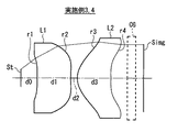
図4に示した撮像レンズは、第1レンズL1を、物体側の面の光軸近傍の形状が物体側に凸で、かつ、像側の面の光軸近傍の形状が像側に凹で周辺部の形状が像側に凸である構成としたものである。また、第2レンズL2を、物体側の面の光軸近傍の形状が物体側に凸で周辺部の形状が物体側に凹であり、かつ、像側の面の光軸近傍の形状が像側に凸で、中間部の形状が像側に凹、周辺部の形状が像側に凸である構成にしたものである。
【0030】
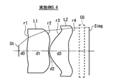
図5および図6に示した撮像レンズは、第1レンズL1を、物体側の面の光軸近傍の形状が物体側に凸で、かつ、像側の面の光軸近傍の形状が像側に凹である構成としたものである。また、第2レンズL2を、物体側の面の光軸近傍の形状が物体側に凸で周辺部の形状が物体側に凹であり、かつ、像側の面の光軸近傍の形状が像側に凹で周辺部の形状が像側に凸である構成にしたものである。
【0031】
図7および図8に示した撮像レンズは、第1レンズL1を、物体側の面の光軸近傍の形状が物体側に凸で、かつ、像側の面の光軸近傍の形状が像側に凹で周辺部の形状が像側に凸である構成としたものである。また、第2レンズL2を、物体側の面の光軸近傍の形状が物体側に凸で周辺部の形状が物体側に凹であり、かつ、像側の面の光軸近傍の形状が像側に凹で周辺部の形状が像側に凸である構成にしたものである。
【0032】
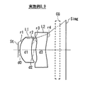
図9に示した撮像レンズは、第1レンズL1を、物体側の面の光軸近傍の形状が物体側に凸で、かつ、像側の面の光軸近傍の形状が像側に凸である構成としたものである。また、第2レンズL2を、物体側の面の光軸近傍の形状が物体側に凸で周辺部の形状が物体側に凹であり、かつ、像側の面の光軸近傍の形状が像側に凹で周辺部の形状が像側に凸である構成にしたものである。
【0033】
図9に示した構成とした場合、さらに、
ν1/ν2>1.5 ……(1)
の条件式(1)を満足していることが望ましい(ν1,ν2は、第1レンズおよび第2レンズのアッベ数)。
【0034】
次に、この撮像レンズの作用および効果について説明する。
【0035】
この撮像レンズでは、2群2枚構成で、各レンズを構成する4つの面をすべて非球面形状にしたことにより、小型化を図りつつ、諸収差を良好に補正することができる。また、開口絞りStを最も物体側に配置したことにより、撮像素子の特性に応じてテレセントリック性の確保がし易くなる。
【0036】
また、各レンズを構成する4つの面のうち、少なくとも1面を回折光学面とすることにより、倍率の色収差を良好に補正することができる。その結果、色のにじみが少なくなり、解像力などの結像性能を向上させることができる。
【0037】
特に、図1の構成にした場合には、以下の作用、効果が得られる。
1.歪曲収差を小さくすることができる。
2.光学系前端から像面までの長さを比較的短くすることができる。
3.像面湾曲を比較的小さくすることができる。
【0038】
また特に、図2〜図4の構成にした場合には、以下の作用、効果が得られる。
1.像面に入射する光束の入射角を小さくし、画面周辺部でも十分な光量を撮像素子で取り込むことができる。
2.像面湾曲を比較的小さくすることができる。
【0039】
また特に、図5および図6の構成にした場合には、以下の作用、効果が得られる。
1.歪曲収差を比較的小さくすることができる。
2.光学系前端から像面までの長さを短くすることができる。
3.単一の材料にしたとしても、倍率の色収差を比較的小さくすることができる。
【0040】
また特に、図7および図8の構成にした場合には、以下の作用、効果が得られる。
1.歪曲収差を比較的小さくすることができる。
2.光学系前端から像面までの長さを比較的短くしながら、像面に入射する光束の入射角を比較的小さくし、画面周辺部でも十分な光量を撮像素子で取り込むことができる。
【0041】
また特に、図9の構成にした場合には、以下の作用、効果が得られる。
1.歪曲収差を比較的小さくすることができる。
2.光学系前端から像面までの長さを比較的短くすることができる
3.像面湾曲を比較的小さくすることができる。
4.コマ収差を十分に小さくすることができ、良好な像が得られる。
【0042】
図9の構成において、アッベ数に関する条件式(1)を満足した場合には、さらに、倍率の色収差を小さくすることができる。
【0043】
このように、本実施の形態に係る撮像レンズによれば、物体側から順に、第1レンズL1および第2レンズL2を備え、各レンズを構成する4つの面をすべて非球面形状とし、第1レンズL1よりも物体側に開口絞りStを設けるようにしたので、比較的像寸法の小さい、特に小型の撮像装置への搭載に適した性能を得ることができる。また、図1〜図9に示した構成を、撮像素子の特性などに応じて適宜選択することで、その撮像素子の特性などに応じた最適な光学性能を得ることができる。
【0044】
【実施例】
次に、上記実施の形態に係る撮像レンズの具体的な数値実施例について説明する。
【0045】
<実施例1〜13>
以下、第1〜第13の数値実施例(実施例1〜13)をまとめて説明する。図11および図12は、実施例1〜6に係る撮像レンズに関するデータを示している。特に、図11には、実施例1〜6に係る撮像レンズについての、曲率半径r1〜r4、面間隔(厚さ)d0〜d3、屈折率N1,N2、アッベ数νd1,νd2、および平行平面板CGとしてのカバーガラスの厚さと屈折率の値を示す。図11にはさらに、Fナンバー、焦点距離f、バックフォーカスBf、画角2ω(ω=半画角)、および、この撮像レンズ光学系の前端から像面までの距離TCLについても示す。また、回折光学面がある場合には、その係数(DOE(Diffractive Optical Element)係数)の値についても示す。また、図12には、非球面形状に関するデータを示す。曲率半径や面間隔の値などの単位はミリメートル(mm)である。
【0046】
また、図11および図12と同様にして、実施例7〜13に係る撮像レンズについてのデータを図13および図14に示す。図13から分かるように、特に実施例12,13については、アッベ数の値の比νd1/νd2が、上述の式(1)の条件を満たしている。
【0047】
ここで、各実施例と図1〜図9に示した構成の対応関係について説明すると、実施例1は、図1に示した構成に対応し、実施例2は、図2に示した構成に対応し、実施例3,4は、図3に示した構成に対応し、実施例5,6は、図4に示した構成に対応している。また、実施例7は、図5に示した構成に対応し、実施例8,9は、図6に示した構成に対応し、実施例10は、図7に示した構成に対応し、実施例11は、図8に示した構成に対応し、実施例12,13は、図9に示した構成に対応している。
【0048】
図12および図14に示した非球面データは、以下の式(A)によって表される非球面形状の式における係数である。なお、図12および図14に示した非球面を表す数値において、記号“E”は、その次に続く数値が10を底とした“べき指数”であることを示し、その10を底とした指数関数で表される数値が“E”の前の数値に乗算されることを示す。例えば、「1.0E−02」であれば、「1.0×10⁻²」であることを示す。
【0049】
【数1】

Z:光軸から高さρの位置にある非球面上の点から、非球面の頂点の接平面(光軸に垂直な平面)に下ろした垂線の長さ(mm)
ρ:光軸からの距離(mm)
K:円錐係数
C:近軸曲率(1/r,r:近軸曲率半径)
Ai:第i次(i=3〜10)の非球面係数
【0050】
実施例4および実施例11については、第1面が回折光学面とされている。回折光学面は、光路長に次の式(B)で表される長さが付加されるような構成となる。
【0051】
(C01・ρ・λ)/2π ……(B)
ただし、
C01:DOE係数
ρ:光軸からの距離(mm)
λ:波長
【0052】
図15〜図27は、各実施例についての諸収差(球面収差、非点収差、歪曲収差および倍率色収差)を示している。各収差は、e線(546.1nm)を基準としたものを示し、特に、球面収差および倍率色収差については、g線(435.8nm),C線(656.3nm)についても示す。
【0053】
以上の各レンズデータおよび各収差図から分かるように、各実施例について、諸収差が良好に補正されており、また、小型の撮像装置への搭載に適した性能が得られている。
【0054】
なお、本発明は、上記実施の形態および各実施例に限定されず種々の変形実施が可能である。例えば、各レンズ成分の曲率半径、面間隔および屈折率の値などは、上記各数値実施例で示した値に限定されず、他の値をとり得る。
【0055】
【発明の効果】
以上説明したように、請求項1ないし7のいずれか1項に記載の撮像レンズによれば、物体側から順に、第1レンズおよび第2レンズを備え、各レンズを構成する4つの面をすべて非球面形状とし、第1レンズよりも物体側に開口絞りを設け、かつ、4つの面の光軸近傍から周辺部までの凹凸形状を最適化するようにしたので、比較的像寸法の小さい、特に小型の撮像装置への搭載に適した性能を得ることができる。特に、2群2枚構成で、各レンズを構成する4つの面をすべて非球面形状にしたことから、小型化を図りつつ、諸収差を良好に補正し、光学性能の向上を図ることができる。また、開口絞りを最も物体側に設けたことにより、テレセントリック性を確保し易くなる。
【0056】
特に、請求項6記載の撮像レンズによれば、請求項5記載の撮像レンズにおいて、アッベ数に関する所定の条件式(1)を満足するようにしたので、さらに、倍率の色収差を小さくすることができる。
【0057】
特に、請求項7記載の撮像レンズによれば、各レンズを構成する4つの面のうち、少なくとも1面を回折光学面にしたので、倍率の色収差を良好に補正することができる。その結果、色のにじみが少なくなり、解像力などの結像性能を向上させることができる。
【図面の簡単な説明】
【図1】本発明の一実施の形態に係る撮像レンズの構成例を示すものであり、実施例1に対応するレンズ断面図図である。
【図2】本発明の一実施の形態に係る撮像レンズの構成例を示すものであり、実施例2に対応するレンズ断面図である。
【図3】本発明の一実施の形態に係る撮像レンズの構成例を示すものであり、実施例3,4に対応するレンズ断面図である。
【図4】本発明の一実施の形態に係る撮像レンズの構成例を示すものであり、実施例5,6に対応するレンズ断面図である。
【図5】本発明の一実施の形態に係る撮像レンズの構成例を示すものであり、実施例7に対応するレンズ断面図である。
【図6】本発明の一実施の形態に係る撮像レンズの構成例を示すものであり、実施例8,9に対応するレンズ断面図である。
【図7】本発明の一実施の形態に係る撮像レンズの構成例を示すものであり、実施例10に対応するレンズ断面図である。
【図8】本発明の一実施の形態に係る撮像レンズの構成例を示すものであり、実施例11に対応するレンズ断面図である。
【図9】本発明の一実施の形態に係る撮像レンズの構成例を示すものであり、実施例12,13に対応するレンズ断面図である。
【図10】本発明の一実施の形態に係る撮像レンズの中心部と周辺部との概念を示す図である。
【図11】本発明の実施例1〜6に係る撮像レンズのレンズデータのうち、基本的なデータを示す説明図である。
【図12】本発明の実施例1〜6に係る撮像レンズのレンズデータのうち、非球面のデータを示す説明図である。
【図13】本発明の実施例7〜13に係る撮像レンズのレンズデータのうち、基本的なデータを示す説明図である。
【図14】本発明の実施例7〜13に係る撮像レンズのレンズデータのうち、非球面のデータを示す説明図である。
【図15】実施例1の撮像レンズについての諸収差を示す図である。
【図16】実施例2の撮像レンズについての諸収差を示す図である。
【図17】実施例3の撮像レンズについての諸収差を示す図である。
【図18】実施例4の撮像レンズについての諸収差を示す図である。
【図19】実施例5の撮像レンズについての諸収差を示す図である。
【図20】実施例6の撮像レンズについての諸収差を示す図である。
【図21】実施例7の撮像レンズについての諸収差を示す図である。
【図22】実施例8の撮像レンズについての諸収差を示す図である。
【図23】実施例9の撮像レンズについての諸収差を示す図である。
【図24】実施例10の撮像レンズについての諸収差を示す図である。
【図25】実施例11の撮像レンズについての諸収差を示す図である。
【図26】実施例12の撮像レンズについての諸収差を示す図である。
【図27】実施例13の撮像レンズについての諸収差を示す図である。
【符号の説明】
L1…第1レンズ、L2…第2レンズ、CG…平行平面板、Z1…光軸。[0001]
BACKGROUND OF THE INVENTION
The present invention relates to an imaging lens for forming an image having a relatively small size, and more particularly to an imaging lens suitable for mounting on a small imaging device.
[0002]
[Prior art]
2. Description of the Related Art Conventionally, an imaging device using an imaging element such as a charge coupled device (CCD) or a complementary metal oxide semiconductor (CMOS) is known. In such an image pickup apparatus, an image of a subject is formed on an image pickup element, and photographing is performed by electronically reading the image. In recent years, such an imaging apparatus has been miniaturized as the entire apparatus because the imaging element has been miniaturized.
[0003]
In particular, module cameras for image input and digital still cameras (hereinafter simply referred to as digital cameras) in mobile phones have been remarkably miniaturized in recent years. Conventionally, an imaging lens used in these small-sized imaging devices is often composed of only one lens with an emphasis on small size and portability.
[0004]
[Problems to be solved by the invention]
On the other hand, in recent years, the performance of an image pickup device has been improved, and a device having a small size and high pixels has been developed without increasing the size of the entire device. With such an increase in the number of pixels, an imaging lens used therefor is also required to have higher optical performance than before, and there is a problem that sufficient performance cannot be satisfied with a single lens configuration.
[0005]
Therefore, it is conceivable to increase the number of lenses in order to obtain optical performance that can withstand the increase in the number of pixels of recent image sensors. However, while the imaging performance can be improved by increasing the number of lenses, it is disadvantageous in terms of the total length, and when mounted on an imaging apparatus, there is a possibility that the small size and portability may be lost. Conventionally, the development of an imaging lens that is particularly suitable for mounting on a small imaging device with a high pixel count, that is, satisfying sufficient imaging performance while achieving downsizing is sufficiently performed. Not done.
[0006]
In addition to the above, an imaging lens for an imaging apparatus may be required to have various performances according to the characteristics of the imaging device to be used. For example, in general, when an image sensor such as a CCD is used, it is desirable that the light beam is incident in a state of being nearly perpendicular to the imaging surface because of its characteristics. That is, it is desirable to ensure telecentricity. Therefore, it is desired to develop imaging lenses having various performances according to the characteristics of such imaging elements.
[0007]
The present invention has been made in view of such problems, and an object thereof is to provide an imaging lens having a relatively small image size and capable of obtaining performance suitable for mounting on a small-sized imaging device. .
[0008]
[Means for Solving the Problems]
The imaging lens according to the first to fifth aspects of the present invention is an imaging lens having a two-group, two-element configuration for forming an image on an imaging element, and the first lens and the second lens are sequentially arranged from the object side. includes a lens, a four surfaces are aspheric shape constituting each lens, the aperture stop is found provided on the object side of the first lens as a basic structure, and the four surfaces below Thus, the configuration has an optimized shape.
[0009]
In the imaging lens according to the present invention, two lenses in two groups, and all four surfaces constituting each lens are aspherical, so that various aberrations are favorably corrected while downsizing and one conventional lens is used. The optical performance is improved as compared with the ball imaging lens. Further, since the aperture stop is provided on the most object side, it is easy to ensure telecentricity.
[0011]
Here, in addition to the above basic configuration, the imaging lens according to the first aspect of the present invention is the same as the first lens in that the shape in the vicinity of the optical axis of the object-side surface is concave on the object side, and the image-side surface The shape near the optical axis is concave on the image side and the shape on the periphery is convex on the image side, and the second lens has a shape near the optical axis on the object side surface and is convex on the object side. shape is concave on the object side, and one in which the shape of the vicinity of the optical axis of the image-side surface of the shape of the peripheral portion in the concave to the image side has a configuration which is convex to the image side (claim 1).
[0012]
In addition to the basic configuration described above, the imaging lens according to the second aspect of the present invention is configured so that the shape of the first lens in the vicinity of the optical axis of the object side surface is concave on the object side, and the surface on the image side is The shape in the vicinity of the optical axis is concave on the image side and the shape of the peripheral portion is convex on the image side, and the second lens has a shape in the vicinity of the optical axis on the object side surface that is convex on the object side and the shape of the peripheral portion Is concave on the object side, and the shape near the optical axis of the image side surface is convex toward the image side, the shape of the intermediate portion is concave toward the image side, and the shape of the peripheral portion is convex toward the image side. in which the (claim 2).
[0013]
In addition to the above basic configuration, the imaging lens according to the third aspect of the present invention includes the first lens in which the shape of the object side surface near the optical axis is convex toward the object side and the image side surface The shape in the vicinity of the optical axis is concave on the image side and the shape of the peripheral portion is convex on the image side, and the second lens has a shape in the vicinity of the optical axis on the object side surface that is convex on the object side and the shape of the peripheral portion Is concave on the object side, and the shape near the optical axis of the image side surface is convex toward the image side, the shape of the intermediate portion is concave toward the image side, and the shape of the peripheral portion is convex toward the image side. in which the (claim 3).
[0015]
An imaging lens according to a fourth aspect of the present invention includes, in addition to the above basic configuration, the first lens having a shape in the vicinity of the optical axis of the object-side surface that is convex toward the object side and an image-side surface. The shape in the vicinity of the optical axis is concave on the image side and the shape of the peripheral portion is convex on the image side, and the second lens has a shape in the vicinity of the optical axis on the object side surface that is convex on the object side and the shape of the peripheral portion There is a concave on the object side, and one in which the shape of the vicinity of the optical axis of the image-side surface of the shape of the peripheral portion in the concave to the image side has a configuration which is convex to the image side (claim 4).
[0016]
An imaging lens according to a fifth aspect of the present invention includes, in addition to the above basic configuration, the first lens having a shape in the vicinity of the optical axis of the object-side surface that is convex toward the object side and an image-side surface. The configuration in which the shape in the vicinity of the optical axis is convex on the image side, the second lens has a shape in the vicinity of the optical axis on the object side surface that is convex on the object side, and the shape of the peripheral portion is concave on the object side, and in which the shape of the vicinity of the optical axis of the image-side surface of the shape of the peripheral portion in the concave to the image side has a configuration which is convex to the image side (claim 5). With this configuration,
ν1 / ν2> 1.5 (1)
It is desirable that the conditional expression (1) is satisfied (ν1 and ν2 are Abbe numbers of the first lens and the second lens). Satisfying this condition makes it easier to correct chromatic aberration of magnification.
[0017]
In each configuration of the imaging lens according to the present invention, at least one of the four surfaces constituting the first lens and the second lens may be a diffractive optical surface. By using a diffractive optical surface, it becomes easy to correct lateral chromatic aberration.
[0018]
By appropriately selecting each configuration of the imaging lens according to the present invention according to the characteristics of the imaging device, the optimum optical performance according to the characteristics of the imaging device can be obtained.
[0019]
DETAILED DESCRIPTION OF THE INVENTION
Hereinafter, embodiments of the present invention will be described in detail with reference to the drawings.
[0020]
FIGS. 1-9 has shown the structural example of the imaging lens which concerns on one embodiment of this invention. The configuration example shown in FIGS. 1 to 9 corresponds to at least one of numerical examples 1 to 13 (FIGS. 11 to 14) described later. 1 to 9, the symbol ri (r1 to r4) represents the radius of curvature of the surface of the i-th component, and the symbol di (d0 to d3) represents the i-th surface and the i + 1-th surface. The surface interval on the optical axis is shown. 1 to 9 also show the optical path of a light beam incident at the maximum angle of view as a reference.
[0021]
The imaging lens according to the present embodiment shown in FIGS. 1 to 9 forms an image having a relatively small size (for example, diameter φ = 8 mm or less), and is particularly suitable for mounting on a small imaging device. Yes.
[0022]
The imaging lens is a two-group, two-lens configuration including a first lens L1 and a second lens L2 in order from the object side along the optical axis Z1. The aperture stop St is provided on the object side of the first lens L1, that is, on the most object side of the imaging lens. An imaging element such as a CCD (not shown) is disposed on the imaging surface Simg (imaging surface) of the single focus lens. Between the second lens L2 and the imaging plane Simg, a glass (or plastic) parallel plane plate CG for protecting the optical filter and the imaging element may be inserted.
[0023]
The four surfaces of the first lens L1 and the second lens L2 are all aspherical. Further, a diffractive optical surface may be used for at least one of the four surfaces. The lens material may be either optical glass or plastic.
[0024]
As the shape of the first lens L1 and the second lens L2, one of the configurations shown in FIGS. 1 to 9 can be selected according to the characteristics of the imaging element.
[0025]
In the following description of the configuration, the “shape near the optical axis” means, for example, an average lens shape within a range through which the light beam 51 (see FIG. 10) having an angle of view of 0 ° passes. Further, the “peripheral shape” means, for example, an average lens shape within a range through which the light beam 52 (see FIG. 10) having the maximum field angle passes. The “intermediate shape” means an average lens shape in a region between the vicinity of the optical axis and the peripheral portion.
[0026]
The imaging lens shown in FIG. 1 has a first lens L in which the shape near the optical axis of the object side surface is concave toward the object side, and the shape near the optical axis of the image side surface is convex toward the image side. It has a certain configuration. Further, the second lens L2 is configured such that the shape of the object side surface near the optical axis is convex toward the object side, and the shape near the optical axis of the image side surface is concave toward the image side. .
[0027]
The imaging lens shown in FIG. 2 is different from the first lens L1 in that the shape near the optical axis of the object side surface is concave on the object side, and the shape near the optical axis of the image side surface is concave on the image side. The shape of the peripheral part is convex on the image side. In addition, the second lens L2 is formed such that the shape of the object side surface near the optical axis is convex toward the object side, the shape of the peripheral portion is concave toward the object side, and the shape near the optical axis of the image side surface is the image. The configuration is concave on the side and the shape of the peripheral portion is convex on the image side.
[0028]
The imaging lens shown in FIG. 3 is different from the first lens L1 in that the shape of the object side surface near the optical axis is concave on the object side, and the shape of the image side surface near the optical axis is concave on the image side. The shape of the peripheral part is convex on the image side. In addition, the second lens L2 is formed such that the shape of the object side surface near the optical axis is convex toward the object side, the shape of the peripheral portion is concave toward the object side, and the shape near the optical axis of the image side surface is the image. Convex to the side, the shape of the middle part is concave to the image side, and the shape of the peripheral part is convex to the image side.
[0029]
In the imaging lens shown in FIG. 4, the shape of the first lens L1 near the optical axis of the object side surface is convex toward the object side, and the shape near the optical axis of the image side surface is concave toward the image side. The shape of the peripheral part is convex on the image side. In addition, the second lens L2 is formed such that the shape of the object side surface near the optical axis is convex toward the object side, the shape of the peripheral portion is concave toward the object side, and the shape near the optical axis of the image side surface is the image. Convex to the side, the shape of the middle part is concave to the image side, and the shape of the peripheral part is convex to the image side.
[0030]
In the imaging lens shown in FIGS. 5 and 6, the first lens L1 has the shape near the optical axis of the object side surface convex toward the object side, and the shape near the optical axis of the image side surface is the image side. The configuration is concave. In addition, the second lens L2 is formed such that the shape of the object side surface near the optical axis is convex toward the object side, the shape of the peripheral portion is concave toward the object side, and the shape near the optical axis of the image side surface is the image. The configuration is concave on the side and the shape of the peripheral portion is convex on the image side.
[0031]
In the imaging lens shown in FIGS. 7 and 8, the first lens L1 is formed such that the shape of the object side surface near the optical axis is convex toward the object side, and the shape of the image side surface near the optical axis is the image side. In this configuration, the shape of the peripheral portion is concave and the shape of the peripheral portion is convex to the image side. In addition, the second lens L2 is formed such that the shape of the object side surface near the optical axis is convex toward the object side, the shape of the peripheral portion is concave toward the object side, and the shape near the optical axis of the image side surface is the image. The configuration is concave on the side and the shape of the peripheral portion is convex on the image side.
[0032]
In the imaging lens shown in FIG. 9, the first lens L1 is formed such that the shape of the object side surface near the optical axis is convex toward the object side, and the shape near the optical axis of the image side surface is convex toward the image side. It has a certain configuration. In addition, the second lens L2 is formed such that the shape of the object side surface near the optical axis is convex toward the object side, the shape of the peripheral portion is concave toward the object side, and the shape near the optical axis of the image side surface is the image. The configuration is concave on the side and the shape of the peripheral portion is convex on the image side.
[0033]
In the case of the configuration shown in FIG.
ν1 / ν2> 1.5 (1)
It is desirable that the conditional expression (1) is satisfied (ν1 and ν2 are Abbe numbers of the first lens and the second lens).
[0034]
Next, functions and effects of the imaging lens will be described.
[0035]
In this imaging lens, two lenses in two groups are configured so that all four surfaces constituting each lens are aspherical, so that various aberrations can be favorably corrected while downsizing. In addition, since the aperture stop St is disposed closest to the object side, it is easy to ensure telecentricity according to the characteristics of the image sensor.
[0036]
Further, by making at least one of the four surfaces constituting each lens a diffractive optical surface, it is possible to satisfactorily correct lateral chromatic aberration. As a result, color bleeding is reduced and imaging performance such as resolving power can be improved.
[0037]
In particular, when the configuration shown in FIG. 1 is used, the following actions and effects can be obtained.
1. Distortion can be reduced.
2. The length from the front end of the optical system to the image plane can be made relatively short.
3. The field curvature can be made relatively small.
[0038]
In particular, when the configuration shown in FIGS. 2 to 4 is used, the following actions and effects can be obtained.
1. The incident angle of the light beam incident on the image plane can be reduced, and a sufficient amount of light can be captured by the image sensor even at the periphery of the screen.
2. The field curvature can be made relatively small.
[0039]
In particular, when the configuration shown in FIGS. 5 and 6 is used, the following actions and effects can be obtained.
1. Distortion aberration can be made relatively small.
2. The length from the front end of the optical system to the image plane can be shortened.
3. Even if a single material is used, the chromatic aberration of magnification can be made relatively small.
[0040]
In particular, when the configuration shown in FIGS. 7 and 8 is used, the following actions and effects can be obtained.
1. Distortion aberration can be made relatively small.
2. While the length from the front end of the optical system to the image plane is relatively short, the incident angle of the light beam incident on the image plane is relatively small, and a sufficient amount of light can be captured by the image sensor even at the periphery of the screen.
[0041]
In particular, when the configuration shown in FIG. 9 is used, the following actions and effects can be obtained.
1. Distortion aberration can be made relatively small.
2. 2. The length from the front end of the optical system to the image plane can be made relatively short. The field curvature can be made relatively small.
4). The coma aberration can be made sufficiently small, and a good image can be obtained.
[0042]
In the configuration of FIG. 9, when the conditional expression (1) regarding the Abbe number is satisfied, the chromatic aberration of magnification can be further reduced.
[0043]
Thus, according to the imaging lens according to the present embodiment, the first lens L1 and the second lens L2 are provided in order from the object side, and all four surfaces constituting each lens are aspherical, and the first Since the aperture stop St is provided on the object side with respect to the lens L1, it is possible to obtain performance suitable for mounting on a particularly small image pickup apparatus having a relatively small image size. In addition, by appropriately selecting the configuration shown in FIGS. 1 to 9 according to the characteristics of the image sensor, it is possible to obtain optimum optical performance according to the characteristics of the image sensor.
[0044]
【Example】
Next, specific numerical examples of the imaging lens according to the above embodiment will be described.
[0045]
<Examples 1 to 13>
Hereinafter, the first to thirteenth numerical examples (Examples 1 to 13) will be described together. 11 and 12 show data related to the imaging lens according to Examples 1-6. In particular, FIG. 11 shows curvature radii r1 to r4, surface spacing (thickness) d0 to d3, refractive indexes N1 and N2, Abbe numbers νd1 and νd2, and parallel planes for the imaging lenses according to Examples 1 to 6. The value of the thickness and refractive index of the cover glass as the face plate CG is shown. FIG. 11 further shows the F number, focal length f, back focus Bf, field angle 2ω (ω = half field angle), and distance TCL from the front end of the imaging lens optical system to the image plane. Further, when there is a diffractive optical surface, the value of the coefficient (DOE (Diffractive Optical Element) coefficient) is also shown. FIG. 12 shows data related to the aspheric shape. Units such as the value of the radius of curvature and the surface interval are millimeters (mm).
[0046]
Similarly to FIGS. 11 and 12, data on the imaging lenses according to Examples 7 to 13 are shown in FIGS. As can be seen from FIG. 13, especially in Examples 12 and 13, the Abbe number ratio νd1 / νd2 satisfies the condition of the above-described formula (1).
[0047]
Here, the correspondence between each embodiment and the configuration shown in FIGS. 1 to 9 will be described. The first embodiment corresponds to the configuration shown in FIG. 1, and the second embodiment has the configuration shown in FIG. Correspondingly, the third and fourth embodiments correspond to the configuration shown in FIG. 3, and the fifth and sixth embodiments correspond to the configuration shown in FIG. Further, Example 7 corresponds to the configuration shown in FIG. 5, Examples 8 and 9 correspond to the configuration shown in FIG. 6, and Example 10 corresponds to the configuration shown in FIG. Example 11 corresponds to the configuration shown in FIG. 8, and Examples 12 and 13 correspond to the configuration shown in FIG.
[0048]
The aspheric data shown in FIGS. 12 and 14 are coefficients in the aspherical shape expression represented by the following expression (A). In the numerical values representing the aspherical surfaces shown in FIG. 12 and FIG. 14, the symbol “E” indicates that the subsequent numerical value is a “power index” with 10 as the base, and 10 is the base. Indicates that the numerical value represented by the exponential function is multiplied by the numerical value before “E”. For example, “1.0E-02” indicates “1.0 × 10 −2 ”.
[0049]
[Expression 1]
Z: Length of a perpendicular line (mm) drawn from a point on the aspheric surface at a height ρ from the optical axis to the tangent plane (plane perpendicular to the optical axis) of the apex of the aspheric surface
ρ: Distance from optical axis (mm)
K: Conic coefficient C: Paraxial curvature (1 / r, r: Paraxial radius of curvature)
Ai: i-th order (i = 3 to 10) aspheric coefficient
In Example 4 and Example 11, the first surface is a diffractive optical surface. The diffractive optical surface is configured such that the length represented by the following formula (B) is added to the optical path length.
[0051]
(C01 · ρ · λ) / 2π (B)
However,
C01: DOE coefficient ρ: distance from the optical axis (mm)
λ: Wavelength [0052]
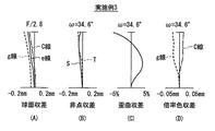
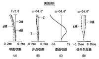
15 to 27 show various aberrations (spherical aberration, astigmatism, distortion and lateral chromatic aberration) for each example. Each aberration is based on e-line (546.1 nm), and in particular, spherical aberration and lateral chromatic aberration are also shown for g-line (435.8 nm) and C-line (656.3 nm).
[0053]
As can be seen from the lens data and aberration diagrams described above, various aberrations are well corrected for each example, and performance suitable for mounting in a small imaging device is obtained.
[0054]
In addition, this invention is not limited to the said embodiment and each Example, A various deformation | transformation implementation is possible. For example, the radius of curvature, the surface interval, and the refractive index of each lens component are not limited to the values shown in the above numerical examples, and may take other values.
[0055]
【The invention's effect】
As described above, according to the imaging lens according to any one of
[0056]
In particular, according to the imaging lens of the sixth aspect, in the imaging lens of the fifth aspect , since the predetermined conditional expression (1) regarding the Abbe number is satisfied, the chromatic aberration of magnification can be further reduced. it can.
[0057]
In particular, according to the imaging lens of the seventh aspect, since at least one of the four surfaces constituting each lens is a diffractive optical surface, the chromatic aberration of magnification can be corrected well. As a result, color bleeding is reduced and imaging performance such as resolving power can be improved.
[Brief description of the drawings]
FIG. 1 illustrates a configuration example of an imaging lens according to an embodiment of the present invention, and is a lens cross-sectional view corresponding to Example 1. FIG.
FIG. 2 illustrates a configuration example of an imaging lens according to an embodiment of the present invention, and is a lens cross-sectional view corresponding to Example 2;
FIG. 3 illustrates a configuration example of an imaging lens according to an embodiment of the present invention, and is a lens cross-sectional view corresponding to Examples 3 and 4;
4 is a lens cross-sectional view illustrating a configuration example of an imaging lens according to an embodiment of the present invention and corresponding to Examples 5 and 6. FIG.
FIG. 5 is a lens cross-sectional view illustrating a configuration example of an imaging lens according to an embodiment of the present invention and corresponding to Example 7;
FIG. 6 illustrates a configuration example of an imaging lens according to an embodiment of the present invention, and is a lens cross-sectional view corresponding to Examples 8 and 9.
7 is a lens cross-sectional view illustrating a configuration example of an imaging lens according to an embodiment of the present invention and corresponding to Example 10. FIG.
8 is a lens cross-sectional view illustrating a configuration example of an imaging lens according to an embodiment of the present invention and corresponding to Example 11. FIG.
FIG. 9 illustrates a configuration example of an imaging lens according to an embodiment of the present invention, and is a lens cross-sectional view corresponding to Examples 12 and 13.
FIG. 10 is a diagram showing a concept of a central portion and a peripheral portion of an imaging lens according to an embodiment of the present invention.
FIG. 11 is an explanatory diagram illustrating basic data among the lens data of the imaging lenses according to the first to sixth embodiments of the present invention.
FIG. 12 is an explanatory diagram showing aspheric data among the lens data of the imaging lenses according to the first to sixth embodiments of the present invention.
FIG. 13 is an explanatory diagram showing basic data among the lens data of the imaging lenses according to Examples 7 to 13 of the present invention.
FIG. 14 is an explanatory diagram showing aspherical data among lens data of imaging lenses according to Examples 7 to 13 of the present invention.
15 is a diagram illustrating various aberrations regarding the imaging lens of Example 1. FIG.
16 is a diagram illustrating various aberrations with respect to the imaging lens of Example 2. FIG.
17 is a diagram illustrating various aberrations with respect to the imaging lens of Example 3. FIG.
18 is a diagram illustrating various aberrations with respect to the imaging lens of Example 4. FIG.
19 is a diagram illustrating various aberrations of the imaging lens of Example 5. FIG.
20 is a diagram illustrating various aberrations regarding the imaging lens of Example 6. FIG.
21 is a diagram illustrating various aberrations of the imaging lens of Example 7. FIG.
22 is a diagram illustrating various aberrations of the imaging lens of Example 8. FIG.
23 is a diagram illustrating various aberrations of the imaging lens of Example 9. FIG.
24 is a diagram illustrating various aberrations of the imaging lens of Example 10. FIG.
25 is a diagram illustrating various aberrations of the imaging lens of Example 11. FIG.
FIG. 26 is a diagram illustrating various aberrations regarding the imaging lens of Example 12.
27 is a diagram illustrating various aberrations of the imaging lens of Example 13. FIG.
[Explanation of symbols]
L1 ... 1st lens, L2 ... 2nd lens, CG ... Parallel plane plate, Z1 ... Optical axis.
Claims (7)
物体側から順に、第1レンズおよび第2レンズを備え、
前記各レンズを構成する4つの面がすべて非球面形状であり、
前記第1レンズよりも物体側に開口絞りが設けられ、
前記第1レンズは、物体側の面の光軸近傍の形状が物体側に凹で、かつ、像側の面の光軸近傍の形状が像側に凹で周辺部の形状が像側に凸であり、
前記第2レンズは、物体側の面の光軸近傍の形状が物体側に凸で周辺部の形状が物体側に凹であり、かつ、像側の面の光軸近傍の形状が像側に凹で周辺部の形状が像側に凸である
ことを特徴とする撮像レンズ。An imaging lens having two groups and two elements for forming an image on an imaging element,
In order from the object side, a first lens and a second lens are provided,
All four surfaces constituting each lens are aspherical,
An aperture stop is provided on the object side of the first lens;
In the first lens, the shape of the object side surface near the optical axis is concave toward the object side, the shape near the optical axis of the image side surface is concave toward the image side, and the shape of the peripheral portion is convex toward the image side. And
In the second lens, the shape near the optical axis of the object side surface is convex toward the object side, the shape of the peripheral portion is concave toward the object side, and the shape near the optical axis of the image side surface is toward the image side. An imaging lens having a concave shape and a peripheral shape convex toward the image side .
物体側から順に、第1レンズおよび第2レンズを備え、
前記各レンズを構成する4つの面がすべて非球面形状であり、
前記第1レンズよりも物体側に開口絞りが設けられ、
前記第1レンズは、物体側の面の光軸近傍の形状が物体側に凹で、かつ、像側の面の光軸近傍の形状が像側に凹で周辺部の形状が像側に凸であり、
前記第2レンズは、物体側の面の光軸近傍の形状が物体側に凸で周辺部の形状が物体側に凹であり、かつ、像側の面の光軸近傍の形状が像側に凸で、中間部の形状が像側に凹、周辺部の形状が像側に凸である
ことを特徴とする撮像レンズ。 An imaging lens having two groups and two elements for forming an image on an imaging element,
In order from the object side, a first lens and a second lens are provided,
All four surfaces constituting each lens are aspherical,
An aperture stop is provided on the object side of the first lens;
In the first lens, the shape of the object side surface near the optical axis is concave toward the object side, the shape near the optical axis of the image side surface is concave toward the image side, and the shape of the peripheral portion is convex toward the image side. And
In the second lens, the shape near the optical axis of the object side surface is convex toward the object side, the shape of the peripheral portion is concave toward the object side, and the shape near the optical axis of the image side surface is toward the image side. convex, the feature and be that an imaging lens that concave shape of the middle portion on the image side, the shape of the peripheral portion which is convex toward the image side.
物体側から順に、第1レンズおよび第2レンズを備え、
前記各レンズを構成する4つの面がすべて非球面形状であり、
前記第1レンズよりも物体側に開口絞りが設けられ、
前記第1レンズは、物体側の面の光軸近傍の形状が物体側に凸で、かつ、像側の面の光軸近傍の形状が像側に凹で周辺部の形状が像側に凸であり、
前記第2レンズは、物体側の面の光軸近傍の形状が物体側に凸で周辺部の形状が物体側に凹であり、かつ、像側の面の光軸近傍の形状が像側に凸で、中間部の形状が像側に凹、周辺部の形状が像側に凸である
ことを特徴とする撮像レンズ。 An imaging lens having two groups and two elements for forming an image on an imaging element,
In order from the object side, a first lens and a second lens are provided,
All four surfaces constituting each lens are aspherical,
An aperture stop is provided on the object side of the first lens;
In the first lens, the shape of the object side surface near the optical axis is convex toward the object side, the shape near the optical axis of the image side surface is concave toward the image side, and the shape of the peripheral portion is convex toward the image side. And
In the second lens, the shape near the optical axis of the object side surface is convex toward the object side, the shape of the peripheral portion is concave toward the object side, and the shape near the optical axis of the image side surface is toward the image side. convex, the feature and be that an imaging lens that concave shape of the middle portion on the image side, the shape of the peripheral portion which is convex toward the image side.
物体側から順に、第1レンズおよび第2レンズを備え、
前記各レンズを構成する4つの面がすべて非球面形状であり、
前記第1レンズよりも物体側に開口絞りが設けられ、
前記第1レンズは、物体側の面の光軸近傍の形状が物体側に凸で、かつ、像側の面の光軸近傍の形状が像側に凹で周辺部の形状が像側に凸であり、
前記第2レンズは、物体側の面の光軸近傍の形状が物体側に凸で周辺部の形状が物体側に凹であり、かつ、像側の面の光軸近傍の形状が像側に凹で周辺部の形状が像側に凸である
ことを特徴とする撮像レンズ。 An imaging lens having two groups and two elements for forming an image on an imaging element,
In order from the object side, a first lens and a second lens are provided,
All four surfaces constituting each lens are aspherical,
An aperture stop is provided on the object side of the first lens;
In the first lens, the shape of the object side surface near the optical axis is convex toward the object side, the shape near the optical axis of the image side surface is concave toward the image side, and the shape of the peripheral portion is convex toward the image side. And
In the second lens, the shape near the optical axis of the object side surface is convex toward the object side, the shape of the peripheral portion is concave toward the object side, and the shape near the optical axis of the image side surface is toward the image side. it characterized IMAGING lens that shapes of the peripheral portion in the concave is convex toward the image side.
物体側から順に、第1レンズおよび第2レンズを備え、
前記各レンズを構成する4つの面がすべて非球面形状であり、
前記第1レンズよりも物体側に開口絞りが設けられ、
前記第1レンズは、物体側の面の光軸近傍の形状が物体側に凸で、かつ、像側の面の光軸近傍の形状が像側に凸であり、
前記第2レンズは、物体側の面の光軸近傍の形状が物体側に凸で周辺部の形状が物体側に凹であり、かつ、像側の面の光軸近傍の形状が像側に凹で周辺部の形状が像側に凸である
ことを特徴とする撮像レンズ。 An imaging lens having two groups and two elements for forming an image on an imaging element,
In order from the object side, a first lens and a second lens are provided,
All four surfaces constituting each lens are aspherical,
An aperture stop is provided on the object side of the first lens;
In the first lens, the shape near the optical axis of the object side surface is convex toward the object side, and the shape near the optical axis of the image side surface is convex toward the image side,
In the second lens, the shape near the optical axis of the object side surface is convex toward the object side, the shape of the peripheral portion is concave toward the object side, and the shape near the optical axis of the image side surface is toward the image side. it characterized IMAGING lens that shapes of the peripheral portion in the concave is convex toward the image side.
ν1/ν2>1.5 ……(1)
の条件式(1)を満足している
ことを特徴とする請求項5記載の撮像レンズ。When the Abbe number of the first lens is ν1, and the Abbe number of the second lens is ν2,
ν1 / ν2> 1.5 (1)
The imaging lens according to claim 5 , wherein the conditional expression (1) is satisfied.
を特徴とする請求項1ないし5のいずれか1項に記載の撮像レンズ。The imaging lens according to any one of claims 1 to 5 , wherein at least one of the four surfaces constituting the first lens and the second lens is a diffractive optical surface.
Priority Applications (1)
| Application Number | Priority Date | Filing Date | Title |
|---|---|---|---|
| JP2003072214A JP3717487B2 (en) | 2002-03-29 | 2003-03-17 | Imaging lens |
Applications Claiming Priority (2)
| Application Number | Priority Date | Filing Date | Title |
|---|---|---|---|
| JP2002094265 | 2002-03-29 | ||
| JP2003072214A JP3717487B2 (en) | 2002-03-29 | 2003-03-17 | Imaging lens |
Publications (3)
| Publication Number | Publication Date |
|---|---|
| JP2004004620A JP2004004620A (en) | 2004-01-08 |
| JP2004004620A5 JP2004004620A5 (en) | 2005-09-29 |
| JP3717487B2 true JP3717487B2 (en) | 2005-11-16 |
Family
ID=30446332
Family Applications (1)
| Application Number | Title | Priority Date | Filing Date |
|---|---|---|---|
| JP2003072214A Expired - Fee Related JP3717487B2 (en) | 2002-03-29 | 2003-03-17 | Imaging lens |
Country Status (1)
| Country | Link |
|---|---|
| JP (1) | JP3717487B2 (en) |
Families Citing this family (8)
| Publication number | Priority date | Publication date | Assignee | Title |
|---|---|---|---|---|
| WO2005026804A1 (en) * | 2003-09-09 | 2005-03-24 | Seiko Precision Inc. | Photographing lens and imaging device using the photographing lens |
| JP3737095B2 (en) * | 2004-01-16 | 2006-01-18 | マイルストーン株式会社 | Imaging lens |
| JP4953953B2 (en) * | 2007-07-13 | 2012-06-13 | 富士フイルム株式会社 | Imaging lens, camera module, and portable terminal device |
| JP4902700B2 (en) * | 2009-07-14 | 2012-03-21 | シャープ株式会社 | Imaging module |
| JP5059065B2 (en) | 2009-08-07 | 2012-10-24 | シャープ株式会社 | Imaging module, imaging lens, and code reading method |
| JP5043146B2 (en) | 2010-04-12 | 2012-10-10 | シャープ株式会社 | Imaging lens and imaging module |
| JP2012220590A (en) | 2011-04-05 | 2012-11-12 | Sharp Corp | Imaging lens and imaging module |
| WO2014188844A1 (en) * | 2013-05-24 | 2014-11-27 | コニカミノルタ株式会社 | Signal light lens for optical information recording and reproducing device |
-
2003
- 2003-03-17 JP JP2003072214A patent/JP3717487B2/en not_active Expired - Fee Related
Also Published As
| Publication number | Publication date |
|---|---|
| JP2004004620A (en) | 2004-01-08 |
Similar Documents
| Publication | Publication Date | Title |
|---|---|---|
| JP6403711B2 (en) | Imaging lens | |
| JP5854227B2 (en) | Imaging lens and imaging apparatus | |
| JP4804856B2 (en) | Single focus lens | |
| JP5915462B2 (en) | Imaging lens and imaging apparatus | |
| JP3717483B2 (en) | Imaging lens | |
| JP5894847B2 (en) | Imaging lens | |
| US7532415B2 (en) | Imaging lens | |
| JP2004240063A (en) | Imaging lens | |
| JP4164103B2 (en) | Imaging lens | |
| CN113064259B (en) | Camera lens | |
| JP4186560B2 (en) | Super wide angle lens | |
| JP4804857B2 (en) | Single focus lens | |
| KR20070097369A (en) | Imaging lens | |
| JP2008241999A (en) | Imaging lens | |
| JP4720214B2 (en) | Imaging lens | |
| JP3717489B2 (en) | Single focus lens | |
| JP2020012925A (en) | Image capturing lens | |
| JP2020024337A (en) | Image capturing lens | |
| JP4207020B2 (en) | Imaging lens | |
| JP2005316010A (en) | Imaging lens | |
| JP6474434B2 (en) | Imaging lens | |
| JP4804858B2 (en) | Single focus lens | |
| JP4244958B2 (en) | Imaging lens | |
| JP2004163849A (en) | Imaging lens | |
| JP2006098429A (en) | Imaging lens |
Legal Events
| Date | Code | Title | Description |
|---|---|---|---|
| A621 | Written request for application examination |
Free format text: JAPANESE INTERMEDIATE CODE: A621 Effective date: 20050322 |
|
| A521 | Written amendment |
Free format text: JAPANESE INTERMEDIATE CODE: A821 Effective date: 20050421 Free format text: JAPANESE INTERMEDIATE CODE: A523 Effective date: 20050421 |
|
| A871 | Explanation of circumstances concerning accelerated examination |
Free format text: JAPANESE INTERMEDIATE CODE: A871 Effective date: 20050421 |
|
| A975 | Report on accelerated examination |
Free format text: JAPANESE INTERMEDIATE CODE: A971005 Effective date: 20050519 |
|
| A131 | Notification of reasons for refusal |
Free format text: JAPANESE INTERMEDIATE CODE: A131 Effective date: 20050524 |
|
| A521 | Written amendment |
Free format text: JAPANESE INTERMEDIATE CODE: A523 Effective date: 20050720 Free format text: JAPANESE INTERMEDIATE CODE: A821 Effective date: 20050720 |
|
| TRDD | Decision of grant or rejection written | ||
| A01 | Written decision to grant a patent or to grant a registration (utility model) |
Free format text: JAPANESE INTERMEDIATE CODE: A01 Effective date: 20050822 |
|
| A61 | First payment of annual fees (during grant procedure) |
Free format text: JAPANESE INTERMEDIATE CODE: A61 Effective date: 20050830 |
|
| R150 | Certificate of patent or registration of utility model |
Free format text: JAPANESE INTERMEDIATE CODE: R150 |
|
| FPAY | Renewal fee payment (event date is renewal date of database) |
Free format text: PAYMENT UNTIL: 20080909 Year of fee payment: 3 |
|
| FPAY | Renewal fee payment (event date is renewal date of database) |
Free format text: PAYMENT UNTIL: 20090909 Year of fee payment: 4 |
|
| FPAY | Renewal fee payment (event date is renewal date of database) |
Free format text: PAYMENT UNTIL: 20090909 Year of fee payment: 4 |
|
| FPAY | Renewal fee payment (event date is renewal date of database) |
Free format text: PAYMENT UNTIL: 20100909 Year of fee payment: 5 |
|
| FPAY | Renewal fee payment (event date is renewal date of database) |
Free format text: PAYMENT UNTIL: 20100909 Year of fee payment: 5 |
|
| S111 | Request for change of ownership or part of ownership |
Free format text: JAPANESE INTERMEDIATE CODE: R313113 |
|
| FPAY | Renewal fee payment (event date is renewal date of database) |
Free format text: PAYMENT UNTIL: 20100909 Year of fee payment: 5 |
|
| R350 | Written notification of registration of transfer |
Free format text: JAPANESE INTERMEDIATE CODE: R350 |
|
| FPAY | Renewal fee payment (event date is renewal date of database) |
Free format text: PAYMENT UNTIL: 20100909 Year of fee payment: 5 |
|
| FPAY | Renewal fee payment (event date is renewal date of database) |
Free format text: PAYMENT UNTIL: 20110909 Year of fee payment: 6 |
|
| FPAY | Renewal fee payment (event date is renewal date of database) |
Free format text: PAYMENT UNTIL: 20120909 Year of fee payment: 7 |
|
| FPAY | Renewal fee payment (event date is renewal date of database) |
Free format text: PAYMENT UNTIL: 20130909 Year of fee payment: 8 |
|
| R250 | Receipt of annual fees |
Free format text: JAPANESE INTERMEDIATE CODE: R250 |
|
| R250 | Receipt of annual fees |
Free format text: JAPANESE INTERMEDIATE CODE: R250 |
|
| R250 | Receipt of annual fees |
Free format text: JAPANESE INTERMEDIATE CODE: R250 |
|
| R250 | Receipt of annual fees |
Free format text: JAPANESE INTERMEDIATE CODE: R250 |
|
| LAPS | Cancellation because of no payment of annual fees |