JP3715580B2 - Medical motion analysis apparatus and method - Google Patents
Medical motion analysis apparatus and method Download PDFInfo
- Publication number
- JP3715580B2 JP3715580B2 JP2002077315A JP2002077315A JP3715580B2 JP 3715580 B2 JP3715580 B2 JP 3715580B2 JP 2002077315 A JP2002077315 A JP 2002077315A JP 2002077315 A JP2002077315 A JP 2002077315A JP 3715580 B2 JP3715580 B2 JP 3715580B2
- Authority
- JP
- Japan
- Prior art keywords
- motion
- analysis
- medical
- component
- heart
- Prior art date
- Legal status (The legal status is an assumption and is not a legal conclusion. Google has not performed a legal analysis and makes no representation as to the accuracy of the status listed.)
- Expired - Fee Related
Links
Images


Description
【0001】
【発明の属する技術分野】
本発明は、臓器などの運動を解析する医用運動解析装置に関する。
【0002】
【従来の技術】
心臓病等の診断において、臓器運動を正確に測定することは重要である。このため、これまでに臓器部分の2次元または3次元運動情報を取得する手法が提案されている(西浦正英 他、“部分形状拘束輪郭モデルによる超音波心壁動的輪郭抽出法”,電子情報通信学会論文誌(D−II), vol.J83−D−II,no.1 ,pp.183−190,Jan.2000)、(梅原幹雄 他、電子情報通信学会論文誌(D−II),vol.J79−D−II,no.2,pp.286−294,Feb.1996)。
【0003】
これらの手法では直接得られる運動情報とは、直交するx軸、y軸、z軸方向の位置変化や速度である。
【0004】
一方、心臓の運動を例にとってみると、心室壁の典型的な運動は、収縮/拡張方向の運動と、ねじれや回転等による収縮/拡張方向とは異なる方向の運動に分けて考えることができる。心臓病の診断等においては、運動の主要成分である収縮/拡張方向を主軸にとった運動情報の方が意味理解に適している。
【0005】
こうした観点から、従来は事前に仮定された収縮中心へ向かう方向の運動成分を得る方法や、別途得られる輪郭線に直交した方向の運動成分を得る方法がある(特開平10−99334等)。
【0006】
【発明が解決しようとする課題】
しかし、これらの方法はあくまでも運動方向は仮定されたものであり、実際の運動方向を反映するものではない。
【0007】
そこで、本発明は、臓器の運動方向についての仮定を行うこと無しに、診断上有用な運動情報を得ることができる医用運動解析装置及びその方法を提供する。
【0008】
【課題を解決するための手段】
請求項1の発明は、心臓を含む臓器を解析対象物として、その解析対象物の運動を解析する医用運動解析装置において、前記解析対象物の各部分の時系列運動情報を取得する運動情報取得手段と、 前記時系列運動情報を主成分分析して主成分の方向を求め、この主成分の方向が、前記解析対象物の拡張収縮方向を示す解析座標系の主軸であると意味付けする運動方向推定手段と、前記推定された解析座標系における前記解析対象物の各部分の運動成分を算出する運動成分算出手段と、を具備することを特徴とする医用運動解析装置である。
【0009】
請求項2の発明は、前記時系列運動情報が、前記解析対象物の各部分の時系列速度データであることを特徴とする請求項1記載の医用運動解析装置である。
【0010】
請求項3の発明は、前記時系列運動情報が、前記解析対象物の各部分の時系列位置データであることを特徴とする請求項1記載の医用運動解析装置である。
【0011】
請求項4の発明は、前記時系列運動情報が、前記解析対象物の各部分の時系列組織歪データを含み、前記解析対象物の各部分において前記解析座標系での歪データを算出する歪データ変換手段を具備することを特徴とする請求項1から3のうちいずれか一項に記載の医用運動解析装置である。
【0012】
請求項5の発明は、前記時系列運動情報が、前記解析対象物の各部分の時系列組織歪速度データを含むことを特徴とする請求項1から3のうちいずれか一項に記載の医用運動解析装置である。
【0013】
請求項6の発明は、前記解析対象物が心臓であり、前記解析座標系における前記心臓の複数の部分の運動成分から前記心臓の収縮中心を推定する収縮中心推定手段を具備することを特徴とする請求項1から5のうちいずれか一項に記載の医用運動解析装置である。
【0014】
請求項7の発明は、前記解析対象物が心臓であり、前記時系列運動情報が、前記心臓の心拍から算出された期間内の時系列運動情報であることを特徴とする請求項1から6のうちいずれか一項に記載の医用運動解析装置である。
【0015】
請求項8の発明は、心臓を含む臓器を解析対象物として、その解析対象物の運動をコンピュータによって解析する医用運動解析方法において、前記コンピュータによって取得された前記解析対象物の各部分の時系列運動情報を主成分分析して主成分の方向を求め、この主成分の方向が、前記解析対象物の拡張収縮方向を示す解析座標系の主軸であると前記コンピュータによって意味付けする運動方向推定ステップと、前前記推定された解析座標系における前記解析対象物の各部分の運動成分を前記コンピュータによって算出する運動成分算出ステップと、を具備することを特徴とする医用運動解析方法である。
【0016】
請求項9の発明は、心臓を含む臓器を解析対象物として、その解析対象物の運動を解析するための医用運動解析プログラムであって、コンピュータに、前記解析対象物の各部分の時系列運動情報を取得する運動情報取得機能と、前記時系列運動情報を主成分分析して主成分の方向を求め、この主成分の方向が、前記解析対象物の拡張収縮方向を示す解析座標系の主軸であると意味付けする運動方向推定機能と、前記推定された解析座標系における前記解析対象物の各部分の運動成分を算出する運動成分算出機能と、を実現させる医用運動解析プログラムである。
【0017】
本発明によれは、心臓や胃等の臓器の運動方向についての仮定や、仮定に基づく手動設定作業無しに、診断上有用な運動情報を提供することが可能となる。
【0018】
【発明の実施の形態】
(第1の実施例)
以下、本発明の第1の実施例を図1から図6に基づいて説明する。
【0019】
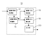
図1は、本実施例の医用運動解析装置10の構成図である。この医用運動解析装置10では、臓器の一つである心臓を解析対象物とする。
【0020】
図1に示すように、医用運動解析装置10は、解析対象物の運動情報を得る運動情報取得部12と、得られた運動情報の時系列データを記憶する運動情報記憶部14と、運動情報の時系列データから運動方向の主要成分方向を推定する運動方向推定部16と、推定された運動方向を主軸とした運動成分値を算出する運動成分算出部18と、算出された運動成分値を出力または表示する出力部20とで構成される。
【0021】
これら各部12から20の機能は、コンピュータに記憶されたプログラムによって実現できる。
【0022】
以下に医用運動解析装置10の処理の流れに沿って説明する。
【0023】
まず、超音波診断装置、MRI、CT等の別の手段によって得られた心臓の動きを撮影した時系列画像を取得する。
【0024】
そして、この時系列画像を解析して、心臓の各部分の運動情報が運動情報取得部12に入力される。ここで心臓の各部分の運動情報とは、各部分における位置座標や速度データ等の時系列データである。
【0025】
時系列の画像から、解析対象物の各点を追跡する手法としては、例えば輝度勾配からオプティカルフローを算出する手法や、パターンマッチングによる追跡法がある。
【0026】
パターンマッチングでは、ある時刻における画像において、追跡点付近の画像をテンプレート画像として取得し、他の時刻における画像について、テンプレート画像に最も似たパターンを持つ位置を追跡点として検出する。似たパターンの評価は、例えば相関や差分等を用いる方法がある。
【0027】
このような手法を用いて、解析対象物の各部分の位置座標を得ることができ、位置座標を時間微分することで速度を得ることができる。
【0028】
以下、本実施例では、各部分の運動情報が2次元の速度データである場合について説明する。速度データは、心臓の各部位各点におけるx方向成分値、y方向成分値である。
【0029】
入力された速度データv=(vx ,vy )は、運動情報記憶部14に順次記憶される。ここで、vx ,vy はそれぞれ、x軸方向、y軸方向の速度成分である。
【0030】
次に、運動方向推定部16では、速度データの時系列データから主要な運動方向の推定を行う。運動方向の推定は、例えば主成分分析を用いる。今、時刻tにおける速度をvt =(vx t ,vy t ) と表す。
【0031】
【数1】

【数2】
【数3】
【0032】
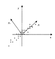
運動方向推定を概念的に図示したものが図2である。
【0033】
図2において、各時刻における速度がプロットで表されている。主成分分析により、速度のばらつきの最も大きい方向が主成分p1 として算出される。つまり、心臓の収縮/拡張運動のように主要な運動成分が収縮/拡張方向である場合には、主成分p1 としてこの収縮/拡張方向が算出されることになる。
【0034】
そして、この主成分p1 の方向が、心臓の収縮/拡張方向を示す解析座標系の主軸となる。
【0035】
次に、主成分分析で求まった解析座標に基づいて、心臓の各部位各点におけるx方向成分値、y方向成分値の速度データを変換する。すなわち、心臓の各部位各点における速度ベクトル方向の運動成分Vk が、下記の式を用いて運動成分算出部18で計算される。
【0036】
【数4】
【0037】
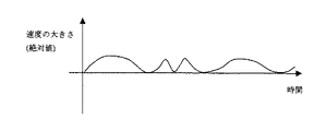
また、心臓の収縮/拡張方向に注目することで、診断上意味のある正負の符号の付いた速度の大きさを算出することが可能となる。従来のx軸方向成分、y軸推定成分で表された速度では、診断上意味のある動き方向が不明なため、意味ある符号付けはできず、速度の大きさは絶対値で表すか(図3参照)、または、仮定された収縮中心へ向かう方向の成分を算出するしかなかった。しかし本実施例によると、診断上意味のある動き方向が速度データ自身から算出されるため、この軸方向に関して正負の符号が付いた速度の大きさを得ることが可能となる(図4参照)。つまり、収縮方向の速度であるのか、拡張方向の速度であるのかを区別することが可能となる。
【0038】
また、主軸方向以外の方向の速度成分に対する意味付けも可能となる。例えば、主軸方向を収縮/拡張方向とした場合、他方の軸方向は回転方向と意味付けることも可能である。
【0039】
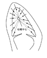
最後に出力部20では、主成分方向及びその他方向の方向ベクトルと、主成分方向及びその他方向の速度成分の時系列データが出力される。図示されないディスプレイーやプリンター等の別手段において、速度データのグラフ表示や画像への重畳表示等を行うことが可能である。また、画像上に図5に示すように主成分方向を明示すると、運動状態及び出力される速度データの理解の助けとなる。
【0040】
なお、図6に示すように、付加的な機能として、心臓壁の複数部分の速度データについての複数の主成分方向から、最小二乗法等により収縮中心の推定を行うことも可能である。
【0041】
(第2の実施例)
次に本発明の第2の実施例について図7から図12に基づいて説明する。
【0042】
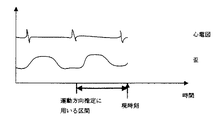
本実施例の医用運動解析装置100は、運動情報として速度データと心筋の歪データが取得される場合であり、主要な運動方向を主軸とする座標系において、歪(伸び縮みの度合い)を求める例である。また本実施例では、運動方向算出に用いる時系列速度データの時間区間を、心拍情報から算出する。
【0043】
本実施例の医用運動解析装置100の構成図を図7に示す。
【0044】
図7に示すように、医用運動解析装置100は、心臓の各部分における速度データと歪データを得る運動情報取得部112と、得られた時系列速度データを記憶する速度データ記憶部114と、歪データを記憶する歪データ記憶部116と、時系列速度データから運動方向の主要成分方向を推定する運動方向推定部118と、推定された運動方向を主軸とした速度成分値を算出する速度成分算出部120と、運動方向推定部118で推定された主要運動方向を主軸とする座標系に歪データを変換する歪データ変換部122と、変換後の速度成分値及び歪データを出力または表示する出力部124とで構成される。
【0045】
運動情報取得部112では、速度データと歪データが順次入力される。速度データは、心臓の各部位各点におけるx方向成分値、y方向成分値である。歪データは、x方向の伸縮を表すexx、y方向の伸縮を表すeyy、ずれを表すexyといった、歪テンソルの値が心臓各部位各点について入力される。これらの歪データにより、図9に示すような伸縮とずれを表すことができる。速度データは速度データ記憶部114に記憶され、歪データは歪データ記憶部116に記憶される。歪テンソルは、次式である。
【0046】
【数5】
【0047】
具体例で説明すると、心拍数が60であった場合には、1心拍にに要する時間は1秒であるので、過去1秒分の時系列データからの運動の主軸を算出すると良い。あるいは、安定性向上のために過去数心拍分の時系列データを用いても良いし、逆に運動変化への追従性向上のために、半心拍分の時系列データを用いても良い。いずれにしても、心拍情報を基に、使用する時間区間を決定することで、心臓の運動に対する合理的な時間区間を適応的に算出することが可能となる。
【0048】
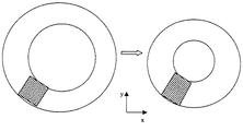
心臓の運動では、心筋の運動方向と心筋厚の変化方向は近いと考えることができる。そこで、運動方向推定部118で推定された主要運動方向を主軸に持つ座標系に、歪データを変換する。推定された主軸と、元のx軸との角度をφとすると、変換後の歪テンソルは次式で計算される。
【0049】
【数6】
【0050】
最後に出力部122では、変換された速度データと歪データが出力される。また、図12のように心筋の部分ごとに心筋厚の歪分布をグラフ化しても良い。このようにすることで、心筋のどの部分が異常であるかを把握しやすい。
【0051】
(変更例)
2つの実施例においては、2次元の速度データを扱う場合について例示したが、3次元の速度データに対しても同様の処理をすることができる。また速度データや歪データだけでなく、歪速度等、他の量に対しても同様の処理をすることができる。
【0052】
【発明の効果】
本発明によれば、臓器の運動方向についての仮定や仮定に基づく手動設定作業無しに、診断上有用な運動情報を提供することが可能となり、診断の高精度化及び効率化に大きく寄与する。
【図面の簡単な説明】
【図1】第1の実施例のの医用運動解析装置の構成図である。
【図2】時系列速度ベクトルの主成分方向の例である。
【図3】絶対値で表示された速度の例である。
【図4】主成分方向成分の正負区別された速度の例である。
【図5】主成分方向の表示例である。
【図6】収縮中心推定の説明図である。
【図7】第2の実施例のの医用運動解析装置の構成図である。
【図8】運動方向推定に用いる区間を説明する図である。
【図9】歪の様子を説明する図である。
【図10】変換前の座標系における歪の説明図である。
【図11】変換後の座標系における歪の説明図である。
【図12】心筋厚歪分布の表示例である。
【符号の説明】
10 医用運動解析装置
12 運動情報取得部
14 運動情報記憶部
16 運動方向推定部
18 運動成分算出部
20 出力部[0001]
BACKGROUND OF THE INVENTION
The present invention relates to a medical motion analysis apparatus that analyzes motion of an organ or the like.
[0002]
[Prior art]
In the diagnosis of heart disease and the like, it is important to accurately measure organ movement. For this reason, a method for acquiring 2D or 3D motion information of organ parts has been proposed so far (Masahide Nishiura et al., “Ultrasonic heart wall dynamic contour extraction method using partial shape constrained contour model”, electronic information Journal of Communications Society (D-II), vol.J83-D-II, no.1, pp.183-190, Jan. 2000), Mikio Umehara and others, IEICE Transactions (D-II), vol.J79-D-II, no.2, pp.286-294, Feb. 1996).
[0003]
The motion information directly obtained by these methods is a change in position and velocity in the x-axis, y-axis, and z-axis directions orthogonal to each other.
[0004]
On the other hand, taking the heart motion as an example, typical motion of the ventricular wall can be divided into motion in the contraction / expansion direction and motion in a direction different from the contraction / expansion direction due to torsion or rotation. . In the diagnosis of heart disease and the like, motion information using the main axis of the contraction / expansion direction, which is the main component of motion, is more suitable for understanding the meaning.
[0005]
From this point of view, conventionally, there are a method of obtaining a motion component in a direction toward a contraction center assumed in advance, and a method of obtaining a motion component in a direction orthogonal to a contour line obtained separately (Japanese Patent Laid-Open No. 10-99334, etc.).
[0006]
[Problems to be solved by the invention]
However, these methods are based on the assumption of the direction of movement, and do not reflect the actual direction of movement.
[0007]
Accordingly, the present invention provides a medical motion analysis apparatus and method that can obtain diagnostically useful motion information without making assumptions about the motion direction of an organ.
[0008]
[Means for Solving the Problems]
According to the first aspect of the present invention, in a medical motion analysis apparatus that analyzes an motion of an analysis object using an organ including a heart as an analysis object, acquisition of motion information for acquiring time-series motion information of each part of the analysis object Means, and a principal component analysis of the time-series motion information to obtain a principal component direction, and a motion meaning that the principal component direction is a principal axis of an analysis coordinate system indicating an expansion / contraction direction of the analysis object A medical motion analysis apparatus comprising: a direction estimation unit; and a motion component calculation unit that calculates a motion component of each part of the analysis object in the estimated analysis coordinate system.
[0009]
The invention according to claim 2 is the medical motion analysis apparatus according to claim 1, wherein the time-series motion information is time-series velocity data of each part of the analysis object.
[0010]
The invention according to claim 3 is the medical motion analysis apparatus according to claim 1, wherein the time-series motion information is time-series position data of each part of the analysis object.
[0011]
In the invention of claim 4, the time-series motion information includes time-series tissue strain data of each part of the analysis object, and the strain for calculating strain data in the analysis coordinate system in each part of the analysis object. The medical motion analysis apparatus according to any one of claims 1 to 3, further comprising data conversion means.
[0012]
The invention according to claim 5 is the medical use according to any one of claims 1 to 3, wherein the time-series motion information includes time-series tissue strain rate data of each part of the analysis object. It is a motion analysis device.
[0013]
The invention according to claim 6 is characterized in that the object to be analyzed is a heart, and includes a contraction center estimation means for estimating a contraction center of the heart from motion components of a plurality of portions of the heart in the analysis coordinate system. The medical motion analysis apparatus according to any one of claims 1 to 5.
[0014]
According to a seventh aspect of the present invention, the analysis object is a heart, and the time-series motion information is time-series motion information within a period calculated from the heartbeat of the heart. It is a medical motion analysis apparatus as described in any one of these.
[0015]
The invention of claim 8 is a medical motion analysis method in which an organ including a heart is used as an analysis object, and a motion of the analysis object is analyzed by a computer, and a time series of each part of the analysis object acquired by the computer The direction of principal component analysis is performed to determine the direction of the principal component, and the direction of the principal component is estimated by the computer to mean that the direction of the principal component of the analysis coordinate system indicating the expansion and contraction direction of the analysis target object. And a motion component calculation step of calculating, by the computer, a motion component of each part of the analysis object in the previously estimated analysis coordinate system.
[0016]
The invention according to claim 9 is a medical motion analysis program for analyzing a motion of an analysis object using an organ including a heart as the analysis object, and the computer stores the time-series motion of each part of the analysis object. A motion information acquisition function for acquiring information and a principal component of the analysis coordinate system in which the principal component analysis is performed on the time series motion information to determine the direction of the principal component, and the direction of the principal component indicates the expansion / contraction direction of the analysis object a motion direction estimation function of implicated as being a medical motion analysis program for realizing the motion component calculation function, the calculating the motion component of each portion of the object to be analyzed in the estimated analyzed coordinate system.
[0017]
According to the present invention, it is possible to provide motion information useful for diagnosis without assuming the motion direction of an organ such as the heart or the stomach or manually setting work based on the assumption.
[0018]
DETAILED DESCRIPTION OF THE INVENTION
(First embodiment)
Hereinafter, a first embodiment of the present invention will be described with reference to FIGS.
[0019]
FIG. 1 is a configuration diagram of a medical
[0020]
As illustrated in FIG. 1, the medical
[0021]
The functions of these
[0022]
Below, it demonstrates along the flow of a process of the medical
[0023]
First, a time-series image obtained by capturing the heart motion obtained by another means such as an ultrasonic diagnostic apparatus, MRI, or CT is acquired.
[0024]
Then, the time series image is analyzed, and the motion information of each part of the heart is input to the motion
[0025]
As a method for tracking each point of the analysis target from a time-series image, for example, there are a method for calculating an optical flow from a luminance gradient and a tracking method by pattern matching.
[0026]
In pattern matching, an image near a tracking point is acquired as a template image in an image at a certain time, and a position having a pattern most similar to the template image is detected as a tracking point in images at other times. For the evaluation of similar patterns, there is a method using, for example, correlation or difference.
[0027]
Using such a method, the position coordinates of each part of the analysis object can be obtained, and the speed can be obtained by differentiating the position coordinates with respect to time.
[0028]
Hereinafter, in the present embodiment, a case where the motion information of each part is two-dimensional velocity data will be described. The velocity data is an x-direction component value and a y-direction component value at each point of each part of the heart.
[0029]
The input speed data v = (v x , v y ) is sequentially stored in the motion
[0030]
Next, the motion
[0031]
[Expression 1]
[Expression 2]
[Equation 3]
[0032]
FIG. 2 conceptually illustrates the motion direction estimation.
[0033]
In FIG. 2, the speed at each time is represented by a plot. The principal component analysis, the largest direction of the variation in speed is calculated as a main component p 1. That is, when the major component of motion such as the heart contraction / expansion motion is contracted / expanded direction will the contraction / expansion direction is calculated as a main component p 1.
[0034]
Then, the direction of the principal component p 1 becomes the analysis coordinate system of the spindle showing the contraction / expansion direction of the heart.
[0035]
Next, the velocity data of the x-direction component value and the y-direction component value at each point of each part of the heart is converted based on the analysis coordinates obtained by the principal component analysis. That is, the motion component V k in the velocity vector direction at each point of each part of the heart is calculated by the motion
[0036]
[Expression 4]
[0037]
Further, by paying attention to the direction of contraction / expansion of the heart, it is possible to calculate the magnitude of the speed with a positive / negative sign that is meaningful in diagnosis. In the speed represented by the conventional x-axis direction component and y-axis estimation component, the meaningful motion direction is unclear for diagnosis, so meaningful signing cannot be performed, and is the magnitude of the speed represented by an absolute value? 3) or a component in a direction toward the assumed contraction center. However, according to the present embodiment, since a meaningful movement direction for diagnosis is calculated from the speed data itself, it is possible to obtain the magnitude of the speed with a positive or negative sign with respect to this axial direction (see FIG. 4). . That is, it is possible to distinguish between the speed in the contraction direction and the speed in the expansion direction.
[0038]
In addition, it is possible to give meaning to velocity components in directions other than the main axis direction. For example, when the main axis direction is the contraction / expansion direction, the other axis direction can also be defined as the rotation direction.
[0039]
Finally, the
[0040]
As shown in FIG. 6, as an additional function, it is also possible to estimate the contraction center by a least square method or the like from a plurality of principal component directions for velocity data of a plurality of portions of the heart wall.
[0041]
(Second embodiment)
Next, a second embodiment of the present invention will be described with reference to FIGS.
[0042]
The medical
[0043]
FIG. 7 shows a configuration diagram of the medical
[0044]
As shown in FIG. 7, the medical
[0045]
In the exercise
[0046]
[Equation 5]
[0047]
To explain with a specific example, when the heart rate is 60, the time required for one heart beat is 1 second, so it is preferable to calculate the main axis of motion from the time series data for the past 1 second. Alternatively, time series data for the past several heartbeats may be used to improve stability, and conversely, time series data for half heartbeats may be used to improve follow-up to movement changes. In any case, by determining the time interval to be used based on the heartbeat information, it is possible to adaptively calculate a reasonable time interval for the heart motion.
[0048]
In heart motion, it can be considered that the direction of motion of the myocardium and the direction of change in myocardial thickness are close. Therefore, the strain data is converted into a coordinate system having the main motion direction estimated by the motion
[0049]
[Formula 6]
[0050]
Finally, the
[0051]
(Example of change)
In the two embodiments, the case where two-dimensional velocity data is handled has been illustrated, but the same processing can be performed for three-dimensional velocity data. The same processing can be performed not only on the speed data and distortion data but also on other quantities such as the distortion speed.
[0052]
【The invention's effect】
ADVANTAGE OF THE INVENTION According to this invention, it becomes possible to provide the exercise | movement information useful for a diagnosis, without the manual setting operation | work based on the assumption about the exercise | movement direction of an organ, and assumption, and it contributes greatly to the highly accurate and efficient diagnosis.
[Brief description of the drawings]
FIG. 1 is a configuration diagram of a medical motion analysis apparatus according to a first embodiment.
FIG. 2 is an example of a principal component direction of a time-series velocity vector.
FIG. 3 is an example of speed displayed as an absolute value.
FIG. 4 is an example of positive and negative speeds of principal component direction components.
FIG. 5 is a display example of the principal component direction.
FIG. 6 is an explanatory diagram of contraction center estimation.
FIG. 7 is a configuration diagram of a medical motion analysis apparatus according to a second embodiment.
FIG. 8 is a diagram illustrating a section used for motion direction estimation.
FIG. 9 is a diagram illustrating a state of distortion.
FIG. 10 is an explanatory diagram of distortion in the coordinate system before conversion.
FIG. 11 is an explanatory diagram of distortion in the coordinate system after conversion.
FIG. 12 is a display example of myocardial thickness strain distribution.
[Explanation of symbols]
DESCRIPTION OF
Claims (9)
前記解析対象物の各部分の時系列運動情報を取得する運動情報取得手段と、
前記時系列運動情報を主成分分析して主成分の方向を求め、この主成分の方向が、前記解析対象物の拡張収縮方向を示す解析座標系の主軸であると意味付けする運動方向推定手段と、
前記推定された解析座標系における前記解析対象物の各部分の運動成分を算出する運動成分算出手段と、
を具備する
ことを特徴とする医用運動解析装置。In a medical motion analysis device that analyzes the motion of an analysis object using an organ including the heart as an analysis object,
Motion information acquisition means for acquiring time-series motion information of each part of the analysis object;
Seeking direction of the principal component and principal component analyzes the time series motion information, the direction of the main component, the motion direction estimation means for implicated as the major axis of the analysis coordinate system showing the extended contraction direction of the object to be analyzed When,
A motion component calculating means for calculating a motion component of each part of the analysis object in the estimated analysis coordinate system;
A medical motion analysis apparatus comprising:
ことを特徴とする請求項1記載の医用運動解析装置。The medical motion analysis apparatus according to claim 1, wherein the time-series motion information is time-series velocity data of each part of the analysis target.
ことを特徴とする請求項1記載の医用運動解析装置。The medical motion analysis apparatus according to claim 1, wherein the time-series motion information is time-series position data of each part of the analysis object.
前記解析対象物の各部分において前記解析座標系での歪データを算出する歪データ変換手段を具備する
ことを特徴とする請求項1から3のうちいずれか一項に記載の医用運動解析装置。The time series motion information includes time series tissue strain data of each part of the analysis object,
The medical motion analysis apparatus according to any one of claims 1 to 3, further comprising strain data conversion means for calculating strain data in the analysis coordinate system in each part of the analysis object.
ことを特徴とする請求項1から3のうちいずれか一項に記載の医用運動解析装置。The medical motion analysis apparatus according to any one of claims 1 to 3, wherein the time series motion information includes time series tissue strain rate data of each part of the analysis target.
前記解析座標系における前記心臓の複数の部分の運動成分から前記心臓の収縮中心を推定する収縮中心推定手段を具備する
ことを特徴とする請求項1から5のうちいずれか一項に記載の医用運動解析装置。The analysis object is a heart;
The medical center according to any one of claims 1 to 5, further comprising contraction center estimation means for estimating a contraction center of the heart from motion components of a plurality of parts of the heart in the analysis coordinate system. Motion analysis device.
前記時系列運動情報が、前記心臓の心拍から算出された期間内の時系列運動情報である
ことを特徴とする請求項1から6のうちいずれか一項に記載の医用運動解析装置。The analysis object is a heart;
The medical motion analysis apparatus according to any one of claims 1 to 6, wherein the time series motion information is time series motion information within a period calculated from a heartbeat of the heart.
前記コンピュータによって取得された前記解析対象物の各部分の時系列運動情報を主成分分析して主成分の方向を求め、この主成分の方向が、前記解析対象物の拡張収縮方向を示す解析座標系の主軸であると前記コンピュータによって意味付けする運動方向推定ステップと、
前記推定された解析座標系における前記解析対象物の各部分の運動成分を前記コンピュータによって算出する運動成分算出ステップと、
を具備する
ことを特徴とする医用運動解析方法。In a medical motion analysis method in which an organ including the heart is an analysis object and the motion of the analysis object is analyzed by a computer,
Principal component analysis is performed on the time-series motion information of each part of the analysis object acquired by the computer to obtain the direction of the principal component, and the analysis coordinates in which the direction of the principal component indicates the expansion / contraction direction of the analysis object A direction of motion estimation step which means by the computer to be the main axis of the system;
A motion component calculating step of calculating, by the computer, a motion component of each part of the analysis object in the estimated analysis coordinate system;
A medical motion analysis method comprising:
前記解析対象物の各部分の時系列運動情報を取得する運動情報取得機能と、
前記時系列運動情報を主成分分析して主成分の方向を求め、この主成分の方向が、前記解析対象物の拡張収縮方向を示す解析座標系の主軸であると意味付けする運動方向推定機能と、
前記推定された解析座標系における前記解析対象物の各部分の運動成分を算出する運動成分算出機能と、
を実現させる医用運動解析プログラム。A medical motion analysis program for analyzing the motion of an analysis object using an organ including the heart as an analysis object.
A motion information acquisition function for acquiring time-series motion information of each part of the analysis object;
Seeking direction of the principal component and principal component analyzes the time series motion information, the direction of this main component, extended a major axis of the analysis coordinate system shown shrinkage direction means attached to the motion direction estimation function of the object to be analyzed When,
A motion component calculation function for calculating a motion component of each part of the analysis object in the estimated analysis coordinate system;
Medical motion analysis program that realizes
Priority Applications (1)
| Application Number | Priority Date | Filing Date | Title |
|---|---|---|---|
| JP2002077315A JP3715580B2 (en) | 2002-03-19 | 2002-03-19 | Medical motion analysis apparatus and method |
Applications Claiming Priority (1)
| Application Number | Priority Date | Filing Date | Title |
|---|---|---|---|
| JP2002077315A JP3715580B2 (en) | 2002-03-19 | 2002-03-19 | Medical motion analysis apparatus and method |
Publications (2)
| Publication Number | Publication Date |
|---|---|
| JP2003265480A JP2003265480A (en) | 2003-09-24 |
| JP3715580B2 true JP3715580B2 (en) | 2005-11-09 |
Family
ID=29205668
Family Applications (1)
| Application Number | Title | Priority Date | Filing Date |
|---|---|---|---|
| JP2002077315A Expired - Fee Related JP3715580B2 (en) | 2002-03-19 | 2002-03-19 | Medical motion analysis apparatus and method |
Country Status (1)
| Country | Link |
|---|---|
| JP (1) | JP3715580B2 (en) |
Families Citing this family (8)
| Publication number | Priority date | Publication date | Assignee | Title |
|---|---|---|---|---|
| JP2006061581A (en) | 2004-08-30 | 2006-03-09 | Toshiba Corp | Medical motion analysis apparatus, medical motion analysis method and medical motion analysis program |
| JP5063216B2 (en) * | 2007-06-27 | 2012-10-31 | 日立アロカメディカル株式会社 | Ultrasonic diagnostic apparatus and processing program |
| WO2009072397A1 (en) | 2007-12-07 | 2009-06-11 | Konica Minolta Medical & Graphic, Inc. | Dynamic imaging system |
| WO2009148041A1 (en) * | 2008-06-03 | 2009-12-10 | 株式会社 日立メディコ | Medical image processing device and method for processing medical image |
| US8208703B2 (en) * | 2008-11-05 | 2012-06-26 | Toshiba Medical Systems Corporation | Medical image analysis apparatus and image analysis control program |
| JP5526401B2 (en) * | 2009-03-31 | 2014-06-18 | 国立大学法人東京農工大学 | Ventricular wall information extraction device |
| CN104156975B (en) * | 2013-05-13 | 2018-04-24 | 东芝医疗系统株式会社 | Medical image analysis apparatus and method and medical imaging devices |
| JP7136588B2 (en) | 2018-05-14 | 2022-09-13 | キヤノンメディカルシステムズ株式会社 | Ultrasound diagnostic device, medical image diagnostic device, medical image processing device and medical image processing program |
-
2002
- 2002-03-19 JP JP2002077315A patent/JP3715580B2/en not_active Expired - Fee Related
Also Published As
| Publication number | Publication date |
|---|---|
| JP2003265480A (en) | 2003-09-24 |
Similar Documents
| Publication | Publication Date | Title |
|---|---|---|
| CN106340015B (en) | A kind of localization method and device of key point | |
| EP2026280B1 (en) | Method and corresponding apparatus for quantitative measurements on sequences of images, particularly ultrasonic images | |
| US6295464B1 (en) | Apparatus and method for dynamic modeling of an object | |
| JP4348383B2 (en) | Device for displaying curved anatomical M-mode of biological structures | |
| US6757423B1 (en) | Methods of processing tagged MRI data indicative of tissue motion including 4-D LV tissue tracking | |
| JP3725442B2 (en) | Medical image diagnostic apparatus and method | |
| JP2006061581A (en) | Medical motion analysis apparatus, medical motion analysis method and medical motion analysis program | |
| Hartkens et al. | Using points and surfaces to improve voxel-based non-rigid registration | |
| US20030171668A1 (en) | Image processing apparatus and ultrasonic diagnosis apparatus | |
| JP5491747B2 (en) | Medical image analysis apparatus and control program for image analysis | |
| JP2003508139A (en) | Non-rigid motion image analysis | |
| McEachen et al. | Multiframe temporal estimation of cardiac nonrigid motion | |
| US20050148844A1 (en) | Biomagnetic measurement apparatus | |
| JP3715580B2 (en) | Medical motion analysis apparatus and method | |
| JP2002140689A (en) | Medical image processor and its method | |
| JP2012061019A (en) | Image processing apparatus, image processing method, and image processing program | |
| Wick et al. | Detection of cardiac quiescence from B-mode echocardiography using a correlation-based frame-to-frame deviation measure | |
| Kerwin et al. | Image processing and analysis in tagged cardiac MRI | |
| JP6690053B2 (en) | Blood flow analysis device, method and program | |
| McLeod et al. | A near-incompressible poly-affine motion model for cardiac function analysis | |
| Duncan et al. | Physical and geometrical modeling for image-based recovery of left ventricular deformation | |
| Foroughi et al. | Elastic registration of 3d ultrasound images | |
| CN114581599A (en) | Method for rapidly acquiring system by ultrasonic three-dimensional structure independent of external positioning equipment | |
| JP4332669B2 (en) | Joint center measuring device | |
| US11457814B2 (en) | Apparatus for determining a disease parameter |
Legal Events
| Date | Code | Title | Description |
|---|---|---|---|
| A131 | Notification of reasons for refusal |
Free format text: JAPANESE INTERMEDIATE CODE: A131 Effective date: 20050322 |
|
| A521 | Request for written amendment filed |
Free format text: JAPANESE INTERMEDIATE CODE: A523 Effective date: 20050519 |
|
| A131 | Notification of reasons for refusal |
Free format text: JAPANESE INTERMEDIATE CODE: A131 Effective date: 20050607 |
|
| A521 | Request for written amendment filed |
Free format text: JAPANESE INTERMEDIATE CODE: A523 Effective date: 20050708 |
|
| A521 | Request for written amendment filed |
Free format text: JAPANESE INTERMEDIATE CODE: A523 Effective date: 20050725 |
|
| TRDD | Decision of grant or rejection written | ||
| A01 | Written decision to grant a patent or to grant a registration (utility model) |
Free format text: JAPANESE INTERMEDIATE CODE: A01 Effective date: 20050816 |
|
| A61 | First payment of annual fees (during grant procedure) |
Free format text: JAPANESE INTERMEDIATE CODE: A61 Effective date: 20050825 |
|
| FPAY | Renewal fee payment (event date is renewal date of database) |
Free format text: PAYMENT UNTIL: 20080902 Year of fee payment: 3 |
|
| FPAY | Renewal fee payment (event date is renewal date of database) |
Free format text: PAYMENT UNTIL: 20090902 Year of fee payment: 4 |
|
| FPAY | Renewal fee payment (event date is renewal date of database) |
Free format text: PAYMENT UNTIL: 20090902 Year of fee payment: 4 |
|
| FPAY | Renewal fee payment (event date is renewal date of database) |
Free format text: PAYMENT UNTIL: 20100902 Year of fee payment: 5 |
|
| FPAY | Renewal fee payment (event date is renewal date of database) |
Free format text: PAYMENT UNTIL: 20100902 Year of fee payment: 5 |
|
| FPAY | Renewal fee payment (event date is renewal date of database) |
Free format text: PAYMENT UNTIL: 20110902 Year of fee payment: 6 |
|
| FPAY | Renewal fee payment (event date is renewal date of database) |
Free format text: PAYMENT UNTIL: 20120902 Year of fee payment: 7 |
|
| FPAY | Renewal fee payment (event date is renewal date of database) |
Free format text: PAYMENT UNTIL: 20120902 Year of fee payment: 7 |
|
| FPAY | Renewal fee payment (event date is renewal date of database) |
Free format text: PAYMENT UNTIL: 20130902 Year of fee payment: 8 |
|
| S111 | Request for change of ownership or part of ownership |
Free format text: JAPANESE INTERMEDIATE CODE: R313117 Free format text: JAPANESE INTERMEDIATE CODE: R313114 |
|
| R350 | Written notification of registration of transfer |
Free format text: JAPANESE INTERMEDIATE CODE: R350 |
|
| LAPS | Cancellation because of no payment of annual fees |