JP3709397B2 - Garbage truck - Google Patents
Garbage truck Download PDFInfo
- Publication number
- JP3709397B2 JP3709397B2 JP2003086143A JP2003086143A JP3709397B2 JP 3709397 B2 JP3709397 B2 JP 3709397B2 JP 2003086143 A JP2003086143 A JP 2003086143A JP 2003086143 A JP2003086143 A JP 2003086143A JP 3709397 B2 JP3709397 B2 JP 3709397B2
- Authority
- JP
- Japan
- Prior art keywords
- hopper
- chassis
- water
- cleaning vehicle
- cleaning
- Prior art date
- Legal status (The legal status is an assumption and is not a legal conclusion. Google has not performed a legal analysis and makes no representation as to the accuracy of the status listed.)
- Expired - Lifetime
Links
Images


Landscapes
- Refuse-Collection Vehicles (AREA)
- Cleaning Of Streets, Tracks, Or Beaches (AREA)
Description
【0001】
【発明の属する技術分野】
本発明は、清掃車に関し、特に透水性舗装路の路面を清掃するのに好適なものである。
【0002】
【従来の技術】
路面といった被洗浄物を洗浄する従来の清掃車は、被洗浄物に散水し、散水された水と共に被洗浄物の塵埃を車台に設けられたホッパに回収する。ホッパは、側部に排出口と排出口を閉じるドアとを有している。ホッパは車台に設けられたシリンダに支持されており、シリンダの駆動によって排出口を有する側部が下方へ傾けられる。この清掃車は、排出口が下方へ傾けられた状態において、上記のドアを開放することによって、ホッパ内に回収された塵埃を排出することができる。
【0003】
【特許文献1】
特願2001−73331号公報
【0004】
【発明が解決しようとする課題】
上記の清掃車のホッパ内では、塵埃が沈殿し、その上部を水が覆うように層をなしている。しかしながら、塵埃を排出するためにホッパを傾けるので、ホッパ内の塵埃と水が排出口から同時に排出される。したがって、この清掃車では、ホッパから塵埃を効率良く排出することができないとい問題点がある。
【0005】
本発明は上記の問題点を解決するためになされたもので、ホッパから効率良く塵埃を排出することができる清掃車を提供することを課題としている。
【0006】
【課題を解決するための手段】
上記課題を解決するため、本発明の清掃車は、車台と、被洗浄物に散水し、被洗浄物に散水した水と共に被洗浄物の塵埃を回収する洗浄ユニットと、洗浄ユニットによって回収される水及び塵埃がダクトを介して収容される回収室と、回収室の底面に設けられた排出口と、排出口を閉じる蓋とを有し、車台に設けられるホッパと、ホッパの底面の車台に対する傾斜を一定に維持して、該ホッパを車台の外方へ移動させる移動手段とを備えることを特徴としている。
【0007】
かかる構成の清掃車によれば、ホッパは、移動手段によって車台に対する傾斜を維持して、車台の外方へ移動される。したがって、ホッパ内に回収された水と塵埃は、塵埃の上部を水が覆う層構造が乱されない。また、ホッパは底面に排出口を有するので、水より先に塵埃を排出口から排出することができる。さらに、ホッパ内に残留している塵埃を回収室に溜められている水によって洗い出すことができる。
【0008】
また、本発明の清掃車において、上記の移動手段は、車台に一端が軸支され、ホッパに他端が軸支されるアームを有する平行リンクと、ホッパを前記車台の外方へ移動させる駆動力を上記のアームに与える駆動部とを有することを特徴としても良い。
【0009】
また、本発明の清掃車において、ホッパは、底面の周縁から連続しており回収室の側を覆う側面を有し、排出口は、上記の底面の周縁より内方に設けられており、上記の底面は、側壁から排出口に向かって下方へ傾斜することを特徴とすることが好適である。
【0010】
かかる構成の清掃車では、ホッパの底面は排出口に向かって下方へ傾斜する形状を有しているので、ホッパに回収された塵埃は排出口からより効率よく排出される。
【0011】
【発明の実施の形態】
本発明の実施形態にかかる清掃車1について添付の図面を参照して説明する。なお、以下の実施形態に関する説明においては、説明の理解を容易にするため、各図面において同一又は相当の部分には同一の符号を附すこととする。
【0012】
図1は、清掃車1の側面図である。以下、本明細書において用いる方向を示す語のうち、「上下」とは、図1に示す状態を基準とする。すなわち、清掃車を基準として路面を下方とする。また、「前後」とは、図1に示す状態を基準とし、清掃車の前進方向を前方とする。
【0013】
清掃車1は、車台2と、車台2の底面に取り付けられた洗浄ユニット4と、車台2に設けられたホッパ6と、ホッパ6を車台2の後部外方へ移動させる移動部8と、洗浄ユニット4に水やエアを供給する種々の装置が収容されているコンテナ10とを備える。
【0014】
洗浄ユニット4は、路面(被洗浄物)に水及びエアを吹き付け、路面に吹き付けた水及びエアと共に、路面の塵埃を回収する。図2(a)は、洗浄ユニット4の側面図である。図2(b)は、洗浄ユニット4の平面図であり、洗浄ユニット4を上方から見て示す図である。洗浄ユニット4は、複数の散水ノズル12と、複数のエアノズル14と、6個の吸引ノズル16と、散水ノズル12、エアノズル14、及び吸引ノズル16を覆い、かつ、路面に向けて開口されたカバー18とを有している。洗浄ユニット4では、複数の散水ノズル12、複数のエアノズル14、6個の吸引ノズル16がそれぞれ、清掃車1の幅方向に配列されている。
【0015】
散水ノズル12は、吸引ノズル16の下方の路面にノズル孔を向けている。散水ノズル12は、清掃車1の幅方向に延びる配管19に接続されており、配管19を介して供給される水を路面(被洗浄物)へ吹き付ける。エアノズル14は、吸引ノズル16の下方の路面にノズル孔を向けている。エアノズル14は、清掃車1の幅方向に延びる配管21に接続されており、配管21に接続された高圧空気吐出用の配管22から供給されるエアを路面にエアを吹き付ける。吸引ノズル16は、路面に向かって広がるコーン形状を呈している。吸引ノズル16は、配管24に接続されており、散水ノズル12から路面に吹き付けられた水、及びエアノズル14から路面に吹き付けられたエアと共に路面の塵埃を吸引して、ホッパ6に回収する。
【0016】
図3は、清掃車1の配管系を概略的に示す図である。散水ノズル12が接続されている配管19には、コンテナ10に収容された水タンク26から配管20を介して水が供給される。配管20には駆動装置28によって駆動されるポンプ30が接続されており、ポンプ30は水タンク26に溜められている水を異物を除去するフィルタ32を介して配管20へ供給する。また、水タンク26は、配管34及びポンプ36を介してホッパ6に接続されている。水タンク26には、ホッパ6の回収室38に回収された水がポンプ36によって吸引されて、供給される。すなわち、散水ノズル12によって路面に吹き付けられた水は吸引ノズル16によって回収され、散水ノズル12が路面に吹き付ける水としてリサイクルされる。
【0017】
エアノズル14には、吸引ノズル16によって吸引されホッパ6の回収室38に回収されるエアが循環されて、供給される。エアノズル14は、配管21と、高圧空気吐出用の配管22と、コンテナ10に収容されたブロア40及び配管42と、配管44とを介してホッパ6に接続されている。ブロア40は、駆動装置46によって駆動され、吸引ノズル16とエアノズル14との間にエアを循環させる。
【0018】
図4は、清掃車1の後方から洗浄ユニット4を見て示す図である。図5は、洗浄ユニット4を車台2と共に示す側面図であり、洗浄ユニット4を支持する支持部50を一部破断して示す図である。洗浄ユニット4には、車台2に対向する面の四隅に支持部50の一端が取り付けられている。支持部50は、洗浄ユニット4を上下方向に移動させるシリンダ51と、下端が洗浄ユニット4に固定されると共にシリンダ51の側周を覆う内筒52と、内筒の側周を覆う外筒53とを有する。シリンダ51の下端は内筒52に固定されており、シリンダ51の上端は外筒53に固定されている。シリンダ51は、清掃車1の車体の浮きに応じて洗浄ユニット4と路面との距離を一定に保つように、洗浄ユニット4を下方へ移動させる。清掃車1では、例えば、水タンク26内の水量の減少に応じて洗浄ユニット4を下方へ移動させるために、駆動装置28の駆動時間を計測するタイマを設けて、タイマによって計測された駆動時間に応じて洗浄ユニット4を下方へ移動させるようにシリンダ51を制御することができる。
【0019】
外筒53の側面には、清掃車1の進行方向に沿って延びる軸を中心に回動可能なローラ54が設けられており、ローラ54は、清掃車1の幅方向に延びるローラガイド55に支持されている。ローラガイド55の一端は、車台2に固定されており、ローラガイド55の他端は、架装フレーム56を介して車台2に固定されたシャーシフレーム57に固定されている。
【0020】
また、外筒53の側面には、清掃車1の幅方向に配列された支持部50を連結するパイプ58と、清掃車1の進行方向に配列された支持部50を連結するパイプ59それぞれの端部が固定されている。パイプ59の長手方向中央には、シリンダ60の一端(ロッドの端部)がブラケット61を介して固定されている。シリンダ60の他端はシャーシフレーム57に固定されている。シリンダ60が清掃車1の幅方向に伸縮してパイプ59に駆動力を与えることによって、ローラ54がローラガイド55に沿って移動する。ローラ54の移動に伴って、支持部50に支持された洗浄ユニット4が清掃車1の幅方向に揺動される。したがって、洗浄ユニット4は、清掃車1の幅方向に揺動されつつ、路面を洗浄することができる。
【0021】
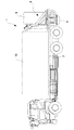
図6は、ホッパ6及び移動部8を拡大して示す側面図である。図7は、清掃車1の前方から見たホッパ6及び移動部8を示す図である。移動部8は、第1アーム70及び第2アーム72によって構成される平行リンクと、ホッパ6を車台2の後方へ移動させる駆動力を与えるシリンダ74とを有する。第1アーム70、第2アーム72、及びシリンダ74は、清掃車1の幅方向に交差するホッパ6の側面に沿うように、それぞれ1対づつ設けられている。
【0022】
第1アーム70の一端は、車台2に固定されたブラケット76に軸支されており、他端がホッパ6に固定されたブラケット78に軸支されている。また、第2アーム72の一端は、ブラケット78と所定の距離を隔てて車台2に固定されたブラケット80に軸支されており、他端がホッパ6に設けられた上述のブラケット78に軸支されている。第1アーム70の他端がブラケット78に軸支されている位置と、第2アーム72の他端がブラケット78に軸支されている位置との距離は、ブラケット76とブラケット80との距離と実質的に等しい。
【0023】
第2アーム72の長手方向の中央部には、一端が車台2に設けられたブラケット82に軸支されたシリンダ74の他端が軸支されている。また、一対の第2アーム72には、その長手方向の中央を連結するブーム84が取り付けられている。かかる構成の移動部8では、シリンダ74を伸張させることによって、第2アーム72がブラケット80を支点に回動し、第2アーム72の回動に伴って第1アーム70がブラケット76を支点に回動する。第1アーム70と第2アーム72とは、平行を保って回動するので、第1アーム70の他端と第2アーム72他端とにブラケット78を介して支持されたホッパ6は、その底面と車台2との傾斜を維持して、車台2の後方へ移動される。
【0024】
ホッパ6の上部側面には配管44が設けられており、配管44の先端にはフランジが設けられている。また、コンテナ10の上部側面から延出している配管42にもフランジが設けられている。ホッパ6が車台2上に配置されているときには、配管42のフランジと配管44のフランジとがパッキンを介して密着することによって、配管42と配管44とが接続される。配管42と配管44とを含む配管系には、ブロア40によってエアが循環されているので、この配管系は負圧が保たれている。したがって、配管42のフランジと配管44のフランジとが強固に密着する。
【0025】
ホッパ6には、回収室38に溜められた塵埃及び水を排出するための排出口90がその底面100の中央に設けられている。ホッパ6の回収室38の底部を構成する底面100は、ホッパ6の側面から排出口90に向かって下方へ傾斜している。また、ホッパ6には、排出口90の一縁を軸にして回動可能な蓋92が設けられており、蓋92は排出口90を閉じている。蓋92には、アーム94の一端が軸支されており、アーム94の他端はホッパ6の下部側面に軸支されたリンク96に軸支されている。リンク96には、一端がホッパ6の側面に軸支されているシリンダ98の他端が軸支されている。
【0026】
シリンダ98が伸張されると、リンク96が下方へ回動され、リンク96の下方への回動に伴ってアーム94が蓋92を上方へ回動させる。したがって、ホッパ6が車台2に配置されているときに、シリンダ98を伸張することによって蓋92が排出口90を閉じることができる。一方、シリンダ98が縮められて、リンク96が上方へ回動され、リンク96の上方への回動に伴ってアーム94が蓋92を下方へ回動させる。したがって、ホッパ6が車台2の後方に配置されているときに、シリンダ98を縮めることによって、蓋92が排出口90を開放することができる。排出口90が解放されることによって、回収室38に溜められた塵埃及び水が排出口90から排出され、例えば塵埃を回収するための搬送車に、排出口90から排出される塵埃が移される。
【0027】
以下、本実施形態にかかる清掃車1の作用を説明する。ホッパ6の回収室38では、沈殿している塵埃を上部から水が覆うように塵埃及び水が層を形成している。清掃車1の移動部8は、ホッパ6の底面の車台2に対する傾斜を維持しつつ、ホッパ6を車台2の後方へ移動させることができるので、上記の層構造を崩すことなく、ホッパ6を車台2の後方へ移動させることができる。
【0028】
車台2の後方へホッパ6を移動させた後、蓋92を開けて排出口90を解放すると、回収室38の底部に沈殿している塵埃が回収室38に回収された水より先に排出口90から排出され、その後に水が排出される。したがって、回収室38に溜められた水の圧力によって塵埃を排出することができ、塵埃が排出された後、回収室38に回収されている水によって回収室38に残留している塵埃を排出口90から洗い出すことができる。このように清掃車1では、ホッパ6に回収された塵埃を効率良く排出口90から排出することができる。
【0029】
また、ホッパ6の底面100は、その中央に設けられた排出口90に向かい下方へ傾斜する形状を有しており、ホッパ6に回収された塵埃が排出され易い形状とされている。
【0030】
なお、本発明は上記した実施形態に限定されるものではなく、種々の変形態様を構成することができる。例えば、移動部8は平行リンクを有する機構に限定されるものではない。例えば、ホッパ6を車台2の後方へ移動させるレールを車台2に設けて、このレールに沿ってホッパ6を車台2の後方へ移動させても良い。
【0031】
【発明の効果】
本発明によれば、ホッパから効率良く塵埃を排出することができる清掃車が提供される。したがって、路面といった被洗浄物を洗浄する作業が軽減される。
【図面の簡単な説明】
【図1】図1は、実施形態にかかる清掃車の側面図である。
【図2】図2(a)は、洗浄ユニットの側面図である。図2(b)は、洗浄ユニットの平面図であり、洗浄ユニットを上方から見て示す図である。
【図3】図3は、実施形態にかかる清掃車の配管系を概略的に示す図である。
【図4】図4は、実施形態にかかる清掃車の後方から洗浄ユニットを見て示す図である。
【図5】図5は、洗浄ユニットを車台と共に示す側面図であり、洗浄ユニットを支持する支持部を一部破断して示す図である。
【図6】図6は、ホッパ及び移動部を拡大して示す側面図である。
【図7】図7は、実施形態にかかる清掃車の前方から見たホッパ及び移動部を示す図である。
【符号の説明】
1…清掃車、2…車台、4…洗浄ユニット、6…ホッパ、8…移動部、10…コンテナ、12…散水ノズル、14…エアノズル、16…吸引ノズル、26…水タンク、90…排出口、100…底面(ホッパ)。[0001]
BACKGROUND OF THE INVENTION
The present invention relates to a cleaning vehicle, and is particularly suitable for cleaning a road surface of a permeable pavement.
[0002]
[Prior art]
A conventional cleaning vehicle that cleans an object to be cleaned such as a road surface sprays water on the object to be cleaned, and collects dust of the object to be cleaned together with the sprinkled water in a hopper provided on the chassis. The hopper has a discharge port and a door for closing the discharge port on the side. The hopper is supported by a cylinder provided in the chassis, and the side portion having the discharge port is tilted downward by driving the cylinder. This cleaning vehicle can discharge the dust collected in the hopper by opening the door in a state where the discharge port is inclined downward.
[0003]
[Patent Document 1]
Japanese Patent Application No. 2001-73331
[Problems to be solved by the invention]
In the hopper of the above-mentioned cleaning vehicle, dust is settled, and a layer is formed so that the upper part is covered with water. However, since the hopper is tilted to discharge dust, the dust and water in the hopper are discharged simultaneously from the discharge port. Therefore, this cleaning vehicle has a problem that dust cannot be efficiently discharged from the hopper.
[0005]
The present invention has been made to solve the above problems, and an object of the present invention is to provide a cleaning vehicle capable of efficiently discharging dust from a hopper.
[0006]
[Means for Solving the Problems]
In order to solve the above problems, a cleaning vehicle of the present invention is recovered by a chassis, a cleaning unit that sprays water on the object to be cleaned, and collects dust on the object to be cleaned together with water sprinkled on the object to be cleaned, and the cleaning unit. A recovery chamber in which water and dust are accommodated via a duct, a discharge port provided in the bottom surface of the recovery chamber, and a lid for closing the discharge port, a hopper provided in the chassis, and a chassis on the bottom surface of the hopper And a moving means for moving the hopper outward of the chassis while maintaining a constant inclination.
[0007]
According to the cleaning vehicle having such a configuration, the hopper is moved to the outside of the chassis while maintaining the inclination with respect to the chassis by the moving means. Therefore, the water and dust collected in the hopper do not disturb the layer structure in which the water covers the upper part of the dust. Further, since the hopper has a discharge port on the bottom surface, dust can be discharged from the discharge port before water. Furthermore, dust remaining in the hopper can be washed out with water stored in the collection chamber.
[0008]
Further, in the cleaning vehicle of the present invention, the moving means includes a parallel link having an arm whose one end is pivotally supported by the chassis and the other end pivotally supported by the hopper, and a drive for moving the hopper outward of the chassis. A driving unit that applies force to the arm may be provided.
[0009]
Further, in the cleaning vehicle of the present invention, the hopper is continuous from the periphery of the bottom surface and has a side surface that covers the collection chamber side, and the discharge port is provided inward from the periphery of the bottom surface, It is preferable that the bottom surface of the head be inclined downward from the side wall toward the discharge port.
[0010]
In the cleaning vehicle having such a configuration, since the bottom surface of the hopper has a shape inclined downward toward the discharge port, the dust collected by the hopper is discharged more efficiently from the discharge port.
[0011]
DETAILED DESCRIPTION OF THE INVENTION
A cleaning vehicle 1 according to an embodiment of the present invention will be described with reference to the accompanying drawings. In the following description of the embodiments, the same or equivalent parts are denoted by the same reference numerals in the drawings in order to facilitate understanding of the description.
[0012]
FIG. 1 is a side view of the cleaning vehicle 1. Hereinafter, among the terms indicating directions used in this specification, “up and down” is based on the state shown in FIG. That is, the road surface is set downward with respect to the cleaning vehicle. Further, “front and rear” is based on the state shown in FIG.
[0013]
The cleaning vehicle 1 includes a
[0014]
The
[0015]
The watering
[0016]
FIG. 3 is a diagram schematically showing a piping system of the cleaning vehicle 1. Water is supplied from the
[0017]
Air that is sucked by the
[0018]
FIG. 4 is a view showing the
[0019]
A
[0020]
In addition, on the side surface of the
[0021]
FIG. 6 is an enlarged side view showing the
[0022]
One end of the
[0023]
At the center of the
[0024]
A
[0025]
The
[0026]
When the
[0027]
Hereinafter, the effect | action of the cleaning vehicle 1 concerning this embodiment is demonstrated. In the
[0028]
After the
[0029]
Further, the
[0030]
In addition, this invention is not limited to above-described embodiment, A various deformation | transformation aspect can be comprised. For example, the moving
[0031]
【The invention's effect】
ADVANTAGE OF THE INVENTION According to this invention, the cleaning vehicle which can discharge | emit dust efficiently from a hopper is provided. Therefore, the work of cleaning the object to be cleaned such as the road surface is reduced.
[Brief description of the drawings]
FIG. 1 is a side view of a cleaning vehicle according to an embodiment.
FIG. 2 (a) is a side view of a cleaning unit. FIG. 2B is a plan view of the cleaning unit, and shows the cleaning unit as viewed from above.
FIG. 3 is a diagram schematically illustrating a piping system of the cleaning vehicle according to the embodiment.
FIG. 4 is a diagram illustrating a cleaning unit as viewed from the rear of the cleaning vehicle according to the embodiment.
FIG. 5 is a side view showing the cleaning unit together with the chassis, and is a view partially showing a support part supporting the cleaning unit.
FIG. 6 is an enlarged side view showing a hopper and a moving part.
FIG. 7 is a diagram illustrating a hopper and a moving unit viewed from the front of the cleaning vehicle according to the embodiment.
[Explanation of symbols]
DESCRIPTION OF SYMBOLS 1 ... Cleaning truck, 2 ... Chassis, 4 ... Cleaning unit, 6 ... Hopper, 8 ... Moving part, 10 ... Container, 12 ... Water nozzle, 14 ... Air nozzle, 16 ... Suction nozzle, 26 ... Water tank, 90 ... Discharge port , 100 ... bottom surface (hopper).
Claims (3)
被洗浄物に散水し、該被洗浄物に散水した水と共に該被洗浄物の塵埃を回収する洗浄ユニットと、
前記洗浄ユニットによって回収される水及び塵埃がダクトを介して収容される回収室と、前記回収室の底面に設けられた排出口と、該排出口を閉じる蓋とを有し、前記車台に設けられるホッパと、
前記ホッパの底面の前記車台に対する傾斜を一定に維持して、該ホッパを前記車台の外方へ移動させる移動手段と
を備える清掃車。The chassis,
A cleaning unit that sprays water on the object to be cleaned and collects the dust of the object to be cleaned together with water sprinkled on the object to be cleaned;
A recovery chamber in which water and dust recovered by the cleaning unit are accommodated via a duct; A hopper,
A cleaning vehicle comprising: moving means for moving the hopper to the outside of the chassis while maintaining a constant inclination of the bottom surface of the hopper with respect to the chassis.
前記車台に一端が軸支され、前記ホッパに他端が軸支されるアームを有する平行リンクと、
前記ホッパを前記車台の外方へ移動させる駆動力を前記アームに与える駆動部と
を有することを特徴とする請求項1に記載の清掃車。The moving means is
A parallel link having an arm pivotally supported at one end by the chassis and pivotally supported at the other end by the hopper;
The cleaning vehicle according to claim 1, further comprising: a driving unit that applies a driving force to the arm to move the hopper outward of the chassis.
前記底面の周縁から連続しており、前記回収室の側を覆う側面を有し、
前記排出口は、前記底面の周縁より内方に設けられており、
前記底面は、前記側壁から前記排出口に向かって下方へ傾斜する
ことを特徴とする請求項1または2に記載の清掃車。The hopper
It is continuous from the periphery of the bottom surface, and has a side surface that covers the collection chamber side,
The discharge port is provided inward from the peripheral edge of the bottom surface,
The cleaning vehicle according to claim 1, wherein the bottom surface is inclined downward from the side wall toward the discharge port.
Priority Applications (1)
| Application Number | Priority Date | Filing Date | Title |
|---|---|---|---|
| JP2003086143A JP3709397B2 (en) | 2003-03-26 | 2003-03-26 | Garbage truck |
Applications Claiming Priority (1)
| Application Number | Priority Date | Filing Date | Title |
|---|---|---|---|
| JP2003086143A JP3709397B2 (en) | 2003-03-26 | 2003-03-26 | Garbage truck |
Publications (2)
| Publication Number | Publication Date |
|---|---|
| JP2004293131A JP2004293131A (en) | 2004-10-21 |
| JP3709397B2 true JP3709397B2 (en) | 2005-10-26 |
Family
ID=33400886
Family Applications (1)
| Application Number | Title | Priority Date | Filing Date |
|---|---|---|---|
| JP2003086143A Expired - Lifetime JP3709397B2 (en) | 2003-03-26 | 2003-03-26 | Garbage truck |
Country Status (1)
| Country | Link |
|---|---|
| JP (1) | JP3709397B2 (en) |
Families Citing this family (3)
| Publication number | Priority date | Publication date | Assignee | Title |
|---|---|---|---|---|
| ES2306071T3 (en) * | 2005-10-07 | 2008-11-01 | Dulevo International S.P.A. | CLEANING UNIT OF STREETS AND SIMILAR. |
| DE102012103381A1 (en) * | 2012-04-18 | 2013-10-24 | Rodinia Technologies Ltd. | Device for cleaning wall or floor surfaces |
| CN110258410B (en) * | 2019-06-06 | 2021-05-07 | 长沙中联重科环境产业有限公司 | Garbage storage device of cleaning vehicle and sidewalk cleaning vehicle |
-
2003
- 2003-03-26 JP JP2003086143A patent/JP3709397B2/en not_active Expired - Lifetime
Also Published As
| Publication number | Publication date |
|---|---|
| JP2004293131A (en) | 2004-10-21 |
Similar Documents
| Publication | Publication Date | Title |
|---|---|---|
| EP1887918B1 (en) | Floor sweeping and scrubbing machine | |
| US7086118B2 (en) | Street sweeper with vacuumized dust control | |
| JPH06154142A (en) | Directly throwing forward type sweeper | |
| EP3345526B1 (en) | Floor scrubber dry sweep apparatus | |
| KR100959401B1 (en) | Vacuum cleaning vehicle having highpressure sprinkler for removing road pollutions | |
| WO2012003727A1 (en) | Road washing and sweeping vehicle | |
| CN109351710A (en) | Cleaning equipment for solar panel | |
| CN110258409A (en) | Pavement sweeper | |
| JP2000303421A (en) | Road surface cleaning truck | |
| KR102118684B1 (en) | Road tunnel cleaning vehicle | |
| CN109454084A (en) | Solar panel intelligence cleaning equipment | |
| JP3709397B2 (en) | Garbage truck | |
| JP2620552B2 (en) | Road vacuum cleaner to collect garbage | |
| JP3635323B2 (en) | Chemical spray car | |
| JP2000175563A (en) | Sulky type machine for cleaning surface of lawn | |
| JP3709478B2 (en) | Suction collection device for granules, etc. | |
| JPH0971915A (en) | Road face and medial strip thereof and dust cart for curb | |
| CN216712878U (en) | Road cleaning equipment | |
| CN216663962U (en) | Rolling brush device for road cleaning equipment and road cleaning equipment | |
| CN218622030U (en) | Road sweeper box and road sweeper | |
| CN216663968U (en) | A suction device and road cleaning equipment for road cleaning equipment | |
| CN114164788A (en) | Road cleaning equipment | |
| JPS644040B2 (en) | ||
| JP2000139216A (en) | Riding lawn cleaning machine | |
| JPH06218341A (en) | Container cleaning device |
Legal Events
| Date | Code | Title | Description |
|---|---|---|---|
| A977 | Report on retrieval |
Free format text: JAPANESE INTERMEDIATE CODE: A971007 Effective date: 20050325 |
|
| A131 | Notification of reasons for refusal |
Free format text: JAPANESE INTERMEDIATE CODE: A131 Effective date: 20050404 |
|
| A521 | Request for written amendment filed |
Free format text: JAPANESE INTERMEDIATE CODE: A523 Effective date: 20050518 |
|
| TRDD | Decision of grant or rejection written | ||
| A01 | Written decision to grant a patent or to grant a registration (utility model) |
Free format text: JAPANESE INTERMEDIATE CODE: A01 Effective date: 20050726 |
|
| A61 | First payment of annual fees (during grant procedure) |
Free format text: JAPANESE INTERMEDIATE CODE: A61 Effective date: 20050808 |
|
| R150 | Certificate of patent or registration of utility model |
Ref document number: 3709397 Country of ref document: JP Free format text: JAPANESE INTERMEDIATE CODE: R150 Free format text: JAPANESE INTERMEDIATE CODE: R150 |
|
| FPAY | Renewal fee payment (event date is renewal date of database) |
Free format text: PAYMENT UNTIL: 20080812 Year of fee payment: 3 |
|
| FPAY | Renewal fee payment (event date is renewal date of database) |
Free format text: PAYMENT UNTIL: 20090812 Year of fee payment: 4 |
|
| R250 | Receipt of annual fees |
Free format text: JAPANESE INTERMEDIATE CODE: R250 |
|
| FPAY | Renewal fee payment (event date is renewal date of database) |
Free format text: PAYMENT UNTIL: 20090812 Year of fee payment: 4 |
|
| FPAY | Renewal fee payment (event date is renewal date of database) |
Free format text: PAYMENT UNTIL: 20100812 Year of fee payment: 5 |
|
| R250 | Receipt of annual fees |
Free format text: JAPANESE INTERMEDIATE CODE: R250 |
|
| FPAY | Renewal fee payment (event date is renewal date of database) |
Free format text: PAYMENT UNTIL: 20100812 Year of fee payment: 5 |
|
| FPAY | Renewal fee payment (event date is renewal date of database) |
Free format text: PAYMENT UNTIL: 20110812 Year of fee payment: 6 |
|
| R250 | Receipt of annual fees |
Free format text: JAPANESE INTERMEDIATE CODE: R250 |
|
| FPAY | Renewal fee payment (event date is renewal date of database) |
Free format text: PAYMENT UNTIL: 20120812 Year of fee payment: 7 |
|
| R250 | Receipt of annual fees |
Free format text: JAPANESE INTERMEDIATE CODE: R250 |
|
| S111 | Request for change of ownership or part of ownership |
Free format text: JAPANESE INTERMEDIATE CODE: R313115 |
|
| FPAY | Renewal fee payment (event date is renewal date of database) |
Free format text: PAYMENT UNTIL: 20120812 Year of fee payment: 7 |
|
| R350 | Written notification of registration of transfer |
Free format text: JAPANESE INTERMEDIATE CODE: R350 |
|
| S533 | Written request for registration of change of name |
Free format text: JAPANESE INTERMEDIATE CODE: R313533 |
|
| FPAY | Renewal fee payment (event date is renewal date of database) |
Free format text: PAYMENT UNTIL: 20120812 Year of fee payment: 7 |
|
| R350 | Written notification of registration of transfer |
Free format text: JAPANESE INTERMEDIATE CODE: R350 |
|
| FPAY | Renewal fee payment (event date is renewal date of database) |
Free format text: PAYMENT UNTIL: 20130812 Year of fee payment: 8 |
|
| R250 | Receipt of annual fees |
Free format text: JAPANESE INTERMEDIATE CODE: R250 |
|
| R250 | Receipt of annual fees |
Free format text: JAPANESE INTERMEDIATE CODE: R250 |
|
| R250 | Receipt of annual fees |
Free format text: JAPANESE INTERMEDIATE CODE: R250 |
|
| R250 | Receipt of annual fees |
Free format text: JAPANESE INTERMEDIATE CODE: R250 |
|
| S111 | Request for change of ownership or part of ownership |
Free format text: JAPANESE INTERMEDIATE CODE: R313117 |
|
| R360 | Written notification for declining of transfer of rights |
Free format text: JAPANESE INTERMEDIATE CODE: R360 |
|
| R360 | Written notification for declining of transfer of rights |
Free format text: JAPANESE INTERMEDIATE CODE: R360 |
|
| R371 | Transfer withdrawn |
Free format text: JAPANESE INTERMEDIATE CODE: R371 |
|
| S111 | Request for change of ownership or part of ownership |
Free format text: JAPANESE INTERMEDIATE CODE: R313117 |
|
| R350 | Written notification of registration of transfer |
Free format text: JAPANESE INTERMEDIATE CODE: R350 |
|
| R250 | Receipt of annual fees |
Free format text: JAPANESE INTERMEDIATE CODE: R250 |
|
| R250 | Receipt of annual fees |
Free format text: JAPANESE INTERMEDIATE CODE: R250 |
|
| R250 | Receipt of annual fees |
Free format text: JAPANESE INTERMEDIATE CODE: R250 |
|
| R250 | Receipt of annual fees |
Free format text: JAPANESE INTERMEDIATE CODE: R250 |
|
| R250 | Receipt of annual fees |
Free format text: JAPANESE INTERMEDIATE CODE: R250 |
|
| R250 | Receipt of annual fees |
Free format text: JAPANESE INTERMEDIATE CODE: R250 |
|
| R250 | Receipt of annual fees |
Free format text: JAPANESE INTERMEDIATE CODE: R250 |
|
| EXPY | Cancellation because of completion of term |