JP3709155B2 - Bag body for bag-in-box and bag-in-box - Google Patents
Bag body for bag-in-box and bag-in-box Download PDFInfo
- Publication number
- JP3709155B2 JP3709155B2 JP2001245400A JP2001245400A JP3709155B2 JP 3709155 B2 JP3709155 B2 JP 3709155B2 JP 2001245400 A JP2001245400 A JP 2001245400A JP 2001245400 A JP2001245400 A JP 2001245400A JP 3709155 B2 JP3709155 B2 JP 3709155B2
- Authority
- JP
- Japan
- Prior art keywords
- bag
- box
- seal portion
- bag body
- seal
- Prior art date
- Legal status (The legal status is an assumption and is not a legal conclusion. Google has not performed a legal analysis and makes no representation as to the accuracy of the status listed.)
- Expired - Lifetime
Links
Images


Landscapes
- Bag Frames (AREA)
- Packages (AREA)
Description
【0001】
【発明の属する技術分野】
本発明は、例えば、食品産業、車産業、トイレタリー産業等の各種分野において液体製品(飲料、カーオイル、洗剤等)を貯蔵、運搬するために利用されるバッグインボックス用袋体とバッグインボックスに関する。
【0002】
さらに詳しくはバッグインボックス用の内袋であって耐衝撃性、内容物の使いきり性および内容物の充填時や外箱からの取り出し後における自立性に優れたバッグインボックス用袋体に関するものであると共に、国際規格のパレット上に無駄なスペースを生じないように隙間なく並べることができ、2段以上に積み上げても充分な安定性と強度を有し、しかもコンパクトで取扱いが容易なバッグインボックスに用いられる内袋に関するものである。
【0003】
また、本発明は、内容物を取り出す際の使い勝手性と使いきり性の改善を図ったバッグインボックスに関するものでもある。
【0004】
【従来の技術】
近年、ミネラルウォーター等の飲料や工業用薬品などの種々の液体の輸送・保管には使い捨てタイプのいわゆるワンウェイ容器であるバッグインボックスが広く用いられている。
【0005】
このバッグインボックスは、内装としてプラスチックフィルムをシール加工して得た平袋や溶融プラスチックをブロー成形して得た一体成形品のようなプラスチック製の折り畳み可能な袋または容器を用い、この内装にダンボール箱等の外箱を外装したものであり、内容液体に対する耐水性、耐薬品性、ガスバリア性等を内装のプラスチック製袋体または容器に受け持たせる一方、輸送・保管上必要な剛性は外装に受け持たせるように構成されている。このように構成されるバッグインボックスは、従来のガラス瓶やブリキ缶等に比べ回収が不要なので省力化・経費節減に役立つとともに、折り畳み可能なので空容器の輸送・保管が容易で流通コストの低減が図れるなどの利点を有している。
【0006】
バッグインボックス用の内袋としては、たとえば図12に示すような袋本体1の上部に注出口12を有する合成樹脂製の平袋501が用いられている。そして図13に示すように、この平袋501は内容物である液体が充填された後、外箱41内に収納され、封入される。
【0007】
しかし、このような平袋型の内袋は外箱の内部形状に対する追従性が悪いので、外箱内へ収納した場合に外箱と内袋の間に無駄な空間42が生じ易く、内袋の隅部4は外箱の内部形状に追従するために折れ曲がってしまい、また、隅部以外の部分にも折れ目や皺が出来やすい。そして、外箱と内袋の間に無駄な空間42が生じると、内袋は外箱内部で動きやすいので、バッグインボックスに落下などの大きい衝撃が加えられた場合に内袋が破裂しやすく、振動などの小さい衝撃が加えられた場合にも内袋がこすれて傷付き破れやすい。また、内袋の一部、特に隅部4が折れ曲がると、その折れ曲がった部分に残液が溜まるので(いわゆる「宙水」)、内容物を最後まで使い切ることが困難である。特にバッグインボックスの場合には比較的内容量が大きいので、上記折れ曲がった部分に溜まる残液の量も多く、残液の排出性をいかに向上させるかが重要である。
【0008】
さらに、平袋型の内袋は自立性を有しないので、バッグインボックスの製造過程において該内袋に液体を充填し、その後、外箱内に収納するに際し、内袋の取扱いが不便である。また、内袋に自立性がないと、たとえば水気が多い濡れた場所でダンボール箱が外装されたバッグインボックスを使用する場合等のように、使用環境に応じて外箱を取り除き内袋だけの状態で使用したい場合においても、取扱いが不便である。
【0009】
一方、バッグインボックスの把持を容易にし使い勝手をよくすると共に、保管運搬時等にコンパクトに積み上げるために、バッグインボックスは立方体形状とするのが望ましい。かかる観点から、比較的需要の多い20リットル前後の内容量を有するバッグインボックスは、一辺が約300mmの立方体とされている。しかし、近年、運搬や保管のためにさまざまな物品を乗せるパレットの寸法について、国際規格が1100mm×1100mm(縦×横)と定められ、今後、この国際規格品がパレットの主流になると共に、パレットを取り扱う流通部門等の各施設でもこの国際規格品に合わせた規格や仕様を採用していくことが予想される。そして、一辺が300mm前後の立方体形状を有するバッグインボックスを国際規格のパレット上に配列する場合には、一段につき縦3列×横3列の合計9個しか積むことができず無駄なスペースが多く残ってしまうという問題がある。また、立方体のバッグインボックスではパレット上に棒積みされることになるので、積載時や運搬時の安定性に欠ける。
【0010】
ところで、バッグインボックスの排液性や使い勝手性に対する外箱の影響も無視できない。バッグインボックスから内容物を取り出す際には、例えば、外箱を両手で持ち、その底部の縁を台の上に支え、外箱から突出した注出口(スパウト)から流れ出る内容物を適当な容器に移しとるなどの操作を行っている。ここで、バッグインボックスの内袋が平袋の場合には、その注出口(スパウト)は通常、外箱の開口部に固定されているので、注出口の周囲の袋本体に折れ目や皺が多数形成され、更にそれらが重なり合ってる。注出口周辺のこの折れ目や皺は、排液を困難にする原因となるのは言うまでもなく、排液の脈動を引き起こし、液ダレの原因になる。また、外箱の開口部から突出する注出口は、外箱に固定されている上、短く、ホース状となっていないので、注出口を手で握って内容物の流出方向を制御することができず、やはり液ダレで周囲を汚す原因になる。
【0011】
一方、バッグインボックスの内袋が一体成形品の場合には、内袋が外箱の内部形状に近い形をとっており、その注出口は外箱の開口部に固定されておらず、しかも注出口の周囲の袋本体はロート型となっているので、使いきり時において残液が注出口に集まり易い。また、注出口が外箱の開口部に固定されていないことから、ある程度の自由度があり、内容物の流出方向を制御することも少しは可能である。しかしながら、一体成形品の内袋は、透明性が悪いので使いきり時の残液量を確認しにくく、また厚く堅く、しかも注出口の長さも短いので、注出口に若干の自由度はあるものの、平袋の場合と同様、注出口を手で握って内容物の流出方向を制御することは困難である。
【0012】
【発明が解決しようとする課題】
本発明は上記実情に鑑みて成し遂げられたものであり、その第一の目的は、耐衝撃性、内容物の使いきり性および内容物の充填時や外箱からの取り出し後における自立性に優れたバッグインボックス用の内袋を提供することにある。また第二の目的は、国際規格のパレット上に無駄なスペースを生じないように隙間なく並べることができ、しかも立方体のバッグインボックスと比べても積み上げ時の安定性や強度、或いは把持や持ち運びの容易性の点で遜色のないバッグインボックスに用いられる内袋を提供することにある。そして第三の目的は、内容物の流出方向を容易に制御することができ、残液量の視認性がよく、残液量が極めて少ないバッグインボックスを提供することにある。
【0013】
【課題を解決するための手段】
上記課題を解決するために、本発明においては、バッグインボックス用の内袋を、次の様に構成した。
すなわち、接着されない状態で重ね合わされた少なくとも2枚の合成樹脂製フィルムによって形成された対向する一対の平面部および谷折り線を備える2つの側面部を有する4方シールの袋本体の各隅部に、袋本体を一対の平面部が重なり合い且つ重なり合った平面部の間に前記谷折り線を備えた2つの側面部が介在するように折り畳んだ状態下で対向する袋本体の内面同士を、頂部および底部の各シール部と側面シール部とを直線帯状に接着して形成された閉鎖シール部を有する、内容物の充填時には直方体又は立方体に近い形状となるバッグインボックス用袋体であって、その頂部側と底部側に関し、頂部シール部、側面シール部及び閉鎖シール部、又は底部シール部、側面シール部及び閉鎖シール部にて、その両側部分に三角形状のフィン部が形成され、これらフィン部は、2枚の前記平面部が前記側面部と別々にシールされて、それぞれ独立して形成され、各フィン部のうち、少なくとも頂部側のフィン部には、前記平面部と前記側面部の内面同士が部分的乃至断続的に接着され、さらに、部分的乃至断続的に接着されたフィン部は、このバッグインボックス用袋体の前後に対向する頂部シール部、又は、頂部シール部及び底部シール部双方が、少なくとも頂点の位置で接着されるように構成した。
【0014】
上記発明には、いくつかの好適な態様がある。第一に、上記のバッグインボックス用袋体において、袋本体の前側と後ろ側の隅部の対向する頂点同士が接着されているように構成することができる。
【0015】
第二に、上記のバッグインボックス用袋体において、一対の平面部および2つの側面部のそれぞれに少なくとも1つずつ、袋本体の上下方向に延在するように帯状のフィルム片が接着されているかまたは帯状の気体充填層が設けられているように構成することができる。
【0016】
第三に、上記のバッグインボックス用袋体において、袋本体の頂部側または底部側のうちの少なくとも一方に左右一対の吊り下げ部が形成されており、該吊り下げ部は、対向し合う前側と後ろ側の三角形状のフィン部同士を、隅部の頂点の位置で接着すると共に、頂部シール部上または底部シール部上の少なくとも一箇所の位置で接着することによって形成されているように構成することができる。
【0017】
第四に、上記のバッグインボックス用袋体において、少なくとも1つの三角形状のフィン部にパンチ穴が形成されているように構成することができる。
【0018】
第五に、上記のバッグインボックス用袋体において、前記合成樹脂製フィルム中の少なくとも1層が金属箔の層であるように構成することができる。
【0019】
第六に、上記のバッグインボックス用袋体において、(e)頂部シール部と閉鎖シール部とに挟まれた狭角を45〜55°とし、底部シール部と閉鎖シール部とに挟まれた狭角を40〜50°とするように構成することができる。
【0020】
第七に、上記のバッグインボックス用袋体において、(f−1)シール部の幅を除いた実寸法で、上記平面部の横寸法が260〜340mm、上記側面部の横寸法が180〜260mm、および上記平面部と上記側面部の縦寸法が490〜660mmであり、(g)内容物の充填時には直方体となるように構成することができる。
【0021】
第八に、上記のバッグインボックス用袋体において、(f−2)シール部の幅を除いた実寸法で、上記平面部の横寸法が190〜270mm、上記側面部の横寸法が140〜220mm、および上記平面部と上記側面部の縦寸法が330〜600mmであり、(g)内容物の充填時には直方体となるように構成することができる。
【0022】
また、本発明においては、バッグインボックスを、外箱の内部に、注出口を備えた前記いずれかのバッグインボックス用袋体、或いは、注出口を備え且つ合成樹脂製フィルムからなる4方シールの袋体(例えば平袋)が内袋として収納されており、外箱の一面には、内袋の注出口を突出させる際に該注出口の周囲の袋本体を50mm以上引き出すことが可能な径を有する開口部を形成するための開封補助手段が備えられていることを特徴とするバッグインボックスとなるように構成した。
【0023】
そして、好適には、上記バッグインボックスに備えられた開封補助手段を、外箱の一面を、前記開口部の中心点となるべき位置から放射状に引き裂くことができ、開封後には、前記開口部の周囲に扇状の断片が残る開封補助手段とすることができる。また、上記バッグインボックスは、好適には、内袋の容量が5〜25リットルであり、外箱が立方体又は直方体となるように構成することができる。
【0024】
本発明のバッグインボックス用袋体は、次のような作用を奏する。第一に、本発明のバッグインボックス用袋体は、前後の平面部とガセットを有する側面部に囲まれ且つ該平面部と該側面部の側縁部同士がシールされた柱構造をとり、しかも頂部側および底部側の各隅部に、あたかも隅部を斜めに切り取るような直線帯状の閉鎖シール部が設けられているので、内容物である液体を充填すると立方体または直方体に近い形状をとる。したがって、本発明のバッグインボックス用袋体は、立方体または直方体の形状を有する外箱の内部形状に対して追従性が優れ、外箱内にぴったりとおさまり、外箱と内袋の間の無駄な空間が極めて少ないので、内袋が外箱内で動きにくく、衝撃による破裂やこすれによる破れが起こりにくい。
【0025】
第二に、本発明のバッグインボックス用袋体には、各隅部に、袋本体の内部空間から完全に閉鎖されて内容物が入り込めない三角形状のフィン部が形成されている。このため隅部に残液が溜まることはなく、バッグインボックスの残液排出性が向上する。さらに、三角形状のフィン部と一体的に形成された前記の閉鎖シール部は、衝撃に対して応力分散の効果があるので、袋体の耐衝撃性が向上する。
【0026】
第三に、本発明のバッグインボックス用袋体は、内容物である液体を充填すると立方体または直方体に近い形状をとるので、自立性に優れている。したがって、バッグインボックスの製造過程(たとえば内袋へ液体を充填する工程や外箱内へ内袋を収納する工程など)やバッグインボックスの外箱を取り外して内袋だけの状態で使用する場合において、取扱いが容易である。
【0027】
第四に、本発明のバッグインボックス用袋体の平面部および側面部は、接着されない状態で重ね合わされた少なくとも2枚の合成樹脂製フィルムによって形成されているので、外側の合成樹脂製フィルムのみが外箱との摩擦で摩耗し、内側の合成樹脂製フィルムは外側の合成樹脂製フィルムに対する滑りによって摩耗しにくい。したがって、1枚の合成樹脂製フィルムで形成された同じ厚さの平面部および側面部と比べて破れにくい。また、内袋の平面部および側面部が上記のように数枚重ねの合成樹脂製フィルムによって形成されている場合には、1枚の合成樹脂製フィルムで同じ厚さの平面部および側面部を形成した場合と比べて内袋の柔軟性に富んでいるので、該内袋を外箱内に収納する際の取扱いが容易である。
【0028】
第一の好適な態様において、袋本体の前側と後ろ側の隅部の対向する頂点同士を接着した場合には、上記三角形状のフィン部が跳ね上がったり不特定の方向に無秩序に折れ曲がったりしないので、バッグインボックスの製造過程(たとえば内袋へ液体を充填する工程や外箱内へ内袋を収納する工程など)やバッグインボックスの外箱を取り外して内袋だけの状態で使用する場合において、三角形状のフィン部が邪魔にならない。また、三角形状のフィン部の介在によって、外箱の上面や下面に内容物が充填されている部分の袋壁が直接接触しなくなるので、振動等による袋のこすれ、裂け、あるいはピンホールが防止される。
【0029】
第二の好適な態様において、袋本体の各平面部および各側面部のそれぞれに少なくとも1つずつ、袋本体の上下方向に延在するように帯状のフィルム片を接着するかまたは帯状の気体充填層を設けた場合には、内袋の自立性がさらに向上する。上述のように本発明のバッグインボックス用袋体は自立性を有しているが、比較的容量が大きいので液体充填の前後を通じて袋本体の胴部がたるみやすく、自立性が不十分な場合がある。これに対して帯状のフィルム片が接着されているかまたは帯状の気体充填層が設けられている場合には、袋本体の胴部にコシが出る(剛性または曲げ抵抗性が向上する)ので、胴部のたるみが低減され、内袋の自立性がさらに向上する。
【0030】
第三の好適な態様において、対向し合う前側と後ろ側の三角形状のフィン部同士を、隅部の頂点の位置で接着すると共に、頂部シール部上または底部シール部上の少なくとも一箇所の位置で接着することによって、袋の頂部側または底部側のうちの一方または両方に左右一対の吊り下げ部を形成した場合には、フィン部と胴部の間の空間に手や機械ハンドを差し入れて袋体を吊り下げることが可能になる。
【0031】
第四の好適な態様において、袋本体の各隅部にある三角形状のフィン部の少なくとも1つにパンチ穴を形成した場合には、そのパンチ穴にフック等を引っかけることによって袋の自立を補助したり、袋を吊り下げたりできるので、バッグインボックスの製造過程や内袋だけの状態で使用する際の取扱いが容易である。
【0032】
第五の好適な態様において、合成樹脂製フィルムの少なくとも1層を金属箔の層とした場合には、袋体の遮光性が極めて高くなり、また金属箔層の形状保持作用によって袋の自立性が向上する。
【0033】
第六の好適な態様において、頂部シール部と閉鎖シール部とに挟まれた狭角を45〜55°とし、底部シール部と閉鎖シール部とに挟まれた狭角を40〜50°とした場合には、外箱の内部形状に対する内袋の追従性と残液の低減効果とが特に優れている。
【0034】
すなわち、底部シール部と閉鎖シール部とに挟まれた狭角を40〜50°とすることによって、充填時における袋体の底部を立方体または直方体に非常に近い形状とすることができる。また、ちょうど隅部が折れ曲がる位置に沿って閉鎖シール部を設けることができるので、充填空間を最大限に取りながら隅部の残液貯留を充分に阻止することができる。さらに、衝撃に対する応力分散の効果を最大とすることができる。
【0035】
一方、袋体の頂部は、内容物の自重で下方へ引っ張られ、注出口が備えられ、また、開封時に内容物があふれ出さないように若干の未充填空間が残されている。このため、当該袋体の頂部は、底部ほどには上面が平坦化しないで若干尖った形状を取り、頂部の隅部は底部の隅部と比べてより深い位置で折れ曲がりやすい。そこで、頂部においては、頂部シール部と閉鎖シール部とに挟まれた狭角を45〜55°として閉鎖シール部の位置を若干深くすることによって、頂部においても隅部が折れ曲がる位置に沿って閉鎖シール部を設ける。その結果、袋の頂部において、充填空間を最大限に取りながら隅部の残液貯留を充分に阻止することができる。
【0036】
第七の好適な態様において、(f−1)シール部の幅を除いた実寸法で、上記平面部の横寸法を260〜340mm、上記側面部の横寸法を180〜260mm、および上記平面部と上記側面部の縦寸法を490〜660mmとし、(g)内容物の充填時に直方体となるようにした場合には、国際規格のパレットとの相性が極めて良い20リットル前後の容量のバッグインボックスを提供することができる。
【0037】
すなわち、上記寸法の平面部と側面部とを有する本発明の袋体は、20リットル前後の容量を有し、内容物の充填時には平面部の横寸法260〜340mm、側面部の横寸法180〜260mm、高さ230〜480mmのおおむね直方体となる。従って、この袋体を内袋として使用すれば、内容量が20リットル前後で、実質的に上記寸法と同じ寸法を有する直方体のバッグインボックスが得られる。なお、充填時の袋の高さの方が充填前の平面部および側面部の縦寸法と比べて側面部の横寸法分だけ短くなるのは、平面部と側面部の上端と下端が袋体の上面側と下面側に回り込むことによって、充填時形状の上面と底面が形成されるためである。
【0038】
そして、このようにして得られた容量20リットルで直方体形状のバッグインボックスは、1100mm×1100mm(縦×横)のパレット上に、一段当たり縦4列×横3列の合計12個をぴったりと積むことができる。また、バッグインボックスが上記寸法の範囲内であれば、個々のバッグインボックスは幅が薄くなり過ぎたり細長くなり過ぎたりしないので、把持が容易で使い勝手がよく、充分な安定性と強度も保持している。さらに、バッグインボックスが直方体であれば、バッグインボックスを並べる方向を各段ごとに変えて井桁状に積み上げることができるので、積み上げた山全体としても充分な安定性と強度を確保することができる。
【0039】
第八の好適な態様において、(f−2)シール部の幅を除いた実寸法で、上記平面部の横寸法を190〜270mm、上記側面部の横寸法を140〜220mm、および上記平面部と上記側面部の縦寸法を330〜600mmとし、(g)内容物の充填時には直方体となるようにした場合には、国際規格のパレットとの相性が極めて良い10リットル前後の容量のバッグインボックスを提供することができる。
【0040】
すなわち、上記寸法の袋体は、10リットル前後の容量を有し、内容物の充填時には平面部の横寸法190〜270mm、側面部の横寸法140〜220mm、高さ110〜460mmのおおむね直方体となる。従って、この袋体を内袋として使用すれば、内容量が10リットル前後で、実質的に上記寸法と同じ寸法を有する直方体のバッグインボックスが得られる。
【0041】
そして、このようにして得られた容量10リットルで直方体形状のバッグインボックスは、1100mm×1100mm(縦×横)のパレット上に、一段当たり縦5列×横4列の合計20個をぴったりと積むことができる。また、第七の態様と同じく、個々のバッグインボックスは幅が薄くなり過ぎたり細長くなり過ぎたりしないので、把持が容易で使い勝手がよく、充分な安定性と強度も保持している。さらに、バッグインボックスを並べる方向を各段ごとに変えて井桁状に積み上げることができるので、積み上げた山全体としても充分な安定性と強度を確保することができる。
【0042】
一方、本発明のバッグインボックスにおいては、使用時に開封補助手段を使って外箱に開けた開口部から、注出口と共に注出口の周囲の袋本体を50mm以上引き出すことができるので、注出口の周囲がロート型になる。このため、注出口に内容物が集まり易く、排液も円滑である。従って、残液が残りにくく、脈動も少ない。また、注出口が外箱から十分に引き出されているので、注出口を容易に掴むことができ、内容物の流出方向を制御しやすい。しかも、内袋は一体成形品ではなく、薄い合成樹脂製フィルムのシール加工によって形成されたものであり透明性が高いので、残液の視認性が良好である。
【0043】
本発明のバッグインボックスに設ける開封補助手段は、開口部を開ける際に、外箱の開口部の中心点となるべき位置から放射状に外箱を引き裂くことができ、且つ、扇状の引き裂き断片を開口部の周囲に残すことが出来るような開封補助手段とするのが好ましい。この場合、開口部から引き出された注出口および注出口の周囲の袋本体が、開口部の周囲に残された扇状の引き裂き断片によって押さえつけられ、あるいは支持されるので、注出口の位置が安定する。
【0044】
【発明の実施の形態】
次に、本発明の実施の形態を示し、本発明についてさらに具体的に説明する。
【0045】
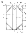
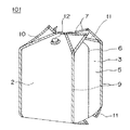
図1は、本発明のバッグインボックス用袋体の一例を折り畳んだ状態を示す正面図である。また図2は、図1の袋体に内容物を充填した状態を示す斜視図である。
【0046】
図1および図2に沿って説明すると、本発明のバッグインボックス用袋体101は、水や油の輸送・保管に用いられる容量20リットルの袋体である。ただし、本発明においては、内容物の種類および容量に特別の制限はない。内容物としては、たとえば飲料水、コーヒー、スープ、ワイン、酒、牛乳、乳飲料等の飲料、醤油、ソース等の風味調味料、カーオイル、洗剤、工業用薬品等の化学製品などが広く該当する。内容物は、固形物入りの液体であってもよいし、粉体等の液体以外の流動体であってもよい。また、容量に関しては、たとえば5リットル程度の家庭用から、20リットル程度の業務用にまで広く適用できる。
【0047】
図2に示したように、内容物を充填した状態の本発明の袋体は、三角形状のフィン部11が存在することを除けば、おおむね立方体または直方体である。なお、袋体101の場合には、おおむね直方体である。
【0048】
袋体101は、袋の前側と後ろ側を構成する対向する一対の平面部2、3および折り襞状に内方に折り込まれた谷折り線6を備えるように形成された2つの側面部5を有し、袋本体の周縁に頂部シール部7、底部シール部8および側面シール部9が存在する4方シールの袋体であり、且つ、袋本体の各隅部4に閉鎖シール部10と三角形状のフィン部11とを有している。
【0049】
各平面部および各側面部は、正方形または長方形であり、袋体101の場合、平面部2、3および側面部5はすべて長方形である。頂部シール部7、底部シール部8、側面シール部9および閉鎖シール部10を形成するための接着は、通常、ヒートシール法によって行われる。なお、袋本体を形成するためのフィルムを折り曲げ成形することによって、頂部シール部7、底部シール部8および側面シール部9の一部を省略することができる。袋体101には、適宜、従来のバッグインボックス用内袋と同様の注出口12を設けてもよい。
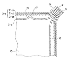
【0050】
図3は、充填された状態の本発明の袋体101の水平方向切断面を模式的に示した図である。図3に示すように、平面部2、3および側面部5は、接着されない状態で重ね合わされた少なくとも2枚の合成樹脂製フィルムによって形成され、緩衝撃型の構造となっている。ここで、「重ね合わされた少なくとも2枚の合成樹脂製フィルムによって形成される」とは、複数の合成樹脂フィルムが分離しているかまたは分離可能な状態で重ね合わされた構造をとっていることを言う。そのような構造としては、例えば、図3に示すような接着されない状態で重ね合わされた構造を例示することができる。また、別の例としては、袋の使用開始後に剥離する程度の接着強度で疑似接着された積層構造を例示することができる。疑似接着されたフィルムは、袋の製造段階においてその取扱いが容易である。
【0051】
図3において前側の平面部2を例にとって説明すると、平面部2は外側フィルム2−aと内側フィルム2−bとから形成され、側面シール部9等の各シール部において上記フィルム2−aと2−bとが接着され、それ以外の未接着部分では両フィルムの間に空間16が存在する。ただし、両フィルムは、側面シール部9等の各シール部以外の部分17において局部的に接着されていてもよい。各フィルムは、2−bのように単層フィルムであってもよいし、2−aのように複合フィルムであってもよい。
【0052】
各合成樹脂製フィルムあるいはフィルム中の各層の材料樹脂や厚さ等は、内容物の性質や袋に要求される強度等の諸条件を考慮して適宜決定されるものであるが、一般的には、外側フィルム2−aまたは外側フィルムの外側層2−a1に関しては、外部環境との関係で要求される強度や耐摩耗性等の性能を重視して決定され、一方、内側フィルム2−bまたは内側フィルムの内側層(2−b中には存在しない。)に関しては、内部環境との関係で要求される耐水性、耐薬品性、ガスバリア性あるいはシール性等の性能を重視して決定される。また、外側フィルム2−aと内側フィルム2−bとの間または外側フィルムの内側層2−a3と内側フィルムの外側層(2−b中には存在しない。)との間の関係では、なるべく両者間の滑りがよくなる組み合わせを選ぶのが好ましい。
【0053】
たとえば、上記の袋体101の平面部2、3および側面部5においては、外側フィルム2−aは複合フィルムであり、その層構成[外側層2−a1/中間層2−a2/内側層2−a3]は、15μmの延伸ナイロン(ON)/20μmのポリエチレン(PE)/60μmの線状低密度ポリエチレン(LLDPE)である。一方、内側フィルム2−bは単層フィルムであり、60μmのLLDPEフィルムである。
【0054】
その他の具体例としては、
(1)外側フィルム[外側から内側に向かって、15μmのポリ塩化ビニリデンコートON層(KコートON)/20μmのPE/60μmのLLDPE]と内側フィルム[60μmのLLDPE]、
(2)外側フィルム[12μmの金属蒸着ポリエチレンテレフタレート層(VMPET)/15μmのON/20μmのPE/60μmのLLDPE]と内側フィルム[60μmのLLDPE]、
(3)外側フィルム[15μmのON/20μmのPE/60μmのLLDPE・ON・LLDPE共押出しフィルム]と内側フィルム[60μmのLLDPE・ON・LLDPE共押出しフィルム]、あるいは、
(4)外側フィルム[15μmのON/20μmのPE/60μmのLLDPE・エチレン−ビニルアルコール共重合体(EVOH)・LLDPE共押出しフィルム]と内側フィルム[60μmのLLDPE・EVAL・LLDPE共押出しフィルム]
(5)外側フィルム[12μmのシリカ蒸着ポリエチレンテレフタレート層/15μmのON/20μmのPE/60μmのLLDPE]と内側フィルム[60μmのLLDPE]
(6)外側フィルム[12μmのアルミナ蒸着ポリエチレンテレフタレート層/15μmのON/20μmのPE/60μmのLLDPE]と内側フィルム[60μmのLLDPE]
などの組み合わせを例示できる。
【0055】
上記の例示において、ONは強度向上に有効であり、KコートON、VMPET、EVOHはバリア性向上に有効である。また(3)は、特に強度を向上させたい場合に好適である。
【0056】
合成樹脂製フィルム中の少なくとも1層は、アルミニウム箔のような金属箔の層であってもよい。金属箔層は、袋体の遮光性を極めて高いものとし、また袋体の形状保持性を高めて自立性の向上に寄与する。従って、外箱の遮光性があまり良くない場合や、内袋を外箱から取り出して使用する場合などに効果的である。
【0057】
袋本体の各隅部4には、充填時の袋体101がなるべく立方体または直方体に近い形状となるようにする共に、各隅部4に三角形状のフィン部11を形成するために、閉鎖シール部10が形成されている。この閉鎖シール部10は、袋本体を、一対の平面部2、3が重なり合い且つ重なり合った両平面部の間に谷折り線6を備えた2つの側面部5が介在するように折り畳んだ状態下、すなわち図1に示す状態下で、対向する袋本体の内面同士を、頂部シール部および底部シール部のうちのいずれかのシール部の任意位置Pから側面シール部の任意位置Qまでに渡って直線帯状に接着することによって形成される。
【0058】
上記と同様に、充填時の袋体101がなるべく立方体または直方体に近い形状となるようにする観点から、任意位置Pは、できるだけ頂部シール部7および底部シール部8と谷折り線6との交点に近いほうが好ましい。このため、任意位置Pは、通常、頂部シール部7および底部シール部8と谷折り線6との交点から±1cmの範囲内、好適には該交点上に設けられる。
【0059】
さらに、やはり上記と同様の観点から、各隅部4に存在する各閉鎖シール部10は、袋本体の右側と左側、前側と後ろ側および頂部側と底部側のそれぞれの位置関係にある閉鎖シール部同士ができるだけ対称的であることが好ましい。
【0060】
充填時の袋体101がなるべく立方体または直方体に近い形状となるようにする観点から、閉鎖シール部10は、三角形状のフィン部11ができるだけ直角二等辺三角形に近い形状となるように形成するのが好ましい。そのためには、頂部シール部および底部シール部のうちのいずれかのシール部と閉鎖シール部に挟まれた狭角m(m1、m2)および側面シール部と閉鎖シール部に挟まれた狭角n(n1、n2)は、通常30〜60°、好適には40〜50°、特に好適にはm=n=45°とする。このような観点から、袋体101の底部側においては、m2=n2=45°を採用している。
【0061】
しかし、袋の頂部側の閉鎖シール部は、底部側の閉鎖シール部よりも若干深い位置に形成するのがさらに好ましい。より具体的には、頂部シール部と閉鎖シール部とに挟まれた狭角m1の下限値を45°以上、好ましくは46°以上、より好ましくは48°以上とし、上限値を55°以下、好ましくは53°以下、より好ましくは52°以下とする。袋の頂部側は、内容物の自重で下方へ引っ張られ、注出口が備えられ、また、開封時に内容物があふれ出さないように若干の未充填空間が残されているので、底部ほどには上面が平坦化しないで若干尖った形状を取り、その結果、頂部の隅部は底部の隅部と比べてより深い位置で折れ曲がりやすい。そこで、頂部側の閉鎖シール部の角度を上記のように調整し、頂部側においても隅部が折れ曲がる位置に沿って閉鎖シール部を形成することによって、充填空間を最大限に取りながら隅部の残液貯留を充分に阻止することができる。このような観点から、袋体101の頂部側においては、m1=50°、n1=40°を採用している。
【0062】
袋本体の各隅部4には、頂部シール部7および底部シール部8のうちのいずれかのシール部、側面シール部9および閉鎖シール部10に囲まれることによって、閉鎖シール部10と一体的に、三角形状のフィン部11が形成されている。この三角形状のフィン部11の内部空間は、閉鎖シール部10によって袋本体の内部空間から完全に閉鎖されているので、袋内に充填された内容物はその中に入り込めない。したがって、袋体101を外箱内に収納する際に、三角形状のフィン部11が形成されている各隅部4が折れ曲がっても、隅部に残液は溜まらず、バッグインボックスの残液排出性が向上する。さらに、三角形状のフィン部と一体的に形成された前記の閉鎖シール部10は、衝撃に対して応力分散の効果があるので、袋体の耐衝撃性が向上する。
【0063】
三角形状のフィン部11において対向する袋本体の内面同士は、図1に示すように接着されていなくてもよいが、閉鎖シール部10の接着部分と連続的に接着されていてもよい。この場合には、フィン部11の内部空間がない状態となる。また、フィン部11の内面同士は、全面的にではなくて部分的乃至断続的に接着されていてもよい。
【0064】
三角形状のフィン部11は、本来的には本発明の袋体の不要部分であり、この部分が跳ね上がったり不特定の方向に折れ曲がったりして、該袋体の取り扱いを繁雑にする。たとえば、バッグインボックスの製造過程(たとえば内袋へ液体を充填する工程や外箱内へ内袋を収納する工程など)やバッグインボックスの外箱を取り外して内袋だけの状態で使用する場合において、三角形状のフィン部11は邪魔になる。このような取扱い上の繁雑さを解消するために、好適には図4に示すように、袋本体の前側と後ろ側の隅部の対向する頂点R同士を接着する。このようにすることによって、三角形状のフィン部11が邪魔にならなくなるだけでなく、三角形状のフィン部11の介在によって外箱の上面や下面に内容物が充填されている部分の袋壁が直接接触しなくなるので、振動等による袋のこすれ、裂け、あるいはピンホールを防止することもできる。
【0065】
頂点R同士を接着するに際しては、頂点R付近をさらに接着してもよい。たとえば、袋本体の前側と後ろ側の対向する頂部シール部7同士または底部シール部8同士を、頂点Rの接着部分と連続的にまたは不連続的に接着してもよい。なお、隅部の頂点同士を接着する場合には袋本体の各シール部を形成するのに用いられる接着装置を流用できる。
【0066】
袋本体の前側と後ろ側の対向する頂部シール部7同士または底部シール部8同士を、頂点Rの接着部分と連続的または不連続的に接着することによって、袋体の頂部側または底部側に左右一対の吊り下げ部を形成してもよい。この吊り下げ部を形成した場合には、フィン部と胴部の間の空間に手や機械ハンドを差し入れて袋体を吊り下げることが可能となるので、袋体の移動や内容物の排出に際して便利である。特に袋体の製造過程においては、機械ハンドによって充填後の重い袋体を持ち上げ、それを外箱に入れることができるので、人員の削減による省力化や、無菌充填システムの導入による環境衛生の向上に有利となる。
【0067】
上記吊り下げ部を形成するために頂点Rの位置の接着部と連続的または不連続的に形成される接着部は、帯状のシール部であってもよいし、円形、楕円形、四角形等のポイントシール部(スポットシール部)であってもよい。
【0068】
フィン部11には、図4に示すようにパンチ穴14を開けてもよい。このパンチ穴14にフックを引っかけることによって、バッグインボックス用袋体の自立を補助したり、吊り下げたりすることができる。従って、製造時において充填や外箱への収納などの各種作業を行う場合や、使用時において外箱から内袋の取り出して内袋だけの状態で使用する場合に便利である。通常は図4に示すように、袋体の頂部側に、前後2枚のフィン部を貫通する左右一対のパンチ穴14を形成する。ただし、パンチ穴14の数と位置は特に制限されず、例えば、袋体の底部側に左右一対のパンチ穴を設けてもよい。
【0069】
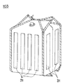
本発明のバッグインボックス用袋体においては、図5および図6に示すように、一対の平面部2、3および2つの側面部5のそれぞれに少なくとも1つずつ、袋本体の上下方向に延在するように帯状のフィルム片31を接着するか(図5)、または、帯状の気体充填層32を設ける(図6)ことによって、ガセット袋の胴部にコシが出すことができる。したがって、ガセット袋の胴部がたるみにくくなり、袋の自立性が向上する。なお、帯状の気体充填層32を設ける場合には、内袋の保温性、断熱性およびクッション性をも向上させることができる。
【0070】
帯状のフィルム片31としては、通常、幅5cm程度のコシのある合成樹脂製フィルムを用い、これをヒートシールなどの任意の接着方法で袋本体の胴部に接着する。コシのある合成樹脂製フィルムとしては、たとえば厚さ60μm以上、好適には60〜100μmのポリエチレンフィルム、ポリプロピレンフィルムを例示することができる。また、粘着性を有する紙ラベルやプラスチックラベルなどを貼付してもよい。
【0071】
帯状のフィルム片31は、数枚重ねされた合成樹脂製フィルムのうちの外側フィルム2−a上に接着してもよいし、内側フィルム2−b上に接着してもよい。また、数枚重ねされた合成樹脂製フィルムのうちの一枚に、フィルム片31の役割を兼ねさせることもできる。たとえば、平面部2、3および側面部5において重なり合う外側フィルム2−aと内側フィルム2−bとを、局部的に且つ袋本体の上下方向に帯状に接着すれば、フィルム片31を別途準備しなくてすむ。
【0072】
図7は、図6に示された気体充填層32付きの平面部2の断面を模式的に示した図である。この図7に沿って説明すると、帯状の気体充填層32は、平面部2の外側表面に、気体充填層32の内面となるべき未接着部分33を残すように、気体不透過性フィルム34を接着積層することによって形成される。数枚重ねされて平面部2を形成する合成樹脂製フィルムのうちの一枚が複合フィルムである場合には、該複合フィルム中の一層が気体不透過性フィルム34を兼ねていてもよい。たとえば、外側フィルムの外側層2−a1は気体不透過性フィルム34を兼ねることができる。気体不透過性フィルム34の接着方法としては、ヒートシールなどの任意の方法を採用することができる。なお、気体充填層1つ分ずつに分割された気体不透過性フィルム34を数列並べて接着してもよい。
【0073】
図6に沿って説明すると、帯状の気体充填層32は、通常、幅5cm程度であり、気体を充填しやすいように気体送入口35が設けられている。また、気体送入口35をすべての気体充填層32にそれぞれ設けるかわりに、気体送入口35を有する気体充填層と有しない気体充填層とを気体送入路36で連絡すれば便利である。内部に充填される気体としては、できるだけ反応性の低いものが好適であり、たとえば空気、不活性ガス、N2ガス、CO2ガスあるいはこれらの混合物が用いられる。また、気体の充填容量は、無充填時のガセット袋と比べて胴部のコシが出る量であればよいが、充分にその目的を達成するためには、通常、最大充填容量の5v/v%以上、好適には7v/v%以上とする。
【0074】
本発明の袋体の寸法は、パレットの国際規格を考慮して決定するのが好ましい。かかる観点から、袋体の容量を20リットル前後(大体15〜25リットル)とする場合には、シール部の幅を除いた実寸法で、平面部の横寸法を260〜340mm、側面部の横寸法を180〜260mm、平面部と側面部の縦寸法を490〜660mmとするのが好ましい。より好ましくは、シール部の幅を除いた実寸法で、平面部の横寸法を280〜320mm、側面部の横寸法を200〜240mm、平面部と側面部の縦寸法を490〜660mmとする。
【0075】
上記寸法を有する袋体は、膨張すると平面部と側面部の上端と下端が袋体の上面側と下面側に回り込むので、充填時の袋の高さの方が充填前の平面部および側面部の縦寸法と比べて側面部の横寸法分だけ短くなる。このため、上記寸法を有する袋体は、充填時には平面部の横寸法260〜340mm、側面部の横寸法180〜260mm、高さ230〜480mmのおおむね直方体となる。従って、この袋体を内袋として使用すれば、上記の膨張時寸法よりも僅かに大きい外寸法を有する直方体のバッグインボックスが得られる。
【0076】
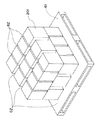
そして、このようにして得られた特定範囲内の寸法を有する20リットル前後のバッグインボックスは、図8に示すように、1100mm×1100mm(縦×横)のパレット61上に、一段当たり縦4列×横3列の合計12個をぴったりと積むことができる。また、バッグインボックスが上記寸法の範囲内であれば、個々のバッグインボックスは幅が薄くなり過ぎたり細長くなり過ぎたりせずコンパクトなので、把持が容易で使い勝手がよく、充分な安定性と強度も保持している。さらに、上記寸法のバッグインボックスは直方体であり、バッグインボックスを並べる方向を、図8に示すように各段ごとに変えて井桁状に積み上げることができるので、積み上げた山全体としても充分な安定性と強度を確保することができる。
【0077】
上記寸法の範囲内で袋の容量を調節したい場合には、平面部と側面部の縦寸法だけを変更することによって容易に調節することができる。例えば、シール部の幅を除いた実寸法で、平面部の横寸法を300mm、側面部の横寸法を220mm、平面部と側面部の縦寸法を575mmとする場合には、膨張時に容量20リットル、平面部の横寸法300mm、側面部の横寸法220mm、高さ334mmとなる袋体が得られ、これを外寸320mm×240mm×390mmの外箱に収納してバッグインボックスとすることができる。
【0078】
これに対して、上記寸法のうち平面部と側面部の縦寸法を491mmに変更し、他の寸法は変えない場合には、膨張時に容量15リットル、平面部の横寸法300mm、側面部の横寸法220mm、高さ250mmとなる袋体が得られ、これを外寸320mm×240mm×300mmの外箱に収納してバッグインボックスとすることができる。
【0079】
さらに、上記寸法のうち平面部と側面部の縦寸法を658mmに変更し、他の寸法は変えない場合には、膨張時に容量25リットル、平面部の横寸法300mm、側面部の横寸法220mm、高さ417mmとなる袋体が得られ、これを外寸320mm×240mm×470mmの外箱に収納してバッグインボックスとすることができる。
【0080】
本発明の袋体の容量を10リットル前後(大体5〜15リットル)とする場合にも、パレットの国際規格を考慮して袋の寸法を決定するのが好ましい。袋体の容量を10リットル前後とする場合には、シール部の幅を除いた実寸法で、平面部の横寸法を190〜270mm、側面部の横寸法を140〜220mm、平面部と側面部の縦寸法を330〜600mmとするのが好ましい。より好ましくは、シール部の幅を除いた実寸法で、平面部の横寸法を210〜250mm、側面部の横寸法を160〜200mm、平面部と側面部の縦寸法を330〜600mmとする。
【0081】
上記寸法を有する袋体は、内容物を充填した時には平面部の横寸法190〜270mm、側面部の横寸法を140〜220mm、高さ110〜460mmのおおむね直方体となるので、この袋を用いることによって、上記の膨張時寸法よりも僅かに大きい外寸法を有する直方体のバッグインボックスが得られる。
【0082】
そして、このようにして得られた特定範囲内の寸法を有する10リットル前後のバッグインボックスは、国際規格のパレット上に、一段当たり縦5列×横4列の合計20個をぴったりと積むことができる。また、コンパクトであり、把持が容易で使い勝手もよく、充分な安定性と強度も保持している。さらに、バッグインボックスを並べる方向を各段ごとに変えて井桁状に積み上げることができるので、積み上げた山全体としても充分な安定性と強度を確保することができる。
【0083】
容量が10リットル前後の場合にも、平面部と側面部の縦寸法だけを変更することによってその容量を容易に調節することができる。例えば、シール部の幅を除いた実寸法で、平面部の横寸法を230mm、側面部の横寸法を180mm、平面部と側面部の縦寸法を464mmとする場合には、膨張時に容量10リットル、平面部の横寸法230mm、側面部の横寸法180mm、高さ266mmとなる袋体が得られ、これを外寸250mm×200mm×320mmの外箱に収納してバッグインボックスとすることができる。
【0084】
これに対して、上記寸法のうち平面部と側面部の縦寸法を331mmに変更し、他の寸法は変えない場合には、膨張時に容量5リットル、平面部の横寸法230mm、側面部の横寸法180mm、高さ133mmとなる袋体が得られ、これを外寸250mm×200mm×190mmの外箱に収納してバッグインボックスとすることができる。
【0085】
さらに、上記寸法のうち平面部と側面部の縦寸法を597mmに変更し、他の寸法は変えない場合には、膨張時に容量15リットル、平面部の横寸法230mm、側面部の横寸法180mm、高さ399mmとなる袋体が得られ、これを外寸250mm×200mm×450mmの外箱に収納してバッグインボックスとすることができる。
【0086】
上述したようなバッグインボックス用袋体を封入する外箱としては、従来から用いられているバッグインボックス用の外箱を用いることができる。バッグインボックス用の外箱として代表的なのは段ボール箱であるが、これを使用すると紙粉が出て内袋の外面に付着したりバッグインボックスの周囲に飛散したりする場合がある。この場合には、プラスチック等の紙粉が出ない材質からなるコンテナーを用いてもよい。
【0087】
プラスチック製のコンテナーのような耐久性のよい外箱は、廃棄せずに回収して再使用することが可能である。再使用型の外箱は折り畳み式とするのが好ましく、また、内袋を外箱から取り出して使用することが比較的多い小容量(10リットル以下)の内袋を封入するのに好適である。折り畳み式コンテナーは遮光性があまり良くない場合があるが、その場合にはアルミニウム箔等の金属箔の層を少なくとも1層有する合成樹脂製フィルムを用いた袋体を内袋とするのが好ましい。
【0088】
外箱の壁面には、内袋の注出口を突出させるための開口部が必要である。そのため、通常は、外箱の壁面にミシン目等の開封補助手段が設けられており、開口部はこの開封補助手段を利用して使用開始時に開けられる。開封補助手段によって形成されるこの開口部は、注出口を突出させる際に、注出口の周囲の袋本体を十分に引き出すことのできる大きさを有しているのが好ましい。
【0089】
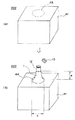
図9に、そのような開封補助手段を備えた外箱と本発明のバッグインボックス用袋体とを組み合わせてなるバッグインボックス202を示す。図9(A)に示すように、バッグインボックスの外箱41には、その一面に注出口を開けるための開封補助手段43が設けられている。この開封補助手段としては、図示したミシン目の他に、例えばティアテープ等を例示できる。図示されていないが、外箱41の内部には本発明のバッグインボックス用袋体が収納されており、その注出口は開口部となるべき開封補助手段43の真下に位置している。注出口は開封後に開口部から引き出す必要があるので、外箱には固定されていない。外箱の材質は特に制限されず、例えば、段ボール紙などを用いることができる。
【0090】
図9(B)に示すように、上記のバッグインボックス202を開封すると、開口部44が形成される。なお、開口部の形状は特に制限されず、例えば、円形、楕円形、四角形、六角形、八角形等の形状を例示できる。開口部44の径dは、キャップ13が付いた注出口12と注出口の周囲の袋本体1とを十分に引き出すことができる大きさを有している。このように開口部から注出口と注出口の周囲の袋本体を十分に引き出すと、注出口の周囲はロート型になり、注出口の周囲の折れ目や皺も少なくなる。したがって残液が注出口に集まりやすく、排液も円滑で脈動が少ない。また、注出口を、まるでホースの先端のように取り扱うことができるので、内容物の流出方向を制御することができる。さらに、注出口付近の残液量も確認しやすい。
【0091】
開口部から引き出す注出口の周囲の袋本体の長さeは、50mm以上とするのが好ましく、特に60mm以上とするのが好ましい。一方、この長さeを一定以上に長くしても、それに見合うだけ便利になるわけではなく、むしろ注出口が邪魔になったり、開口部の径dを極めて大きくする必要が生じる。このため、開口部から引き出された袋本体の長さeは150mm以下とするのが好ましく、特に100mm以下とするのが好ましい。注出口の周囲の袋本体1を50mm以上、好ましくは50〜150mm引き出すことができる径dの具体的な大きさは適宜決定されるべきものではあるが、通常、径を50〜150mmの範囲に設定すれば袋本体を丁度良い長さに引き出すことができる。ここで「径」とは、円形であれば直径をいい、それ以外の形状であれば短径をいう。
【0092】
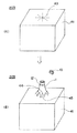
図10(A)〜(B)に示した開封補助手段43によれば、外箱41の壁面を開口部の中心点となるべき位置から放射状に引き裂くことができ、開封後には開口部44の周囲に扇状の断片45が残る。この場合には、開口部から引き出された袋本体1が扇状の断片45によって押さえつけられ、あるいは支持されるので、注出口12の位置が安定する。
【0093】
図11(A)〜(C)に、上述のような開封補助手段43を備えた外箱41と本発明のバッグインボックス用袋体とからなるバッグインボックスの一例を示す。図11(A)に示すように、外箱41の頂部には内側フラップ46、46と外側フラップ47、47とが一対ずつある。内側フラップ46、46は、箱の中に収納された内袋の注出口12と注出口の周囲の袋本体1とを引き出す際の障害とならないように、略円弧状に切り欠かれており、両内側フラップ46、46を閉じた時に略半円形の切り欠き部が形成されるようになっている。また、片方の外側フラップ47には、注出口12が当接する位置に開封補助手段43が設けられている。この内側フラップ46、46と外側フラップ47、47を順次閉じ、次いで、注出口を外箱に固定することなく外箱を封入すれば、図11(B)に示すようなバッグインボックス204が完成する。そして、バッグインボックス204の開封補助部43を利用すれば所定の大きさの開口部44を開けることができ、図11(C)に示すように注出口12と注出口の周囲の袋本体1を引き出すことができる。
【0094】
上記の外箱には、内袋として、平袋のような合成樹脂製フィルムのシール加工によって製造された4方シールの袋体を組み合わせてもよい。このような組合せからなるバッグインボックスの場合にも、開口部から注出口と注出口の周囲の袋本体とを引き出すことによって、残液の低減化、流出時の脈動の防止、流出方向の制御、残液量の視認性向上を図ることができる。なお、4方シールの袋体の周囲に形成されるシール部の一部を、合成樹脂製フィルムを折り曲げ加工することによって省略できる。
【0095】
【実施例】
以下に実験例を示す。
【0096】
実験例1
図1の形状を有する4方シールの袋体を準備した。この袋は、容量が20リットルで、[延伸ナイロン(ON)15μm/ポリエチレン(PE)20μm/線状低密度ポリエチレン(LLDPE)60μm]フィルムと60μmのLLDPEフィルムとからなる平面部と側面部を有する。寸法は、シール幅を除いた実寸法で、平面部の横寸法が300mm、側面部の横寸法が220mm、平面部と側面部の縦寸法が575mmであり、折り込まれたガセットの幅は110mmである。頂部側のフィン部は頂部に沿った辺が110mm、側面部に沿った辺が131mmで、頂部シール部と閉鎖シール部とに囲まれた狭角は50°である。底部側のフィン部は底部に沿った辺及び側面部に沿った辺はどちらも110mmで、底部シール部と閉鎖シール部とに囲まれた狭角は45°である。
【0097】
この袋体を専用のBIB(バッグインボックス)用外箱に収納し、水を満たした後、スパウト部から排水した。排水の初期には箱の両端を手で持ち、スパウト部側の箱の底の縁を水を受ける容器の縁に当てて箱を支えながら排水し、中の水が少なくなるに従い箱を傾けながら排水した。その後、手で箱を水平に保ちながらスパウト部を真下にした状態にして水が完全に切れるのを待った。水がなくなる寸前には、箱を前後左右に軽く振る操作をして水を出易くした。排水終了後、箱の蓋を開けて袋の状態を観察した。
【0098】
その結果、外観的には残液が溜まった袋の折れ曲がり部分は認められなかった。空袋を取り出して逆さにし、ビーカに残液を受けた後、メスシリンダで計量した。
【0099】
上記操作を5回繰り返したところ、残液は実質ゼロ乃至10mlと極めて良好な結果が得られ、この袋体は残液が溜まらない構造になっていることが確認された。
【0100】
なお、測定された残液は、袋の内側に付着した水が集まって形成されたものと推定される。
【0101】
実験例2
図1の形状を有する容量10リットル、及び5リットルの袋体について、実験例1と同様の試験を行ったところ、同様の結果が得られた。
【0102】
ここで用いた容量10リットルの袋体は、実験例1と同じ2枚のフィルムからなる平面部と側面部を有する。寸法は、シール幅を除いた実寸法で、平面部の横寸法が230mm、側面部の横寸法が180mm、平面部と側面部の縦寸法が464mmであり、折り込まれたガセットの幅は90mmである。頂部側のフィン部は頂部に沿った辺が90mm、側面部に沿った辺が108mmで、頂部シール部と閉鎖シール部とに囲まれた狭角は50°である。底部側のフィン部は底部に沿った辺及び側面部に沿った辺はどちらも90mmで、底部シール部と閉鎖シール部とに囲まれた狭角は45°である。
【0103】
また、容量5リットルの袋体は、やはり実験例1と同じ2枚のフィルムからなる平面部と側面部を有する。寸法は、シール幅を除いた実寸法で、平面部の横寸法が230mm、側面部の横寸法が180mm、平面部と側面部の縦寸法が331mmであり、折り込まれたガセットの幅は90mmである。頂部側のフィン部は頂部に沿った辺が90mm、側面部に沿った辺が108mmで、頂部シール部と閉鎖シール部とに囲まれた狭角は50°である。底部側のフィン部は底部に沿った辺及び側面部に沿った辺はどちらも90mmで、底部シール部と閉鎖シール部とに囲まれた狭角は45°である。
【0104】
比較例1
市販の容量20リットルの平パウチ袋を専用のBIB用外箱に収納し、水を満たした後、実験例1と同様に試験を行った。その結果、排水終了付近になっても液切れが悪く、水の流出がだらだらと続いた。液が切れた後、箱の蓋を開けて外観観察したところ、袋の上面の両コーナーと底面の両コーナーは三角形状に不均一に折れ曲がり、そこに水が溜まっていた。
【0105】
同様の操作を5回繰り返して残液を計量したところ、残液量は100乃至200mlとかなり多かった。残液量のばらつきが大きいのは、袋の上面の両コーナーと底面の両コーナーに形成される三角形状に折れ曲がった部分の形状が不規則なために、そこに溜まる残液量が大きく変動するためと推定される。
【0106】
【発明の効果】
以上説明したように、本発明のバッグインボックス用袋体は、柱構造の袋体の各隅部にあたかも該隅部を斜めに切り取るように閉鎖シール部が設けられているので直方体または立方体の形状をとり、しかも数枚重ねの合成樹脂製フィルムで形成されている。したがって、外箱内に収納した状態下において外箱との間に無駄な空間が極めて少なく、外箱内で動きにくく、多重構造であることとも相まって、輸送・保管時等において衝撃や振動によって袋が破裂したり破けたりしにくい。閉鎖シール部は、応力分散によっても耐衝撃性を向上させる。
【0107】
また、本発明のバッグインボックス用袋体は、充填された内容物が各隅部に入り込めない構造となっているので、外箱内に収納する際に各隅部が折れ曲がったとしても隅部に残液は溜まらず、残液排出性が向上する。特に、本発明の袋体において頂部シール部と閉鎖シール部とに挟まれた狭角を45〜55°とし、底部シール部と閉鎖シール部とに挟まれた狭角を40〜50°とする場合には、頂部と底部のどちらにも隅部が折れ曲がる位置に沿って閉鎖シール部を形成できるので、袋内の充填空間を最大限に取りながら隅部の折れ曲がりによって生じる残液貯留を充分に防止することができる。
【0108】
各隅部を袋体の内部空間から遮断することによって形成された三角形状のフィン部は、本来的には不要な部分であるが、これを活用することもできる。すなわち、袋本体の前側と後ろ側の隅部の対向する頂点同士を接着した場合には、三角形状のフィン部が邪魔にならなくなるだけでなく、袋壁のこすれ、裂け、ピンホールが防止される。また、対向する前後のフィン部を一部接着したり、三角形状のフィン部にパンチ穴を開けたりして、これを吊り下げ部として利用することも可能である。
【0109】
さらに、本発明のバッグインボックス用袋体は、内容物である液体を充填すると立方体または直方体に近い形状をとるので、自立性に優れており、その取扱いが容易である。そして、袋本体の胴部に上下方向に延在するように帯状のフィルム片を接着するかまたは帯状の気体充填層を設ける場合には、袋の胴部にコシが出るので、さらに自立性が向上し、取扱いがより容易になる。
【0110】
本発明において、袋体を内容物の充填時に直方体となるようにし、その寸法を、(f−1)シール部の幅を除いた実寸法で、上記平面部の横寸法が260〜340mm、上記側面部の横寸法が180〜260mm、および上記平面部と上記側面部の縦寸法が490〜660mmとなるようにするか、または(f−2)シール部の幅を除いた実寸法で、上記平面部の横寸法が190〜270mm、上記側面部の横寸法が140〜220mm、および上記平面部と上記側面部の縦寸法が330〜600mmとなるようにした場合には、国際規格のパレット上に隙間なく多数積み上げることができ、しかもコンパクトで強度や安定性に優れ、積み上げられた山の安定性と強度にも優れたバッグインボックスが得られる。
【0111】
一方、本発明のバッグインボックスは、本発明のバッグインボックス用袋体または合成樹脂製フィルムからなる4方シールの袋体を内袋とするバッグインボックスの外箱に、注出口の周囲の袋本体を50mm以上引き出すことが可能な開口部を形成できるようにしたので、残液の低減化、流出時の脈動の防止、流出方向の制御、残液量の視認性向上を図ることができる。特に、開口部の周囲に扇状の引き裂き断片を残す場合には、注出口の位置が安定する。
【図面の簡単な説明】
【図1】本発明のバッグインボックス用袋体の一例を折り畳んだ状態を示す正面図である。
【図2】図1の袋体に内容物を充填した状態を示す斜視図である。
【図3】充填された状態の図1の袋体の水平方向切断面を、模式的に示した図である。
【図4】本発明のバッグインボックス用袋体の他の一例に内容物を充填した状態を示す斜視図である。
【図5】本発明のバッグインボックス用袋体の他の一例に内容物を充填した状態を示す斜視図である。
【図6】本発明のバッグインボックス用袋体の他の一例に内容物を充填した状態を示す斜視図である。
【図7】気体充填層付きの平面部の断面を模式的に示した図である。
【図8】本発明のバッグインボックス用袋体を内蔵するバッグインボックスをパレット上に積み上げた状態を示す斜視図である。
【図9】本発明のバッグインボックスの一例を示す説明図である。(A)は開封前の状態を示し、(B)は開封後に注出口を引き出した状態を示す。
【図10】本発明のバッグインボックスの他の一例を示す説明図である。(A)は開封前の状態を示し、(B)は開封後に注出口を引き出した状態を示す。
【図11】本発明のバッグインボックスの他の一例を示す説明図である。(A)はバッグインボックスを組み立てる段階を示し、(B)は完成した状態を示し、(C)は開封後に注出口を引き出した状態を示す。
【図12】従来のバッグインボックス用内袋の一例を示した斜視図である。
【図13】図12の内袋を外箱内に収納した状態を示した図である。
【符号の説明】
1…袋本体
2…前側の平面部
2−a…外側フィルム
2−a1…外側フィルムの外側層
2−a2…外側フィルムの中間層
2−a3…外側フィルムの内側層
2−b…内側フィルム
3…後ろ側の平面部
4…隅部
5…側面部
6…谷折り線
7…頂部シール部
8…底部シール部
9…側面シール部
10…閉鎖シール部
11…三角形状のフィン部
12…注出口
13…キャップ
14…パンチ穴
15…袋の内部空間
16…合成樹脂製フィルム間の空間
17…局部的な接着部分
31…帯状のフィルム片
32…帯状の気体充填層
33…未接着部分
34…気体不透過性フィルム
35…気体送入口
36…気体送入路
41…外箱
42…外箱と内袋の間の空間
43…開封補助手段
44…開口部
45…扇状の断片
46…内側フラップ
47…外側フラップ
61…パレット
62…隙間
101、102、103および104…本発明のバッグインボックス用袋体
201、202、203および204…バッグインボックス
501…従来のバッグインボックス用内袋
P…頂部シール部上および底部シール部上の任意位置
Q…側面シール部上の任意位置
R…隅部の頂点
m…頂部シール部または底部シール部と閉鎖シール部とに挟まれた狭角
m1…頂部シール部と閉鎖シール部とに挟まれた狭角
m2…底部シール部と閉鎖シール部とに挟まれた狭角
n…側面シール部と閉鎖シール部とに挟まれた狭角
n1…側面シール部と頂部側の閉鎖シール部とに挟まれた狭角
n2…側面シール部と底部側の閉鎖シール部とに挟まれた狭角
d…開口部の径
e…引き出された本体の長さ[0001]
BACKGROUND OF THE INVENTION
The present invention relates to a bag-in-box bag and a bag-in-box that are used for storing and transporting liquid products (beverages, car oil, detergents, etc.) in various fields such as the food industry, the car industry, and the toiletry industry. About.
[0002]
More particularly, it relates to an inner bag for a bag-in-box, which is excellent in impact resistance, content exhaustion, and self-supporting when filling the contents or after taking out from the outer box. A bag that can be arranged without gaps on an international standard pallet without gaps, has sufficient stability and strength even when stacked in two or more stages, and is compact and easy to handle The present invention relates to an inner bag used for an in-box.
[0003]
The present invention also relates to a bag-in-box that is improved in usability and usability when taking out contents.
[0004]
[Prior art]
In recent years, bag-in-boxes, which are so-called one-way containers, are widely used for transporting and storing various liquids such as beverages such as mineral water and industrial chemicals.
[0005]
This bag-in-box uses plastic foldable bags or containers such as flat bags obtained by sealing plastic films and integral molded products obtained by blow molding molten plastic. Corrugated cardboard boxes and other outer packaging are used, and water resistance, chemical resistance, gas barrier properties, etc. for the liquid contents are carried by the interior plastic bag or container, while the rigidity required for transportation and storage is exterior. It is comprised so that it may take charge of. The bag-in-box constructed in this way does not require collection compared to conventional glass bottles and tin cans, thus saving labor and reducing costs, and can be folded, making it easy to transport and store empty containers and reduce distribution costs. It has the advantage of being able to plan.
[0006]
As an inner bag for a bag-in-box, for example, a synthetic resin
[0007]
However, since such a flat bag type inner bag has poor followability to the inner shape of the outer box, a
[0008]
Furthermore, since the inner bag of the flat bag type does not have self-supporting property, it is inconvenient to handle the inner bag when filling the inner bag with liquid in the manufacturing process of the bag-in-box and then storing it in the outer box. . Also, if the inner bag is not self-supporting, remove the outer box depending on the usage environment, such as when using a bag-in-box with a corrugated cardboard box in a wet place with a lot of moisture. Even if you want to use it in a state, it is inconvenient to handle.
[0009]
On the other hand, it is desirable that the bag-in-box has a cubic shape so that the bag-in-box can be easily gripped to improve usability and can be stacked compactly during storage and transportation. From this point of view, a bag-in-box having an internal capacity of about 20 liters, which is relatively in demand, is a cube having a side of about 300 mm. However, in recent years, the international standard has been defined as 1100 mm x 1100 mm (vertical x horizontal) for the dimensions of pallets on which various items are placed for transportation and storage. It is expected that each facility such as the distribution department that handles the products will adopt standards and specifications that match this international standard product. And when bag-in-boxes having a cubic shape with sides of around 300 mm are arranged on an international standard pallet, only 9 total of 3 rows x 3 rows can be stacked per stage, resulting in wasted space. There is a problem that many remain. In addition, since the cubic bag-in-box is stacked on a pallet, it lacks stability during loading and transportation.
[0010]
By the way, the influence of the outer box on the drainage and usability of the bag-in-box cannot be ignored. When taking out the contents from the bag-in box, for example, hold the outer box with both hands, support the bottom edge of the outer box on the base, and put the contents flowing out from the spout protruding from the outer box into a suitable container. An operation such as transferring to is performed. Here, when the inner bag of the bag-in-box is a flat bag, the spout is usually fixed to the opening of the outer box, so that the bag body around the spout has folds and wrinkles. Are formed, and they overlap each other. Needless to say, this crease or crease around the spout causes the drainage to pulsate and cause dripping. In addition, the spout protruding from the opening of the outer box is fixed to the outer box and is short and not hose-like, so the outlet direction of the contents can be controlled by grasping the spout by hand. It cannot be done, and it also causes the surroundings to become dirty with liquid dripping.
[0011]
On the other hand, when the inner bag of the bag-in-box is an integrally molded product, the inner bag has a shape close to the inner shape of the outer box, and the spout is not fixed to the opening of the outer box. Since the bag body around the spout is a funnel type, residual liquid tends to collect at the spout when it is used up. Further, since the spout is not fixed to the opening of the outer box, there is a certain degree of freedom, and it is possible to control the outflow direction of the contents a little. However, since the inner bag of the integrally molded product has poor transparency, it is difficult to check the amount of residual liquid when it is used up, it is thick and stiff, and the length of the spout is short, so the spout has some flexibility. As in the case of a flat bag, it is difficult to control the outflow direction of the contents by grasping the spout by hand.
[0012]
[Problems to be solved by the invention]
The present invention has been accomplished in view of the above circumstances, and its first object is excellent in impact resistance, content exhaustion, and self-supporting at the time of filling or taking out from the outer box. It is to provide an inner bag for a bag-in-box. The second purpose is to arrange them without gaps on the international standard pallet so that there is no gap, and the stability and strength when stacked compared to a cubic bag-in-box, or gripping and carrying. It is an object of the present invention to provide an inner bag used for a bag-in-box that is inferior in terms of easiness. A third object is to provide a bag-in-box that can easily control the outflow direction of the contents, has good visibility of the residual liquid amount, and has a very small residual liquid amount.
[0013]
[Means for Solving the Problems]
In order to solve the above-described problems, in the present invention, an inner bag for a bag-in-box is configured as follows.
That is, at each corner of the bag body of a four-side seal having a pair of opposing flat portions and two side portions provided with valley fold lines formed by at least two synthetic resin films laminated in an unbonded state The inner surfaces of the bag bodies facing each other under a state in which the bag body is folded so that the pair of plane portions overlap and the two side surfaces provided with the valley fold line are interposed between the overlapping plane portions, A bag-in-box bag body having a closed seal part formed by adhering each seal part and side seal part at the bottom in a straight band shape, and having a shape close to a rectangular parallelepiped or a cube when filling the contents, With respect to the top side and the bottom side, the top seal part, the side seal part and the closure seal part, or the bottom seal part, the side seal part and the closure seal part, and the triangular These fin portions are formed independently by sealing the two flat portions separately from the side portions, and at least the fin portion on the top side of each fin portion, The inner surfaces of the flat portion and the side portion are partially or intermittently bonded,Furthermore, the fin part bonded partly or intermittently is bonded to the top seal part or the top seal part and the bottom seal part facing the front and rear sides of the bag-in-box bag body at least at the position of the apex. RuIt was configured as follows.
[0014]
The above invention has several preferred embodiments. First, in the bag body for a bag-in-box described above, the apexes facing each other at the front and back corners of the bag main body can be bonded to each other.
[0015]
Secondly, in the bag body for a bag-in-box, a strip-shaped film piece is bonded so as to extend in the vertical direction of the bag body, at least one for each of the pair of plane portions and the two side portions. Or a belt-like gas-filled layer can be provided.
[0016]
Third, in the bag body for a bag in box described above, a pair of left and right hanging portions is formed on at least one of the top side or the bottom side of the bag body, and the hanging portions are opposed to the front side. And the rear triangular fins are bonded to each other at the apex of the corner, and at least one position on the top seal or bottom seal is formed. can do.
[0017]
Fourthly, in the bag body for a bag-in-box described above, it can be configured such that punch holes are formed in at least one triangular fin portion.
[0018]
Fifth, in the bag body for a bag-in-box, at least one layer in the synthetic resin film can be configured to be a metal foil layer.
[0019]
Sixth, in the above bag-in-box bag body, (e) the narrow angle sandwiched between the top seal portion and the closure seal portion is 45 to 55 °, and is sandwiched between the bottom seal portion and the closure seal portion. The narrow angle may be 40 to 50 °.
[0020]
Seventh, in the above bag-in-box bag body, (f-1) the actual dimensions excluding the width of the seal part, the horizontal dimension of the flat part is 260 to 340 mm, and the lateral dimension of the side part is 180 to 260 mm, and the vertical dimension of the plane part and the side part is 490 to 660 mm, and (g) can be configured to be a rectangular parallelepiped when filling the contents.
[0021]
Eighth, in the above bag-in-box bag body, (f-2) the actual dimension excluding the width of the seal part, the horizontal dimension of the flat part is 190 to 270 mm, and the lateral dimension of the side part is 140 to 220 mm, and the vertical dimension of the plane part and the side part is 330 to 600 mm, and (g) can be configured to be a rectangular parallelepiped when filling the contents.
[0022]
In the present invention, the bag-in-box is a four-side seal made of any one of the bag-in-box bags having a spout, or a synthetic resin film. A bag body (for example, a flat bag) is housed as an inner bag, and the bag body around the spout can be pulled out by 50 mm or more when the spout of the inner bag is projected on one surface of the outer box. A bag-in-box is provided, which is provided with opening assisting means for forming an opening having a diameter.
[0023]
And preferably, the opening assisting means provided in the bag-in-box can tear one surface of the outer box radially from the position to be the center point of the opening, and after opening, the opening It can be used as an opening assisting means in which a fan-shaped piece remains around. Moreover, the said bag-in-box can be comprised so that the capacity | capacitance of an inner bag is 5-25 liters and an outer box becomes a cube or a rectangular parallelepiped suitably.
[0024]
The bag body for bag-in-boxes of the present invention has the following effects. First, the bag body for a bag-in-box according to the present invention has a pillar structure that is surrounded by front and rear flat portions and side portions having gussets, and the side portions of the flat portions and the side portions are sealed, In addition, since each of the corners on the top side and the bottom side is provided with a linear band-like closure seal portion that cuts off the corners obliquely, it takes a shape close to a cube or a rectangular parallelepiped when filled with liquid as the contents. . Therefore, the bag body for bag-in-box according to the present invention has excellent followability with respect to the inner shape of the outer box having a cubic or rectangular parallelepiped shape, and fits snugly inside the outer box, and is wasted between the outer box and the inner bag. Because there is very little space, the inner bag is hard to move in the outer box, and it is hard to break due to impact or rubbing.
[0025]
Secondly, in the bag body for bag-in-box according to the present invention, triangular fin portions that are completely closed from the internal space of the bag body and cannot contain the contents are formed at each corner. For this reason, the residual liquid does not accumulate in the corners, and the residual liquid dischargeability of the bag-in-box is improved. Furthermore, since the closure seal portion formed integrally with the triangular fin portion has an effect of stress dispersion for impact, the impact resistance of the bag body is improved.
[0026]
Thirdly, the bag for a box-in-box of the present invention is excellent in independence because it takes a shape close to a cube or a rectangular parallelepiped when filled with the liquid as the contents. Therefore, when the bag-in-box manufacturing process (for example, the process of filling the inner bag with liquid or the process of storing the inner bag in the outer box) or removing the outer box of the bag-in-box and using it in the state of the inner bag only In, it is easy to handle.
[0027]
Fourthly, since the plane part and the side part of the bag body for a bag-in-box of the present invention are formed by at least two synthetic resin films that are not bonded, only the outer synthetic resin film is formed. Wears due to friction with the outer box, and the inner synthetic resin film is less likely to wear due to sliding against the outer synthetic resin film. Therefore, it is hard to tear compared with the plane part and side part of the same thickness formed with one synthetic resin film. In addition, when the flat part and the side part of the inner bag are formed of a plurality of synthetic resin films as described above, the flat part and the side part having the same thickness are formed with one synthetic resin film. Since the inner bag is more flexible than the formed case, the inner bag is easy to handle when stored in the outer box.
[0028]
In the first preferred embodiment, when the opposing vertices of the front and rear corners of the bag body are bonded together, the triangular fins do not jump up or bend in an unspecified direction. In the case of using the bag-in-box manufacturing process (for example, filling the inner bag with liquid or storing the inner bag in the outer box) The triangular fins do not get in the way. In addition, because of the triangular fins, the bag walls where the contents are filled on the upper and lower surfaces of the outer box are not in direct contact with each other, preventing rubbing, tearing, or pinholes due to vibration. Is done.
[0029]
In the second preferred embodiment, at least one of each plane portion and each side portion of the bag body is bonded with a band-shaped film piece so as to extend in the vertical direction of the bag body or is filled with a band-shaped gas When the layer is provided, the self-supporting property of the inner bag is further improved. As described above, the bag body for the bag-in-box according to the present invention has a self-supporting property, but since the capacity is relatively large, the body portion of the bag body tends to sag before and after liquid filling, and the self-supporting property is insufficient. There is. On the other hand, when a strip-shaped film piece is adhered or a strip-shaped gas-filled layer is provided, the body of the bag body becomes stiff (improves rigidity or bending resistance). The sagging of the part is reduced, and the self-supporting property of the inner bag is further improved.
[0030]
In the third preferred embodiment, the front and rear triangular fin portions facing each other are bonded at the apex of the corner, and at least one position on the top seal portion or the bottom seal portion When a pair of left and right hanging parts is formed on one or both of the top side or the bottom side of the bag, the hand or machine hand is inserted into the space between the fin part and the trunk part. The bag body can be suspended.
[0031]
In a fourth preferred embodiment, when a punch hole is formed in at least one of the triangular fin portions at each corner of the bag body, the bag is assisted by hooking a hook or the like to the punch hole. And the bag can be suspended, so that it is easy to handle the bag-in-box in the manufacturing process or when it is used only in the inner bag.
[0032]
In the fifth preferred embodiment, when at least one layer of the synthetic resin film is a metal foil layer, the light shielding property of the bag body becomes extremely high, and the self-supporting property of the bag by the shape holding action of the metal foil layer. Will improve.
[0033]
In a sixth preferred embodiment, the narrow angle sandwiched between the top seal portion and the closure seal portion is 45 to 55 °, and the narrow angle sandwiched between the bottom seal portion and the closure seal portion is 40 to 50 °. In this case, the followability of the inner bag with respect to the internal shape of the outer box and the effect of reducing residual liquid are particularly excellent.
[0034]
That is, by setting the narrow angle sandwiched between the bottom seal portion and the closing seal portion to 40 to 50 °, the bottom portion of the bag body at the time of filling can be shaped very close to a cube or a rectangular parallelepiped. In addition, since the closing seal portion can be provided just along the position where the corner is bent, the remaining liquid storage in the corner can be sufficiently prevented while maximizing the filling space. Furthermore, the effect of stress dispersion on impact can be maximized.
[0035]
On the other hand, the top of the bag is pulled downward by its own weight, is provided with a spout, and a little unfilled space is left so that the contents do not overflow when opened. For this reason, the top portion of the bag body has a slightly sharp shape without being flattened as much as the bottom portion, and the corner portion of the top portion is easily bent at a deeper position than the corner portion of the bottom portion. Therefore, at the top, the narrow angle between the top seal part and the closure seal part is 45 to 55 °, and the position of the closure seal part is slightly deepened, so that the corner also closes along the position where the corner is bent. A seal is provided. As a result, it is possible to sufficiently prevent the remaining liquid from being stored at the corners while maximizing the filling space at the top of the bag.
[0036]
In a seventh preferred embodiment, (f-1) the actual dimensions excluding the width of the seal part, the horizontal dimension of the plane part is 260 to 340 mm, the lateral dimension of the side part is 180 to 260 mm, and the plane part And (g) a bag-in-box with a capacity of around 20 liters, which is extremely compatible with international standard pallets, when the vertical dimension of the side part is 490 to 660 mm and (g) is a rectangular parallelepiped when filling the contents. Can be provided.
[0037]
That is, the bag body of the present invention having the above-described plane portion and side portion has a capacity of about 20 liters, and when filling the contents, the plane portion has a lateral dimension of 260 to 340 mm, and the side portion has a lateral dimension of 180 to It becomes a generally rectangular parallelepiped having a height of 260 mm and a height of 230 to 480 mm. Therefore, when this bag is used as an inner bag, a rectangular bag-in-box having an inner volume of about 20 liters and substantially the same dimensions as the above can be obtained. Note that the height of the bag at the time of filling is shorter by the horizontal dimension of the side part than the vertical dimension of the flat part and side part before filling. This is because the upper surface and the bottom surface of the shape at the time of filling are formed by wrapping around the upper surface side and the lower surface side.
[0038]
The bag-in-box with a capacity of 20 liters obtained in this way has a total of 12 rows of 4 rows x 3 rows per stage on a 1100 mm x 1100 mm (length x width) pallet. Can be stacked. Also, if the bag-in-box is within the above dimensions, the individual bag-in-box will not be too thin or too thin, making it easy to grip, easy to use, and maintaining sufficient stability and strength. are doing. Furthermore, if the bag-in-box is a rectangular parallelepiped, the direction in which the bag-in-box is arranged can be changed in each step and stacked in a cross-girder shape, so that sufficient stability and strength can be ensured even for the entire pile. it can.
[0039]
In an eighth preferred embodiment, (f-2) the actual dimension excluding the width of the seal part, the lateral dimension of the planar part is 190 to 270 mm, the lateral dimension of the side part is 140 to 220 mm, and the planar part And (g) a bag-in-box with a capacity of around 10 liters that is extremely compatible with international standard pallets when the vertical dimension of the side surface is 330 to 600 mm and (g) it is a rectangular parallelepiped when filling the contents. Can be provided.
[0040]
In other words, the bag having the above dimensions has a capacity of about 10 liters, and when filling the contents, the flat part has a horizontal dimension of 190 to 270 mm, the side part has a horizontal dimension of 140 to 220 mm, and a height of 110 to 460 mm. Become. Therefore, if this bag is used as an inner bag, a rectangular bag-in-box having an inner volume of about 10 liters and substantially the same dimensions as described above can be obtained.
[0041]
The bag-in-box having a capacity of 10 liters and a rectangular parallelepiped shape obtained in this way fits a total of 20 rows of 5 rows x 4 rows per stage on a 1100 mm x 1100 mm (length x width) pallet. Can be stacked. Further, as in the seventh aspect, the individual bag-in-boxes do not become too thin or too narrow, so that they are easy to grip and use, and maintain sufficient stability and strength. Furthermore, since the direction in which the bag-in-boxes are arranged can be changed for each step and stacked in a cross-beam shape, sufficient stability and strength can be ensured for the entire stacked mountain.
[0042]
On the other hand, in the bag-in-box of the present invention, the bag body around the spout can be drawn out together with the spout from the opening opened in the outer box by using the opening assisting means at the time of use. The surrounding becomes a funnel type. For this reason, the contents are easily collected at the spout and the drainage is also smooth. Therefore, the remaining liquid is hardly left and pulsation is small. Further, since the spout is sufficiently drawn out from the outer box, the spout can be easily grasped and the outflow direction of the contents can be easily controlled. In addition, the inner bag is not an integrally molded product, but is formed by sealing a thin synthetic resin film and has high transparency, so that the residual liquid is highly visible.
[0043]
The opening assisting means provided in the bag-in-box of the present invention can tear the outer box radially from the position to be the center point of the opening of the outer box when opening the opening, and remove the fan-shaped tear pieces. It is preferable that the opening assisting means can be left around the opening. In this case, the position of the spout is stabilized because the spout drawn out from the opening and the bag body around the spout are pressed down or supported by the fan-shaped tear pieces left around the opening. .
[0044]
DETAILED DESCRIPTION OF THE INVENTION
Next, an embodiment of the present invention will be shown and the present invention will be described more specifically.
[0045]
FIG. 1: is a front view which shows the state which folded up an example of the bag body for bag in boxes of this invention. FIG. 2 is a perspective view showing a state in which the bag body of FIG. 1 is filled with contents.
[0046]
1 and 2, the
[0047]
As shown in FIG. 2, the bag of the present invention filled with the contents is generally a cube or a rectangular parallelepiped except that the
[0048]
The
[0049]
Each plane part and each side part are square or rectangular, and in the case of the
[0050]
FIG. 3 is a diagram schematically showing a horizontal cut surface of the
[0051]
Referring to FIG. 3, the
[0052]
The material resin and thickness of each synthetic resin film or each layer in the film is appropriately determined in consideration of various conditions such as the properties of the contents and the strength required for the bag. The outer film 2-a or the outer layer 2-a1 of the outer film is determined with emphasis on performance such as strength and abrasion resistance required in relation to the external environment, while the inner film 2-b Alternatively, the inner layer of the inner film (not present in 2-b) is determined with an emphasis on performance such as water resistance, chemical resistance, gas barrier properties or sealing properties required in relation to the internal environment. The In addition, the relationship between the outer film 2-a and the inner film 2-b or between the inner layer 2-a3 of the outer film and the outer layer of the inner film (not present in 2-b) is as much as possible. It is preferable to select a combination that improves sliding between the two.
[0053]
For example, in the
[0054]
Other specific examples include
(1) Outer film [from outside to inside, 15 μm polyvinylidene chloride coating ON layer (K coating ON) / 20 μm PE / 60 μm LLDPE] and inner film [60 μm LLDPE],
(2) Outer film [12 μm metal-deposited polyethylene terephthalate layer (VMPET) / 15 μm ON / 20 μm PE / 60 μm LLDPE] and inner film [60 μm LLDPE],
(3) Outer film [15 μm ON / 20 μm PE / 60 μm LLDPE / ON / LLDPE co-extruded film] and inner film [60 μm LLDPE / ON / LLDPE co-extruded film], or
(4) Outer film [15 μm ON / 20 μm PE / 60 μm LLDPE / ethylene-vinyl alcohol copolymer (EVOH) / LLDPE co-extruded film] and inner film [60 μm LLDPE / EVAL / LLDPE co-extruded film]
(5) Outer film [12 μm silica-deposited polyethylene terephthalate layer / 15 μm ON / 20 μm PE / 60 μm LLDPE] and inner film [60 μm LLDPE]
(6) Outer film [12 μm alumina-deposited polyethylene terephthalate layer / 15 μm ON / 20 μm PE / 60 μm LLDPE] and inner film [60 μm LLDPE]
Etc. can be exemplified.
[0055]
In the above example, ON is effective for improving the strength, and K-coat ON, VMPET, and EVOH are effective for improving the barrier property. Further, (3) is suitable particularly when it is desired to improve the strength.
[0056]
At least one layer in the synthetic resin film may be a metal foil layer such as an aluminum foil. The metal foil layer has an extremely high light-shielding property of the bag body and contributes to improvement of the self-supporting property by improving the shape retention of the bag body. Therefore, it is effective when the light shielding property of the outer box is not so good or when the inner bag is taken out from the outer box and used.
[0057]
Each corner 4 of the bag body is provided with a closure seal in order to make the
[0058]
Similarly to the above, from the viewpoint of making the
[0059]
Furthermore, from the same point of view as described above, each closing
[0060]
From the viewpoint of making the
[0061]
However, it is more preferable that the closure seal portion on the top side of the bag is formed at a slightly deeper position than the closure seal portion on the bottom side. More specifically, the lower limit of the narrow angle m1 sandwiched between the top seal part and the closure seal part is 45 ° or more, preferably 46 ° or more, more preferably 48 ° or more, and the upper limit is 55 ° or less. Preferably it is 53 degrees or less, More preferably, it shall be 52 degrees or less. The top side of the bag is pulled downward by the weight of the contents, is provided with a spout, and a little unfilled space is left so that the contents do not overflow when opened. The top surface has a slightly sharp shape without being flattened, and as a result, the top corner tends to bend at a deeper position than the bottom corner. Therefore, the angle of the closing seal portion on the top side is adjusted as described above, and the closing seal portion is formed along the position where the corner bends also on the top side, so that the filling space is maximized while the corner portion is maximized. Residual liquid storage can be sufficiently prevented. From such a viewpoint, m1 = 50 ° and n1 = 40 ° are employed on the top side of the
[0062]
Each corner portion 4 of the bag body is integrated with the
[0063]
The inner surfaces of the bag main bodies facing each other in the
[0064]
The
[0065]
When bonding the vertices R, the vicinity of the vertices R may be further bonded. For example, the
[0066]
By adhering the
[0067]
The adhesive part formed continuously or discontinuously with the adhesive part at the position of the vertex R in order to form the hanging part may be a belt-like seal part, or may be a circle, an ellipse, a quadrangle, etc. It may be a point seal part (spot seal part).
[0068]
As shown in FIG. 4, punch holes 14 may be formed in the
[0069]
In the bag body for a bag-in-box according to the present invention, as shown in FIGS. 5 and 6, at least one each of the pair of
[0070]
As the strip-shaped
[0071]
The strip-shaped
[0072]
FIG. 7 is a view schematically showing a cross section of the
[0073]
Describing along FIG. 6, the belt-like
[0074]
The size of the bag of the present invention is preferably determined in consideration of international standards for pallets. From this point of view, when the capacity of the bag is about 20 liters (generally 15 to 25 liters), the actual dimensions excluding the width of the seal part, the horizontal dimension of the flat part is 260 to 340 mm, and the lateral part is lateral. It is preferable that the dimension is 180 to 260 mm, and the vertical dimension of the plane part and the side part is 490 to 660 mm. More preferably, the horizontal dimension of the flat part is 280 to 320 mm, the horizontal dimension of the side part is 200 to 240 mm, and the vertical dimension of the flat part and the side part is 490 to 660 mm.
[0075]
When the bag body having the above dimensions is inflated, the upper and lower ends of the flat surface portion and the side surface portion wrap around the upper surface side and the lower surface side of the bag body, so that the height of the bag at the time of filling is the flat surface portion and the side surface portion before filling. Compared to the vertical dimension, the horizontal dimension of the side portion is shortened. For this reason, the bag which has the said dimension becomes a rectangular parallelepiped of the horizontal dimension 260-340 mm of a plane part, the horizontal dimension 180-260 mm of a side part, and height 230-480 mm at the time of filling. Therefore, if this bag is used as an inner bag, a rectangular parallelepiped bag-in-box having an outer dimension slightly larger than the above-described inflated dimension can be obtained.
[0076]
Then, the bag-in-box of about 20 liters having dimensions within the specific range obtained in this way is arranged on a
[0077]
When it is desired to adjust the capacity of the bag within the range of the above dimensions, it can be easily adjusted by changing only the vertical dimension of the plane part and the side part. For example, when the horizontal dimension of the flat part is 300 mm, the horizontal dimension of the side part is 220 mm, and the vertical dimension of the flat part and the side part is 575 mm, the actual dimension excluding the width of the seal part is 20 liters during expansion. A bag body having a lateral dimension of 300 mm, a lateral dimension of 220 mm, and a height of 334 mm is obtained, and can be stored in an outer box having an outer dimension of 320 mm × 240 mm × 390 mm to form a bag-in-box. .
[0078]
On the other hand, when the vertical dimension of the flat part and the side part is changed to 491 mm and the other dimensions are not changed, the capacity is 15 liters when expanded, the horizontal dimension of the flat part is 300 mm, and the lateral part is horizontal. A bag body having a size of 220 mm and a height of 250 mm is obtained, and can be accommodated in an outer box having an outer size of 320 mm × 240 mm × 300 mm to form a bag-in-box.
[0079]
Furthermore, when the vertical dimension of the plane part and the side part among the above dimensions is changed to 658 mm and the other dimensions are not changed, the capacity is 25 liters when expanded, the lateral dimension of the plane part is 300 mm, the lateral dimension of the side part is 220 mm, A bag body having a height of 417 mm is obtained, which can be stored in an outer box having an outer dimension of 320 mm × 240 mm × 470 mm to form a bag-in-box.
[0080]
Even when the capacity of the bag of the present invention is about 10 liters (approximately 5 to 15 liters), it is preferable to determine the size of the bag in consideration of the international standard of pallets. When the capacity of the bag body is about 10 liters, the actual dimensions excluding the width of the seal part, the horizontal dimension of the flat part is 190 to 270 mm, the horizontal dimension of the side part is 140 to 220 mm, the flat part and the side part The vertical dimension is preferably 330 to 600 mm. More preferably, the horizontal dimension of the flat part is 210 to 250 mm, the horizontal dimension of the side part is 160 to 200 mm, and the vertical dimension of the flat part and the side part is 330 to 600 mm.
[0081]
When the bag having the above dimensions is filled with the contents, it becomes a generally rectangular parallelepiped having a horizontal dimension of 190 to 270 mm in the plane part, a lateral dimension of the side part of 140 to 220 mm, and a height of 110 to 460 mm. Thus, a rectangular parallelepiped bag-in-box having an outer dimension slightly larger than the above-described inflated dimension is obtained.
[0082]
The bag-in-box of around 10 liters having dimensions within the specific range obtained in this way is to stack a total of 20 rows of 5 rows x 4 rows per stage on an international standard pallet. Can do. In addition, it is compact, easy to grip, easy to use, and maintains sufficient stability and strength. Furthermore, since the direction in which the bag-in-boxes are arranged can be changed for each step and stacked in a cross-beam shape, sufficient stability and strength can be ensured for the entire stacked mountain.
[0083]
Even when the capacity is around 10 liters, the capacity can be easily adjusted by changing only the vertical dimension of the flat surface portion and the side surface portion. For example, if the actual dimensions excluding the width of the seal part, the horizontal dimension of the flat part is 230 mm, the horizontal dimension of the side part is 180 mm, and the vertical dimension of the flat part and the side part is 464 mm, the capacity is 10 liters when expanded. A bag body having a lateral dimension of 230 mm, a lateral dimension of 180 mm, and a height of 266 mm is obtained, and can be stored in an outer box having an outer dimension of 250 mm × 200 mm × 320 mm to form a bag-in-box. .
[0084]
On the other hand, if the vertical dimension of the flat part and the side part is changed to 331 mm and the other dimensions are not changed, the capacity is 5 liters when expanded, the horizontal dimension of the flat part is 230 mm, and the lateral part is horizontal. A bag body having a size of 180 mm and a height of 133 mm is obtained, and can be stored in an outer box having an outer dimension of 250 mm × 200 mm × 190 mm to form a bag-in-box.
[0085]
Furthermore, when the vertical dimension of the plane part and the side part among the above dimensions is changed to 597 mm and the other dimensions are not changed, the capacity is 15 liters when expanded, the lateral dimension of the plane part is 230 mm, the lateral dimension of the side part is 180 mm, A bag body having a height of 399 mm is obtained, which can be stored in an outer box having an outer dimension of 250 mm × 200 mm × 450 mm to form a bag-in-box.
[0086]
Conventionally used outer boxes for bag-in-boxes can be used as outer boxes for enclosing bag-in-box bags as described above. A typical outer box for a bag-in-box is a cardboard box. However, when this is used, paper powder may come out and adhere to the outer surface of the inner bag or may be scattered around the bag-in-box. In this case, a container made of a material that does not produce paper dust such as plastic may be used.
[0087]
A durable outer box such as a plastic container can be recovered and reused without being discarded. The reusable outer box is preferably a foldable type, and is suitable for enclosing a small-capacity (less than 10 liters) inner bag that is often used after being taken out of the outer bag. . The foldable container may not be very light-shielding. In that case, it is preferable to use a bag body made of a synthetic resin film having at least one metal foil layer such as an aluminum foil as the inner bag.
[0088]
An opening for projecting the spout of the inner bag is required on the wall surface of the outer box. For this reason, normally, opening assisting means such as perforations are provided on the wall surface of the outer box, and the opening is opened at the start of use using this opening assisting means. The opening formed by the opening assisting means preferably has a size that can sufficiently draw out the bag body around the spout when the spout is protruded.
[0089]
FIG. 9 shows a bag-in-
[0090]
As shown in FIG. 9B, when the bag-in-
[0091]
The length e of the bag body around the spout drawn out from the opening is preferably 50 mm or more, and particularly preferably 60 mm or more. On the other hand, even if the length e is made longer than a certain value, it is not convenient for the length e. Rather, the spout becomes in the way or the diameter d of the opening needs to be extremely large. For this reason, the length e of the bag body drawn out from the opening is preferably 150 mm or less, particularly preferably 100 mm or less. The specific size of the diameter d that can pull out the
[0092]
According to the
[0093]
11A to 11C show an example of a bag-in box including the
[0094]
The outer box may be combined with a four-side sealed bag produced by sealing a synthetic resin film such as a flat bag as an inner bag. Even in the case of a bag-in-box consisting of such a combination, by pulling out the spout and the bag body around the spout from the opening, it is possible to reduce residual liquid, prevent pulsation during outflow, and control the outflow direction. Further, the visibility of the residual liquid amount can be improved. A part of the seal portion formed around the bag body of the four-side seal can be omitted by bending the synthetic resin film.
[0095]
【Example】
Experimental examples are shown below.
[0096]
Experimental example 1
A four-side sealed bag having the shape of FIG. 1 was prepared. This bag has a capacity of 20 liters, and has a plane part and a side part made of [stretched nylon (ON) 15 μm / polyethylene (PE) 20 μm / linear low density polyethylene (LLDPE) 60 μm] film and 60 μm LLDPE film. . The dimensions are the actual dimensions excluding the seal width. The horizontal dimension of the flat part is 300 mm, the horizontal dimension of the side part is 220 mm, the vertical dimension of the flat part and the side part is 575 mm, and the width of the folded gusset is 110 mm. is there. The fin portion on the top side has a side of 110 mm along the top and a side of 131 mm along the side surface, and the narrow angle surrounded by the top seal portion and the closing seal portion is 50 °. The fin portion on the bottom side has a side along the bottom portion and a side along the side surface portion of 110 mm, and the narrow angle surrounded by the bottom seal portion and the closing seal portion is 45 °.
[0097]
The bag was stored in a dedicated BIB (bag in box) outer box, filled with water, and then drained from the spout portion. At the beginning of drainage, hold both ends of the box with your hands, drain the water while supporting the box by placing the bottom edge of the box on the spout side against the edge of the container that receives water, and tilt the box as the amount of water in it decreases Drained. Then, while keeping the box horizontal by hand, the spout was placed directly below and waited for the water to drain completely. Just before the water runs out, the box was gently shaken back and forth and left and right to make it easier to drain water. After draining, the box was opened and the state of the bag was observed.
[0098]
As a result, the folded portion of the bag in which the remaining liquid was accumulated was not recognized in appearance. The empty bag was taken out and turned upside down, and after receiving the remaining liquid in the beaker, it was measured with a graduated cylinder.
[0099]
When the above operation was repeated 5 times, the remaining liquid was substantially zero to 10 ml, and a very good result was obtained. It was confirmed that this bag had a structure in which the remaining liquid did not accumulate.
[0100]
In addition, it is estimated that the measured residual liquid was formed by collecting water adhering to the inside of the bag.
[0101]
Experimental example 2
When a bag having a shape of FIG. 1 having a capacity of 10 liters and a volume of 5 liters was tested in the same manner as in Experimental Example 1, similar results were obtained.
[0102]
The bag of 10 liters used here has a flat part and side parts made of the same two films as in Experimental Example 1. The dimensions are the actual dimensions excluding the seal width. The horizontal dimension of the flat part is 230 mm, the horizontal dimension of the side part is 180 mm, the vertical dimension of the flat part and the side part is 464 mm, and the width of the folded gusset is 90 mm. is there. The fin portion on the top side has a side of 90 mm along the top portion and a side of 108 mm along the side surface portion, and the narrow angle surrounded by the top seal portion and the closing seal portion is 50 °. The fin part on the bottom side has a side along the bottom part and a side along the side part of 90 mm, and the narrow angle surrounded by the bottom seal part and the closing seal part is 45 °.
[0103]
Further, the bag body having a capacity of 5 liters also has a flat portion and a side portion made of the same two films as in Experimental Example 1. The dimensions are the actual dimensions excluding the seal width, the horizontal dimension of the flat part is 230 mm, the horizontal dimension of the side part is 180 mm, the vertical dimension of the flat part and the side part is 331 mm, and the width of the folded gusset is 90 mm. is there. The fin portion on the top side has a side of 90 mm along the top portion and a side of 108 mm along the side surface portion, and the narrow angle surrounded by the top seal portion and the closing seal portion is 50 °. The fin part on the bottom side has a side along the bottom part and a side along the side part of 90 mm, and the narrow angle surrounded by the bottom seal part and the closing seal part is 45 °.
[0104]
Comparative Example 1
A commercially available flat pouch bag with a capacity of 20 liters was housed in a dedicated outer box for BIB, filled with water, and then tested in the same manner as in Experimental Example 1. As a result, even when it was near the end of drainage, the drainage was bad and the water flowed out slowly. After the liquid was drained, the lid of the box was opened and the appearance was observed. As a result, both the top corner and the bottom corner of the bag were bent in a triangle shape, and water accumulated there.
[0105]
When the same operation was repeated 5 times and the remaining liquid was weighed, the amount of the remaining liquid was as large as 100 to 200 ml. The large variation in the amount of residual liquid is due to the irregular shape of the bent part of the triangle formed at both the top and bottom corners of the bag, and the amount of residual liquid that accumulates there varies greatly. It is estimated that.
[0106]
【The invention's effect】
As described above, the bag-in-box bag according to the present invention has a rectangular parallelepiped or a cubic shape because a closure seal portion is provided at each corner of the pillar-structure bag so as to cut the corner diagonally. It has a shape and is formed of several synthetic resin films. Therefore, there is very little wasted space between the outer box when stored in the outer box, it is difficult to move in the outer box, and it has a multiple structure. Is hard to burst or tear. The closure seal portion improves the impact resistance even by stress dispersion.
[0107]
Further, the bag body for bag-in-box according to the present invention has a structure in which the filled contents cannot enter each corner, so that even if each corner is bent when stored in the outer box, Residual liquid does not accumulate in the part, and the residual liquid discharge performance is improved. In particular, the narrow angle between the top seal portion and the closure seal portion in the bag body of the present invention is 45 to 55 °, and the narrow angle between the bottom seal portion and the closure seal portion is 40 to 50 °. In this case, the closure seal part can be formed along the position where the corner part bends at both the top part and the bottom part, so that the remaining liquid storage caused by the corner part bending can be sufficiently obtained while maximizing the filling space in the bag. Can be prevented.
[0108]
The triangular fins formed by blocking each corner from the interior space of the bag are essentially unnecessary parts, but can be utilized. In other words, when the opposing vertices of the front and back corners of the bag body are bonded together, the triangular fins will not get in the way, and the bag wall will be prevented from rubbing, tearing and pinholes. The Moreover, it is also possible to partially bond the front and rear fin portions facing each other, or to make a punch hole in the triangular fin portion, and use this as a hanging portion.
[0109]
Furthermore, since the bag for a box-in-box according to the present invention has a shape close to a cube or a rectangular parallelepiped when filled with the liquid as the contents, it is excellent in self-supporting property and easy to handle. And, when a belt-like film piece is bonded to the body of the bag body so as to extend in the vertical direction or when a belt-like gas-filled layer is provided, the body of the bag will be stiff, so that the self-supporting property is further increased. Improved and easier to handle.
[0110]
In the present invention, the bag is formed into a rectangular parallelepiped when the contents are filled, and the dimensions thereof are (f-1) actual dimensions excluding the width of the seal part, and the horizontal dimension of the plane part is 260 to 340 mm. The lateral dimension of the side part is 180 to 260 mm, and the vertical dimension of the plane part and the side part is 490 to 660 mm, or (f-2) the actual dimension excluding the width of the seal part, When the horizontal dimension of the plane part is 190 to 270 mm, the lateral dimension of the side part is 140 to 220 mm, and the vertical dimension of the plane part and the side part is 330 to 600 mm, the pallet on the international standard In addition, a bag-in-box that is compact, excellent in strength and stability, and excellent in stability and strength of the stacked mountain can be obtained.
[0111]
On the other hand, the bag-in-box of the present invention has a bag-in-box bag according to the present invention or a bag-in-box outer bag having a four-side sealed bag made of a synthetic resin film as an inner bag. Since an opening that can pull out the bag body by 50 mm or more can be formed, the residual liquid can be reduced, pulsation during outflow can be prevented, the direction of the outflow can be controlled, and the visibility of the residual liquid can be improved. . In particular, when leaving a fan-shaped tear piece around the opening, the position of the spout is stabilized.
[Brief description of the drawings]
FIG. 1 is a front view showing a folded state of an example of a bag body for a bag-in-box according to the present invention.
2 is a perspective view showing a state in which the bag of FIG. 1 is filled with contents. FIG.
3 is a diagram schematically showing a horizontal cut surface of the bag of FIG. 1 in a filled state. FIG.
FIG. 4 is a perspective view showing a state in which another example of a bag body for a bag-in-box according to the present invention is filled with contents.
FIG. 5 is a perspective view showing a state in which another example of a bag body for a bag-in-box according to the present invention is filled with contents.
FIG. 6 is a perspective view showing a state in which another example of a bag body for a bag-in-box according to the present invention is filled with contents.
FIG. 7 is a diagram schematically showing a cross section of a plane portion with a gas filling layer.
FIG. 8 is a perspective view showing a state in which bag-in-boxes incorporating bag-in-box bags according to the present invention are stacked on a pallet.
FIG. 9 is an explanatory view showing an example of a bag-in-box according to the present invention. (A) shows the state before opening, (B) shows the state which pulled out the spout after opening.
FIG. 10 is an explanatory view showing another example of the bag-in-box according to the present invention. (A) shows the state before opening, (B) shows the state which pulled out the spout after opening.
FIG. 11 is an explanatory view showing another example of the bag-in-box according to the present invention. (A) shows the stage of assembling the bag-in-box, (B) shows the completed state, and (C) shows the state where the spout is pulled out after opening.
FIG. 12 is a perspective view showing an example of a conventional bag-in-box inner bag.
13 is a view showing a state in which the inner bag of FIG. 12 is stored in the outer box.
[Explanation of symbols]
1 ... Bag body
2 ... Front plane part
2-a ... Outer film
2-a1 ... Outer layer of outer film
2-a2: outer film intermediate layer
2-a3 ... Inner layer of outer film
2-b ... Inner film
3 ... the back plane
4 ... Corner
5 ... Side part
6 ... Valley fold line
7 ... Top seal
8 ... Bottom seal
9 ... Side seal part
10 ... Closure seal
11 ... Triangular fin
12 ... spout
13 ... Cap
14 ... Punch hole
15 ... Internal space of the bag
16: Space between synthetic resin films
17 ... Local adhesive part
31 ... strip-shaped film piece
32 ... Band-shaped gas-filled layer
33 ... Unbonded part
34 ... Gas-impermeable film
35 ... Gas inlet
36 ... Gas inlet
41 ... Outer box
42 ... Space between outer box and inner bag
43 ... Opening assistance means
44 ... opening
45 ... Fan-shaped fragment
46 ... Inside flap
47 ... Outside flap
61 ... pallet
62 ... Gap
101, 102, 103, and 104 ... bag-in-box bag of the present invention
201, 202, 203 and 204 ... bag in box
501 ... Conventional inner bag for bag-in-box
P: Arbitrary position on top seal and bottom seal
Q: Arbitrary position on side seal
R ... corner apex
m: Narrow angle between top seal or bottom seal and closure seal
m1: Narrow angle between the top seal and the closure seal
m2: Narrow angle between the bottom seal and the closure seal
n ... Narrow angle sandwiched between side seal and closure seal
n1: Narrow angle sandwiched between the side seal and the top seal
n2: Narrow angle sandwiched between the side seal and the bottom seal
d: Diameter of the opening
e ... Length of main body pulled out
Claims (11)
その頂部側と底部側に関し、頂部シール部、側面シール部及び閉鎖シール部、又は底部シール部、側面シール部及び閉鎖シール部にて、その両側部分に三角形状のフィン部が形成され、
これらフィン部は、2枚の前記平面部が前記側面部と別々にシールされて、それぞれ独立して形成され、
各フィン部のうち、少なくとも頂部側のフィン部には、前記平面部と前記側面部の内面同士が部分的乃至断続的に接着され、
さらに、部分的乃至断続的に接着されたフィン部は、このバッグインボックス用袋体の前後に対向する頂部シール部、又は、頂部シール部及び底部シール部双方が、少なくとも頂点の位置で接着されていることを特徴とするバッグインボックス用袋体。At each corner of a bag body of a four-side seal having a pair of opposed flat surfaces formed by at least two synthetic resin films laminated in a non-bonded state and two side surfaces having valley fold lines, A pair of plane portions overlap each other, and the inner surfaces of the bag bodies facing each other in a state where the two side portions provided with the valley fold line are interposed between the overlapped plane portions are arranged between the top portion and the bottom portion. A bag-in-box bag body having a closed seal portion formed by adhering each seal portion and a side seal portion in a straight belt shape, and having a shape close to a rectangular parallelepiped or a cube when filling the contents,
Regarding the top side and the bottom side, a triangular fin portion is formed on both sides of the top seal portion, side seal portion and closure seal portion, or bottom seal portion, side seal portion and closure seal portion,
These fin portions are formed independently by sealing the two flat portions separately from the side portions,
Among each fin part, at least the fin part on the top side is bonded to the inner surfaces of the flat part and the side part partly or intermittently ,
Furthermore, the fin part bonded partly or intermittently is bonded to the top seal part or the top seal part and the bottom seal part facing the front and rear sides of the bag-in-box bag body at least at the position of the apex. A bag body for a bag-in-box.
Priority Applications (1)
| Application Number | Priority Date | Filing Date | Title |
|---|---|---|---|
| JP2001245400A JP3709155B2 (en) | 1994-11-18 | 2001-08-13 | Bag body for bag-in-box and bag-in-box |
Applications Claiming Priority (3)
| Application Number | Priority Date | Filing Date | Title |
|---|---|---|---|
| JP28488294 | 1994-11-18 | ||
| JP6-284882 | 1994-11-18 | ||
| JP2001245400A JP3709155B2 (en) | 1994-11-18 | 2001-08-13 | Bag body for bag-in-box and bag-in-box |
Related Parent Applications (1)
| Application Number | Title | Priority Date | Filing Date |
|---|---|---|---|
| JP29573395A Division JP3245031B2 (en) | 1994-11-18 | 1995-11-14 | Bag body and bag-in-box for bag-in-box |
Publications (2)
| Publication Number | Publication Date |
|---|---|
| JP2002104431A JP2002104431A (en) | 2002-04-10 |
| JP3709155B2 true JP3709155B2 (en) | 2005-10-19 |
Family
ID=26555642
Family Applications (1)
| Application Number | Title | Priority Date | Filing Date |
|---|---|---|---|
| JP2001245400A Expired - Lifetime JP3709155B2 (en) | 1994-11-18 | 2001-08-13 | Bag body for bag-in-box and bag-in-box |
Country Status (1)
| Country | Link |
|---|---|
| JP (1) | JP3709155B2 (en) |
Cited By (1)
| Publication number | Priority date | Publication date | Assignee | Title |
|---|---|---|---|---|
| JP2002104431A (en) * | 1994-11-18 | 2002-04-10 | Hosokawa Yoko Co Ltd | Bag body and bag-in-box for bag-in-box |
Families Citing this family (16)
| Publication number | Priority date | Publication date | Assignee | Title |
|---|---|---|---|---|
| JP6093008B2 (en) * | 2012-05-07 | 2017-03-08 | ザ プロクター アンド ギャンブル カンパニー | Flexible material for a flexible container |
| KR101675211B1 (en) | 2012-05-07 | 2016-11-22 | 더 프록터 앤드 갬블 캄파니 | Flexible materials for flexible containers |
| ES2621506T3 (en) * | 2012-08-06 | 2017-07-04 | The Procter & Gamble Company | Methods for manufacturing flexible containers |
| JP6364708B2 (en) * | 2013-06-13 | 2018-08-01 | 凸版印刷株式会社 | Self-supporting packaging bag |
| KR101848187B1 (en) | 2013-08-01 | 2018-04-11 | 더 프록터 앤드 갬블 캄파니 | Flexible containers having improved seam and methods of making the same |
| CA2918407A1 (en) * | 2013-08-01 | 2015-02-05 | The Procter & Gamble Company | Enhancements to tactile interaction with film walled packaging having air filled structural support volumes |
| MX2016005514A (en) * | 2013-11-06 | 2016-07-22 | Procter & Gamble | Containers having a product volume and a stand-off structure coupled thereto. |
| WO2017042905A1 (en) | 2015-09-09 | 2017-03-16 | 花王株式会社 | Sheet material container |
| WO2018164117A1 (en) | 2017-03-07 | 2018-09-13 | 株式会社フジシールインターナショナル | Method for manufacturing intermediate material for soft packaging container, method for manufacturing soft packaging container, and method for manufacturing soft packaging container packaging body |
| JP2019085119A (en) * | 2017-11-01 | 2019-06-06 | 凸版印刷株式会社 | Pouch |
| AT15961U3 (en) * | 2018-02-15 | 2019-04-15 | Grapos Postmixsirup Vertriebs Gmbh | Zapf tower |
| AT16054U3 (en) * | 2018-02-15 | 2019-04-15 | Grapos Postmixsirup Vertriebs Gmbh | Zapf tower |
| JP7164388B2 (en) * | 2018-10-04 | 2022-11-01 | 花王株式会社 | sheet container |
| JP7505475B2 (en) * | 2021-11-26 | 2024-06-25 | 東洋製罐株式会社 | Pouch with spout |
| JP2023165218A (en) * | 2022-05-02 | 2023-11-15 | Toppanホールディングス株式会社 | freestanding packaging bags |
| JP2023165215A (en) * | 2022-05-02 | 2023-11-15 | Toppanホールディングス株式会社 | freestanding packaging bags |
Family Cites Families (10)
| Publication number | Priority date | Publication date | Assignee | Title |
|---|---|---|---|---|
| FR2215359B1 (en) * | 1973-01-26 | 1980-03-21 | Doyen Leon | |
| JPS5927784B2 (en) * | 1980-02-16 | 1984-07-07 | エステ−化学株式会社 | Time-release solid volatile material |
| JPS6013370A (en) * | 1983-06-30 | 1985-01-23 | Fujitsu Ltd | Magnetic disc device |
| US4752001A (en) * | 1987-02-18 | 1988-06-21 | Illinois Tool Works Inc. | Proof of purchase detachable tab |
| JP2640347B2 (en) * | 1987-08-26 | 1997-08-13 | キヤノン株式会社 | Ink jet recording device |
| JP2618992B2 (en) * | 1988-06-27 | 1997-06-11 | 日本放送協会 | Automatic antenna pointing device |
| JP2529727B2 (en) * | 1988-10-28 | 1996-09-04 | 花王株式会社 | Thermoplastic resin composition |
| JPH0381879A (en) * | 1989-08-24 | 1991-04-08 | Canon Inc | Medical image processor |
| JPH06179454A (en) * | 1992-12-14 | 1994-06-28 | Isao Hirata | Simplified container of gadget bag |
| JP3709155B2 (en) * | 1994-11-18 | 2005-10-19 | 株式会社細川洋行 | Bag body for bag-in-box and bag-in-box |
-
2001
- 2001-08-13 JP JP2001245400A patent/JP3709155B2/en not_active Expired - Lifetime
Cited By (1)
| Publication number | Priority date | Publication date | Assignee | Title |
|---|---|---|---|---|
| JP2002104431A (en) * | 1994-11-18 | 2002-04-10 | Hosokawa Yoko Co Ltd | Bag body and bag-in-box for bag-in-box |
Also Published As
| Publication number | Publication date |
|---|---|
| JP2002104431A (en) | 2002-04-10 |
Similar Documents
| Publication | Publication Date | Title |
|---|---|---|
| US5788121A (en) | Bag for bag-in-box and bag-in-box | |
| JP3245031B2 (en) | Bag body and bag-in-box for bag-in-box | |
| JP3709155B2 (en) | Bag body for bag-in-box and bag-in-box | |
| US7207716B2 (en) | Flexible container having flat walls | |
| US20050053315A1 (en) | Structured reclosable packaging | |
| US9016555B2 (en) | Flexible liner and bag-in-box container systems | |
| US20020094922A1 (en) | Method of manufacturing a standup bag | |
| US20050025398A1 (en) | Stand up bag | |
| US20020141663A1 (en) | Method of designing a standup bag | |
| AU2001284040A1 (en) | Flexible container having flat walls | |
| US7585266B2 (en) | Methods for producing and using containers for housing product | |
| CA2067871A1 (en) | Folding container | |
| JP3324953B2 (en) | Inner bag for bag-in-box and method of manufacturing the same | |
| CA2851679A1 (en) | Flexible pouches for goods on a roll | |
| JP2002128144A (en) | Bag in box | |
| EP2658792B1 (en) | Flexible film container | |
| JP3018674U (en) | Volume reduction container | |
| EP1411001B1 (en) | Container for housing product | |
| UA160169U (en) | HERMETIC PACKAGING IS BREAKABLE | |
| HK1057734B (en) | Flexible container having flat walls | |
| JP2000128234A (en) | Folding rectangular-bottomed bag suitable for transportation |
Legal Events
| Date | Code | Title | Description |
|---|---|---|---|
| A871 | Explanation of circumstances concerning accelerated examination |
Free format text: JAPANESE INTERMEDIATE CODE: A871 Effective date: 20040819 |
|
| A977 | Report on retrieval |
Free format text: JAPANESE INTERMEDIATE CODE: A971007 Effective date: 20041101 |
|
| A975 | Report on accelerated examination |
Free format text: JAPANESE INTERMEDIATE CODE: A971005 Effective date: 20041101 |
|
| A131 | Notification of reasons for refusal |
Free format text: JAPANESE INTERMEDIATE CODE: A131 Effective date: 20041109 |
|
| A521 | Written amendment |
Free format text: JAPANESE INTERMEDIATE CODE: A523 Effective date: 20050111 |
|
| A131 | Notification of reasons for refusal |
Free format text: JAPANESE INTERMEDIATE CODE: A131 Effective date: 20050301 |
|
| A521 | Written amendment |
Free format text: JAPANESE INTERMEDIATE CODE: A523 Effective date: 20050415 |
|
| TRDD | Decision of grant or rejection written | ||
| A01 | Written decision to grant a patent or to grant a registration (utility model) |
Free format text: JAPANESE INTERMEDIATE CODE: A01 Effective date: 20050719 |
|
| A61 | First payment of annual fees (during grant procedure) |
Free format text: JAPANESE INTERMEDIATE CODE: A61 Effective date: 20050805 |
|
| R150 | Certificate of patent or registration of utility model |
Free format text: JAPANESE INTERMEDIATE CODE: R150 |
|
| FPAY | Renewal fee payment (event date is renewal date of database) |
Free format text: PAYMENT UNTIL: 20080812 Year of fee payment: 3 |
|
| FPAY | Renewal fee payment (event date is renewal date of database) |
Free format text: PAYMENT UNTIL: 20110812 Year of fee payment: 6 |
|
| FPAY | Renewal fee payment (event date is renewal date of database) |
Free format text: PAYMENT UNTIL: 20110812 Year of fee payment: 6 |
|
| FPAY | Renewal fee payment (event date is renewal date of database) |
Free format text: PAYMENT UNTIL: 20110812 Year of fee payment: 6 |
|
| FPAY | Renewal fee payment (event date is renewal date of database) |
Free format text: PAYMENT UNTIL: 20110812 Year of fee payment: 6 |
|
| FPAY | Renewal fee payment (event date is renewal date of database) |
Free format text: PAYMENT UNTIL: 20110812 Year of fee payment: 6 |
|
| FPAY | Renewal fee payment (event date is renewal date of database) |
Free format text: PAYMENT UNTIL: 20140812 Year of fee payment: 9 |
|
| FPAY | Renewal fee payment (event date is renewal date of database) |
Free format text: PAYMENT UNTIL: 20140812 Year of fee payment: 9 |
|
| FPAY | Renewal fee payment (event date is renewal date of database) |
Free format text: PAYMENT UNTIL: 20140812 Year of fee payment: 9 |
|
| R250 | Receipt of annual fees |
Free format text: JAPANESE INTERMEDIATE CODE: R250 |
|
| EXPY | Cancellation because of completion of term |