JP3708552B2 - Endoscopic bioptome and jaw assembly - Google Patents
Endoscopic bioptome and jaw assembly Download PDFInfo
- Publication number
- JP3708552B2 JP3708552B2 JP52960596A JP52960596A JP3708552B2 JP 3708552 B2 JP3708552 B2 JP 3708552B2 JP 52960596 A JP52960596 A JP 52960596A JP 52960596 A JP52960596 A JP 52960596A JP 3708552 B2 JP3708552 B2 JP 3708552B2
- Authority
- JP
- Japan
- Prior art keywords
- jaw
- cup
- base member
- longitudinal axis
- tip
- Prior art date
- Legal status (The legal status is an assumption and is not a legal conclusion. Google has not performed a legal analysis and makes no representation as to the accuracy of the status listed.)
- Expired - Fee Related
Links
Images


Classifications
-
- A—HUMAN NECESSITIES
- A61—MEDICAL OR VETERINARY SCIENCE; HYGIENE
- A61B—DIAGNOSIS; SURGERY; IDENTIFICATION
- A61B10/00—Instruments for taking body samples for diagnostic purposes; Other methods or instruments for diagnosis, e.g. for vaccination diagnosis, sex determination or ovulation-period determination; Throat striking implements
- A61B10/02—Instruments for taking cell samples or for biopsy
- A61B10/0233—Pointed or sharp biopsy instruments
- A61B10/0266—Pointed or sharp biopsy instruments means for severing sample
-
- A—HUMAN NECESSITIES
- A61—MEDICAL OR VETERINARY SCIENCE; HYGIENE
- A61B—DIAGNOSIS; SURGERY; IDENTIFICATION
- A61B10/00—Instruments for taking body samples for diagnostic purposes; Other methods or instruments for diagnosis, e.g. for vaccination diagnosis, sex determination or ovulation-period determination; Throat striking implements
- A61B10/02—Instruments for taking cell samples or for biopsy
- A61B10/06—Biopsy forceps, e.g. with cup-shaped jaws
-
- A—HUMAN NECESSITIES
- A61—MEDICAL OR VETERINARY SCIENCE; HYGIENE
- A61B—DIAGNOSIS; SURGERY; IDENTIFICATION
- A61B10/00—Instruments for taking body samples for diagnostic purposes; Other methods or instruments for diagnosis, e.g. for vaccination diagnosis, sex determination or ovulation-period determination; Throat striking implements
- A61B10/02—Instruments for taking cell samples or for biopsy
-
- A—HUMAN NECESSITIES
- A61—MEDICAL OR VETERINARY SCIENCE; HYGIENE
- A61B—DIAGNOSIS; SURGERY; IDENTIFICATION
- A61B17/00—Surgical instruments, devices or methods
- A61B17/30—Surgical pincettes, i.e. surgical tweezers without pivotal connections
-
- A—HUMAN NECESSITIES
- A61—MEDICAL OR VETERINARY SCIENCE; HYGIENE
- A61B—DIAGNOSIS; SURGERY; IDENTIFICATION
- A61B10/00—Instruments for taking body samples for diagnostic purposes; Other methods or instruments for diagnosis, e.g. for vaccination diagnosis, sex determination or ovulation-period determination; Throat striking implements
- A61B10/02—Instruments for taking cell samples or for biopsy
- A61B2010/0225—Instruments for taking cell samples or for biopsy for taking multiple samples
-
- A—HUMAN NECESSITIES
- A61—MEDICAL OR VETERINARY SCIENCE; HYGIENE
- A61B—DIAGNOSIS; SURGERY; IDENTIFICATION
- A61B17/00—Surgical instruments, devices or methods
- A61B2017/00367—Details of actuation of instruments, e.g. relations between pushing buttons, or the like, and activation of the tool, working tip, or the like
- A61B2017/00398—Details of actuation of instruments, e.g. relations between pushing buttons, or the like, and activation of the tool, working tip, or the like using powered actuators, e.g. stepper motors, solenoids
-
- A—HUMAN NECESSITIES
- A61—MEDICAL OR VETERINARY SCIENCE; HYGIENE
- A61B—DIAGNOSIS; SURGERY; IDENTIFICATION
- A61B17/00—Surgical instruments, devices or methods
- A61B17/28—Surgical forceps
- A61B17/29—Forceps for use in minimally invasive surgery
- A61B2017/2901—Details of shaft
- A61B2017/2905—Details of shaft flexible
-
- A—HUMAN NECESSITIES
- A61—MEDICAL OR VETERINARY SCIENCE; HYGIENE
- A61B—DIAGNOSIS; SURGERY; IDENTIFICATION
- A61B17/00—Surgical instruments, devices or methods
- A61B17/28—Surgical forceps
- A61B17/29—Forceps for use in minimally invasive surgery
- A61B2017/2926—Details of heads or jaws
-
- A—HUMAN NECESSITIES
- A61—MEDICAL OR VETERINARY SCIENCE; HYGIENE
- A61B—DIAGNOSIS; SURGERY; IDENTIFICATION
- A61B17/00—Surgical instruments, devices or methods
- A61B17/28—Surgical forceps
- A61B17/29—Forceps for use in minimally invasive surgery
- A61B2017/2926—Details of heads or jaws
- A61B2017/2931—Details of heads or jaws with releasable head
-
- A—HUMAN NECESSITIES
- A61—MEDICAL OR VETERINARY SCIENCE; HYGIENE
- A61B—DIAGNOSIS; SURGERY; IDENTIFICATION
- A61B17/00—Surgical instruments, devices or methods
- A61B17/28—Surgical forceps
- A61B17/29—Forceps for use in minimally invasive surgery
- A61B2017/2926—Details of heads or jaws
- A61B2017/2932—Transmission of forces to jaw members
- A61B2017/2933—Transmission of forces to jaw members camming or guiding means
-
- A—HUMAN NECESSITIES
- A61—MEDICAL OR VETERINARY SCIENCE; HYGIENE
- A61B—DIAGNOSIS; SURGERY; IDENTIFICATION
- A61B17/00—Surgical instruments, devices or methods
- A61B17/28—Surgical forceps
- A61B17/29—Forceps for use in minimally invasive surgery
- A61B2017/2926—Details of heads or jaws
- A61B2017/2932—Transmission of forces to jaw members
- A61B2017/2939—Details of linkages or pivot points
-
- A—HUMAN NECESSITIES
- A61—MEDICAL OR VETERINARY SCIENCE; HYGIENE
- A61B—DIAGNOSIS; SURGERY; IDENTIFICATION
- A61B18/00—Surgical instruments, devices or methods for transferring non-mechanical forms of energy to or from the body
- A61B18/04—Surgical instruments, devices or methods for transferring non-mechanical forms of energy to or from the body by heating
- A61B18/12—Surgical instruments, devices or methods for transferring non-mechanical forms of energy to or from the body by heating by passing a current through the tissue to be heated, e.g. high-frequency current
- A61B18/1206—Generators therefor
- A61B2018/1246—Generators therefor characterised by the output polarity
- A61B2018/1253—Generators therefor characterised by the output polarity monopolar
-
- A—HUMAN NECESSITIES
- A61—MEDICAL OR VETERINARY SCIENCE; HYGIENE
- A61B—DIAGNOSIS; SURGERY; IDENTIFICATION
- A61B18/00—Surgical instruments, devices or methods for transferring non-mechanical forms of energy to or from the body
- A61B18/04—Surgical instruments, devices or methods for transferring non-mechanical forms of energy to or from the body by heating
- A61B18/12—Surgical instruments, devices or methods for transferring non-mechanical forms of energy to or from the body by heating by passing a current through the tissue to be heated, e.g. high-frequency current
- A61B18/14—Probes or electrodes therefor
- A61B18/1442—Probes having pivoting end effectors, e.g. forceps
- A61B2018/146—Scissors
-
- A—HUMAN NECESSITIES
- A61—MEDICAL OR VETERINARY SCIENCE; HYGIENE
- A61B—DIAGNOSIS; SURGERY; IDENTIFICATION
- A61B90/00—Instruments, implements or accessories specially adapted for surgery or diagnosis and not covered by any of the groups A61B1/00 - A61B50/00, e.g. for luxation treatment or for protecting wound edges
- A61B90/06—Measuring instruments not otherwise provided for
- A61B2090/064—Measuring instruments not otherwise provided for for measuring force, pressure or mechanical tension
-
- A—HUMAN NECESSITIES
- A61—MEDICAL OR VETERINARY SCIENCE; HYGIENE
- A61M—DEVICES FOR INTRODUCING MEDIA INTO, OR ONTO, THE BODY; DEVICES FOR TRANSDUCING BODY MEDIA OR FOR TAKING MEDIA FROM THE BODY; DEVICES FOR PRODUCING OR ENDING SLEEP OR STUPOR
- A61M25/00—Catheters; Hollow probes
- A61M2025/0098—Catheters; Hollow probes having a strain relief at the proximal end, e.g. sleeve
Landscapes
- Health & Medical Sciences (AREA)
- Life Sciences & Earth Sciences (AREA)
- Surgery (AREA)
- Biomedical Technology (AREA)
- General Health & Medical Sciences (AREA)
- Heart & Thoracic Surgery (AREA)
- Medical Informatics (AREA)
- Molecular Biology (AREA)
- Pathology (AREA)
- Animal Behavior & Ethology (AREA)
- Engineering & Computer Science (AREA)
- Public Health (AREA)
- Veterinary Medicine (AREA)
- Biodiversity & Conservation Biology (AREA)
- Nuclear Medicine, Radiotherapy & Molecular Imaging (AREA)
- Surgical Instruments (AREA)
- Endoscopes (AREA)
- Sampling And Sample Adjustment (AREA)
Description
技術分野
本発明は内視鏡外科用器具に関する。特に本発明は複数の生検組織サンプルを取り出すための器具に関する。
従来の技術
内視鏡生検手順は内視鏡と内視鏡生検鉗子装置(バイオプトーム)とを使用して行うのが典型的である。内視鏡はファイバレンズを担持すると共にバイオプトームが挿入される狭い内腔を有する長い可撓性チューブである。このバイオプトームは長い可撓性コイルを含むのが典型的であり、このコイルは先端に一対の対向する顎部を有し、手前側端に手動式作動手段を有する。作動手段を操作すると顎部が開閉する。生検組織のサンプリング時において、外科医は内視鏡のファイバレンズを介して生検場所を見ながら内視鏡を生検場所へ案内する。バイオプトームはその対向する顎部が生検場所に到達するまで内視鏡の狭い内腔を介して挿入される。内視鏡のファイバレンズを介して生検場所を見ながら、外科医はサンプルとすべき組織周りに顎部を位置せしめて顎部が組織周りで閉じるように作動手段を操作する。次いで組織のサンプルはバイオプトームの顎部間に捕捉されつつ生検場所から切り取られかつ/または引き裂かれる。顎部を閉じた状態で、外科医はバイオプトームを内視鏡から引き出して顎部を開き、生検組織サンプルを収集する。
生検組織のサンプリング手段は往々にして同じか或いは異なる生検場所から数個の組織サンプルの収集を必要とする。残念ながら、ほとんどのバイオプトームは単一の組織サンプルの取り出しに限定されており、単一の組織サンプルの取り出し後、再度別の組織サンプルを取り出すべく使用するのに先立って、この装置を内視鏡から一度引き出さねばならない。ほとんどのバイオプトームが単一サンプルの取り出しに限定されているのは生検鉗子の顎部間の空間が限定されているからである。この器具を一度引き出さなければならなくなる前に数個の組織サンプルを取り出すことができるような器具を提供するための試みが幾度かなされている。このような器具を提供する際の問題点は内視鏡の内腔が狭いためにサイズを極めて小さくしなければならないこと、及びこの器具を内視鏡の内腔に挿入するためにこの器具が可撓性を備えていなければならないことである。従って、幾つかの公知の複数サンプル生検器具はそのサイズと硬さのために内視鏡での実用から除外されている。これらはHalpernらに付与された米国特許第3989033号及びWhippleらに付与された米国特許第4522206号に開示されている「押抜き吸引式」器具を含む。これら装置は双方とも、先端に押抜き部を備えた中空チューブと、中空チューブの手前側端に連結した真空源とを有する。組織サンプルは押抜き部で切り取られて生検場所から中空チューブを介し吸引される。しかしながら、長くかつ狭い可撓性バイオプトームを介し組織サンプルを吸引することは事実上不可能であると、一般的には認識されている。
内視鏡の狭い内腔を通過せねばならない器具に複数のサンプリング能力を付与するための努力が為されてきている。これらの努力は筒状の蓄積空間を器具の先端に設け、この器具が内視鏡から引き出される前に数個の組織サンプルが蓄積されるようにすることに集中されている。例えば、Liftonに付与された米国特許第4651753号は硬質の筒状部材を第1の可撓性チューブの先端に装着することを開示している。この筒状部材は横方向の開口を有し、同心筒状のナイフ刃がこの筒状部材の内部に摺動可能に装着されている。第1のチューブに対し同心の第2の可撓性チューブが前記ナイフ刃に連結されてこのナイフ刃を筒状部材の内部で前記横方向の開口に対し移動させる。プランジャ端を有する第3の可撓性チューブが第2の可撓性チューブの内部に装着され、真空源(注射器)がこの第3のチューブの手前側端に連結される。組織サンプルの取り出しは、筒状部材の横方向開口を生検場所に位置せしめ、注射器で真空を付与して組織を横方向開口内に引き込み、第2の可撓性チューブを前方へ押してナイフ刃を横方向開口を横切って移動させることにより為される。その結果、組織サンプルは切り取られて筒状部材の内部において筒状ナイフの内側に捕捉される。次いで第3の可撓性チューブが前方へ押されてそのプランジャ端を組織サンプルに対して移動せしめ、この組織サンプルを前方へ押して筒状部材の先端の筒状蓄積空間内に入れる。約6個のサンプルを筒状部材に蓄積することができ、次いでこの器具が内視鏡から引き出される。筒状部材上の先端プラグを取り外し、第3の可撓性チューブを押してそのプランジャ端がサンプルを排出することにより6個のサンプルが収集される。
このLifton特許の装置には幾つかの明らかな短所がある。第1に、組織サンプルをこの装置に対し横方向で得るのは往々にして困難である。第2に、横方向のサンプルの取得を促進するには、注射器は横方向開口への組織の引き込みを助長するように使用される。しかしながら、これは元来2ステップの手順(位置決め及びカット)を3ステップ(位置決め、吸引、カット)とすることとなる。更に、注射器の使用は追加の人手を必要とする。第3として、Lifton特許は組織サンプルを蓄積空間に押し込むことを必要とするので生検手順に第4のステップを追加する。このように、Lifton特許は結局、外科医及び助手に実質的負担を要求し、その負担の多くはチューブを押すことであり、古典的生検サンプリングに逆行する発想の作業である。事実上、すべての内視鏡器具の好ましい動作様式はこの器具の先端の把持作用がこの器具の手前側端の把持作用により効果的とされることである。古典的生検鉗子の顎部は注射器のような方法で手動の作動部材を圧搾することにより閉ざされる。
これよりも便利な内視鏡複数サンプル生検装置はRydellに付与された米国特許第5171255号に開示されている。Rydellは先端部にナイフ状の切断用筒を有する可動性内視鏡器具を提供している。同軸状の金敷が引張ワイヤに連結されて従来の生検鉗子と同じ方法で作動される。この金敷が筒内に引き込まれると、金敷と筒間に位置する組織が切断されて筒の内部の蓄積空間に押し込まれる。この装置が内視鏡から引き出される前に数個のサンプルが取られて蓄積空間内に保持される。このRydellの装置は各サンプルが従来の2ステップ手順(位置決め及びカット)で取得される複数サンプル器具を提供する点では効果的であるが、それでもなお往々にして問題となっている横方向の切断手法に限定される。従来の生検鉗子は組織を前方で又は側方で把持することができる顎部を備えている。これでさえも、顎部を収集されるべき組織周りに位置決めすることは困難である。横方向サンプリングは更に困難である。
親出願である米国特許願第08/189937号は、中空の外側部材と、これを介して延びて軸線方向に変位可能な内側部材とを有する内視鏡複数サンプルバイオプトームを開示している。この外側及び内側部材の手前側端はアクチュエータに連結されて一方が他方に対し軸線方向に変位できるようになっている。外側部材の先端部は鋭い先端エッジを有する筒と、顎部組立体とのうちの一方に連結され、内側部材の先端部はその他方に連結される。この顎部組立体は一対の対向する、好ましくは歯付きの顎カップを含み、各顎カップは弾性アームによりベース部材に連結されている。この弾性アームは屈曲されて顎部を互いに離間する方向へ押圧する。ベース部材は筒の内部に装着され、顎部組立体と筒とが他に対し互いに軸線方向移動することにより弾性アームを筒内に引き込んでこれら顎カップ双方にバイト作用を行わせる。しかしながら、弾性アームの形状に依り、筒がアーム上で動くときにこれらアームが内方へ曲がって顎部の完全な閉鎖を妨げる傾向がある。その結果、最適なバイト作用が得られない。
発明の概要
従って、本発明の目的は横方向の組織サンプリングに限定されない内視鏡複数サンプルバイオプトームを提供することである。
また、本発明の目的は操作が容易な内視鏡複数サンプルバイオプトームを提供することである。
本発明の別の目的は製造経費が高額とならない内視鏡複数サンプルバイオクトームを提供することである。
本発明の更に別の目的は従来の生検鉗子のすべての利点を備え、これに加えて複数サンプルを収集することができる内視鏡複数サンプルバイオプトームを提供することである。
本発明の更に別の目的は完全に閉鎖する顎部を備えた内視鏡バイオプトームを提供することである。
本発明の更に別の目的は高度なバイト作用を有する内視鏡バイオプトームを提供することである。
下記に詳細に説明するこれら目的によれば、本発明の内視鏡バイオプトームは内腔を有する比較的長い可撓性部材を含み、この可撓性部材は内腔を介し延びる軸線方向の可撓性ワイヤを備えている。この可撓性部材およびワイヤの手前側端は手動作動手段に連結されて可撓性部材とワイヤとのうちの一方を他方に対し軸線方向に変位可能にする。可撓性部材の先端は顎部組立体に連結されている。ワイヤの先端は顎部組立体上を摺動可能な筒に連結されている。この顎部組立体は互いに対向する一対の顎カップを含み、各顎カップは細いアームによりベース部材に連結され、また、各顎カップは鋭い切断用エッジを有する。各顎部の細いアームは弾性部材であり、顎カップを互いに実質的に離して位置させるために筒の長手方向軸線から離れる方向に屈曲された部分を含む。顎部組立体のベース部材は筒の内部に装着され、顎部組立体と筒とのうちの一方の他方に対する軸線方向移動により顎部のアームが筒内に引き込まれ、或いは筒が顎部のアーム上で移動せしめられ、それにより顎カップが合致されてバイト作用状態にされる。顎部が完全に閉じてバイト作用状態となることを確実ならしめるために、顎部カップに閉鎖用カムが設けられている。この閉鎖用カムは好ましくは、顎部カップの外面の傾斜面であり、この傾斜面は筒により係合されて顎部カップを更に閉鎖状態へと移動せしめる。更に顎カップの完全閉鎖を促進するために、閉鎖用カムは筒が顎カップ上で先端方向へ動き過ぎないようにする。更にこの完全閉鎖を促進するために、各顎カップには好ましくは、切断用エッジが、顎部アームの屈曲部が位置する面と交差する面内に位置するよう設けられる。顎カップの完全閉鎖の促進に加えて、このように切断用エッジを配列すると閉鎖状態の顎部の外面が、内視鏡の内側が良好に許容する滑らかな外面を呈するようになる。
本発明のその他の目的並びに利点は添付の図面に関連した詳細な説明により当業者には明白となるであろう。
【図面の簡単な説明】
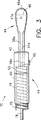
図1は本発明の第1実施例の手前側端の部分断面側面図、
図2は顎部が開いた状態の本発明の第1実施例の先端部の部分透視拡大側面図、
図3は本発明の実施例の先端部の拡大透視頂面図、
図4は顎部が閉じた状態を示す、図2と同様の図、
図5は第1の顎部組立体の開いた状態を示す概略図、
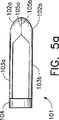
図5aは図5の顎部組立体の閉じた状態を示す概略図、
図6は第2の顎部組立体の開いた状態を示す概略図、
図6aは図6の顎部組立体の閉じた状態を示す概略図、
図7は本発明の顎部組立体の第2実施例の開いた状態を示す概略図、
図7aは図7の顎部組立体の閉じた状態を示す概略図である。
好ましい実施例の詳細な説明
図1から図4を参照すると、複数サンプルバイオプトーム10の第1実施例は手前側ハンドル12と先端作用体14とを含む。軸線方向に変位可能な制御ワイヤ18が貫通して延びる長い可撓性コイル16はハンドル12と先端作用体14とを連結する。コイル16は好ましくは、実質的にその長さ全体にわたってPTFE、FEP又はポリオレフィン外装15と、ハンドル12から延長するコイル部分を覆うひずみ緩和スリーブ17とで覆われている。制御ワイヤ18は好ましくは、適度に可撓性を備えているが、軸線方向には非弾力的であり、理想的には304鋼から形成され、外径が約0.018インチ(約0.46mm)とされる。手前側ハンドル12は中心軸20と変位可能なスプール22とを含む。軸20の手前側端にはつまみリング24が設けられており、軸20の先端部には長手方向の腔26が設けられている。長手方向のスロット28が腔26の手前側端からつまみリング24の先端へ延びている。変位可能なスプール22には中心軸20のスロット28を貫通するクロス部材30が設けられる。クロス部材30には中心貫通穴32と、半径方向に係合する止めねじ34とが設けられる。本発明の第1実施例によれば、短腔36と、半径方向に係合する止めねじ38とがつまみリング24の先端の軸20内に設けられており、腔36は長手方向のスロット28と連通する。この実施例においては、コイル16の手前側端はクロス部材30の中心貫通穴32内を延び、そこで止めねじ34により固定される。制御ワイヤ18の手前側端はスロット28を貫通して短腔36内に挿入され、そこで止めねじ38により保持されている。上記記載から、軸20とスプール22間の相関移動により制御ワイヤ18がコイル16に対し相対移動することが当業者には理解されるであろう。このような動作は以下に詳細に説明するように、先端作用体14を作動させることとなる。
図2から図4を参照すると、先端作用体14は筒状スリーブ40(鋭い先端ナイフエッジ42を有することが好ましい)と顎部組立体44とを含む。顎部組立体44は互いに対向する一対の顎カップ46a、46bを含み、各顎カップは好ましくは半径方向に配列された複数の鋭い歯48a、48bを有する。弾性を備え、好ましくは細いアーム50a、50bは各顎カップ46a、46bから手前側方向へ延びる。筒状のベース部材52はアーム50a、50bの手前側端を接続する。図2に最もよく示されるように、細い弾性アーム50a、50bは筒状ベース部材52と各顎カップ46a、46b間の点51a、51bにおいて相互に離れる方向に屈曲されて顎カップ46a、46bを相互に離れる方向に位置せしめ、それにより各アームの先端部をベース部材の軸線と交差する面内に位置せしめる。筒状ベース部材52は可撓性コイル16の先端に溶着、半田付け、クリンプあるいはその他の適当な方法で連結される。筒状スリーブ40に制御ワイヤ18の屈曲端18aと係合する横穴を設けることによりスリーブ40を制御ワイヤ18の先端に連結する。図2から図4に示すように、制御ワイヤ18の屈曲端18aはスリーブ40の側面の穴45に溶着される。しかし、親出願において詳細に説明されているように、スリーブに対する制御ワイヤの連結はこれ以外の方法でも可能である。筒状スリーブ40は図2及び図3に示されように筒状ベース部材52上に、摺動可能に装着されて図4に示されように弾性アーム50a、50b上を軸線方向に移動可能となっている。
本発明によれば、好ましくは顎カップ46a、46bにはその外面にそれぞれ閉鎖用カム47a、47bが設けられる。各閉鎖用カムは好ましくは、顎カップの表面から先端方向へ隆起する傾斜当接部である。更に、各顎カップの歯部48a、48b(即ち、頂点又は谷部)は好ましくは、顎部を閉鎖したときに図4に示されるようにかつ図5から図7を参照しつつ以下に更に詳細に説明されるように、アームの屈曲部の面に対し角度をなす面内に配列されて各歯部が相互に完全に係合するようにされる。
図3に見られるように、顎カップ46a、46bの断面は偏心しており、断面の最も幅広の位置は線分49で示される。線分49の先端側においては顎カップは実質的に半球形状であり、線分49の手前側においては顎カップは半楕円形状である。閉鎖用カム又は隆起部47a、47bは顎部の最も幅広の部分の手前側、即ち線分49の手前側に位置するのが好ましい。また、顎カップ46a、46bの側壁はアーム50a、50bの方向に傾斜して顎カップからアームに滑らかな接続部が提供される。
以上の説明から、また図1から図4を参照すると、スプール22と軸20とが相互に軸線方向に変位したときに筒状スリーブ40と顎部組立体44とが同様に相互に軸線方向に変位すること、即ち図2に示す位置から図4に示す位置へ、またその逆へ変位することは当業者の理解するところであろう。また、スプール22と軸20とが図1に示すような位置にあるときには筒状スリーブ40と顎部組立体44とが概ね図2に示す位置に位置し、即ち顎部が開いた状態になることが理解されるであろう。したがって、スプール22がつまみリング24の方向へ、或いは逆の方向へ移動せしめられると筒状スリーブ40と顎部組立体44とが概ね図4に示す位置に移動せしめられ、即ち顎部が閉まる状態となることは当業者の更に理解するところであろう。更に、つまみリング24をスプール22に対し移動せしめることはその逆よりも好ましいことが理解されるであろう。何故なら、この場合には逆の場合と違って、筒状スリーブ40を顎部組立体44に対し移動せしめることになるからである。これが望ましいのは、顎部が閉じている間は顎部組立体は組織サンプルから動いて離れないようにするためである。いずれの場合でも、アーム50a、50bが共に筒状スリーブ40により引き抜かれるときに、アームは図4に見られるように、それぞれの屈曲部においてよりもむしろ筒状ベース部材52との連結部において可撓性動作をする傾向がある。アームのこの形状は下記の説明から理解されうるように、顎部の歯部の特別な配列により補償される。
次に、図5及び図5aを参照すると、顎部組立体101は第1の顎カップ102aと第2の顎カップ102bとを含む。各顎カップはそれぞれ対応する弾性アーム103a、103bにより筒状ベース部材104に連結されている。アーム103a、103bはこれらアームがベース部材104に到る点104a、104bにおいて互いに離間する方向(ベース部材の長手方向軸線から離れる方向)へ屈曲されている。顎カップ102a、102bにはそれぞれ切断用エッジ105a、105bが設けられており、これらエッジは一列の歯部を含んでもよく、或いは単なる鋭いエッジであってもよい。スリーブ(図示せず)が顎部組立体上で移動せしめられるとアーム103a、103bが点104a、104bにおいて可撓性動作をして顎部102a、102bが図5aに示されるように合致せしめられ、それにより切断用エッジが相互に係合する。この配列において、顎部が閉じたときにアーム103a、103bが実質的に平行となる位置へ移動することは当業者の理解するところであろう。従って、切断用エッジが顎部のアームに対し実質的に平行な面内に位置するように、各顎部の切断用エッジを配列すべきである。
図2から図4を再度参照すると、先端作用体14の形状と、先端作用体14がコイル16及び引張ワイヤ18とを連結していることとのために、ベース部材52と合致する点において、顎部アーム50a、50bに必要な屈曲51a、51bを設けることは困難である。というのは、ベース部材とアーム屈曲部間には引張ワイヤ18と筒状スリーブ40との連結部(18a、45)を収容するための一定量の空間が必要であるからである。
次いで、図6および図6aを参照すると、上記と同じ顎部組立体101にはそのアーム103a、103b上に、筒状ベース部材104に対し先端側の点において屈曲部104a’、104b’が設けられる。これら屈曲部の位置に係わりなく、スリーブ(図示せず)が顎部組立体上で移動せしめられるとアームはこれらアームの弾性により、ベース部材104との連結部において屈曲せしめられる。図6aに示すように、アーム103a、103bがたわむと顎カップ102a、102bは閉じるが、その切断用エッジ105a、105bは完全に係合しない。その理由は、切断用エッジ105a、105bがアーム103a、103bの先端部分に対し実質的に平行な面内に位置するように配置され、一方、屈曲部104a’、104b’のためにアーム103a、103bが互いに平行の整列状態とならないからである。切断用エッジが完全に係合しないと2つの短所が生ずる。即ち、不完全な切断作用と、露出した鋭いエッジが内視鏡の内部に損傷を与えうることとである。従って、顎部の切断用エッジを完全に係合可能とするには切断用エッジの形状を変えなければならない。
図7及び図7aは本発明による顎部組立体144を示すものである。顎部組立体144は第1の顎カップ146aと第2の顎カップ146bとを含む。各顎カップはそれぞれ対応する弾性アーム150a、150bにより筒状ベース部材152に連結されている。これらアームはベース部材152に対し先端側の点151a、151bにおいて互いに離間する方向(ベース部材の長手方向軸線から離れる方向)に屈曲されている。顎カップ146a、146bには切断用エッジ148a、148bが設けられており、これらエッジはそれぞれのアーム150a、150bの先端部分に対し平行でない(屈曲されている)面内に位置するように配列されている。特に、各切断用エッジは顎部アームの先端部分が位置する面と交差する面内に位置するように配列されている。スリーブ(図示せず)が顎部組立体上で移動せしめられるとアーム150a、150bがベース部材152との連結部においてたわみ、顎部146a、146bが図7aに示されように互いに合致してその切断用エッジ148a、148bが実質的に完全に相互に係合する。
図2及び図4を再度参照すると、顎部アセンブリ44には切断用歯部48a、48bが設けられており、これら歯部は今述べた面内に配列されているので顎部が閉じられたときに歯部は実質的に完全に噛み合うということが理解されるであろう。更に、閉鎖用カム47a、47bは特に顎部の先端部分において顎歯部の完全な噛み合いを補強することが判るであろう。更に、これら閉鎖用カムはスリーブ40が顎カップ上で先端方向へ移動し過ぎないように作用する。このことはスリーブ40が引張ワイヤ18から離脱すべき場合における重要な安全上の利点である。何故なら、この閉鎖用カムは、スリーブがこのバイオプトームから落下して患者の体内で所在不明となることを防止するからである。
本発明のバイオプトームは本明細書において上述した親出願において説明されたと実質的に同様の方法で使用されることは当業者の理解するところであろう。なお、親出願は本明細書と一体のものとして参照される。しかし、本発明のバイオプトームは高度化されたバイト作用を有する。親出願のバイオプトームと同様、顎部組立体は引張ワイヤと、コイルに連結された筒状スリーブとに連結することができ、しかしながらその逆ではない。この連結作用は幾つかの相異なる方法で行うことができる。幾つかの相異なるタイプの作動手段(例えば、鉗子のグリップ)を、本明細書において示すスプールおよびつまみリングの配列とは異なる方法で使用することができる。顎部を、型打ち加工、レーザカット等を含む幾つかの方法により製造することができる。現在好ましい実施例としては、顎部はダイス型打抜き具を使用して410ステンレス鋼シートから平坦なブランクとして形成される。形成されたブランクは、顎カップの外面に対応する凹面と閉鎖用カムに対応する凹面内のへこみを有する型内に置かれる。顎カップの内面に対応する凸面と閉鎖用カムの内側に対応する凸面とを有する打抜き具が平坦なブランクに対し押圧され、顎カップが平坦ブランクから冷間形成される。
本明細書においては内視鏡複数サンプルバイオプトームの幾つかの実施例が説明及び図示されている。本発明に関する特定の実施例が説明されてはいるが、本発明がこれら実施例に限定されることを意図するものではない。本発明はこの技術が許す限りの範囲の広いものであり、また明細書もそのように読まれることを意図するものである。従って、顎部の切断用エッジの特定の形状が開示されてはいるが、別のタイプのものも利用できることが理解されるであろう。特に、切断用エッジは歯部でも、歯部のない鋭いエッジでも、或いはこの両者の組合せでもよい。歯部は半径方向でも又は別の方式でも配列することができる。また、筒状スリーブの先端はナイフ状の鋭いエッジを有するものとして図示され説明されているが、鋭いエッジを持たないスリーブでも本発明の顎部組立体と共に使用することができる。更に、閉鎖用カムに関して特定の形状を説明したが、別の形状も使用できることが判るであろう。例えば、顎部の表面から外方へ隆起した閉鎖用カムの代わりに、顎部自体を、カムが設けられるべき位置において閉じた顎カップの外径が筒の内径よりも大きくなるように、その直径を増大するようにして配置することもできる。換言すると、顎カップは、筒によるカップの閉鎖を高めると共に顎部上での筒の動き過ぎを防止するために、球根状の形状として配置することができる。更に、本発明は手術場所から除去することなしに複数の生検ができる利点を説明したが、所望の場合には、本発明の装置を、一度に一つの生検を実行するように使用することもできる。本発明の精神及び請求の範囲から逸脱することなく、ここに開示された発明に対し種々の修正は可能であることは当業者の理解するところであろう。Technical field
The present invention relates to an endoscopic surgical instrument. In particular, the present invention relates to an instrument for removing a plurality of biopsy tissue samples.
Conventional technology
The endoscopic biopsy procedure is typically performed using an endoscope and an endoscopic biopsy forceps device (biopome). An endoscope is a long flexible tube that carries a fiber lens and has a narrow lumen into which a bioptome is inserted. The bioptome typically includes a long flexible coil that has a pair of opposing jaws at the tip and manual actuation means at the proximal end. When the actuating means is operated, the jaw part opens and closes. At the time of sampling the biopsy tissue, the surgeon guides the endoscope to the biopsy site while looking at the biopsy site via the fiber lens of the endoscope. The bioptome is inserted through the narrow lumen of the endoscope until its opposing jaw reaches the biopsy site. While viewing the biopsy site through the fiber lens of the endoscope, the surgeon positions the jaws around the tissue to be sampled and manipulates the actuation means so that the jaws close around the tissue. The tissue sample is then cut and / or torn from the biopsy site while being captured between the biotome jaws. With the jaws closed, the surgeon pulls the biopome from the endoscope to open the jaws and collects a biopsy tissue sample.
Biopsy tissue sampling means often require the collection of several tissue samples from the same or different biopsy locations. Unfortunately, most biotopomes are limited to the removal of a single tissue sample, and after removal of a single tissue sample, the device can be used with an endoscope before being used to remove another tissue sample. Must be pulled from once. Most biotopomes are limited to the removal of a single sample because the space between the jaws of the biopsy forceps is limited. Several attempts have been made to provide an instrument that allows several tissue samples to be removed before the instrument must be withdrawn once. The problem with providing such an instrument is that the endoscope lumen must be very small due to the narrow lumen of the endoscope, and that the instrument must be inserted to insert the instrument into the endoscope lumen. It must be flexible. Accordingly, some known multi-sample biopsy instruments have been excluded from practical use in endoscopes due to their size and hardness. These include “punch-suction” devices disclosed in US Pat. No. 3,990,033 to Halpern et al. And US Pat. No. 4,522,206 to Whipple et al. Both of these devices have a hollow tube with a punch at the tip and a vacuum source connected to the near end of the hollow tube. The tissue sample is cut off at the punch and sucked from the biopsy site through the hollow tube. However, it is generally recognized that it is virtually impossible to aspirate a tissue sample through a long and narrow flexible biopome.
Efforts have been made to provide multiple sampling capabilities to instruments that must pass through the narrow lumen of an endoscope. These efforts are focused on providing a cylindrical storage space at the tip of the instrument so that several tissue samples can be accumulated before the instrument is withdrawn from the endoscope. For example, U.S. Pat. No. 4,651,753 to Lifton discloses mounting a rigid tubular member to the tip of a first flexible tube. The cylindrical member has a lateral opening, and a concentric cylindrical knife blade is slidably mounted inside the cylindrical member. A second flexible tube concentric with the first tube is coupled to the knife blade to move the knife blade relative to the lateral opening within the tubular member. A third flexible tube having a plunger end is mounted inside the second flexible tube, and a vacuum source (syringe) is connected to the near end of the third tube. To remove the tissue sample, position the lateral opening of the tubular member at the biopsy location, apply a vacuum with a syringe to draw the tissue into the lateral opening, push the second flexible tube forward, and knife blade Is moved across the lateral opening. As a result, the tissue sample is cut and captured inside the cylindrical knife inside the cylindrical member. The third flexible tube is then pushed forward to move its plunger end relative to the tissue sample, and the tissue sample is pushed forward into the cylindrical storage space at the tip of the cylindrical member. About 6 samples can be accumulated in the tubular member and the instrument is then withdrawn from the endoscope. Six samples are collected by removing the tip plug on the tubular member and pushing the third flexible tube so that its plunger end drains the sample.
The Lifton patent apparatus has several obvious disadvantages. First, it is often difficult to obtain a tissue sample transverse to the device. Second, to facilitate the acquisition of lateral samples, a syringe is used to help withdraw tissue into the lateral opening. However, this originally results in a two-step procedure (positioning and cutting) as three steps (positioning, suction, and cutting). In addition, the use of a syringe requires additional manpower. Third, the Lifton patent adds a fourth step to the biopsy procedure because it requires a tissue sample to be pushed into the storage space. Thus, the Lifton patent ultimately demands a substantial burden on surgeons and assistants, many of which are pushing the tube, an idea that goes against classic biopsy sampling. In fact, the preferred mode of operation for all endoscopic instruments is that the gripping action of the instrument tip is made effective by the gripping action of the proximal end of the instrument. The classic biopsy forceps jaws are closed by squeezing a manual actuating member in a syringe-like manner.
A more convenient endoscopic multi-sample biopsy device is disclosed in US Pat. No. 5,171,255 to Rydell. Rydell provides a movable endoscopic instrument having a knife-like cutting tube at the tip. A coaxial anvil is connected to the pull wire and is operated in the same manner as a conventional biopsy forceps. When this anvil is drawn into the cylinder, the tissue located between the anvil and the cylinder is cut and pushed into the storage space inside the cylinder. Several samples are taken and held in the storage space before the device is withdrawn from the endoscope. While this Rydell device is effective in providing a multi-sample instrument where each sample is acquired in a conventional two-step procedure (positioning and cutting), it still remains a problem that often causes lateral cutting. Limited to methods. Conventional biopsy forceps include a jaw that can grip tissue forward or laterally. Even this makes it difficult to position the jaws around the tissue to be collected. Lateral sampling is even more difficult.
US patent application Ser. No. 08 / 189,937, the parent application, discloses an endoscopic multi-sample bioptome having a hollow outer member and an inner member extending therethrough and axially displaceable. . Front ends of the outer and inner members are connected to an actuator so that one can be displaced in the axial direction with respect to the other. The distal end of the outer member is connected to one of a cylinder having a sharp distal edge and the jaw assembly, and the distal end of the inner member is connected to the other. The jaw assembly includes a pair of opposed, preferably toothed jaw cups, each jaw cup connected to a base member by an elastic arm. This elastic arm is bent and presses the jaws away from each other. The base member is mounted inside the cylinder, and the jaw assembly and the cylinder move axially with respect to each other, thereby drawing the elastic arm into the cylinder and causing both of the jaw cups to perform a bite action. However, depending on the shape of the elastic arms, when the cylinder moves on the arms, these arms tend to bend inward to prevent complete closure of the jaws. As a result, an optimum bite effect cannot be obtained.
Summary of the Invention
Accordingly, it is an object of the present invention to provide an endoscopic multiple sample biopome that is not limited to lateral tissue sampling.
Another object of the present invention is to provide an endoscopic multiple sample biopome that is easy to operate.
Another object of the present invention is to provide an endoscopic multi-sample biocome that is not expensive to manufacture.
Yet another object of the present invention is to provide an endoscopic multi-sample bioptome that has all the advantages of conventional biopsy forceps and in addition can collect multiple samples.
Yet another object of the present invention is to provide an endoscopic biopome with a fully closed jaw.
Yet another object of the present invention is to provide an endoscopic biopome having a high bite effect.
In accordance with these objectives, which will be described in detail below, the endoscopic biopome of the present invention includes a relatively long flexible member having a lumen that is axially flexible extending through the lumen. Equipped with sex wires. The flexible member and the near end of the wire are connected to manual actuating means so that one of the flexible member and the wire can be displaced axially relative to the other. The distal end of the flexible member is connected to the jaw assembly. The tip of the wire is connected to a cylinder that can slide on the jaw assembly. The jaw assembly includes a pair of opposing jaw cups, each jaw cup being connected to a base member by a thin arm, and each jaw cup having a sharp cutting edge. The narrow arm of each jaw is an elastic member and includes a portion that is bent away from the longitudinal axis of the tube to position the jaw cups substantially away from each other. The base member of the jaw assembly is attached to the inside of the cylinder, and the arm of the jaw part is pulled into the cylinder by the axial movement with respect to the other of the jaw assembly and the cylinder, or the cylinder of the jaw part is It is moved on the arm so that the chin cup is mated and bite-actuated. In order to ensure that the jaws are completely closed and in a bite working state, a closure cam is provided on the jaw cup. The closure cam is preferably an inclined surface on the outer surface of the jaw cup, which is engaged by the tube to further move the jaw cup to the closed state. Further, to facilitate complete closure of the jaw cup, the closing cam prevents the tube from moving too far in the distal direction on the jaw cup. Further, to facilitate this complete closure, each jaw cup is preferably provided with a cutting edge located in a plane intersecting the plane on which the bend of the jaw arm is located. In addition to facilitating complete closure of the chin cup, this arrangement of cutting edges causes the outer surface of the closed jaw to exhibit a smooth outer surface that is well tolerated by the interior of the endoscope.
Other objects and advantages of the present invention will become apparent to those skilled in the art from the detailed description taken in conjunction with the accompanying drawings.
[Brief description of the drawings]
FIG. 1 is a partial sectional side view of a front side end of a first embodiment of the present invention,
FIG. 2 is a partially see-through enlarged side view of the distal end portion of the first embodiment of the present invention with the jaw portion open,
FIG. 3 is an enlarged perspective top view of the tip of the embodiment of the present invention,
FIG. 4 is a view similar to FIG.
FIG. 5 is a schematic view showing an open state of the first jaw assembly;
FIG. 5a is a schematic diagram showing the closed state of the jaw assembly of FIG.
FIG. 6 is a schematic view showing an open state of the second jaw assembly;
6a is a schematic diagram showing the closed state of the jaw assembly of FIG.
FIG. 7 is a schematic view showing the opened state of the second embodiment of the jaw assembly of the present invention,
FIG. 7a is a schematic view showing the closed state of the jaw assembly of FIG.
Detailed Description of the Preferred Embodiment
With reference to FIGS. 1 to 4, the first embodiment of the
With reference to FIGS. 2-4, the
According to the invention, the
As can be seen in FIG. 3, the cross-sections of the jaw cups 46 a, 46 b are eccentric, and the widest position of the cross-section is indicated by a
From the above description and with reference to FIGS. 1 to 4, when the spool 22 and the
5 and 5a, the
Referring again to FIGS. 2-4, in that the
Next, referring to FIGS. 6 and 6a, the
7 and 7a show a
Referring again to FIGS. 2 and 4,
One skilled in the art will appreciate that the bioptome of the present invention is used in a manner substantially similar to that described in the parent application herein above. The parent application is referred to as an integral part of this specification. However, the bioptome of the present invention has an advanced bite effect. Similar to the parent application bioptome, the jaw assembly can be connected to a pull wire and a cylindrical sleeve connected to a coil, but not vice versa. This coupling action can be done in several different ways. Several different types of actuation means (eg, forceps grips) can be used in different ways from the spool and knob ring arrangements shown herein. The jaws can be manufactured by several methods including stamping, laser cutting and the like. In the presently preferred embodiment, the jaws are formed as a flat blank from a 410 stainless steel sheet using a die punch. The formed blank is placed in a mold having a concave surface corresponding to the outer surface of the chin cup and a recess in the concave surface corresponding to the closing cam. A punching tool having a convex surface corresponding to the inner surface of the jaw cup and a convex surface corresponding to the inner side of the closing cam is pressed against the flat blank, and the jaw cup is cold formed from the flat blank.
Several embodiments of an endoscopic multiple sample biopome are described and illustrated herein. While specific embodiments relating to the invention have been described, it is not intended that the invention be limited to these embodiments. The present invention is as broad as this technology allows, and the specification is intended to be read as such. Thus, although a specific shape of the jaw cutting edge is disclosed, it will be understood that other types may be utilized. In particular, the cutting edge may be a tooth, a sharp edge without a tooth, or a combination of both. The teeth can be arranged in the radial direction or in another manner. Also, the tip of the cylindrical sleeve is shown and described as having a knife-like sharp edge, but a sleeve without a sharp edge can also be used with the jaw assembly of the present invention. Furthermore, while a specific shape has been described for the closure cam, it will be appreciated that other shapes may be used. For example, instead of a closing cam that protrudes outward from the surface of the jaw, the jaw itself is placed so that the outer diameter of the closed jaw cup is larger than the inner diameter of the cylinder at the position where the cam is to be provided. It can also be arranged to increase in diameter. In other words, the chin cup can be arranged as a bulbous shape to increase the closure of the cup by the cylinder and to prevent the cylinder from moving too much on the jaw. Furthermore, while the present invention has described the advantage of having multiple biopsies without removal from the surgical site, the device of the present invention can be used to perform one biopsy at a time if desired. You can also It will be apparent to those skilled in the art that various modifications can be made to the invention disclosed herein without departing from the spirit of the invention and the scope of the claims.
Claims (20)
a)手前側端および先端を有する中空外側部材と、
b)手前側端および先端を有し、前記中空外側部材を介し延びる内側制御部材と、
c)長手方向軸線を有し、前記中空外側部材と前記内側制御部材とのうちの一方の前記先端に連結された筒と、
d)ベース部材と、該ベース部材から先端方向へ延びる一対の弾性アームとを含む顎部組立体であって、前記各弾性アームの先端に切断用エッジを有する顎カップが設けられ、各弾性アームは前記筒の長手方向軸線から離れる方向へ屈曲した部分を有し、前記ベース部材が前記中空外側部材と前記内側制御部材のうちの他方の前記先端に連結されている顎部組立体と、
e)前記中空外側部材の手前側端と前記内側制御部材の手前側端とに連結されて前記中空外側部材と前記内側制御部材とのうちの一方を前記中空外側部材と前記内側制御部材とのうちの他方に対し軸線方向に変位させ、それにより前記筒が前記一対の弾性アーム周りを延びて前記顎カップを閉じるようにする作動手段と、
を具備し、
前記顎カップの前記外側のうちの少なくとも一方が、前記顎カップが閉じられるときに前記筒により係合せしめられる隆起部を含む内視鏡バイオプトーム。In endoscopic bioptome,
a) a hollow outer member having a front end and a tip;
b) an inner control member having a front end and a tip and extending through the hollow outer member;
c) a cylinder having a longitudinal axis and connected to the tip of one of the hollow outer member and the inner control member;
d) A jaw assembly including a base member and a pair of elastic arms extending in the distal direction from the base member, wherein a jaw cup having a cutting edge is provided at the distal end of each elastic arm, and each elastic arm Has a portion bent in a direction away from the longitudinal axis of the cylinder, and a jaw assembly in which the base member is connected to the other tip of the hollow outer member and the inner control member;
e) It is connected to the near side end of the hollow outer member and the near side end of the inner control member, and one of the hollow outer member and the inner control member is connected to the hollow outer member and the inner control member. An actuating means for axially displacing the other of the cylinders, whereby the cylinder extends around the pair of elastic arms and closes the jaw cup;
Comprising
An endoscope bioptome, wherein at least one of the outer sides of the chin cup includes a raised portion that is engaged by the tube when the chin cup is closed.
a)手前側端および先端を有する中空外側部材と、
b)手前側端および先端を有し、前記中空外側部材を介し延びる内側制御部材と、
c)長手方向軸線を有し、前記中空外側部材と前記内側制御部材とのうちの一方の前記先端に連結された筒と、
d)ベース部材と、該ベース部材から先端方向へ延びる一対の弾性アームとを含む顎部組立体であって、前記各弾性アームの先端に切断用エッジを有する顎カップが設けられ、各弾性アームが前記筒の長手方向軸線から離れる方向へ屈曲され、前記ベース部材が前記中空外側部材と前記内側制御部材とのうちの他方の前記先端に連結されている顎部組立体と、
e)前記中空外側部材の手前側端と前記内側制御部材の手前側端とに連結されて前記中空外側部材と前記内側制御部材とのうちの一方を前記中空外側部材と前記内側制御部材とのうちの他方に対し軸線方向に変位させ、それにより前記筒が前記一対の弾性アーム周りを延びて前記顎カップを閉じるようにする作動手段と、
を具備し、
前記筒が鋭い先端エッジを有する内視鏡バイオプトーム。In endoscopic bioptome,
a) a hollow outer member having a front end and a tip;
b) an inner control member having a front end and a tip and extending through the hollow outer member;
c) a cylinder having a longitudinal axis and connected to the tip of one of the hollow outer member and the inner control member;
d) A jaw assembly including a base member and a pair of elastic arms extending in the distal direction from the base member, wherein a jaw cup having a cutting edge is provided at the distal end of each elastic arm, and each elastic arm A jaw assembly that is bent in a direction away from the longitudinal axis of the cylinder, and wherein the base member is connected to the other tip of the hollow outer member and the inner control member;
e) It is connected to the near side end of the hollow outer member and the near side end of the inner control member, and one of the hollow outer member and the inner control member is connected to the hollow outer member and the inner control member. An actuating means for axially displacing the other of the cylinders, whereby the cylinder extends around the pair of elastic arms and closes the jaw cup;
Comprising
An endoscope bioptome in which the tube has a sharp tip edge.
a)長手方向軸線を有するベース部材と、
b)該ベース部材から先端方向に延びる一対の弾性アームであって、各先端に切断用エッジを有する顎カップが設けられている一対の弾性アームと、を具備し、
前記顎カップのうちの少なくとも一方に閉鎖用カムが設けられている
顎部組立体。In the jaw assembly used in the endoscopic bioptome,
a) a base member having a longitudinal axis;
b) a pair of resilient arms extending distally from said base member, comprising a pair of resilient arms chin cup having a cutting edge on each tip is provided, the,
A jaw assembly, wherein at least one of said jaw cups is provided with a closing cam .
a)長手方向軸線を有するベース部材と、
b)該ベース部材から先端方向に延びる一対の弾性アームであって、各弾性アームが前記ベース部材の長手方向軸線から離れる方向に屈曲されて前記ベース部材の長手方向軸線と交差する内面に位置する部分を有し、弾性アームの各先端に切断用エッジを有する顎カップが設けられ、エッジが、前記弾性アームが位置する面と交差する面内に位置する一対の弾性アームと、
を具備し、
前記顎カップのうちの少なくとも一方に閉鎖用カムが設けられている
顎部組立体。In the jaw assembly used in the endoscopic bioptome,
a) a base member having a longitudinal axis;
b) A pair of elastic arms extending in the distal direction from the base member, each elastic arm being bent in a direction away from the longitudinal axis of the base member and positioned on the inner surface intersecting the longitudinal axis of the base member A pair of elastic arms having a portion, provided with a chin cup having a cutting edge at each tip of the elastic arm, the edge being located in a plane intersecting the plane where the elastic arm is located;
Comprising
A jaw assembly in which at least one of the jaw cups is provided with a closing cam.
Applications Claiming Priority (3)
| Application Number | Priority Date | Filing Date | Title |
|---|---|---|---|
| US08/412,058 US5636639A (en) | 1992-02-18 | 1995-03-28 | Endoscopic multiple sample bioptome with enhanced biting action |
| US08/412,058 | 1995-03-28 | ||
| PCT/US1996/004145 WO1996029936A1 (en) | 1995-03-28 | 1996-03-27 | Endoscopic multiple sample bioptome with enhanced biting action |
Publications (2)
| Publication Number | Publication Date |
|---|---|
| JPH11502744A JPH11502744A (en) | 1999-03-09 |
| JP3708552B2 true JP3708552B2 (en) | 2005-10-19 |
Family
ID=23631420
Family Applications (1)
| Application Number | Title | Priority Date | Filing Date |
|---|---|---|---|
| JP52960596A Expired - Fee Related JP3708552B2 (en) | 1995-03-28 | 1996-03-27 | Endoscopic bioptome and jaw assembly |
Country Status (7)
| Country | Link |
|---|---|
| US (4) | US5636639A (en) |
| EP (1) | EP0817593B1 (en) |
| JP (1) | JP3708552B2 (en) |
| AU (1) | AU696599B2 (en) |
| CA (1) | CA2216554A1 (en) |
| DE (1) | DE69636220T2 (en) |
| WO (1) | WO1996029936A1 (en) |
Cited By (1)
| Publication number | Priority date | Publication date | Assignee | Title |
|---|---|---|---|---|
| WO2019099752A1 (en) * | 2017-11-15 | 2019-05-23 | United States Endoscopy Group, Inc. | End effectors actuation platform |
Families Citing this family (115)
| Publication number | Priority date | Publication date | Assignee | Title |
|---|---|---|---|---|
| US5636639A (en) * | 1992-02-18 | 1997-06-10 | Symbiosis Corporation | Endoscopic multiple sample bioptome with enhanced biting action |
| US6142956A (en) | 1996-11-25 | 2000-11-07 | Symbiosis Corporation | Proximal actuation handle for a biopsy forceps instrument having irrigation and aspiration capabilities |
| US5897507A (en) * | 1996-11-25 | 1999-04-27 | Symbiosis Corporation | Biopsy forceps instrument having irrigation and aspiration capabilities |
| US6331165B1 (en) * | 1996-11-25 | 2001-12-18 | Scimed Life Systems, Inc. | Biopsy instrument having irrigation and aspiration capabilities |
| US7347828B2 (en) * | 1996-11-25 | 2008-03-25 | Boston Scientific Miami Corporation | Suction adapter for medical instrument |
| CA2280880A1 (en) | 1997-03-13 | 1998-09-17 | Calum Eric Macaulay | Validating and processing fluorescence spectral data for detecting the rejection of transplanted tissue |
| US6461310B1 (en) | 1997-10-29 | 2002-10-08 | Symbiosis Corp | Endoscopic bioptome with a hard stop to control biting force |
| US6527767B2 (en) * | 1998-05-20 | 2003-03-04 | New England Medical Center | Cardiac ablation system and method for treatment of cardiac arrhythmias and transmyocardial revascularization |
| JP3882876B2 (en) * | 1998-11-13 | 2007-02-21 | 株式会社セガ | Medal game device |
| US6083150A (en) * | 1999-03-12 | 2000-07-04 | C. R. Bard, Inc. | Endoscopic multiple sample biopsy forceps |
| US6537205B1 (en) * | 1999-10-14 | 2003-03-25 | Scimed Life Systems, Inc. | Endoscopic instrument system having reduced backlash control wire action |
| ITCE990004A1 (en) * | 1999-10-25 | 2000-01-25 | Mario Immacolato Paternuosto | VALVE FOR BIOPSY FORCEPS IN DIGESTIVE ENDOSCOPY |
| US20020198551A1 (en) * | 1999-11-16 | 2002-12-26 | Grant Kevin Lee | Endoscopic tissue separator surgical device |
| US6569105B1 (en) * | 2000-09-14 | 2003-05-27 | Syntheon, Llc | Rotatable and deflectable biopsy forceps |
| US7341564B2 (en) * | 2001-05-03 | 2008-03-11 | Boston Scientific Scimed, Inc. | Biopsy forceps device with transparent outer sheath |
| FR2828088A1 (en) * | 2001-08-03 | 2003-02-07 | Artbois Sarl | Instrument to take sample of brain tissue, from brain cavity of sheep, has tube to be inserted through hole into cavity with extending tool structure of alignment arms and cutting tools |
| US7169167B2 (en) * | 2001-12-04 | 2007-01-30 | Scimed Life Systems, Inc. | Endoscopic apparatus and method |
| US7837631B2 (en) * | 2003-03-14 | 2010-11-23 | Boston Scientific Scimed Inc. | Biopsy forceps with removable jaw segments |
| US8469993B2 (en) | 2003-06-18 | 2013-06-25 | Boston Scientific Scimed, Inc. | Endoscopic instruments |
| US20040260337A1 (en) * | 2003-06-18 | 2004-12-23 | Scimed Life Systems, Inc. | Endoscopic instruments and methods of manufacture |
| US7588545B2 (en) | 2003-09-10 | 2009-09-15 | Boston Scientific Scimed, Inc. | Forceps and collection assembly with accompanying mechanisms and related methods of use |
| AR041956A1 (en) | 2003-11-13 | 2005-06-01 | Ernesto Guillermo Cadeiras | BIOTOMO WITH DISPOSABLE CUTTING CLAMP |
| US7942896B2 (en) | 2003-11-25 | 2011-05-17 | Scimed Life Systems, Inc. | Forceps and collection assembly and related methods of use and manufacture |
| US7905857B2 (en) | 2005-07-11 | 2011-03-15 | Covidien Ag | Needle assembly including obturator with safety reset |
| US7850650B2 (en) * | 2005-07-11 | 2010-12-14 | Covidien Ag | Needle safety shield with reset |
| US7828773B2 (en) * | 2005-07-11 | 2010-11-09 | Covidien Ag | Safety reset key and needle assembly |
| US7546089B2 (en) * | 2004-12-23 | 2009-06-09 | Triquint Semiconductor, Inc. | Switchable directional coupler for use with RF devices |
| ATE440552T1 (en) * | 2005-01-20 | 2009-09-15 | Wilson Cook Medical Inc | BIOPSY FORCEPS |
| US7762960B2 (en) | 2005-05-13 | 2010-07-27 | Boston Scientific Scimed, Inc. | Biopsy forceps assemblies |
| US20060276747A1 (en) | 2005-06-06 | 2006-12-07 | Sherwood Services Ag | Needle assembly with removable depth stop |
| US7731692B2 (en) * | 2005-07-11 | 2010-06-08 | Covidien Ag | Device for shielding a sharp tip of a cannula and method of using the same |
| US20160001064A1 (en) | 2005-07-22 | 2016-01-07 | The Spectranetics Corporation | Endocardial lead cutting apparatus |
| US8097012B2 (en) * | 2005-07-27 | 2012-01-17 | The Spectranetics Corporation | Endocardial lead removing apparatus |
| US8696671B2 (en) * | 2005-07-29 | 2014-04-15 | Vertos Medical Inc. | Percutaneous tissue excision devices |
| US7654735B2 (en) | 2005-11-03 | 2010-02-02 | Covidien Ag | Electronic thermometer |
| WO2007070797A2 (en) | 2005-12-13 | 2007-06-21 | Cordis Development Corporation | Detachment actuator for use with medical device deployment systems |
| US7942894B2 (en) * | 2006-01-31 | 2011-05-17 | Codman & Shurtleff, Inc. | Embolic device delivery system |
| US7918783B2 (en) * | 2006-03-22 | 2011-04-05 | Boston Scientific Scimed, Inc. | Endoscope working channel with multiple functionality |
| US7998167B2 (en) * | 2006-04-14 | 2011-08-16 | Ethicon Endo-Surgery, Inc. | End effector and method of manufacture |
| US20070244513A1 (en) * | 2006-04-14 | 2007-10-18 | Ethicon Endo-Surgery, Inc. | Endoscopic device |
| US7857827B2 (en) * | 2006-04-14 | 2010-12-28 | Ethicon Endo-Surgery, Inc. | Endoscopic device |
| US20070244509A1 (en) * | 2006-04-14 | 2007-10-18 | Ethicon Endo-Surgery, Inc. | Endoscopic device |
| US7942830B2 (en) | 2006-05-09 | 2011-05-17 | Vertos Medical, Inc. | Ipsilateral approach to minimally invasive ligament decompression procedure |
| US8062325B2 (en) | 2006-07-31 | 2011-11-22 | Codman & Shurtleff, Inc. | Implantable medical device detachment system and methods of using the same |
| US8366720B2 (en) | 2006-07-31 | 2013-02-05 | Codman & Shurtleff, Inc. | Interventional medical device system having an elongation retarding portion and method of using the same |
| US8414616B2 (en) * | 2006-09-12 | 2013-04-09 | Pioneer Surgical Technology, Inc. | Mounting devices for fixation devices and insertion instruments used therewith |
| CN201019780Y (en) | 2007-04-24 | 2008-02-13 | 南京微创医学科技有限公司 | biopsy forceps |
| US8357104B2 (en) * | 2007-11-01 | 2013-01-22 | Coviden Lp | Active stylet safety shield |
| US9095328B2 (en) | 2008-12-12 | 2015-08-04 | Boston Scientific Scimed, Inc. | Endoscopes having multiple lumens for tissue acquisition and removal and related methods of use |
| WO2011066470A1 (en) | 2009-11-25 | 2011-06-03 | Clements Robert M | Device and system for multiple core biopsy |
| US10219826B2 (en) | 2010-07-14 | 2019-03-05 | Seg-Way Orthopaedics, Inc. | Method and apparatus for endoscopic ligament release |
| US9428254B1 (en) | 2010-09-24 | 2016-08-30 | Katalyst Surgical, Llc | Microsurgical handle and instrument |
| US8777898B2 (en) | 2011-01-31 | 2014-07-15 | Boston Scientific Scimed, Inc. | Medical devices having releasable coupling |
| US8821444B2 (en) | 2011-10-03 | 2014-09-02 | Katalyst Surgical, Llc | Multi-utility surgical instrument |
| US9999407B2 (en) | 2012-01-21 | 2018-06-19 | Choon Kee Lee | Tissue sampling device |
| US9138346B2 (en) | 2012-01-26 | 2015-09-22 | Katalyst Surgical, Llc | Surgical instrument sleeve |
| US9629645B2 (en) | 2012-10-30 | 2017-04-25 | Katalyst Surgical, Llc | Atraumatic microsurgical forceps |
| US9226762B2 (en) | 2012-11-07 | 2016-01-05 | Katalyst Surgical, Llc | Atraumatic microsurgical forceps |
| US20140257370A1 (en) * | 2013-03-05 | 2014-09-11 | Covidien Lp | Anvil Grasper |
| US9204995B2 (en) | 2013-03-12 | 2015-12-08 | Katalyst Surgical, Llc | Membrane removing forceps |
| US9427251B2 (en) | 2013-03-13 | 2016-08-30 | Covidien Lp | Saber tooth harvester |
| RU2535908C1 (en) * | 2013-05-13 | 2014-12-20 | Государственное бюджетное образовательное учреждение высшего профессионального образования "Дальневосточный государственный медицинский университет" Министерства здравоохранения Российской Федерации | Forceps for removal of organs in laparoscopic operations |
| EP3043719B1 (en) * | 2013-09-12 | 2022-04-13 | Transmed7, LLC | Tissue coring biopsy devices |
| US20150088193A1 (en) * | 2013-09-24 | 2015-03-26 | Katalyst Surgical, Llc | Membrane removing forceps |
| CA2932082C (en) | 2013-11-27 | 2023-06-20 | Seg-Way Orthopaedics, Inc. | Surgical guide |
| US9707005B2 (en) | 2014-02-14 | 2017-07-18 | Ethicon Llc | Lockout mechanisms for surgical devices |
| US10022267B2 (en) | 2014-04-21 | 2018-07-17 | Katalyst Surgical, Llc | Method of manufacturing a microsurgical instrument tip |
| AU2015249652B2 (en) | 2014-04-23 | 2020-02-20 | Applied Medical Resources Corporation | Systems and methods for tissue removal |
| US9918718B2 (en) | 2014-08-08 | 2018-03-20 | DePuy Synthes Products, Inc. | Embolic coil delivery system with retractable mechanical release mechanism |
| JP6602846B2 (en) | 2014-08-18 | 2019-11-06 | アプライド メディカル リソーシーズ コーポレイション | Tissue containment / recovery system and method |
| US9775943B2 (en) | 2014-10-10 | 2017-10-03 | Katalyst Surgical, Llc | Cannula ingress system |
| CA3211010C (en) | 2014-11-13 | 2025-09-09 | Applied Medical Resources Corporation | Systems and methods for tissue removal |
| WO2016154518A1 (en) * | 2015-03-26 | 2016-09-29 | United States Endoscopy Group, Inc. | Endoscopic grasping device |
| USD779668S1 (en) | 2015-03-26 | 2017-02-21 | United States Endoscopy Group, Inc. | Grasper |
| JP7080642B2 (en) | 2015-04-23 | 2022-06-06 | アプライド メディカル リソーシーズ コーポレイション | Tissue retrieval system and method |
| CA2998539A1 (en) * | 2015-09-15 | 2017-03-23 | Cook Medical Technologies Llc | Forceps with locking mechanism |
| JP6896746B2 (en) | 2016-01-22 | 2021-06-30 | アプライド メディカル リソーシーズ コーポレイション | Systems and methods for tissue removal |
| WO2017218161A1 (en) | 2016-06-16 | 2017-12-21 | Katalyst Surgical, Llc | Reusable instrument handle with single- use tip |
| US10617441B2 (en) | 2016-09-07 | 2020-04-14 | Vertos Medical, Inc. | Percutaneous lateral recess resection methods and instruments |
| ES2949144T3 (en) | 2016-11-23 | 2023-09-26 | Corit Medical Llc | Tissue reduction apparatus |
| US10695043B2 (en) | 2017-02-21 | 2020-06-30 | Katalyst Surgical, Llc | Surgical instrument subcomponent integration by additive manufacturing |
| US20190150967A1 (en) * | 2017-11-15 | 2019-05-23 | United States Endoscopy Group, Inc. | Avulsion forceps |
| US10806462B2 (en) | 2017-12-21 | 2020-10-20 | DePuy Synthes Products, Inc. | Implantable medical device detachment system with split tube and cylindrical coupling |
| US10806461B2 (en) * | 2018-04-27 | 2020-10-20 | DePuy Synthes Products, Inc. | Implantable medical device detachment system with split tube |
| US10849640B2 (en) | 2018-05-23 | 2020-12-01 | Katalyst Surgical, Llc | Membrane aggregating forceps |
| KR102765681B1 (en) | 2018-09-20 | 2025-02-11 | 어플라이드 메디컬 리소시스 코포레이션 | Tissue Removal Containment Systems |
| US11147562B2 (en) | 2018-12-12 | 2021-10-19 | DePuy Synthes Products, Inc. | Systems and methods for embolic implant detachment |
| US11253265B2 (en) | 2019-06-18 | 2022-02-22 | DePuy Synthes Products, Inc. | Pull wire detachment for intravascular devices |
| US11207494B2 (en) | 2019-07-03 | 2021-12-28 | DePuy Synthes Products, Inc. | Medical device delivery member with flexible stretch resistant distal portion |
| US11426174B2 (en) | 2019-10-03 | 2022-08-30 | DePuy Synthes Products, Inc. | Medical device delivery member with flexible stretch resistant mechanical release |
| US11529186B2 (en) | 2019-07-22 | 2022-12-20 | Covidien Lp | Electrosurgical forceps including thermal cutting element |
| US11510662B2 (en) | 2019-07-24 | 2022-11-29 | Covidien Lp | Free standing bag with integrated cutting guard interface |
| EP4003138A4 (en) * | 2019-07-25 | 2023-08-30 | Uroviu Corp. | Disposable endoscopy cannula with integrated grasper |
| US12376859B2 (en) | 2019-09-17 | 2025-08-05 | DePuy Synthes Products, Inc. | Embolic coil proximal connecting element and stretch resistant fiber |
| US11439403B2 (en) | 2019-09-17 | 2022-09-13 | DePuy Synthes Products, Inc. | Embolic coil proximal connecting element and stretch resistant fiber |
| US11376013B2 (en) | 2019-11-18 | 2022-07-05 | DePuy Synthes Products, Inc. | Implant delivery system with braid cup formation |
| US11457922B2 (en) | 2020-01-22 | 2022-10-04 | DePuy Synthes Products, Inc. | Medical device delivery member with flexible stretch resistant distal portion |
| US11432822B2 (en) | 2020-02-14 | 2022-09-06 | DePuy Synthes Products, Inc. | Intravascular implant deployment system |
| US11364051B2 (en) | 2020-02-20 | 2022-06-21 | Covidien Lp | Cutting guard |
| US11951026B2 (en) | 2020-06-30 | 2024-04-09 | DePuy Synthes Products, Inc. | Implantable medical device detachment system with flexible braid section |
| CN111643201B (en) * | 2020-07-02 | 2021-06-01 | 西安交通大学口腔医院 | Clamping device for oral tooth implantation |
| US12048472B2 (en) | 2021-02-01 | 2024-07-30 | Covidien Lp | Electrosurgical instruments, jaw members thereof, and methods of manufacturing |
| US11998213B2 (en) | 2021-07-14 | 2024-06-04 | DePuy Synthes Products, Inc. | Implant delivery with modified detachment feature and pull wire engagement |
| US11844490B2 (en) | 2021-12-30 | 2023-12-19 | DePuy Synthes Products, Inc. | Suture linkage for inhibiting premature embolic implant deployment |
| US11937824B2 (en) | 2021-12-30 | 2024-03-26 | DePuy Synthes Products, Inc. | Implant detachment systems with a modified pull wire |
| US12508032B2 (en) | 2021-12-31 | 2025-12-30 | DePuy Synthes Products, Inc. | Medical device delivery systems with twisting loop wires |
| US12011171B2 (en) | 2022-01-06 | 2024-06-18 | DePuy Synthes Products, Inc. | Systems and methods for inhibiting premature embolic implant deployment |
| US11937825B2 (en) | 2022-03-02 | 2024-03-26 | DePuy Synthes Products, Inc. | Hook wire for preventing premature embolic implant detachment |
| US12471924B2 (en) | 2022-03-02 | 2025-11-18 | DePuy Synthes Products, Inc. | Flexible feature for embolic implant deployment |
| US12137915B2 (en) | 2022-03-03 | 2024-11-12 | DePuy Synthes Products, Inc. | Elongating wires for inhibiting premature implant detachment |
| US11937826B2 (en) | 2022-03-14 | 2024-03-26 | DePuy Synthes Products, Inc. | Proximal link wire for preventing premature implant detachment |
| EP4539756A1 (en) | 2022-06-16 | 2025-04-23 | Vertos Medical, Inc. | Integrated instrument assembly |
| US12402886B2 (en) | 2022-06-23 | 2025-09-02 | DePuy Synthes Products, Inc. | Detachment indicator for implant deployment |
| US12446888B2 (en) | 2022-08-26 | 2025-10-21 | Depuy Synthes Products, Inc | Twister implant detachment mechanism |
| US12396730B2 (en) | 2022-09-28 | 2025-08-26 | DePuy Synthes Products, Inc. | Braided implant with detachment mechanism |
Family Cites Families (50)
| Publication number | Priority date | Publication date | Assignee | Title |
|---|---|---|---|---|
| US2850007A (en) | 1956-05-31 | 1958-09-02 | American Cyanamid Co | Biopsy device |
| US3001522A (en) | 1957-12-26 | 1961-09-26 | Silverman Irving | Biopsy device |
| US3175554A (en) | 1963-03-26 | 1965-03-30 | Becton Dickinson Co | Split biopsy needle |
| US3590808A (en) | 1968-09-04 | 1971-07-06 | Us Catheter & Instr Corp | Biopsy tool |
| US4016881A (en) * | 1973-07-04 | 1977-04-12 | Centre De Recherche Industrielle Du Quebec | Instrument for use in laparoscopic tubal cauterization |
| US3989049A (en) * | 1973-07-30 | 1976-11-02 | In Bae Yoon | Method of applying an elastic ring to an anatomical tubular structure |
| AR196829A1 (en) * | 1973-12-06 | 1974-02-19 | Halpern D | SURGICAL INSTRUMENT FOR BIOPSIES |
| US5133727A (en) | 1990-05-10 | 1992-07-28 | Symbiosis Corporation | Radial jaw biopsy forceps |
| GB2022421B (en) | 1978-06-08 | 1982-09-15 | Wolf Gmbh Richard | Devices for obtaining tissure samples |
| US4200111A (en) * | 1978-09-21 | 1980-04-29 | Harris Arthur M | Specimen removal instrument |
| US4393872A (en) | 1980-05-27 | 1983-07-19 | Eder Instrument Co., Inc. | Aspirating surgical forceps |
| FR2505170B1 (en) * | 1981-05-06 | 1985-08-02 | Metallisations Traitements Opt | BIOPSY TONGS |
| US4522206A (en) | 1983-01-26 | 1985-06-11 | Dyonics, Inc. | Surgical instrument |
| US4651753A (en) | 1984-10-12 | 1987-03-24 | Jayco Pharmaceuticals | Endoscopic multiple biopsy instrument |
| US4651752A (en) | 1985-03-08 | 1987-03-24 | Fuerst Erwin J | Biopsy needle |
| FR2582504A1 (en) | 1985-06-04 | 1986-12-05 | Schintgen Jean Marie | IMPROVEMENTS ON BIOPSY CLAMPS |
| US4721116A (en) | 1985-06-04 | 1988-01-26 | Schintgen Jean Marie | Retractable needle biopsy forceps and improved control cable therefor |
| US4644951A (en) | 1985-09-16 | 1987-02-24 | Concept, Inc. | Vacuum sleeve for a surgical appliance |
| DE3630203A1 (en) | 1986-09-04 | 1988-03-17 | Wisap Gmbh | TISSUE PUNCHING |
| JPH0755222B2 (en) * | 1986-12-12 | 1995-06-14 | オリンパス光学工業株式会社 | Treatment tool |
| US4733662A (en) | 1987-01-20 | 1988-03-29 | Minnesota Mining And Manufacturing Company | Tissue gripping and cutting assembly for surgical instrument |
| DE8702446U1 (en) | 1987-02-18 | 1987-10-08 | Kothe, Lutz, 7760 Radolfzell | Medical device |
| US5049152A (en) * | 1989-03-07 | 1991-09-17 | Richard-Allan Medical Industries | Hemostatic clip applicator |
| US5052402A (en) * | 1989-01-31 | 1991-10-01 | C.R. Bard, Inc. | Disposable biopsy forceps |
| EP0380874A1 (en) * | 1989-01-31 | 1990-08-08 | C.R. Bard, Inc. | Disposable biopsy forceps |
| US5632746A (en) | 1989-08-16 | 1997-05-27 | Medtronic, Inc. | Device or apparatus for manipulating matter |
| US5085658A (en) | 1989-09-05 | 1992-02-04 | Percutaneous Technologies | Neurosurgical pathological tissue removing device |
| US5505210A (en) | 1989-11-06 | 1996-04-09 | Mectra Labs, Inc. | Lavage with tissue cutting cannula |
| US5665100A (en) | 1989-12-05 | 1997-09-09 | Yoon; Inbae | Multifunctional instrument with interchangeable operating units for performing endoscopic procedures |
| US6099550A (en) * | 1989-12-05 | 2000-08-08 | Yoon; Inbae | Surgical instrument having jaws and an operating channel and method for use thereof |
| US5228451A (en) | 1990-05-10 | 1993-07-20 | Symbiosis Corporation | Biopsy forceps device having stiff distal end |
| US5171255A (en) | 1990-11-21 | 1992-12-15 | Everest Medical Corporation | Biopsy device |
| US5082000A (en) | 1990-11-29 | 1992-01-21 | Applied Medical Technology, Inc. | Biopsy forceps with calde controlled jaws |
| US5300087A (en) | 1991-03-22 | 1994-04-05 | Knoepfler Dennis J | Multiple purpose forceps |
| DE4114311A1 (en) | 1991-05-02 | 1992-11-12 | Harald Heidmueller | EXTRACTOR |
| US5217468A (en) | 1991-10-24 | 1993-06-08 | Mectra Labs, Inc. | Tissue encapsulating sheath |
| US5433725A (en) | 1991-12-13 | 1995-07-18 | Unisurge, Inc. | Hand-held surgical device and tools for use therewith, assembly and method |
| US5636639A (en) * | 1992-02-18 | 1997-06-10 | Symbiosis Corporation | Endoscopic multiple sample bioptome with enhanced biting action |
| US5222973A (en) * | 1992-03-09 | 1993-06-29 | Sharpe Endosurgical Corporation | Endoscopic grasping tool surgical instrument |
| US5217458A (en) | 1992-04-09 | 1993-06-08 | Everest Medical Corporation | Bipolar biopsy device utilizing a rotatable, single-hinged moving element |
| US5318589A (en) * | 1992-04-15 | 1994-06-07 | Microsurge, Inc. | Surgical instrument for endoscopic surgery |
| US5195533A (en) | 1992-05-08 | 1993-03-23 | Boston Scientific Corporation | Biopsy needle instrument for storing multiple specimens |
| US5238002A (en) * | 1992-06-08 | 1993-08-24 | C. R. Bard, Inc. | Disposable biopsy forceps |
| US5251641A (en) | 1992-07-29 | 1993-10-12 | Hgg Laser Fare, Inc. | Biopsy needle |
| US5234000A (en) | 1992-09-25 | 1993-08-10 | Hakky Said I | Automatic biopsy device housing a plurality of stylets |
| US5334198A (en) | 1992-10-09 | 1994-08-02 | Innovasive Devices, Inc. | Surgical instrument |
| DE4308627A1 (en) * | 1993-03-18 | 1994-09-22 | Eisold Wolfgang | Medical endoscopic instruments with sliding mechanism for opening and closing the bit parts designed, in particular, as tubular shaft instruments for surgical instruments for endoscopic interventions |
| US5419774A (en) | 1993-07-13 | 1995-05-30 | Scimed Life Systems, Inc. | Thrombus extraction device |
| EP0722286B1 (en) * | 1993-09-20 | 2002-08-21 | Boston Scientific Corporation | Multiple biopsy sampling device |
| US5810876A (en) | 1995-10-03 | 1998-09-22 | Akos Biomedical, Inc. | Flexible forceps device |
-
1995
- 1995-03-28 US US08/412,058 patent/US5636639A/en not_active Expired - Lifetime
-
1996
- 1996-03-27 JP JP52960596A patent/JP3708552B2/en not_active Expired - Fee Related
- 1996-03-27 DE DE69636220T patent/DE69636220T2/en not_active Expired - Fee Related
- 1996-03-27 CA CA002216554A patent/CA2216554A1/en not_active Abandoned
- 1996-03-27 EP EP96910581A patent/EP0817593B1/en not_active Expired - Lifetime
- 1996-03-27 AU AU53738/96A patent/AU696599B2/en not_active Ceased
- 1996-03-27 WO PCT/US1996/004145 patent/WO1996029936A1/en not_active Ceased
- 1996-12-20 US US08/771,576 patent/US5746216A/en not_active Expired - Lifetime
-
1998
- 1998-05-04 US US09/071,039 patent/US6193671B1/en not_active Expired - Fee Related
-
2000
- 2000-11-20 US US09/715,268 patent/US6561988B1/en not_active Expired - Fee Related
Cited By (2)
| Publication number | Priority date | Publication date | Assignee | Title |
|---|---|---|---|---|
| WO2019099752A1 (en) * | 2017-11-15 | 2019-05-23 | United States Endoscopy Group, Inc. | End effectors actuation platform |
| US11033288B2 (en) | 2017-11-15 | 2021-06-15 | United States Endoscopy Group, Inc. | End effectors actuation platform |
Also Published As
| Publication number | Publication date |
|---|---|
| AU5373896A (en) | 1996-10-16 |
| EP0817593B1 (en) | 2006-06-07 |
| CA2216554A1 (en) | 1996-10-03 |
| EP0817593A1 (en) | 1998-01-14 |
| US6193671B1 (en) | 2001-02-27 |
| US6561988B1 (en) | 2003-05-13 |
| WO1996029936A1 (en) | 1996-10-03 |
| AU696599B2 (en) | 1998-09-17 |
| US5636639A (en) | 1997-06-10 |
| JPH11502744A (en) | 1999-03-09 |
| DE69636220T2 (en) | 2007-04-19 |
| DE69636220D1 (en) | 2006-07-20 |
| US5746216A (en) | 1998-05-05 |
Similar Documents
| Publication | Publication Date | Title |
|---|---|---|
| JP3708552B2 (en) | Endoscopic bioptome and jaw assembly | |
| US5797957A (en) | Endoscopic bioptome with a hard stop to control biting force | |
| EP0843533B1 (en) | Endoscopic multiple sample bioptome | |
| US6083150A (en) | Endoscopic multiple sample biopsy forceps | |
| US5762069A (en) | Multiple sample biopsy forceps | |
| US5895361A (en) | Esophageal biopsy jaw assembly and endoscopic instrument incorporating the same | |
| US5643307A (en) | Colposcopic biopsy punch with removable multiple sample basket | |
| US5082000A (en) | Biopsy forceps with calde controlled jaws | |
| US5707392A (en) | Hermaphroditic stamped forceps jaw for disposable endoscopic biopsy forceps and method of making the same | |
| US6419640B1 (en) | Multiple-specimen, endoscopic biopsy forceps | |
| US6273860B1 (en) | Biopsy apparatus | |
| WO2000007502A1 (en) | Articulated medical device | |
| US20200054309A1 (en) | Jaw assembly for surgical tool and biopsy sample collection member | |
| US20050137585A1 (en) | Back loading endoscopic instruments | |
| US6461310B1 (en) | Endoscopic bioptome with a hard stop to control biting force | |
| US20050113867A1 (en) | Forceps and collection assembly and related methods of use and manufacture | |
| WO1999007288A1 (en) | Multiple sample biopsy forceps |
Legal Events
| Date | Code | Title | Description |
|---|---|---|---|
| A131 | Notification of reasons for refusal |
Free format text: JAPANESE INTERMEDIATE CODE: A131 Effective date: 20041124 |
|
| A601 | Written request for extension of time |
Free format text: JAPANESE INTERMEDIATE CODE: A601 Effective date: 20050224 |
|
| A602 | Written permission of extension of time |
Free format text: JAPANESE INTERMEDIATE CODE: A602 Effective date: 20050411 |
|
| A521 | Request for written amendment filed |
Free format text: JAPANESE INTERMEDIATE CODE: A523 Effective date: 20050523 |
|
| TRDD | Decision of grant or rejection written | ||
| A01 | Written decision to grant a patent or to grant a registration (utility model) |
Free format text: JAPANESE INTERMEDIATE CODE: A01 Effective date: 20050705 |
|
| A61 | First payment of annual fees (during grant procedure) |
Free format text: JAPANESE INTERMEDIATE CODE: A61 Effective date: 20050804 |
|
| R150 | Certificate of patent or registration of utility model |
Free format text: JAPANESE INTERMEDIATE CODE: R150 |
|
| FPAY | Renewal fee payment (event date is renewal date of database) |
Free format text: PAYMENT UNTIL: 20090812 Year of fee payment: 4 |
|
| FPAY | Renewal fee payment (event date is renewal date of database) |
Free format text: PAYMENT UNTIL: 20100812 Year of fee payment: 5 |
|
| LAPS | Cancellation because of no payment of annual fees |