JP3707737B2 - Outdoor heat exchanger - Google Patents
Outdoor heat exchanger Download PDFInfo
- Publication number
- JP3707737B2 JP3707737B2 JP2003060502A JP2003060502A JP3707737B2 JP 3707737 B2 JP3707737 B2 JP 3707737B2 JP 2003060502 A JP2003060502 A JP 2003060502A JP 2003060502 A JP2003060502 A JP 2003060502A JP 3707737 B2 JP3707737 B2 JP 3707737B2
- Authority
- JP
- Japan
- Prior art keywords
- water
- pipe
- heat exchanger
- outdoor heat
- heat transfer
- Prior art date
- Legal status (The legal status is an assumption and is not a legal conclusion. Google has not performed a legal analysis and makes no representation as to the accuracy of the status listed.)
- Expired - Fee Related
Links
Images


Description
【0001】
【発明の属する技術分野】
本発明は、空冷式冷凍機、空調機などに用いられる屋外熱交換器に関し、特に冷却能力を安定させ、省エネルギー性、メンテナンス性、耐久性を向上させた屋外熱交換器に関する。
【0002】
【従来の技術】
従来の空冷式冷凍機などに利用される屋外熱交換器は、銅管の冷却能力を増すために伝熱フィンをつけているが、伝熱フィンとして好適に用いられるアルミ板は、車両から排出される亜硫酸ガスや窒素酸化ガス、炭酸ガス、酸性雨の他、酸化性パーティキュレートなどによって腐蝕が発生し易く、家庭用クーラーでも新品から3ヶ月で斑点状の腐蝕が発生している。このような腐蝕箇所には、ほこりや煤塵が付着し易いので、熱伝導が悪くなると共に、伝熱フィン間が詰まって放熱が妨げられ、熱効率が悪くなるという問題があった。 また、このような伝熱フィンの腐蝕部に付着した煤塵や浮遊粉塵や埃等は粘着性を有し取れ難く、メンテナンス性が悪いので冷却性能を維持することが困難であった。
この結果、スーパーマーケットなどの大型店舗で使用される冷凍食品、冷蔵食品、チルド、精肉、鮮魚、惣菜、冷凍ケースなどの空冷式冷凍機は、夏季などに気温が上昇すると冷却能力が低下し、電気代が上昇してしまうという問題点があった。
これらの問題点を解決するものとして以下のようなものがある。
(特許文献1)には「フィン材表面に、下地処理剤と親水化処理剤とを塗布することにより得られる熱交換器用アルミニウムフィン材」が開示されている。
(特許文献2)には「冷たい凝縮水を通水管に圧送し、ノズルを介して熱交換器のフィンに吹き掛ける空気調和機」が開示されている。
(特許文献3)には「送風ファンにより冷却空気を送りフィンチューブ内の流体を非接触に冷却する空気冷却式熱交換器において、送風ファンからフィンチューブまでの冷却空気に水滴を噴霧する噴霧ノズルを設けた空気冷却式熱交換器」が開示されている。
【0003】
【特許文献1】
特開2002−241963号公報
【特許文献2】
特開2002−5468号公報
【特許文献3】
特開2002−122387号公報
【0004】
【発明が解決しようとする課題】
しかしながら、上記従来の技術では、以下のような課題を有していた。
(1)(特許文献1)では、フィン材表面に、下地処理剤を塗布、乾燥させた後、下地処理剤皮膜上に親水化処理剤を塗布、乾燥させなければならないので、製造工程が複雑で工数がかかり、膜厚の管理、均一化が困難で、生産性が悪いという課題を有していた。
(2)(特許文献2)では、冷房運転時に熱交換器に付着して滴下する凝縮水を回収し、ポンプによって通水管に圧送してノズルを介して熱交換器のフィンに吹き掛けるので、凝縮水を有効利用でき、塩素が含まれないので、フィンの腐蝕も防ぐことができるが、凝縮水を貯める必要があり、構成も複雑で既設の熱交換器に追加することは困難であるという課題を有していた。
(3)(特許文献3)では、冷却空気に水滴を噴霧し、水滴をフィンチューブの表面で気化させ、その潜熱によって冷却しようとするものであるが、送風ファンを必要とし、送風ファンの駆動電動機などの電装品に水滴が付着した場合は腐蝕が発生するという課題を有していた。また、水滴の付着を防ぐために、送風ファンの回転数や水滴の粒径を制御することが必要であり、構成が複雑で容易に既設の熱交換器に追加することはできないという課題を有していた。
【0005】
本発明は上記従来の課題を解決するもので、簡単な構成で冷却性能を向上、安定化でき、製造が簡単で大量生産でき、品質が均一で耐久性に優れ、安定した性能、メンテナンス性を得ることができる屋外熱交換器を提供することを目的とする。
【0006】
上記課題を解決するために本発明の屋外熱交換器は、以下の構成を有している。
本発明の請求項1に記載の屋外熱交換器は、(a)片面若しくは両面に印刷層又は塗膜の被着層が形成されたアルミニウム又はアルミニウム合金製の複数の伝熱フィンを有する屋外熱交換器本体と、(b)前記伝熱フィンの配設部に対向して配置され噴霧ノズルを穿設されたノズル部と、前記ノズル部に水を供給する通水管と、前記通水管に連設された給水管と、前記給水管の管路途中に着脱自在に配設された活性炭収納管と、を有し、前記屋外熱交換器本体正面から水滴を噴霧する水滴噴霧用配管と、を備えた構成を有している。
この構成により、以下のような作用を有する。
(1)伝熱フィン表面に被着層を有することにより、熱伝導を悪化させることなく酸性雨等による腐蝕を防止し耐久性を向上できる。
(2)伝熱フィン表面の腐蝕を防止するので、伝熱フィンにほこりや煤塵が付着しても、雨水や噴霧ノズルの水道水による洗浄で簡単にほこりや煤塵を除去して性能を維持することができる。
(3)伝熱フィン表面に被着層を有することにより、水道水で洗浄しても水道水に含まれる塩素による腐蝕が発生せず、伝熱フィンを清浄に保つことができるので、伝熱フィン間が詰まって放熱が妨げられるのを防止して、熱効率の低下を防ぐことができる。
(4)ビル建物などのベランダや屋上に設置され、日光、雨、排気ガスなどにさらされても、被着層を備えているので、耐久性を保つことができる。
(5)屋外熱交換器本体正面から水滴を噴霧し、伝熱フィンを濡らすことにより、水の蒸発潜熱を利用して、冷却効率を高めることが出来る。
(6)屋外熱交換器本体の伝熱フィン表面に被着層を有することにより、水道水を噴霧しても水道水に含まれる塩素によるフィンの腐蝕が発生しないので、水道に連設した噴霧ノズルを追加するだけで容易に冷却効率を高めることが出来る。
(7)噴霧ノズルから噴霧する水を利用して屋外熱交換器の洗浄を行うことができ、屋外熱交換器の性能を維持することができる。
(8)水を噴霧することにより、外気の温度も下がるので、冷却効率を高めることができ、ビルなどに集中的に配設されている屋外熱交換器本体周辺の温度上昇も低減することができる。
(9)被着層を印刷で形成することにより、製造工程が簡単で、歩留まりがよく、均一に大量生産を行うことができる。
(10)熱硬化型(焼付け乾燥型)のインキとしてエポキシ系の一液加熱硬化型のものを用いた場合、施工性に優れ、被着強度にも優れるので、プレスや曲げなどの二次加工を行っても良好な被着層を形成することができる。
(11)被着層として塗膜を形成する場合は、スプレー式のものを用いることにより安価で容易に施工することができる。
(12)印刷と塗膜のいずれの場合も、色を白や銀にすることにより、光や熱などを吸収し難いので放熱効率が向上し、装置の外観とも合わせることができる。
(13)給水管の管路途中に活性炭収納管を有しているので、水道水に含まれる塩素を取り除くことができ、フィンの塩蝕を防ぎ耐久性を向上させ、経年変化が少なく、長期にわたって性能を維持することができる。
(14)活性炭収納管が着脱自在であるため、活性炭を容易に交換することができ、塩素除去効果を維持することができる。
【0007】
ここで、伝熱フィンの表面に形成される被着層としては、印刷層や塗膜などが挙げられる。
印刷の場合、アルミ缶やその他の金属プレートなどに対して一般的に行われているオフセット印刷やスクリーン印刷などが好適である。被着層を印刷で形成することにより、製造工程が簡単で、歩留まりがよく、均一に大量生産を行うことができる。
スクリーン印刷の場合、オフセット印刷の5〜10倍の厚さに相当する圧膜印刷が可能で、塗り斑ができにくく耐候性に優れるが、厚さとしては約0.05μm〜20μmが望ましい。厚さが0.05μmより薄いと塗り斑が発生し易く、耐久性が低下する傾向があり、20μmより厚いと放熱性が低下する傾向があるので好ましくない。
また、スクリーン印刷に用いられるインキの種類としては、溶剤乾燥型、反応硬化型、熱硬化型(焼付け乾燥型)などが挙げられるが、平滑性、密着性、耐候性、耐水性、耐薬品性など耐久性に優れる熱硬化型(焼付け乾燥型)のものが好適である。熱硬化型(焼付け乾燥型)のインキとしては、エポキシ系の一液加熱硬化型のものが好ましい。一液加熱硬化型なので施工性に優れ、被着強度にも優れるので、プレスや曲げなどの二次加工を行っても良好な被着層を形成することができる。
被着層として塗膜を形成する場合は、スプレー式のものが好ましい。これにより安価で容易に施工することができる。
印刷と塗膜のいずれの場合も、色としては白や銀が望ましい。これにより、光や熱などを吸収し難いので放熱効率が向上し、装置の外観とも合わせることができる。
【0008】
アルミ板を伝熱フィンとして使用する場合、まず平板状のアルミ板に印刷を行った後、ヘアピンチューブが挿通される貫通孔を穿設することが望ましい。これにより、良好な被着層を形成することができる。
伝熱フィンとヘアピンチューブを密着させる方法としては、伝熱フィンに穿設する貫通口の内径をヘアピンチューブの外形よりも大きめに加工し、伝熱フィンにヘアピンチューブを挿入した後、機械的にヘアピンチューブを押し広げて伝熱フィンに密着させる方法と、伝熱フィンに穿設する貫通口の内径をヘアピンチューブの外形よりも小さめに加工し、伝熱フィンを圧入する方法がある。
ヘアピンチューブには銅、ステンレス、又は鉄製の管が好適に用いられ、積層された伝熱フィンの間をジグザグ状に往復し、一本につながっている。ヘアピンチューブを一本につなげるために端部に接続されるU字のベンドには銅、ステンレス、又は鉄製の管が好適に用いられる。
尚、伝熱フィンの積層方向には横方向と縦方向があり、横方向の場合には被着層が少なくとも積層後の上面側にあればよいが、縦方向の場合には、両面に被着層があることが望ましい。これにより、効果的に伝熱フィンを煤煙などの汚れから保護することができる。
【0009】
水道水の供給元から噴霧ノズルまでの配管には合成樹脂製や金属製の管が用いられる。水道水の供給元から熱交換器付近までの給水管には合成樹脂製などの管を用いることが望ましい。これにより、加工性、施工性に優れるので設置が容易であり、管路を太くして流量を確保することができる。更に、給水管の途中で三つ又の分岐などで分岐させ、噴霧ノズルが接続される熱交換器正面までの通水管を配設する。
通水管に銅管を用いることにより、接続が確実なフレア継手を使用することができ、水漏れなどを確実に防止することができる。通水管の内径は約2mm〜6mm程度が望ましい。内径が2mmより細いと十分な流量を得ることができず、内径が6mmより太いと水圧が低くなって熱交換器全体に噴霧することができなくなる傾向があり好ましくない。内径が約4mm程度で10台程度の熱交換器への噴霧が可能である。
この時、噴霧量は1時間に屋外熱交換器1台当たり約2L〜3Lが好ましい。噴霧量が2Lより少ないと蒸発潜熱の効果が低下し、3Lより多いと、蒸発潜熱の利用率が落ちるだけでなく、水を供給できる熱交換器の台数も減ってしまい効率的でないので好ましくない。
【0010】
尚、噴霧ノズルと通水管の間にはバルブを配設してもよい。これにより、各熱交換器毎に噴霧の開始と停止を切り替えることができ、不要な水の消費を防ぐことができる。また、バルブは手動ではなく電磁バルブを用いてもよい。これにより、噴霧の開始と停止の切り替え、圧力、流量の制御などを容易に行うことができる。
更に、複数の熱交換器に対して同時に噴霧を行う場合には、給水タンクを設置し、圧縮機で水を加圧して噴霧してもよい。これにより、水量を減らすと共に、広範囲に効率的に噴霧することができる。
活性炭収納管の内部に収納される活性炭の原料としては、鋸屑、木炭、泥炭、石炭、ヤシ殻などが挙げられるが、比表面積が大きいヤシ殻をもちいることが望ましい。これにより、脱塩素性に優れる。粒状の活性炭は通水性のある袋に入っているものが好ましい。この時、少なくとも活性炭収納管の下流側には網目状の蓋体を備えることが望ましく、これにより取り扱い性に優れ、購入や交換も容易に行うことができる。また、活性炭の形状としては、粒状のものでもよいが繊維状のものや二次加工品を用いてもよい。繊維状のものを用いることにより、水の通り道ができ難く、目詰まりし難いだけでなく、繊維が縦横交互に重なっているため、水が均一に通過し水圧の損失が少ないので効率的である。
また、二次加工品としてフィルター状やカートリッジ状に加工されたものは取り扱いが容易で、活性炭収納管への着脱も簡単に行うことができるので、更に好適に用いることができる。
活性炭収納管の両端に着脱自在な網目状の蓋体を備えることにより、容易に活性炭収納管内の活性炭を交換、保持することができる。また、活性炭収納管が管路途中に螺着などの方法によって着脱自在に配設されているので、予め活性炭が収納された活性炭収納管全体を交換するようにしてもよい。
【0011】
本発明の請求項2に記載の屋外熱交換器は、(a)片面若しくは両面に印刷層又は塗膜の被着層が形成されたアルミニウム又はアルミニウム合金製の複数の伝熱フィンを有する屋外熱交換器本体と、(b)前記伝熱フィンの配設部に対向して配置され前記伝熱フィンに水を滴下する1以上の散水孔を穿孔された散水管と、前記散水管に連設された給水管と、前記給水管の管路途中に着脱自在に配設された活性炭収納管と、を有し、前記屋外熱交換器本体正面から水を滴下する水滴滴下用配管と、を備えた構成を有している。
この構成により、請求項1で得られる作用に加え、以下のような作用が得られる。
(1)散水管に散水孔を穿孔し、伝熱フィンに水を滴下するという簡単な構成により、水の蒸発潜熱を利用して冷却効率を高めることができる。
(2)水を滴下するので、噴霧に比べて風などの影響を受け難く、より確実に伝熱フィンを濡らして、水の蒸発潜熱を利用して冷却効率を高めることができる。
ここで、散水管としては、合成樹脂製のものや銅、ステンレス、真鍮などの管を用いることができる。これに直径が約0.5mm〜2.5mm、好ましくは約0.5mm〜1.0mmの散水孔を穿孔する。散水孔の直径が0.5mmより小さいと水量が少なくフィン全体を濡らすことができないために十分な蒸発潜熱を利用することができず、直径が1.0mmより大きくなるにつれ、水量が多過ぎて蒸発潜熱の利用効率が落ちて十分な効果が得られないという傾向があり好ましくない。
なお、屋外熱交換器本体の台数が多く、冷媒配管が集中しているところでは、給水管や給水管の途中で分岐した散水管に散水孔を形成し、冷媒配管に散水して、冷媒の熱量を下げるようにしてもよい。これにより、冷却効率を高めることができる。
【0013】
本発明の請求項3に記載の屋外熱交換器は、請求項1又は2に記載の屋外熱交換器であって、前記被着層の表面に光触媒性酸化物と、シリコーン樹脂またはシリカを含有する表面層を形成されている構成を有している。
この構成により、請求項1又は2の作用に加え、以下のような作用を有する。
(1)光触媒性酸化物の光触媒作用により、シリコーン樹脂またはシリカを親水化して伝熱フィン表面を親水性にして、疎水性成分を多く含む大気中の煤煙などの汚れを付着し難くし、また、付着した汚れを容易に除去することができる。
ここで、表面層中の光触媒性酸化物の量は10〜80重量%程度の量存在するのが好ましく、より好ましくは20〜50重量%程度が望ましい。伝熱フィンの表面に光が照射されると、表面層中に存在する光触媒性酸化物の作用によって、シリコーンおよびシリカに親水性が付与され、この親水性は光照射が続けられる限り持続する。さらに、一旦、光照射を止めても、再び光が照射されると、再度、親水性が付与される。また、光触媒性酸化物は汚染物質を分解するので、伝熱フィン表面の汚れを防止して清浄な状態に維持することができる。
【0015】
【発明の実施の形態】
以下、本発明の実施の形態における屋外熱交換器について、以下図面を参照しながら説明する。
(実施の形態1)
図1(a)は本発明の実施の形態1における屋外熱交換器の一部破断全体斜視図であり、図1(b)は図1(a)におけるA部拡大図である。
図1(a)中、1は本発明の実施の形態1における屋外熱交換器の屋外熱交換器本体、1aは水滴噴霧用配管、2は屋外熱交換器本体1の開口部に銅製のヘアピンチューブが嵌着され多数並設されその表面には印刷や塗膜などの被着層が形成された伝熱フィン、3は銅製のヘアピンチューブ、3aは銅製のベンド、4は噴霧ノズルが穿設されたノズル部、5は通水管、6は電磁バルブ、7は分岐、8は合成樹脂製の給水管、9は原水側の給水管8、8の間に配設された水道水中の塩素イオンを除去する活性炭収納管、9a、9bは活性炭収納管接続部である。
図1(b)中、伝熱フィン2はアルミ板2aの両面に厚さが約0.05μm〜20μmの白又は銀の印刷又は塗装で形成された被着層2bを有している。
屋外熱交換器本体1は、伝熱フィン2と、直径9mm〜20mmのヘアピンチューブ3と、ベンド3aより形成されており、ヘアピンチューブ3の先端は図示しない冷媒配管によって屋内の冷凍機やクーラーなどに接続されている。
水滴噴霧用配管1aを流れる水は、矢印で示すように上流側から給水管8、活性炭収納管9、分岐7、通水管5を通って噴霧ノズルを穿設されたノズル部4へと達する。電磁バルブ6を開くことにより、噴霧ノズルから伝熱フィン2及びヘアピンチューブ3に対して水を噴霧する。活性炭収納管9は、活性炭収納管接続部9a、9bによって給水管8に対して着脱自在に配設され、内部に収納された活性炭(図示せず)で水道水の塩素を除去する。
次に、活性炭収納管9について説明する。
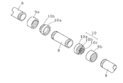
図2は本発明の実施の形態1における水滴噴霧用配管の分解斜視図である。
図2中、9は活性炭収納管、10は活性炭収納管9の両端に着脱自在に螺着される蓋体であり、10aは蓋体螺着部、10bは活性炭収納管接続部9a、9bが螺着される接続用螺着部、10cは蓋体10の端面に配設された網目部である。蓋体10が活性炭収納管9の両端に着脱自在に螺着されているので、容易に活性炭を交換することができる。また、蓋体10の端面に網目部10cを有しているので、粒状の活性炭を使用した場合でも、活性炭が活性炭収納管9から流れ出ることはない。なお、網目部10cは少なくとも下流側にあればよい。
なお、水滴を噴霧することは、蒸発潜熱の効果のほかに屋外熱交換器本体の周囲の温度が下がることによる冷却効率の向上も期待でき、特にビルの屋上など複数の屋外熱交換器本体が設置され、冷媒配管が集中している場所での温度上昇を低減することができる。
【0016】
以上のように実施の形態1における屋外熱交換器は構成されているので、以下の作用を有する。
(1)伝熱フィン表面に被着層を有することにより、熱伝導を悪化させることなく酸性雨等による腐蝕を防止し耐久性を向上できる。
(2)伝熱フィン表面の腐蝕を防止するので、伝熱フィンにほこりや煤塵が付着しても、雨水や噴霧ノズルの水道水による洗浄で簡単にほこりや煤塵を除去して性能を維持することができる。
(3)伝熱フィン表面に被着層を有することにより、水道水で洗浄しても水道水に含まれる塩素による腐蝕が発生せず、伝熱フィンを清浄に保つことができるので、伝熱フィン間が詰まって放熱が妨げられるのを防止して、熱効率の低下を防ぐことができる。
(4)ビル建物などのベランダや屋上に設置され、日光、雨、排気ガスなどにさらされても、被着層を備えているので、耐久性を保つことができる。
(5)伝熱フィンの被着層を印刷や塗膜によって形成しているので、製造工程が簡単で、歩留まりがよく、均一に大量生産を行うことができる。
(6)屋外熱交換器本体正面から水滴を噴霧し、伝熱フィン及びヘアピンチューブを濡らすことにより、水の蒸発潜熱を利用して、冷却効率を高めることが出来る。
(7)水を噴霧することにより、外気の温度も下がるので、冷却効率を高めることができ、ビルなどに集中的に配設されている屋外熱交換器本体周辺の温度上昇も低減することができる。
(8)給水管の管路途中に活性炭収納管を有しているので、水道水に含まれる塩素を取り除くことができ、フィンの塩蝕を防ぎ耐久性を向上させ、経年変化が少なく、長期にわたって性能を維持することができる。
(9)活性炭収納管が着脱自在であるため、活性炭を容易に交換することができ、塩素除去効果を維持することができる。
【0017】
(実施の形態2)
図3(a)は本発明の実施の形態1における屋外熱交換器の全体斜視図であり、図3(b)は図3(a)におけるA部拡大図である。
尚、実施の形態1と同様のものには同一の符号を付して説明を省略する。
図3(a)中、11は本発明の実施の形態2における屋外熱交換器の屋外熱交換器本体、11aは水滴滴下用配管、12は印刷や塗膜などの被着層を形成され縦方向に積層された伝熱フィン、13は銅製のヘアピンチューブ、14は合成樹脂製や金属製の散水管、15は散水管14の伝熱フィン12の対向側に形成された直径が約0.5mm〜1.0mmの散水孔、16は水栓バルブである。
図3(b)中、伝熱フィン12にはアルミ板12aの上面に厚さが約0.05μm〜20μmの被着層12bが形成されている。
水滴滴下用配管11aを流れる水は、矢印で示すように上流側から給水管8、活性炭収納管9、分岐7、散水管14を通って散水管14に穿設された散水孔15へと達する。バルブ16を開くことにより、散水孔15から伝熱フィン12に対して水を滴下する。
【0018】
以上のように実施の形態2における屋外熱交換器は構成されているので、実施の形態1に加え、以下の作用を有する。
(1)散水管に散水孔を穿孔し、伝熱フィンに水を滴下するという簡単な構成により、水の蒸発潜熱を利用して冷却効率を高めることができる。
(2)水を滴下するので、噴霧に比べて風などの影響を受け難く、より確実に伝熱フィンを濡らして、水の蒸発潜熱を利用して冷却効率を高めることができる。
【0019】
【実施例】
以下、本発明の実施例を説明する。
(実施例1)
表面に印刷層を有するアルミ缶を横2cm、縦8cmに切断したアルミ板を10枚準備し、ヘアピンチューブ3用の孔を開けて10箇所屋外熱交換器本体に取り付けた。
管路途中に活性炭を収納した散水用配管を伝熱フィンの配設部に対向するように配設し、塩素を除去した水道水を散水し続けたところ、5年後でも腐蝕が発生しないことが分かった。
また、通常使用において10年後でも腐蝕が発生しないことが分かった。
(実施例2)
家庭用クーラーの屋外熱交換器本体の伝熱フィンにスプレーで銀塗膜を形成したものと、実施例1と同サイズのアルミ板5枚を屋外熱交換器本体に取り付けたものに対し、袋状の活性炭を収納した管路を通して塩素を除去した水を噴霧しながら使用した。
1年後ではどちらにも腐蝕は発生せず、2年後では銀塗膜を形成したものに若干の腐蝕が発生したが、印刷層を有するアルミ板には腐蝕が発生しないことが分かった。
また、袋状の活性炭は購入や取り扱いが容易で、簡便に交換することができた。
(比較例)
印刷や塗膜を有さないアルミ板を伝熱フィンとして用い、同一条件で運転したところ、約3ヵ月で黒点が生じ、約3年で伝熱フィン間の詰まりが発生して熱効率が低下した。なお、沿岸付近に設置したものは、約6年で腐蝕してボロボロになった。
(実施例3)
図4に実施例3における屋外熱交換器本体及び水滴噴霧用配管の配置を示す全体平面図を示す。
図中、21は屋上に配置された屋外熱交換器本体、21aはファン、22は水滴噴霧用配管である。屋外熱交換器本体21はそれぞれ約3.75〜15kwの出力を有する空冷式冷凍機に接続され、屋外熱交換器本体21のヘアピンチューブ(図示せず)は冷媒配管(図示せず)と接続されている。
アルミ製の伝熱フィンにスプレー式の銀塗膜を3回吹き付け、これらの屋外熱交換器本体に対して、直径約100mm、長さ約600mmのパイプに収納した活性炭によって塩素を除去した水を噴霧した。
その結果、消費電力として月に約4万kw、年間で約40万kwが節約でき、電気代として約1千万円を節約できることが分かった。
1年後の点検でもアルミ製の伝熱フィンに腐蝕は発生しておらず、また、活性炭は2年間、有効に作用することが分かった。
【0020】
【発明の効果】
以上のように、本発明の屋外熱交換器によれば、以下のような有利な効果が得られる。
請求項1に記載の発明によれば、以下のような効果を有する。
(1)伝熱フィン表面に被着層を有することにより、熱伝導を悪化させることなく酸性雨等による腐蝕を防止し耐久性を向上できる信頼性、耐久性に優れる屋外熱交換器を提供することができる。
(2)伝熱フィン表面の腐蝕を防止するので、伝熱フィンにほこりや煤塵が付着しても、雨水や噴霧ノズルの水道水による洗浄で簡単にほこりや煤塵を除去して性能を維持することができる信頼性、メンテナンス性に優れる屋外熱交換器を提供することができる。
(3)伝熱フィン表面に被着層を有することにより、水道水で洗浄しても水道水に含まれる塩素による腐蝕が発生せず、伝熱フィンを清浄に保つことができるので、伝熱フィン間が詰まって放熱が妨げられるのを防止して、熱効率の低下を防ぐことができる信頼性、メンテナンス性に優れる屋外熱交換器を提供することができる。
(4)ビル建物などのベランダや屋上に設置され、日光、雨、排気ガスなどにさらされても、被着層を備えているので、耐久性を保つことができる信頼性、耐久性に優れる屋外熱交換器を提供することができる。
(5)屋外熱交換器本体正面から水滴を噴霧し、伝熱フィン及びヘアピンチューブを濡らすことにより、水の蒸発潜熱を利用して、冷却効率を高めることが出来る省エネルギー性に優れる屋外熱交換器を提供することができる。
(6)屋外熱交換器本体の伝熱フィン表面に被着層を有することにより、水道水を噴霧しても水道水に含まれる塩素によるフィンの腐蝕が発生しないので、水道に連設した噴霧ノズルを追加するだけで容易に冷却効率を高めることが出来る信頼性、省エネルギー性に優れる屋外熱交換器を提供することができる。
(7)雨水や噴霧ノズルから噴霧する水を利用して屋外熱交換器本体の洗浄を行うことができ、屋外熱交換器本体の性能を維持することができる信頼性、メンテナンス性に優れる屋外熱交換器を提供することができる。
(8)水を噴霧することにより、外気の温度も下がるので、冷却効率を高めることができる省エネルギー性に優れる屋外熱交換器を提供することができる。
(9)被着層を印刷で形成することにより、製造工程が簡単で、歩留まりがよく、均一に大量生産を行うことができる。
(10)熱硬化型(焼付け乾燥型)のインキとしてエポキシ系の一液加熱硬化型のものを用いた場合、施工性に優れ、被着強度にも優れるので、プレスや曲げなどの二次加工を行っても良好な被着層を形成することができる。
(11)被着層として塗膜を形成する場合は、スプレー式のものを用いることにより安価で容易に施工することができる。
(12)印刷と塗膜のいずれの場合も、色を白や銀にすることにより、光や熱などを吸収し難いので放熱効率が向上し、装置の外観とも合わせることができる。
(13)給水管の管路途中に活性炭収納管を有しているので、水道水に含まれる塩素を取り除くことができ、フィンの塩蝕を防ぎ耐久性を向上させ、経年変化が少なく、長期にわたって性能を維持することができる信頼性、耐久性に優れる屋外熱交換器を提供することができる。
(14)活性炭収納管が着脱自在であるため、活性炭を容易に交換することができ、塩素除去効果を維持することができる信頼性、メンテナンス性に優れる屋外熱交換器を提供することができる。
【0021】
請求項2に記載の発明によれば、請求項1の効果に加え、以下のような効果を有する。
(1)散水管に散水孔を穿孔し、伝熱フィンに水を滴下するという簡単な構成により、水の蒸発潜熱を利用して冷却効率を高めることができる施工性、省エネルギー性に優れる屋外熱交換器を提供することができる。
(2)水を滴下するので、噴霧に比べて風などの影響を受け難く、より確実に伝熱フィンを濡らして、水の蒸発潜熱を利用して冷却効率を高めることができる施工性、省エネルギー性に優れる屋外熱交換器を提供することができる。
【0023】
請求項3に記載の発明によれば、請求項1又は2の効果に加え、以下のような効果を有する。
(1)光触媒性酸化物の光触媒作用により、シリコーン樹脂またはシリカを親水化して伝熱フィン表面を親水性にして、疎水性成分を多く含む大気中の煤煙などの汚れを付着し難くし、また、付着した汚れを容易に除去することができる。
【0025】
【図面の簡単な説明】
【図1】(a)本発明の実施の形態1における屋外熱交換器の一部破断全体斜視図
(b)図1(a)におけるA部拡大図
【図2】本発明の実施の形態1における水滴噴霧用配管の分解斜視図
【図3】(a)本発明の実施の形態2における屋外熱交換器の全体斜視図
(b)図2(a)におけるB部拡大図
【図4】実施例4における屋外熱交換器本体及び水滴噴霧用配管の配置を示す全体平面図
【符号の説明】
1 屋外熱交換器本体
1a 水滴噴霧用配管
2 伝熱フィン
2a アルミ板
2b 被着層
3 ヘアピンチューブ
3a ベンド
4 ノズル部
5 通水管
6 電磁バルブ
7 分岐
8 給水管
9 活性炭収納管
9a、9b 活性炭収納管接続部
10 蓋体
10a 蓋体螺着部
10b 接続用螺着部
10c 網目部
11 屋外熱交換器本体
11a 水滴滴下用配管
12 伝熱フィン
12a アルミ板
12b 被着層
13 ヘアピンチューブ
14 散水管
15 散水孔
16 水栓バルブ
21 屋外熱交換器本体
21a ファン
22 水滴噴霧用配管[0001]
BACKGROUND OF THE INVENTION
The present invention relates to an outdoor heat exchanger used for an air-cooled refrigerator, an air conditioner, and the like, and more particularly to an outdoor heat exchanger that has stabilized cooling capacity and improved energy saving, maintenance, and durability.
[0002]
[Prior art]
Conventional outdoor heat exchangers used for air-cooled refrigerators are equipped with heat transfer fins to increase the cooling capacity of copper tubes, but aluminum plates that are suitably used as heat transfer fins are discharged from the vehicle. In addition to sulfurous acid gas, nitrogen oxidant gas, carbon dioxide gas, acid rain, etc., corrosion is likely to occur due to oxidative particulates, etc., and even in home coolers, spotted corrosion occurs in three months from the new article. Since dust and dust are likely to adhere to such a corroded portion, there is a problem that heat conduction is deteriorated and heat conduction fins are clogged to prevent heat radiation, resulting in poor heat efficiency. In addition, dust, suspended dust, dust, and the like adhering to the corroded portion of such a heat transfer fin are sticky and difficult to remove, and maintenance performance is poor, so it is difficult to maintain cooling performance.
As a result, air-cooled refrigerators such as frozen foods, refrigerated foods, chilled foods, meat, fresh fish, prepared dishes, and frozen cases used in large stores such as supermarkets have a reduced cooling capacity when the temperature rises in summer, etc. There was a problem that the bill would rise.
There are the following solutions to solve these problems.
(Patent Document 1) discloses “aluminum fin material for heat exchangers obtained by applying a surface treatment agent and a hydrophilization treatment agent to the fin material surface”.
(Patent Document 2) discloses “an air conditioner that pumps cold condensed water to a water pipe and sprays it on the fins of a heat exchanger through a nozzle”.
(Patent Document 3) “A spray nozzle that sprays water droplets on cooling air from a blower fan to a fin tube in an air-cooled heat exchanger that sends cooling air by a blower fan and cools the fluid in the fin tube in a non-contact manner. An air-cooled heat exchanger provided with the above is disclosed.
[0003]
[Patent Document 1]
JP 2002-241963 A
[Patent Document 2]
Japanese Patent Laid-Open No. 2002-5468
[Patent Document 3]
JP 2002-122387 A
[0004]
[Problems to be solved by the invention]
However, the above conventional techniques have the following problems.
In (1) (Patent Document 1), since the surface treatment agent must be applied and dried on the surface of the fin material, the hydrophilic treatment agent must be applied and dried on the surface of the surface treatment agent film. However, man-hours are required, and it is difficult to control and equalize the film thickness, resulting in poor productivity.
In (2) (Patent Document 2), the condensed water that adheres to the heat exchanger during the cooling operation and drops is collected, and is pumped to the water pipe by the pump and sprayed onto the fins of the heat exchanger through the nozzle. Condensed water can be used effectively and chlorine is not contained, so corrosion of fins can be prevented. However, it is necessary to store condensed water, the configuration is complicated, and it is difficult to add to existing heat exchangers. Had problems.
(3) (Patent Document 3) sprays water droplets on cooling air, vaporizes the water droplets on the surface of the fin tube, and attempts to cool them by the latent heat, but requires a blower fan and drives the blower fan. When water droplets adhere to electrical components such as an electric motor, there is a problem that corrosion occurs. In addition, in order to prevent adhesion of water droplets, it is necessary to control the rotation speed of the blower fan and the particle size of the water droplets, and there is a problem that the configuration is complicated and cannot be easily added to an existing heat exchanger. It was.
[0005]
The present invention solves the above-mentioned conventional problems, can improve and stabilize the cooling performance with a simple configuration, can be easily manufactured and mass-produced, has uniform quality, excellent durability, stable performance, and maintainability. An object is to provide an outdoor heat exchanger that can be obtained.
[0006]
In order to solve the above problems, the outdoor heat exchanger of the present invention has the following configuration.
The outdoor heat exchanger according to claim 1 of the present invention is(A)On one or both sidesPrinted layer or coatingA plurality of heat transfer fins made of aluminum or aluminum alloy on which a coating layer is formedOutdoor heat exchanger body withWhen,(B)A nozzle portion disposed opposite to the heat transfer fin arrangement portion and provided with a spray nozzle; a water pipe for supplying water to the nozzle portion; and a water supply pipe connected to the water pipe;An activated carbon storage pipe detachably disposed in the middle of the pipe of the water supply pipe, and a water droplet spraying pipe for spraying water droplets from the front of the outdoor heat exchanger bodyIt has the structure provided with.
This configuration has the following effects.
(1) By having an adhesion layer on the surface of the heat transfer fin, corrosion due to acid rain or the like can be prevented and durability can be improved without deteriorating heat conduction.
(2) Since corrosion of the heat transfer fin surface is prevented, even if dust or dust adheres to the heat transfer fin, the performance is maintained by simply removing dust and dust by washing with rainwater or tap water from the spray nozzle. be able to.
(3) By having an adhesion layer on the surface of the heat transfer fin, corrosion by chlorine contained in tap water does not occur even when washed with tap water, and the heat transfer fin can be kept clean. It is possible to prevent clogging between the fins and hinder heat dissipation, thereby preventing a decrease in thermal efficiency.
(4) Even if it is installed on a veranda or a rooftop of a building, etc., and is exposed to sunlight, rain, exhaust gas, etc., it has an adherent layer, so durability can be maintained.
(5) Outdoor heat exchangerBodyBy spraying water droplets from the front and wetting the heat transfer fins, the cooling efficiency can be improved by utilizing the latent heat of water evaporation.
(6) Outdoor heat exchangerBodyBy having an adhesion layer on the surface of the heat transfer fins, corrosion of fins due to chlorine contained in tap water does not occur even when tap water is sprayed, so it is easy to add a spray nozzle connected to the tap water. Cooling efficiency can be increased.
(7) The outdoor heat exchanger can be cleaned using water sprayed from the spray nozzle, and the performance of the outdoor heat exchanger can be maintained.
(8) Since the temperature of the outside air is lowered by spraying water, the cooling efficiency can be increased and the outdoor heat exchanger that is intensively arranged in a building or the likeBodyA rise in ambient temperature can also be reduced.
(9) By forming the adherent layer by printing, the manufacturing process is simple, the yield is good, and mass production can be performed uniformly.
(10) When an epoxy one-component heat curing ink is used as the thermosetting (baking and drying) ink, it is excellent in workability and adherence strength, so secondary processing such as pressing and bending. Even if it performs, a favorable deposit layer can be formed.
(11) When a coating film is formed as the adherent layer, it can be easily applied at low cost by using a spray type.
(12) In both cases of printing and coating, by making the color white or silver, it is difficult to absorb light or heat, so that the heat dissipation efficiency is improved and the appearance of the apparatus can be matched.
(13) Since it has an activated carbon storage pipe in the middle of the pipe of the water supply pipe, it can remove chlorine contained in tap water, prevent salt corrosion of fins, improve durability, have little secular change, long-term Performance can be maintained over time.
(14) Since the activated carbon storage tube is detachable, the activated carbon can be easily replaced and the chlorine removal effect can be maintained.
[0007]
Here, examples of the deposition layer formed on the surface of the heat transfer fin include a printing layer and a coating film.
In the case of printing, offset printing or screen printing generally performed on aluminum cans or other metal plates is suitable. By forming the deposition layer by printing, the manufacturing process is simple, the yield is good, and mass production can be performed uniformly.
In the case of screen printing, pressure film printing corresponding to a
In addition, types of ink used for screen printing include solvent drying type, reaction curing type, thermosetting type (baking drying type), etc., but smoothness, adhesion, weather resistance, water resistance, chemical resistance A thermosetting type (baking and drying type) having excellent durability is suitable. As the thermosetting (baking and drying) ink, an epoxy one-component heat-curable ink is preferable. Since it is a one-component heat-curing type, it has excellent workability and excellent adhesion strength, so that a good adhesion layer can be formed even if secondary processing such as pressing or bending is performed.
When a coating film is formed as the adherent layer, a spray type is preferable. Thereby, it can be constructed inexpensively and easily.
In both cases of printing and coating, the color is preferably white or silver. Thereby, since it is difficult to absorb light, heat, etc., heat dissipation efficiency improves, and it can match with the appearance of the apparatus.
[0008]
When using an aluminum plate as a heat transfer fin, it is desirable to first print on a flat aluminum plate and then drill a through hole through which the hairpin tube is inserted. Thereby, a good deposition layer can be formed.
As a method of closely attaching the heat transfer fin and the hairpin tube, the inner diameter of the through hole formed in the heat transfer fin is processed to be larger than the outer shape of the hairpin tube, and after inserting the hairpin tube into the heat transfer fin, mechanically There are a method in which the hairpin tube is expanded and brought into close contact with the heat transfer fin, and a method in which the inner diameter of the through hole formed in the heat transfer fin is made smaller than the outer shape of the hairpin tube and the heat transfer fin is press-fitted.
A copper, stainless steel, or iron tube is preferably used as the hairpin tube, and is reciprocated between the laminated heat transfer fins in a zigzag manner and connected to one. A copper, stainless steel, or iron tube is preferably used for the U-shaped bend connected to the end to connect the hairpin tubes into one.
The heat transfer fins are laminated in a horizontal direction and a vertical direction. In the case of the horizontal direction, the deposited layer may be at least on the upper surface side after lamination. It is desirable to have a layer. This effectively protects the heat transfer fins from dirt such as smoke.
[0009]
A pipe made of synthetic resin or metal is used for the pipe from the tap water supply source to the spray nozzle. It is desirable to use a pipe made of synthetic resin or the like for the water supply pipe from the tap water supply source to the vicinity of the heat exchanger. Thereby, since it is excellent in workability and workability, installation is easy, and the flow rate can be ensured by thickening the pipeline. Further, a water pipe is provided in the middle of the water supply pipe by a trifurcation or the like, and a water pipe to the front of the heat exchanger to which the spray nozzle is connected is disposed.
By using a copper pipe for the water flow pipe, a flare joint with reliable connection can be used, and water leakage and the like can be reliably prevented. The inner diameter of the water pipe is preferably about 2 mm to 6 mm. If the inner diameter is thinner than 2 mm, a sufficient flow rate cannot be obtained, and if the inner diameter is larger than 6 mm, the water pressure tends to be low and the entire heat exchanger cannot be sprayed. Spraying to about 10 heat exchangers with an inner diameter of about 4 mm is possible.
At this time, the spray amount is preferably about 2 L to 3 L per one outdoor heat exchanger per hour. If the amount of spray is less than 2L, the effect of latent heat of vaporization is reduced. .
[0010]
A valve may be disposed between the spray nozzle and the water pipe. Thereby, the start and stop of spraying can be switched for each heat exchanger, and unnecessary consumption of water can be prevented. The valve may be an electromagnetic valve instead of manual operation. Thereby, the start and stop of spraying, control of pressure, flow rate, and the like can be easily performed.
Furthermore, when spraying simultaneously with respect to several heat exchangers, you may install a water supply tank and spray by pressurizing water with a compressor. Thereby, while reducing the amount of water, it can spray efficiently over a wide range.
Examples of the raw material of the activated carbon stored in the activated carbon storage pipe include sawdust, charcoal, peat, coal, coconut shell, etc., but it is desirable to use a coconut shell having a large specific surface area. Thereby, it is excellent in dechlorination property. The granular activated carbon is preferably contained in a water-permeable bag. At this time, it is desirable to provide a mesh-like lid body at least on the downstream side of the activated carbon storage tube, which makes it easy to handle and can be easily purchased and replaced. Moreover, as a shape of activated carbon, a granular thing may be sufficient, but a fibrous thing and a secondary processed product may be used. By using a fibrous material, not only is it difficult for water to pass through and clogging, but because the fibers are stacked alternately in the vertical and horizontal directions, it is efficient because water passes uniformly and there is little loss of water pressure. .
In addition, since the secondary processed product processed into a filter shape or a cartridge shape is easy to handle and can be easily attached to and detached from the activated carbon storage tube, it can be used more suitably.
By providing detachable mesh-like lids at both ends of the activated carbon storage tube, the activated carbon in the activated carbon storage tube can be easily replaced and held. Further, since the activated carbon storage pipe is detachably disposed in the middle of the pipeline by a method such as screwing, the entire activated carbon storage pipe in which the activated carbon is previously stored may be replaced.
[0011]
The outdoor heat exchanger according to
With this configuration, in addition to the operation obtained in the first aspect, the following operation can be obtained.
(1) With a simple configuration in which watering holes are drilled in the watering pipe and water is dropped on the heat transfer fins, the cooling efficiency can be increased by utilizing the latent heat of water evaporation.
(2) Since water is dripped, it is less susceptible to wind and the like than spraying, and the heat transfer fins can be wetted more reliably, and the cooling efficiency can be increased by utilizing the latent heat of water evaporation.
Here, as the water spray pipe, a pipe made of synthetic resin or copper, stainless steel, brass or the like can be used. A watering hole having a diameter of about 0.5 mm to 2.5 mm, preferably about 0.5 mm to 1.0 mm is drilled in this. If the diameter of the sprinkling hole is smaller than 0.5 mm, the amount of water is small and the entire fin cannot be wetted, so that sufficient latent heat of vaporization cannot be used. As the diameter becomes larger than 1.0 mm, the amount of water is too large. The utilization efficiency of latent heat of vaporization is lowered, and there is a tendency that a sufficient effect cannot be obtained.
Outdoor heat exchangerBodyIf there are many units and refrigerant pipes are concentrated, sprinkling holes may be formed in the water supply pipes or water pipes branched in the middle of the water supply pipes to sprinkle the refrigerant pipes to reduce the heat quantity of the refrigerant. Good. Thereby, cooling efficiency can be improved.
[0013]
Of the present inventionClaim 3The outdoor heat exchanger described inClaim 1 or 2It has the structure by which the surface layer containing a photocatalytic oxide and a silicone resin or a silica is formed in the surface of the said adherence layer.
With this configuration,Claim 1 or 2In addition to the above action, it has the following action.
(1) The photocatalytic action of the photocatalytic oxide makes the surface of the heat transfer fin hydrophilic by making the silicone resin or silica hydrophilic, making it difficult to attach dirt such as smoke in the atmosphere containing a large amount of hydrophobic components. The adhered dirt can be easily removed.
Here, the amount of the photocatalytic oxide in the surface layer is preferably about 10 to 80% by weight, and more preferably about 20 to 50% by weight. When the surface of the heat transfer fin is irradiated with light, hydrophilicity is imparted to silicone and silica by the action of the photocatalytic oxide present in the surface layer, and this hydrophilicity lasts as long as the light irradiation is continued. Furthermore, even if light irradiation is stopped once, when light is irradiated again, hydrophilicity is imparted again. In addition, since the photocatalytic oxide decomposes contaminants, the surface of the heat transfer fin can be prevented from being soiled and kept clean.
[0015]
DETAILED DESCRIPTION OF THE INVENTION
Hereinafter, an outdoor heat exchanger according to an embodiment of the present invention will be described with reference to the drawings.
(Embodiment 1)
FIG. 1A is a partially broken overall perspective view of an outdoor heat exchanger according to Embodiment 1 of the present invention, and FIG. 1B is an enlarged view of a portion A in FIG.
In FIG. 1 (a), reference numeral 1 denotes an outdoor heat exchanger according to Embodiment 1 of the present invention.Outdoor heat exchanger body1a is a water droplet spraying pipe, 2 is an outdoor heat exchangerBody1 is a heat transfer fin in which a copper hairpin tube is fitted into the opening and a large number of the hairpin tubes are arranged side by side, and an adherence layer such as a printing or coating film is formed on the surface thereof; 3 is a copper hairpin tube; 3a is a
In FIG. 1B, the
Outdoor heat exchangerBody1 is formed of a
The water flowing through the water droplet spraying pipe 1a reaches the
Next, the activated
FIG. 2 is an exploded perspective view of the water droplet spraying pipe according to Embodiment 1 of the present invention.
In FIG. 2, 9 is an activated carbon storage tube, 10 is a lid that is detachably screwed to both ends of the activated
In addition to the effect of latent heat of evaporation, spraying water droplets is an outdoor heat exchanger.BodyThe cooling efficiency can be expected to be improved by lowering the ambient temperature of the building.BodyThe temperature rise in the place where refrigerant piping is concentrated can be reduced.
[0016]
Since the outdoor heat exchanger in Embodiment 1 is configured as described above, it has the following effects.
(1) By having an adhesion layer on the surface of the heat transfer fin, corrosion due to acid rain or the like can be prevented and durability can be improved without deteriorating heat conduction.
(2) Since corrosion of the heat transfer fin surface is prevented, even if dust or dust adheres to the heat transfer fin, the performance is maintained by simply removing dust and dust by washing with rainwater or tap water from the spray nozzle. be able to.
(3) By having an adhesion layer on the surface of the heat transfer fin, corrosion by chlorine contained in tap water does not occur even when washed with tap water, and the heat transfer fin can be kept clean. It is possible to prevent clogging between the fins and hinder heat dissipation, thereby preventing a decrease in thermal efficiency.
(4) Even if it is installed on a veranda or a rooftop of a building, etc., and is exposed to sunlight, rain, exhaust gas, etc., it has an adherent layer, so durability can be maintained.
(5) Since the adherence layer of the heat transfer fin is formed by printing or a coating film, the manufacturing process is simple, the yield is good, and mass production can be performed uniformly.
(6) Outdoor heat exchangerBodyBy spraying water droplets from the front and wetting the heat transfer fins and the hairpin tube, it is possible to increase the cooling efficiency by utilizing the latent heat of vaporization of water.
(7) Since the temperature of the outside air is lowered by spraying water, the cooling efficiency can be increased, and the outdoor heat exchanger that is concentrated in the building or the likeBodyA rise in ambient temperature can also be reduced.
(8) Since it has an activated carbon storage pipe in the middle of the pipe of the water supply pipe, chlorine contained in tap water can be removed, salt corrosion of fins is prevented, durability is improved, secular change is small, and long-term Performance can be maintained over time.
(9) Since the activated carbon storage tube is detachable, the activated carbon can be easily replaced, and the chlorine removal effect can be maintained.
[0017]
(Embodiment 2)
FIG. 3A is an overall perspective view of the outdoor heat exchanger according to Embodiment 1 of the present invention, and FIG. 3B is an enlarged view of a portion A in FIG.
In addition, the same code | symbol is attached | subjected to the thing similar to Embodiment 1, and description is abbreviate | omitted.
In FIG. 3A, 11 is an outdoor heat exchanger according to
In FIG. 3B, the
The water flowing through the water
[0018]
As described above, the outdoor heat exchanger in the second embodiment is configured, and thus has the following action in addition to the first embodiment.
(1) With a simple configuration in which watering holes are drilled in the watering pipe and water is dropped on the heat transfer fins, the cooling efficiency can be increased by utilizing the latent heat of water evaporation.
(2) Since water is dripped, it is less susceptible to wind and the like than spraying, and the heat transfer fins can be wetted more reliably, and the cooling efficiency can be increased by utilizing the latent heat of water evaporation.
[0019]
【Example】
Examples of the present invention will be described below.
Example 1
Prepare 10 aluminum plates cut into 2cm wide and 8cm long aluminum cans with printed layer on the surface, open holes for
When watering pipes containing activated carbon are placed in the middle of the pipe so that they face the heat transfer fins, and water is continuously sprinkled with tap water from which chlorine has been removed, no corrosion will occur even after 5 years. I understood.
It was also found that no corrosion occurred even after 10 years in normal use.
(Example 2)
Home cooler outdoor heat exchangerBodyA heat transfer fin with a silver coating formed by spraying and five aluminum plates of the same size as in Example 1 were used as outdoor heat exchangers.BodyIn addition to the one attached to, the water from which chlorine was removed was sprayed through a pipe line containing bag-like activated carbon.
After 1 year, no corrosion occurred in either, and after 2 years, some corrosion occurred on the silver coating film, but no corrosion occurred on the aluminum plate with the printed layer.
In addition, bag-like activated carbon was easy to purchase and handle and could be easily replaced.
(Comparative example)
When an aluminum plate without printing or coating was used as heat transfer fins and operated under the same conditions, black spots occurred in about 3 months, and clogging between heat transfer fins occurred in about 3 years, resulting in a decrease in thermal efficiency. . In addition, what was installed near the coast was corroded in about 6 years.
(Example 3)
FIG. 4 shows an outdoor heat exchanger in Example 3.BodyAnd the whole top view which shows arrangement | positioning of piping for water droplet spraying is shown.
In the figure, 21 is an outdoor heat exchanger arranged on the rooftop.Body, 21a is a fan, and 22 is a water droplet spraying pipe. Outdoor heat exchangerBody21 are each connected to an air-cooled refrigerator having an output of about 3.75 to 15 kw, and an outdoor heat exchangerBodyA hairpin tube 21 (not shown) is connected to a refrigerant pipe (not shown).
Spray heat spray fins on aluminum
As a result, it was found that about 40,000 kw per month can be saved as power consumption and about 400,000 kw per year, and about 10 million yen can be saved as electricity bill.
One year after inspection, it was found that the aluminum heat transfer fins were not corroded, and that the activated carbon worked effectively for two years.
[0020]
【The invention's effect】
As described above, according to the outdoor heat exchanger of the present invention, the following advantageous effects can be obtained.
According to invention of Claim 1, it has the following effects.
(1) To provide an outdoor heat exchanger with excellent reliability and durability that can prevent corrosion due to acid rain and the like and improve durability without deteriorating heat conduction by having an adhesion layer on the surface of the heat transfer fin. be able to.
(2) Since corrosion of the heat transfer fin surface is prevented, even if dust or dust adheres to the heat transfer fin, the performance is maintained by simply removing dust and dust by washing with rainwater or tap water from the spray nozzle. It is possible to provide an outdoor heat exchanger with excellent reliability and maintainability.
(3) By having an adhesion layer on the surface of the heat transfer fin, corrosion by chlorine contained in tap water does not occur even when washed with tap water, and the heat transfer fin can be kept clean. It is possible to provide an outdoor heat exchanger with excellent reliability and maintainability that can prevent the heat radiation from being blocked due to clogging between the fins and prevent a decrease in thermal efficiency.
(4) It is installed on a veranda or rooftop of a building, etc., and has an adherent layer even when exposed to sunlight, rain, exhaust gas, etc., so it has excellent reliability and durability that can maintain durability. An outdoor heat exchanger can be provided.
(5) Outdoor heat exchangerBodyBy spraying water droplets from the front and wetting the heat transfer fins and the hairpin tube, it is possible to provide an outdoor heat exchanger excellent in energy saving that can improve the cooling efficiency by utilizing the latent heat of evaporation of water.
(6) Outdoor heat exchangerBodyBy having an adhesion layer on the surface of the heat transfer fins, corrosion of fins due to chlorine contained in tap water does not occur even when tap water is sprayed, so it is easy to add a spray nozzle connected to the tap water. It is possible to provide an outdoor heat exchanger that can improve cooling efficiency and is excellent in reliability and energy saving.
(7) Outdoor heat exchanger using rainwater or water sprayed from spray nozzleBodyCan be cleaned of outdoor heat exchangerBodyIt is possible to provide an outdoor heat exchanger that can maintain the performance of the present invention and is excellent in reliability and maintainability.
(8) Since the temperature of the outside air is lowered by spraying water, it is possible to provide an outdoor heat exchanger excellent in energy saving that can improve the cooling efficiency.
(9) By forming the adherent layer by printing, the manufacturing process is simple, the yield is good, and mass production can be performed uniformly.
(10) When an epoxy one-component heat curing ink is used as the thermosetting (baking and drying) ink, it is excellent in workability and adherence strength, so secondary processing such as pressing and bending. Even if it performs, a favorable deposit layer can be formed.
(11) When a coating film is formed as the adherent layer, it can be easily applied at low cost by using a spray type.
(12) In both cases of printing and coating, by making the color white or silver, it is difficult to absorb light or heat, so that the heat dissipation efficiency is improved and the appearance of the apparatus can be matched.
(13) Since it has an activated carbon storage pipe in the middle of the pipe of the water supply pipe, chlorine contained in tap water can be removed, salt corrosion of fins is prevented, durability is improved, secular change is small, and long-term It is possible to provide an outdoor heat exchanger excellent in reliability and durability capable of maintaining performance over a wide range.
(14) Since the activated carbon storage tube is detachable, it is possible to provide an outdoor heat exchanger that can easily replace the activated carbon and maintain the chlorine removal effect and is excellent in reliability and maintainability.
[0021]
According to invention of
(1) Outdoor heat that excels in workability and energy saving, which can increase the cooling efficiency by using the latent heat of water evaporation, with a simple configuration of perforating holes in the water spray pipe and dropping water into the heat transfer fins. An exchanger can be provided.
(2) Since water is dripped, compared to spraying, it is less susceptible to wind and other factors, so that heat transfer fins can be wetted more reliably and the cooling efficiency can be improved by using the latent heat of water evaporation. It is possible to provide an outdoor heat exchanger that is excellent in performance.
[0023]
Claim 3According to the invention described inClaim 1 or 2In addition to the above effects, the following effects are obtained.
(1) The photocatalytic action of the photocatalytic oxide makes the surface of the heat transfer fin hydrophilic by making the silicone resin or silica hydrophilic, making it difficult to attach dirt such as smoke in the atmosphere containing a large amount of hydrophobic components. The adhered dirt can be easily removed.
[0025]
[Brief description of the drawings]
FIG. 1 (a) is a partially broken overall perspective view of an outdoor heat exchanger according to Embodiment 1 of the present invention.
(B) Enlarged view of part A in FIG.
FIG. 2 is an exploded perspective view of a water droplet spray pipe according to Embodiment 1 of the present invention.
3A is an overall perspective view of an outdoor heat exchanger according to
(B) Enlarged view of part B in FIG.
FIG. 4 shows an outdoor heat exchanger in Example 4BodyAnd overall plan view showing the arrangement of piping for water droplet spraying
[Explanation of symbols]
1 Outdoor heat exchangerBody
1a Piping for water droplet spraying
2 Heat transfer fins
2a Aluminum plate
2b Adhering layer
3 Hairpin tubes
3a bend
4 Nozzle part
5 water pipe
6 Solenoid valve
7 branch
8 Water supply pipe
9 Activated carbon storage tube
9a, 9b Activated carbon storage pipe connection
10 Lid
10a Lid screw part
10b Connection threaded part
10c mesh part
11 Outdoor heat exchangerBody
11a Water drop dripping piping
12 Heat transfer fins
12a Aluminum plate
12b Deposited layer
13 Hairpin tube
14 Watering pipe
15 Watering hole
16 Faucet valve
21 Outdoor heat exchangerBody
21a fan
22 Water droplet spray piping
Claims (3)
Priority Applications (2)
| Application Number | Priority Date | Filing Date | Title |
|---|---|---|---|
| JP2003060502A JP3707737B2 (en) | 2003-03-06 | 2003-03-06 | Outdoor heat exchanger |
| CNA2003101242669A CN1526996A (en) | 2003-03-06 | 2003-12-29 | Outdoor heat exchanger |
Applications Claiming Priority (1)
| Application Number | Priority Date | Filing Date | Title |
|---|---|---|---|
| JP2003060502A JP3707737B2 (en) | 2003-03-06 | 2003-03-06 | Outdoor heat exchanger |
Publications (3)
| Publication Number | Publication Date |
|---|---|
| JP2004271008A JP2004271008A (en) | 2004-09-30 |
| JP2004271008A5 JP2004271008A5 (en) | 2005-09-08 |
| JP3707737B2 true JP3707737B2 (en) | 2005-10-19 |
Family
ID=33123023
Family Applications (1)
| Application Number | Title | Priority Date | Filing Date |
|---|---|---|---|
| JP2003060502A Expired - Fee Related JP3707737B2 (en) | 2003-03-06 | 2003-03-06 | Outdoor heat exchanger |
Country Status (2)
| Country | Link |
|---|---|
| JP (1) | JP3707737B2 (en) |
| CN (1) | CN1526996A (en) |
Families Citing this family (10)
| Publication number | Priority date | Publication date | Assignee | Title |
|---|---|---|---|---|
| JP2013079735A (en) * | 2011-09-30 | 2013-05-02 | Daikin Industries Ltd | Outdoor unit and refrigerating device |
| JP5641004B2 (en) * | 2012-03-16 | 2014-12-17 | 三菱電機株式会社 | Refrigeration cycle equipment |
| CN104677181B (en) * | 2013-11-26 | 2017-01-04 | 北京中矿博能节能科技有限公司 | There is the weary wind heat-exchanger rig of automatic clearing apparatus |
| JP6320071B2 (en) * | 2014-02-18 | 2018-05-09 | 大阪瓦斯株式会社 | Air conditioning system and heat exchange device |
| CN106871271B (en) * | 2017-03-31 | 2019-07-19 | 美的集团武汉制冷设备有限公司 | The cleaning device and air conditioner of heat exchanger of air conditioner outdoor unit |
| CN107327919A (en) * | 2017-07-14 | 2017-11-07 | 广东美的制冷设备有限公司 | Indoor apparatus of air conditioner and air-conditioning |
| CN108131743B (en) * | 2018-01-09 | 2024-03-22 | 珠海格力电器股份有限公司 | Heat exchanger water drenching device, air conditioner outdoor unit and air conditioner |
| JP2020186819A (en) * | 2019-05-09 | 2020-11-19 | スミコーホームズ株式会社 | Groundwater utilization type heat exchanger and airconditioning system using the same |
| CN111609558B (en) * | 2020-05-15 | 2022-01-07 | 华帝股份有限公司 | Method for preventing water pipe from being corroded and water heater using same |
| CN113551335B (en) * | 2021-07-21 | 2022-09-13 | 珠海格力电器股份有限公司 | Air conditioner |
Family Cites Families (9)
| Publication number | Priority date | Publication date | Assignee | Title |
|---|---|---|---|---|
| JPS5843736Y2 (en) * | 1979-04-11 | 1983-10-03 | 松下電器産業株式会社 | air conditioner |
| JPS59161475U (en) * | 1984-03-29 | 1984-10-29 | 松下電器産業株式会社 | air conditioner |
| JPH0762571B2 (en) * | 1990-11-08 | 1995-07-05 | 東邦瓦斯株式会社 | Air-cooled radiator for refrigeration cycle |
| JPH05104081A (en) * | 1991-10-15 | 1993-04-27 | Yamashin Kogyo Kk | Water purifier unit |
| JPH05125750A (en) * | 1991-11-05 | 1993-05-21 | Ebara Corp | Water purifying plant and method |
| JPH05223364A (en) * | 1992-02-06 | 1993-08-31 | Yazaki Corp | Air cooling heat radiation apparatus of freezing cycle |
| JPH09231821A (en) * | 1995-12-22 | 1997-09-05 | Toto Ltd | Luminaire and method for maintaining illuminance |
| JP2000179993A (en) * | 1998-12-16 | 2000-06-30 | Matsushita Electric Ind Co Ltd | Heat exchanger for air conditioner |
| JP2002039567A (en) * | 2000-07-28 | 2002-02-06 | Toshiba Plant Kensetsu Co Ltd | Air conditioner and its operation method |
-
2003
- 2003-03-06 JP JP2003060502A patent/JP3707737B2/en not_active Expired - Fee Related
- 2003-12-29 CN CNA2003101242669A patent/CN1526996A/en active Pending
Also Published As
| Publication number | Publication date |
|---|---|
| JP2004271008A (en) | 2004-09-30 |
| CN1526996A (en) | 2004-09-08 |
Similar Documents
| Publication | Publication Date | Title |
|---|---|---|
| JP3707737B2 (en) | Outdoor heat exchanger | |
| EP3379152B1 (en) | Cooking appliance and method of conveying heat energy from a cooking exhaust hood | |
| US7805953B2 (en) | Prefilter system for heat transfer unit and method | |
| CN104197588B (en) | A kind of composite construction wet film surface cooler | |
| US3052105A (en) | Heat exchanger | |
| CN108709341A (en) | A kind of pre- cold mould spray evaporation type condenser | |
| CN2144287Y (en) | Closed cooling tower | |
| CN109224727A (en) | A kind of board-like cloud cooperation-removal flue gas condenser | |
| CN209978257U (en) | Intelligent atomization spraying device | |
| JP2010151363A (en) | Sealed type cooling apparatus | |
| CN2821464Y (en) | Air conditioner with condensation using device | |
| CN2556571Y (en) | Counterflow evaporative condenser | |
| CN213713311U (en) | Heat pump air conditioner outdoor heat exchanger cleaning device based on super-hydrophobic | |
| CN114141484A (en) | High heat exchange efficiency air cooler suitable for strong corrosive environment | |
| CN111212204B (en) | Energy-saving camera based on block chain technology | |
| CN210070651U (en) | Closed heat exchange equipment of dry-wet integrated tube bundle | |
| CN202793071U (en) | Scale formation-resistant and freezing-resistant closed cooling tower | |
| CN220229637U (en) | Refrigeration system for preventing scaling outside condenser tube | |
| CN206410379U (en) | A kind of condensing unit | |
| CN219433913U (en) | Evaporation type condenser with water collector cleaning device | |
| CN205332835U (en) | Evaporation precooling formula air cooler | |
| CN220269609U (en) | Novel automatic sprinkling energy-saving device of air-cooled air conditioner | |
| CN217383367U (en) | Evaporator of low-temperature corrosion-resistant swimming pool dehumidifying unit | |
| CN211836323U (en) | Negative pressure multiple-effect evaporation device for treating nickel and phosphorus plating waste liquid | |
| CN209804840U (en) | Lithium battery pyrolysis equipment and electromagnetic coil cooling system thereof |
Legal Events
| Date | Code | Title | Description |
|---|---|---|---|
| A621 | Written request for application examination |
Free format text: JAPANESE INTERMEDIATE CODE: A621 Effective date: 20041112 |
|
| A521 | Written amendment |
Free format text: JAPANESE INTERMEDIATE CODE: A523 Effective date: 20050311 |
|
| A871 | Explanation of circumstances concerning accelerated examination |
Free format text: JAPANESE INTERMEDIATE CODE: A871 Effective date: 20050311 |
|
| A975 | Report on accelerated examination |
Free format text: JAPANESE INTERMEDIATE CODE: A971005 Effective date: 20050407 |
|
| A131 | Notification of reasons for refusal |
Free format text: JAPANESE INTERMEDIATE CODE: A131 Effective date: 20050414 |
|
| A521 | Written amendment |
Free format text: JAPANESE INTERMEDIATE CODE: A523 Effective date: 20050613 |
|
| TRDD | Decision of grant or rejection written | ||
| A01 | Written decision to grant a patent or to grant a registration (utility model) |
Free format text: JAPANESE INTERMEDIATE CODE: A01 Effective date: 20050706 |
|
| A61 | First payment of annual fees (during grant procedure) |
Free format text: JAPANESE INTERMEDIATE CODE: A61 Effective date: 20050729 |
|
| R150 | Certificate of patent or registration of utility model |
Free format text: JAPANESE INTERMEDIATE CODE: R150 |
|
| S111 | Request for change of ownership or part of ownership |
Free format text: JAPANESE INTERMEDIATE CODE: R313113 |
|
| R360 | Written notification for declining of transfer of rights |
Free format text: JAPANESE INTERMEDIATE CODE: R360 |
|
| R370 | Written measure of declining of transfer procedure |
Free format text: JAPANESE INTERMEDIATE CODE: R370 |
|
| S111 | Request for change of ownership or part of ownership |
Free format text: JAPANESE INTERMEDIATE CODE: R313113 |
|
| R350 | Written notification of registration of transfer |
Free format text: JAPANESE INTERMEDIATE CODE: R350 |
|
| FPAY | Renewal fee payment (event date is renewal date of database) |
Free format text: PAYMENT UNTIL: 20080812 Year of fee payment: 3 |
|
| FPAY | Renewal fee payment (event date is renewal date of database) |
Free format text: PAYMENT UNTIL: 20080812 Year of fee payment: 3 |
|
| FPAY | Renewal fee payment (event date is renewal date of database) |
Free format text: PAYMENT UNTIL: 20080812 Year of fee payment: 3 |
|
| FPAY | Renewal fee payment (event date is renewal date of database) |
Free format text: PAYMENT UNTIL: 20080812 Year of fee payment: 3 |
|
| FPAY | Renewal fee payment (event date is renewal date of database) |
Free format text: PAYMENT UNTIL: 20080812 Year of fee payment: 3 |
|
| FPAY | Renewal fee payment (event date is renewal date of database) |
Free format text: PAYMENT UNTIL: 20090812 Year of fee payment: 4 |
|
| LAPS | Cancellation because of no payment of annual fees |