【0001】
【発明の属する技術分野】
本発明は、対峙して建て込まれる構造壁とこれらの上下端に建て込まれる床部材とで囲まれた空間に居住空間を構成するようになったPC部材を用いた建築構造に関する。
【0002】
【従来の技術】
建築物は柱、梁、床や壁などにPC(プレキャストコンクリート)部材を用いることにより、現場での省力化や工期の短縮化を達成することができる。従来の一般的な集合住宅はPC部材を用いた柱や梁および耐震壁で構成され、例えば図6に示す建築構造1では、各住戸A1,A2,A3…が妻方向(図中上下方向)に配置される戸境壁2によって画成される。また、この建築構造1では梁3は桁行方向(図中左右方向)のみに配置されて、当該桁行方向は柱4と梁3によるラーメン架構となり、妻方向には上記戸境壁2を耐震壁とする耐震壁架構となっている。この場合、上記建築構造1では住戸A2,A3や住戸A4,A5が妻方向にずれる、いわゆる雁行配置となっており、かつ、柱4と梁3の構面の外側にバルコニー6や廊下7が設けられている。
【0003】
【発明が解決しようとする課題】
しかしながら、柱・梁を用いた従来の建築構造1では、住戸が雁行する場合に相隣接する住戸A2,A3,A4,A5のうちいずれか一方の住戸A3,A5の梁3端部が他方の住戸A2,A4の内方に対応する位置となり、その梁3端部には余分に柱4(図中、Pで示す)が必要になって全体的な柱4の本数が増加してしまう。このため、建築費の高騰が来されるのは勿論のこと、住戸A2〜A5内の居住空間が狭められてしまう。また、上記戸境壁2には上記Pで示した柱4以外にも本来の柱4が設けられるが、これらの柱4は戸境壁2より突出して設けられることになり、該戸境壁2に沿ったスペースの有効利用を難しくしてしまう。
【0004】
そこで、本発明はかかる従来の課題に鑑みて成されたもので、構造壁自体に柱構造を組み込むことにより、柱の突出を無くして居住空間の拡充化を図るとともに、構造壁の壁面に沿ったスペースの有効利用を図ることができるPC部材を用いた建築構造を提供することを目的とする。
【0005】
【課題を解決するための手段】
かかる目的を達成するために本発明のPC部材を用いた建築構造は、一対のPC壁板間に、柱配筋と壁用ボイド型枠とを水平方向に所定間隔をもって交互に配置してコンクリートを打設することにより、上記柱配筋が埋設された壁内柱と上記壁用ボイド型枠によって形成される空洞部分とが設けられる構造壁を備え、該構造壁を対峙して建て込むとともに、これら構造壁とこれに建て込まれる床部材とで囲まれた空間に居住空間を構成することを特徴とする。
【0006】
また、上記床部材は、PC床板の上側に、上記柱配筋および上記壁用ボイド型枠の配置位置に対応させて梁配筋と床用ボイド型枠とを交互に配置してコンクリートを打設することにより、上記梁配筋が埋設される床内梁と、上記床用ボイド型枠によって形成される空洞部分とを設けて構成し、該床部材と上記構造壁との接合部分で該床内梁と上記壁内柱とを結合したことを特徴とする。
【0007】
さらに、上記構造壁と上記床部材との接合部分に、ハンチを設けたことを特徴とする。
【0008】
【発明の実施の形態】
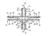
以下、本発明の実施形態を添付図面を参照して詳細に説明する。図1から図4は本発明のPC部材を用いた建築構造の一実施形態を示し、図1は構造壁と床部材とを建て込んだ状態でコンクリートの打設前を示す平面図、図2は図1中A−A線からの拡大断面図、図3は図2中B−B線からの断面図、図4は図2中C−C線からの断面図である。
【0009】
本実施形態の建築構造10は図1に示すようにユニット化された集合住宅として構成され、各住戸A1,A2,A3…は構造壁としての戸境壁11によって画成された状態で桁行方向に横並び配置されるとともに、本実施形態では住戸A1と住戸A2は妻方向にずれて雁行配置されている。上記住戸A1,A2,A3…は、対峙して建て込まれる上記戸境壁11と、これら対峙する戸境壁11間に建て込まれる床部材としての床スラブ12とで囲まれる空間を居住空間として構成される。ところで、図1は現場打ちコンクリートが打設される以前の状態を示してある。
【0010】
上記戸境壁11は、図3に示すように適宜間隔Sをもって対向配置される1対のPC壁板13を備えたダブルウオールとなり、これら対を成すPC壁板13は現場で鉛直に建て込まれる。該PC壁板13は薄肉PC板として形成され、各PC壁板13には予め壁筋14および柱配筋15が埋設されている。
【0011】
上記壁筋14は縦筋14aと横筋14bが格子状に組み込まれて構成され、本実施形態では縦筋14aが内側(PC壁板13の対向側)に配置されるとともに横筋14bが外側に配置されて、該壁筋14はPC壁板13内に埋設される。
【0012】
また、前記柱配筋15は上下配置される壁柱主筋15aと、該壁柱主筋15aを囲繞するフープ筋15bとによって構成される。壁柱主筋15aは複数本が一群となって上記横筋14bの内側に接して上記縦筋14aと同列に配置され、この一群となった壁柱主筋15aは水平方向に所定間隔をもって配置される。上記フープ筋15bは矩形状に折曲されて一対のPC壁板13間に跨設され、対向配置された一群の壁柱主筋15aを囲繞しつつ、対向する一対の辺部がPC壁板13に埋設される。従って、対向する1対のPC壁板13はフープ筋15bを介して相互に連結されたものとなる。
【0013】
また、上記戸境壁11の対向するPC壁板13間には、上記各柱配筋15間に位置して壁用ボイド型枠16が配置されており、これら柱配筋15と壁用ボイド型枠16は水平方向に交互に配置されることになる。該壁用ボイド型枠16は一般に知られるように内部に中空部が形成された型枠で、戸境壁11の全高に亘って配置される。
【0014】
そして、上記柱配筋15と上記壁用ボイド型枠16が配置された1対のPC壁板13は、これを現場に建て込んだ後に現場打ちコンクリートを対向するPC壁板13間に打設することにより上記戸境壁11が構築される。従って、該戸境壁11は上記現場打ちコンクリートが打設されることにより、対向するPC壁板13間に、上記柱配筋15が埋設された壁内柱18と、上記壁用ボイド型枠16によって上下方向に形成される空洞部分17とが交互に設けられることになる。
【0015】
一方、上記床スラブ12は、上記戸境壁11の上端に水平に建て込まれるPC床板20を備え、このPC床板20の上側に梁配筋21と床用ボイド型枠22とを交互に複数配置して現場打ちコンクリートを打設することにより構成される。このとき、梁配筋21および床用ボイド型枠22は上記戸境壁11の対峙方向、つまり桁行方向を指向しており、妻方向には上記柱配筋15および上記壁用ボイド型枠16に対応した間隔をもって配置されることになる。そして、コンクリートの打設により構成された上記床スラブ12には、上記梁配筋21が埋設されて形成される床内梁23と、上記床用ボイド型枠22によって形成される空洞部分24とが設けられる。
【0016】
上記PC床板20には格子状に組まれたスラブ下端筋25が埋設されるとともに、上記梁配筋21の一部(下端部)が埋設される。即ち、該梁配筋21は桁行方向に配置される梁下端主筋21aおよび梁上端主筋21bと、これら両主筋21a,21bを囲繞する矩形状のスターラップ21cとを備えるとともに、更に本実施形態では該スターラップ21c内に各主筋21a,21bに沿って2列に配置されるトラス筋21dが設けられる。そして、上記PC床板20には上記梁下端主筋21aが埋設されるとともに、上記スターラップ21cの下辺部分および上記トラス筋21dの下端部が埋設されている。
【0017】
従って、このように梁配筋21の一部が予め埋設された上記PC床板20を建て込んだ後、上記床用ボイド型枠22を配置するとともに、格子状に組まれたスラブ上端筋26および上記梁上端主筋21bを配筋し、この状態でこれらを埋設するように所定厚さに上記現場打ちコンクリートが打設される。また、本実施形態では上記床用ボイド型枠22は、図2に示したように所定長さのものを適宜隙間を設けつつその長さ方向に並べて配置するようにしている。
【0018】
そして、上記床スラブ12を上記戸境壁11の上端部に構築した状態では、戸境壁11の壁内柱18と床スラブ12の床内梁23とはその配置位置が合致され、それらは床スラブ12と戸境壁11との接合部分27で結合される。即ち、この結合は図2に示したように戸境壁11の上端に、これの両側から付き合わせるように1対の床スラブ12を載置して建て込む際に、両床スラブ12の梁上端主筋21bは双方を連続する通し配筋とするとともに、梁下端主筋21aは双方の床スラブ12から突出される部分を相互に交差するようにしてL字状に上方へ折曲し、現場打ちコンクリートによってL型定着する。
【0019】
一方、上記戸境壁11はこれの上端に建て込まれた上記床スラブ12の上方に上階の戸境壁11が連続して建て込まれるようになっており、上下階の戸境壁11の各壁柱主筋15aを対向方向に延長して、スリーブ継手28を介して結合される。
【0020】
以上の構成により本実施形態のPC部材を用いた建築構造の作用を以下述べると、戸境壁11の上側に構築された床スラブ12の荷重は、該戸境壁11内に組み込まれた壁内柱18によって支持されることになる。このとき、該壁内柱18は戸境壁11内に所定間隔をもって複数配置されるため、その柱数を大幅に増加することができ、戸境壁11に作用する荷重を各壁内柱18に分散して支持することができる。従って、各壁内柱18が負担する荷重は少なくて済むため、各壁内柱18の断面積を小さくして戸境壁11の肉厚の増大を抑制しつつ、床スラブ12の支持強度を十分に確保することができる。
【0021】
従って、図1に示したように隣接する住戸A1,A2が雁行配置される場合にも、床スラブ12と戸境壁11とが重合する部分で上記複数の床内梁23をそれぞれ壁内柱18に結合させて床スラブ12を支持することができる。このため、戸境壁11の壁面から突出する柱が無くなり、各住戸A1,A2,A3…内の居住空間の拡充化を図ることができる。
【0022】
また、上記壁内柱18は戸境壁11の内部に設けられて、柱型がその壁面から突出されることが無いため、家具などを該戸境壁11の全面に接して配置することができるようになり、該戸境壁11に沿ったスペースを有効利用することができる。このとき、上記壁内柱18間には壁用ボイド型枠16によって中空部分17が形成されるため、この中空部分17によって戸境壁11の曲げ強度を増大できるとともに、その軽量化を図ることができる。
【0023】
更に、本実施形態では上記戸境壁11に支持される床スラブ12内に床内梁23を設けて、梁型が室内に突出されることが無いため、居住空間の更なる拡充化を図ることができる。また、各住戸A1,A2,A3…の構面外側にバルコニーを設けた場合には、梁型が突出しないことによりバルコニーに通じる開口部を高くできるため、より大きな開放感を得ることができる。勿論、上記床内梁23は床スラブ18内に数多く設けられてそれぞれの断面積を小さくできるため、該床スラブ18の厚肉化が防止される。また、上記床内梁23間には床用ボイド型枠22によって中空部分24が形成されるため、この中空部分24によって床スラブ12の曲げ強度を増大できるとともに、その軽量化を図ることができる。
【0024】
ところで、この実施形態の建築構造10では、桁行方向には戸境壁11と床スラブ12とが剛結されるとともに、妻方向には戸境壁11を耐震壁として、ボックスカルバード状の架構を構成できる。
【0025】
図5は他の実施形態を示し、上記実施形態と同一構成部分に同一符号を付して重複する説明を省略して述べる。即ち、図5は上記図2に対応した戸境壁11と床スラブ12との接合部分27の断面図で、この実施形態では同図に示したように該接合部分27にハンチ30を設けたものである。
【0026】
即ち、上記ハンチ30は床スラブ12の下側と戸境壁11との間に形成される直角交差部分31に斜めに膨出形成された部分であり、次のようにして形成ことができる。つまり、図外の支保工等でPC床板20をPC壁板13の上方に所定高さだけ持ち上げた状態に支持し、これらPC床板20とPC壁板13との直角交差部分31に図外の型枠を斜めに配置して現場打ちコンクリートを打設することにより、ハンチ30が形成される。また、本実施形態ではコンクリートの打設前に、上記接合部分27内に斜め補強筋32が柱配筋15と梁配筋21とに跨って取り付けられている。
【0027】
従って、上記ハンチ30が設けられることにより、上記接合部分27に入力される上下荷重の支持強度を大きくして、戸境壁11と床スラブ12との結合をより強固にすることができる。
【0028】
ところで、上記各実施形態の接合部分27は、上下階の戸境壁11の壁柱主筋15aどうしの結合をスリーブ継手28とし、かつ該戸境壁11を挟んだ両側のPCスラブ12の梁下端主筋21aがL型定着されるとともに、梁上端主筋21bが通し配筋となっているが、それぞれの継手構造は本実施形態に限ることなく、柱配筋15および梁配筋21の構造によって適宜選択することができる。
【0029】
また、上記各実施形態では戸境壁11に本発明を適用した場合を開示したが、本発明構造はこれに限ることなく床スラブ12の荷重を支持するその他の構造壁、例えば外壁にあっても適用することができる。
【0030】
【発明の効果】
以上説明したように本発明のPC部材を用いた建築構造にあっては、壁内柱は構造壁内に所定間隔をもって複数配置してその柱数を大幅に増加し、各壁内柱が負担する荷重を少なくできるため、構造壁の肉厚の増大を抑制しつつ床部材の支持強度を十分に確保することができる。また、隣接する住戸が雁行配置される場合にも、構造壁の壁面から突出する柱を格別に設ける必要が無くなるため、構造壁と床部材とで囲まれた居住空間の拡充化を図ることができる。更に、上記壁内柱は構造壁の壁面から突出されることが無いため、該構造壁に沿ったスペースを有効利用することができる。更にまた、壁内柱間は壁用ボイド型枠によって中空部分が形成され、この中空部分によって構造壁の曲げ強度を増大できるとともにその軽量化を図ることができる。
【0031】
また、上記床部材内に床内梁を設けて梁型が室内に突出されることが無いため、居住空間の更なる拡充化を図ることができる。また、梁型が突出しないことによりバルコニーに通じる開口部を高くできるため、より大きな開放感を得ることができる。更に、該床部材にあっても上記床内梁間に床用ボイド型枠による中空部分が形成されるため、床部材の曲げ強度を増大できるとともにその軽量化を図ることができる。
【0032】
また、上記構造壁と上記床部材との接合部分にハンチを設けたので、上記接合部分に入力される上下荷重の支持強度を大きくして、構造壁と床部材との結合をより強固にすることができる。
【図面の簡単な説明】
【図1】本発明の一実施形態を示す構造壁と床部材とを建て込んだ状態でコンクリートの打設前の平面図である。
【図2】本発明の一実施形態を示す図1中A−A線からの拡大断面図である。
【図3】本発明の一実施形態を示す図2中B−B線からの断面図である。
【図4】本発明の一実施形態を示す図2中C−C線からの断面図である。
【図5】本発明の他の実施形態を示す構造壁と床部材との接合部分の断面図である。
【図6】従来の建築構造の要部を示す平面図である。
【符号の説明】
10 建築構造
11 戸境壁
12 床スラブ
13 PC壁板
15 柱配筋
16 壁用ボイド型枠
17 空洞部分
18 壁内柱
20 PC床板
22 床用ボイド型枠
23 床内梁
24 空洞部分
27 接合部分
30 ハンチ
31 直角交差部分[0001]
BACKGROUND OF THE INVENTION
The present invention relates to a building structure using a PC member that constitutes a living space in a space surrounded by a structural wall built oppositely and floor members built at the upper and lower ends thereof.
[0002]
[Prior art]
By using PC (precast concrete) members for buildings, pillars, beams, floors, walls, etc., it is possible to achieve labor savings and shortening of the construction period on site. Conventional general apartment houses are composed of columns and beams using PC members and earthquake-resistant walls. For example, in the building structure 1 shown in FIG. 6, each dwelling unit A1, A2, A3. It is defined by the door wall 2 arranged in Moreover, in this building structure 1, the beam 3 is arranged only in the direction of the beam (left and right in the figure), the direction of the beam is a ramen frame composed of the column 4 and the beam 3, and the doorway wall 2 is installed as a seismic wall in the wife direction. It is a seismic wall structure. In this case, in the building structure 1, the dwelling units A2, A3 and the dwelling units A4, A5 are in a so-called coasting arrangement, and the balconies 6 and the corridors 7 are outside the construction surface of the columns 4 and the beams 3. Is provided.
[0003]
[Problems to be solved by the invention]
However, in the conventional building structure 1 using columns and beams, when the dwelling unit is coasting, the end of the beam 3 of one of the dwelling units A2, A3, A4, A5 is the other. It becomes a position corresponding to the inside of the dwelling units A2 and A4, and an extra column 4 (indicated by P in the figure) is required at the end of the beam 3, and the total number of columns 4 increases. For this reason, as well as a rise in construction costs, the living space in the dwelling units A2 to A5 is narrowed. In addition to the pillars 4 indicated by P, the original pillars 4 are provided on the door wall 2, and these pillars 4 are provided so as to protrude from the door wall 2. It makes it difficult to effectively use the space along 2.
[0004]
Therefore, the present invention has been made in view of such conventional problems, and by incorporating a pillar structure into the structural wall itself, the projection of the pillar is eliminated and the living space is expanded, and along the wall surface of the structural wall. An object of the present invention is to provide a building structure using a PC member that can effectively use the space.
[0005]
[Means for Solving the Problems]
In order to achieve such an object, the building structure using the PC member of the present invention is a concrete structure in which column reinforcements and wall void molds are alternately arranged at predetermined intervals in a horizontal direction between a pair of PC wall plates. And a structural wall provided with a column in the wall in which the column reinforcement is embedded and a cavity formed by the void formwork for the wall, The living space is formed in a space surrounded by the structural wall and the floor member built in the structural wall.
[0006]
Further, the floor member is placed on the upper side of the PC floor plate by placing the beam reinforcement and the floor void form frame alternately in correspondence with the arrangement positions of the column reinforcement and the wall void form frame. By providing, the floor beam in which the said beam reinforcement is embedded, and the cavity part formed by the said void formwork for floors are provided, and it is this in the junction part of this floor member and the said structural wall. It is characterized in that an in-floor beam and the above-mentioned wall column are combined.
[0007]
Furthermore, a haunch is provided at a joint portion between the structural wall and the floor member.
[0008]
DETAILED DESCRIPTION OF THE INVENTION
Hereinafter, embodiments of the present invention will be described in detail with reference to the accompanying drawings. 1 to 4 show an embodiment of a building structure using a PC member according to the present invention, and FIG. 1 is a plan view showing a state before placing concrete with a structural wall and a floor member built in, FIG. 1 is an enlarged sectional view taken along line AA in FIG. 1, FIG. 3 is a sectional view taken along line BB in FIG. 2, and FIG. 4 is a sectional view taken along line CC in FIG.
[0009]
The building structure 10 of this embodiment is configured as a united apartment as shown in FIG. 1, and each dwelling unit A1, A2, A3... In the present embodiment, the dwelling unit A1 and the dwelling unit A2 are arranged in a lame manner shifted in the wife direction. The dwelling units A1, A2, A3... Are living spaces that are surrounded by the above-mentioned door wall 11 that is built opposite to each other and the floor slab 12 that is a floor member that is built between the door wall 11 facing each other. Configured as Incidentally, FIG. 1 shows a state before the on-site cast concrete is placed.
[0010]
As shown in FIG. 3, the door wall 11 is a double wall provided with a pair of PC wall plates 13 arranged to face each other with an appropriate interval S. The paired PC wall plates 13 are vertically built on the site. It is. The PC wall plate 13 is formed as a thin PC plate, and a wall reinforcement 14 and a column reinforcement 15 are embedded in each PC wall plate 13 in advance.
[0011]
The above-mentioned wall bars 14 are constructed by incorporating vertical bars 14a and horizontal bars 14b in a lattice shape. In this embodiment, the vertical bars 14a are arranged on the inner side (opposite side of the PC wall plate 13) and the horizontal bars 14b are arranged on the outer side. Then, the wall bars 14 are embedded in the PC wall plate 13.
[0012]
The column bar arrangement 15 is constituted by a wall column main bar 15a arranged vertically and a hoop bar 15b surrounding the wall column main bar 15a. A plurality of wall column main bars 15a are arranged as a group in contact with the inner side of the horizontal bars 14b and in the same row as the vertical bars 14a. The group of wall column main bars 15a are arranged at a predetermined interval in the horizontal direction. The hoop bar 15b is bent in a rectangular shape and straddled between a pair of PC wall plates 13 and surrounds a group of wall column main bars 15a arranged opposite to each other, and a pair of opposing side portions are PC wall plates 13. Buried in Accordingly, the pair of PC wall plates 13 facing each other are connected to each other via the hoop line 15b.
[0013]
Further, between the opposing PC wall plates 13 of the door wall 11, wall void molds 16 are disposed between the column reinforcements 15, and these column reinforcements 15 and the wall voids are arranged. The molds 16 are alternately arranged in the horizontal direction. As is generally known, the wall void mold 16 is a mold having a hollow portion formed therein, and is disposed over the entire height of the door wall 11.
[0014]
Then, the pair of PC wall plates 13 in which the column reinforcement 15 and the wall void form 16 are arranged are placed between the PC wall plates 13 facing the cast-in-place concrete after being built in the site. By doing so, the door wall 11 is constructed. Accordingly, when the cast-in-place concrete is placed on the door wall 11, the inner wall 18 in which the column reinforcement 15 is embedded between the opposing PC wall plates 13, and the wall void formwork. The hollow portions 17 formed in the vertical direction by 16 are alternately provided.
[0015]
On the other hand, the floor slab 12 includes a PC floor plate 20 that is horizontally built on the upper end of the door wall 11, and a plurality of beam reinforcements 21 and floor void molds 22 are alternately arranged on the upper side of the PC floor plate 20. It is constructed by placing and placing cast-in-place concrete. At this time, the beam reinforcement 21 and the floor void form 22 are directed in the opposite direction of the door wall 11, that is, in the direction of the girder, and the column reinforcement 15 and the wall void form 16 in the wife direction. Will be arranged at intervals corresponding to. And, in the floor slab 12 constituted by placing concrete, an in-floor beam 23 formed by embedding the beam reinforcement 21, and a hollow portion 24 formed by the floor void formwork 22, Is provided.
[0016]
The PC floor board 20 has a slab lower end bar 25 laid in a lattice pattern and a part (lower end) of the beam bar 21. In other words, the beam bar arrangement 21 includes a beam lower bar main bar 21a and a beam upper bar main bar 21b arranged in the direction of the beam, and a rectangular stirrup 21c surrounding both the main bars 21a and 21b. Truss bars 21d arranged in two rows along the main bars 21a and 21b are provided in the stirrup 21c. The beam floor main reinforcement 21a is embedded in the PC floor board 20, and the lower side portion of the stirrup 21c and the lower end of the truss reinforcement 21d are embedded.
[0017]
Therefore, after laying the PC floor board 20 in which a part of the beam reinforcement 21 is embedded in advance as described above, the floor void form frame 22 is arranged, and the slab upper end reinforcement 26 assembled in a lattice shape and The beam top main bars 21b are arranged, and the in-situ cast concrete is cast to a predetermined thickness so as to bury them in this state. Further, in the present embodiment, the floor void form 22 is arranged with a predetermined length, as shown in FIG. 2, arranged side by side in the length direction with an appropriate gap.
[0018]
And in the state which constructed | assembled the said floor slab 12 in the upper end part of the said boundary wall 11, the arrangement | positioning position is matched in the wall pillar 18 of the door boundary wall 11, and the floor beam 23 of the floor slab 12, It is joined at a joint portion 27 between the floor slab 12 and the door wall 11. That is, as shown in FIG. 2, when the pair of floor slabs 12 are mounted on the upper end of the doorway wall 11 so as to be attached from both sides as shown in FIG. The upper main bar 21b is a continuous through bar, and the beam lower main bar 21a is bent upward in an L shape so that the portions protruding from both floor slabs 12 cross each other. L-type fixing with concrete.
[0019]
On the other hand, the above-mentioned door wall 11 is constructed such that the upper floor door wall 11 is continuously built above the floor slab 12 built at the upper end of the door wall 11. Each of the wall column main bars 15a is extended in the opposite direction, and is connected through a sleeve joint 28.
[0020]
The operation of the building structure using the PC member of the present embodiment with the above configuration will be described below. The load of the floor slab 12 constructed on the upper side of the door wall 11 is a wall built in the door wall 11. It will be supported by the inner pillar 18. At this time, since the plurality of pillars 18 in the wall are arranged in the door boundary wall 11 with a predetermined interval, the number of pillars can be greatly increased, and the load acting on the door wall 11 can be increased. Can be dispersed and supported. Therefore, since the load that each wall inner column 18 bears is small, the supporting area of the floor slab 12 is increased while the cross-sectional area of each wall inner column 18 is reduced to suppress the increase in the wall thickness of the door wall 11. It can be secured sufficiently.
[0021]
Accordingly, even when adjacent dwelling units A1 and A2 are arranged in a coasting manner as shown in FIG. 1, the plurality of floor beams 23 are respectively connected to the wall pillars at the portion where the floor slab 12 and the door wall 11 overlap. 18 to support the floor slab 12. For this reason, the pillar which protrudes from the wall surface of the door boundary wall 11 is lose | eliminated, and expansion of the living space in each dwelling unit A1, A2, A3 ... can be aimed at.
[0022]
In addition, since the wall pillar 18 is provided inside the door wall 11 and the pillar shape is not protruded from the wall surface, furniture or the like can be disposed in contact with the entire surface of the door wall 11. Thus, the space along the door wall 11 can be used effectively. At this time, since the hollow portion 17 is formed by the wall void mold 16 between the inner wall pillars 18, the hollow portion 17 can increase the bending strength of the door wall 11 and reduce the weight thereof. Can do.
[0023]
Further, in the present embodiment, the floor beam slab 12 supported by the doorway wall 11 is provided with an in-floor beam 23 so that the beam shape does not protrude into the room, so that the living space is further expanded. be able to. Further, when the balcony is provided outside the construction surface of each of the dwelling units A1, A2, A3,..., Since the beam shape does not protrude and the opening leading to the balcony can be made high, a greater feeling of opening can be obtained. Of course, the floor slab 18 can be prevented from being thickened because a large number of the above-mentioned floor beams 23 are provided in the floor slab 18 to reduce the cross-sectional area of each. In addition, since the hollow portion 24 is formed by the floor void mold 22 between the floor beams 23, the bending strength of the floor slab 12 can be increased by the hollow portion 24 and the weight can be reduced. .
[0024]
By the way, in the building structure 10 of this embodiment, the door boundary wall 11 and the floor slab 12 are rigidly connected in the direction of girder, and the frame wall-shaped frame is constructed in the wife direction using the door boundary wall 11 as an earthquake resistant wall. Can be configured.
[0025]
FIG. 5 shows another embodiment, in which the same components as those in the above embodiment are denoted by the same reference numerals and redundant description is omitted. That is, FIG. 5 is a sectional view of the joint portion 27 between the door wall 11 and the floor slab 12 corresponding to FIG. 2, and in this embodiment, a haunch 30 is provided at the joint portion 27 as shown in FIG. Is.
[0026]
That is, the haunch 30 is a portion formed by bulging obliquely at a right-angle intersection 31 formed between the lower side of the floor slab 12 and the door wall 11 and can be formed as follows. That is, the PC floor plate 20 is supported in a state of being lifted by a predetermined height above the PC wall plate 13 by a support work or the like not shown in the figure, and the PC floor plate 20 and the PC wall plate 13 are not shown in the right-angle intersection 31. The haunch 30 is formed by placing the formwork obliquely and placing the cast-in-place concrete. Moreover, in this embodiment, the diagonal reinforcement bar 32 is attached ranging over the column reinforcement 15 and the beam reinforcement 21 in the said connection part 27 before concrete placement.
[0027]
Therefore, by providing the haunch 30, the support strength of the vertical load input to the joint portion 27 can be increased, and the bond between the door wall 11 and the floor slab 12 can be further strengthened.
[0028]
By the way, the joint portion 27 of each of the embodiments described above uses the sleeve joint 28 as a coupling between the wall column main bars 15a of the upper and lower floor door boundary walls 11 and the lower end of the beam of the PC slab 12 on both sides sandwiching the door boundary wall 11. While the main reinforcement 21a is fixed in an L shape and the beam upper main reinforcement 21b is a through reinforcement, each joint structure is not limited to this embodiment, and is appropriately determined depending on the structures of the column reinforcement 15 and the beam reinforcement 21. You can choose.
[0029]
In each of the above embodiments, the case where the present invention is applied to the door boundary wall 11 is disclosed. However, the structure of the present invention is not limited to this, and other structural walls that support the load of the floor slab 12, for example, outer walls. Can also be applied.
[0030]
【The invention's effect】
As described above, in the building structure using the PC member of the present invention, a plurality of pillars in the wall are arranged at a predetermined interval in the structural wall to greatly increase the number of pillars, and each pillar in the wall bears a burden. Since the load to be reduced can be reduced, the support strength of the floor member can be sufficiently ensured while suppressing an increase in the thickness of the structural wall. In addition, even when adjacent dwelling units are arranged side by side, it is not necessary to provide a column that protrudes from the wall surface of the structural wall. Therefore, it is possible to expand the living space surrounded by the structural wall and the floor member. it can. Furthermore, since the inner wall pillar does not protrude from the wall surface of the structural wall, the space along the structural wall can be used effectively. Furthermore, a hollow portion is formed between the inner pillars by the wall void mold, and the bending strength of the structural wall can be increased and the weight can be reduced by the hollow portion.
[0031]
Moreover, since a beam in the floor is provided in the floor member and the beam type does not protrude into the room, the living space can be further expanded. Moreover, since the opening part which leads to a balcony can be made high because a beam type does not protrude, a bigger open feeling can be obtained. Further, even in the floor member, since a hollow portion is formed by the floor void formwork between the floor beams, the bending strength of the floor member can be increased and the weight can be reduced.
[0032]
In addition, since the haunch is provided at the joint portion between the structural wall and the floor member, the support strength of the vertical load input to the joint portion is increased to further strengthen the coupling between the structural wall and the floor member. be able to.
[Brief description of the drawings]
FIG. 1 is a plan view before placing concrete in a state where a structural wall and a floor member according to an embodiment of the present invention are installed.
FIG. 2 is an enlarged cross-sectional view taken along line AA in FIG. 1 showing an embodiment of the present invention.
3 is a cross-sectional view taken along line BB in FIG. 2 showing an embodiment of the present invention.
4 is a cross-sectional view taken along line CC in FIG. 2 showing an embodiment of the present invention.
FIG. 5 is a cross-sectional view of a joint portion between a structural wall and a floor member according to another embodiment of the present invention.
FIG. 6 is a plan view showing a main part of a conventional building structure.
[Explanation of symbols]
DESCRIPTION OF SYMBOLS 10 Building structure 11 Boundary wall 12 Floor slab 13 PC wall board 15 Column reinforcement 16 Wall void formwork 17 Cavity part 18 In-wall pillar 20 PC floor board 22 Floor void formwork 23 Floor beam 24 Cavity part 27 Joint part 30 Haunch 31 Right-angle intersection