JP3707182B2 - Fluid injection pin and hollow body molding die provided with the same - Google Patents
Fluid injection pin and hollow body molding die provided with the same Download PDFInfo
- Publication number
- JP3707182B2 JP3707182B2 JP1634797A JP1634797A JP3707182B2 JP 3707182 B2 JP3707182 B2 JP 3707182B2 JP 1634797 A JP1634797 A JP 1634797A JP 1634797 A JP1634797 A JP 1634797A JP 3707182 B2 JP3707182 B2 JP 3707182B2
- Authority
- JP
- Japan
- Prior art keywords
- fluid injection
- pin
- fluid
- injection pin
- mold
- Prior art date
- Legal status (The legal status is an assumption and is not a legal conclusion. Google has not performed a legal analysis and makes no representation as to the accuracy of the status listed.)
- Expired - Fee Related
Links
Images


Classifications
-
- B—PERFORMING OPERATIONS; TRANSPORTING
- B29—WORKING OF PLASTICS; WORKING OF SUBSTANCES IN A PLASTIC STATE IN GENERAL
- B29C—SHAPING OR JOINING OF PLASTICS; SHAPING OF MATERIAL IN A PLASTIC STATE, NOT OTHERWISE PROVIDED FOR; AFTER-TREATMENT OF THE SHAPED PRODUCTS, e.g. REPAIRING
- B29C45/00—Injection moulding, i.e. forcing the required volume of moulding material through a nozzle into a closed mould; Apparatus therefor
- B29C45/17—Component parts, details or accessories; Auxiliary operations
- B29C45/1703—Introducing an auxiliary fluid into the mould
- B29C45/1734—Nozzles therefor
Description
【0001】
【発明の属する技術分野】
本発明は、成形型間に供給された溶融樹脂中に流体を供給して中空成形体を製造するために使用される流体注入ピンおよびこれを備えた中空体成形用金型に関する。
【0002】
【従来の技術】
従来より、成形体内部に中空部を有する熱可塑性樹脂製中空成形体は多くの分野に使用され、その製造方法として、成形型間に供給された溶融樹脂中に圧縮空気などの流体を供給する方法がよく知られている。
そして、その流体の供給方法として、キャビティ内に設けた流体供給ピンの流体供給口から流体を溶融樹脂中に注入する方法が知られており、該注入ピンについてもキャビティ内に固定された固定ピン方式や、キャビティ内と金型内とを移動する可動ピン方式が知られている。
【0003】
これら公知の流体供給ピンは、たとえば、ピン内部に流体供給源と連通した中空空間を流体通路として有し、該流体通路とピンの先端部ないし外周表面とを連通する貫通孔がピンの先端部ないし外周面に開口した構造となっており、流体は開口部である流体供給口より溶融樹脂中に供給されている。
しかし、このような流体供給ピンを使用する場合には、予め金型間に供給された溶融樹脂が金型面や流体供給ピンなどの低温部分で固化し、その接触面でスキン層を形成するため、流体供給ピンの表面に開口する流体供給口がスキン層に覆われて供給口が小さくなって低圧での流体の供給ができなくなったり、場合によっては供給された流体が固化したスキン層を突き破ることができず、流体が溶融樹脂中に供給できなくなってしまうという問題があった。
【0004】
【発明が解決しようとする課題】
このようなことから、本発明者らは複雑な装置や特殊な流体を用いることなく、たとえ流体供給前にスキン層が形成されていても、流体供給時には流体供給口を閉鎖させることなく、低圧の流体であっても容易に流体が溶融樹脂中に供給することのできる流体供給ピンを開発すべく検討の結果、本発明に至った。
【0005】
【課題を解決するための手段】
本発明の第1は、雌雄一対からなる成形型間に供給された溶融樹脂中に流体を供給して中空成形体を製造するための流体注入ピンであって、その先端が封鎖された中空管からなり、該中空管の管壁にはこれを貫通して外周面に開口する貫通孔が、また、外周面には、前記貫通孔の中心をとおる、中空管長さ方向の直線上に切り欠き凹部が設けられ、かつ中空空間の後端開口部が流体供給源に連通してなるとともに、該中空管が中空管の長さ方向に進退移動可能な移動手段に接続されてなることを特徴とする流体注入ピンであり、本発明の第2は、雌雄一対からなる成形型間に供給された溶融樹脂中に流体を供給して中空成形体を製造するための流体注入ピンであって、その先端が封鎖された中空管からなり、該中空管の外周面には、切り欠き凹部、および該中空管の管壁部を貫通して外周面に開口する貫通孔が中空管長さ方向の直線に対して垂直な同一断面上に設けられ、かつ中空管の後端開口部が流体供給源に連通してなるとともに、該中空管が中空管の円周方向に回動可能な回動手段に接続されてなることを特徴とする流体注入ピンであり、本発明の第3は、雌雄一対からなる成形型間に供給された溶融樹脂中に流体を供給して中空成形体を製造するための流体注入ピンであって、その先端より下位の外周面に切り込みを有し、後端部がその長さ方向に移動可能な移動手段に接続されるとともに、後端部の外周面が流体供給源と接続されてなることを特徴とする流体注入ピンであり、また、本発明はこのような流体注入ピンを備えた中空体成形用金型を提供するものである。
【0006】
【発明の実施の形態】
以下、本発明の流体供給ピンについて説明する。
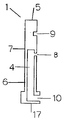
本発明の第1の形態である流体注入ピン(1)は、図1に例示されるように、その内部に設けられた流体通路となる長さ方向の中空空間(4)がその先端(5)側で封鎖された中空管(6)からなり、該中空管の管壁部を貫通して外周面(7)に開口する貫通孔(8)が設けられ、また、該中空管の外周面には、前記貫通孔の中心をとおる、中空管長さ方向の直線上に切り欠き凹部(9)が設けられた構造となっており、かかる流体注入ピンの中空空間の後端開口部(10)は流体供給源(11)に連通してなるとともに、該中空管が中空管の長さ方向に進退移動可能な移動手段(12)と接続される。
【0007】
本発明の流体注入ピンは、中空成形体を製造する場合に、これを雌雄一対からなる成形型のいずれか一方または両方の金型に設けて使用されるが、以下、図1に示される流体注入ピンを例にとって、その使用方法とともに、さらに詳細に説明する。
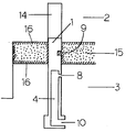
図2は、流体注入ピン(1)をその長さ方向が金型の成形面に対して垂直、すなわち成形型の開閉方向と同一方向になるように、雌雄(2,3)いずれか一方または両方の成形型(図2においては雄金型)に設けた場合の例であって、流体注入ピンは流体供給開始前の状態において、貫通孔(8)が雄金型(3)の金型成形面(13)より下方の金型内に、切り欠き凹部(9)が貫通孔より先端側でキャビティ内に位置するように取り付けられており、雌金型(2)の流体注入ピンの対応する位置には、型締時において該流体注入ピンの先端部を収納するための該流体注入ピンの先端部が嵌合し、摺動可能な金型凹部(14)が設けられている。
かかる凹部(14)の深さは流体注入ピンにおける切り欠き凹部や貫通孔(または中空外管貫通孔)のピン先端部からの位置や該ピンの移動距離によっても異なって特に限定されないが、前記したような流体注入ピンをその成形前後において移動させる場合に、該ピンの先端と相対する他の金型の金型面によってその移動が妨げられない程度の深さであればよい。
【0008】
流体注入ピン(1)を金型に設ける位置は、得られた中空成形体の使用目的によっては金型の最終製品相当部であってもよいが、場合によっては金型の非製品部に設け、成形終了後に該非製品部を切り離すことにより最終製品にピン跡を生ぜしめることもなく中空成形体を得ることができる。
流体注入ピン(1)をこのように金型に取り付けた後、たとえば両金型を開いて金型内に設けた樹脂通路を経由してキャビティ内に溶融樹脂(15)を供給し、所定のキャビティクリアランスになるまで金型を閉じる(型締)。溶融樹脂は流体注入ピンを包み込みながらキャビティ内を流動し、金型成形面(13)や流体注入ピンの切り欠き凹部(9)や外周面(7)と接触する部分は樹脂温度が低下、固化してスキン層(16)が形成される。このときの流体注入ピンの部分を拡大して図3に示す。
尚、溶融樹脂の供給にあたっては、所定のキャビティクリアランスになるまで型締した際に、少なくとも流体注入ピン(1)の周辺は完全に溶融樹脂で満たされるが、溶融樹脂がキャビティ内を完全に充填されてしまうことなく、目的とする中空成形体の中空部分に相当する程度の空隙が金型キャビティの溶融樹脂の流動末端部分で残存する程度にその供給量を調節することが好ましく、また、そのために溶融樹脂の供給ゲ−トの位置を調整することが好ましい。
金型を閉じた後、流体注入ピン(1)を、該ピンに設けた貫通孔(8)がピンの移動前の切り欠き凹部(9)の位置になるように移動手段(12)により雌金型(2)方向に突き出して移動させる。
流体注入ピンの移動により、切り欠き凹部(9)内に入り込んでいたスキン層は該凹部内に取り込まれたままその周辺のスキン層から削り取られ、当初の切り欠き凹部が接していた部分にはスキン層が欠落した未固化の溶融樹脂が現れる。流体注入ピンの移動を貫通孔が当初に切り欠き凹部が位置していたところで停止させると、貫通孔の開口部は上記のスキン層内部の溶融樹脂と直接接することとなる。このときの流体注入ピンの部分を拡大して図4に示す。
この状態において、貫通孔(8)から流体の注入を行えば、貫通孔の開口部にはスキン層は存在せず、溶融樹脂と直接接しているために、数kgf程度の低圧の流体であっても容易に溶融樹脂(15)中に供給することができ、流体の供給によって中空部を形成させながら溶融樹脂をキャビティ内に充満させ、この状態を維持しながら溶融樹脂を冷却固化することにより中空成形体が得られる。
【0009】
尚、流体注入ピン(1)の移動前後において切り欠き凹部(9)と貫通孔(8)の位置を一致させるためには、該ピンに設ける切り欠き凹部と貫通孔の位置が流体注入ピンの長さ方向において同一軸線上にあることが必要であり、この位置が同一軸線上にない場合には、流体注入ピンを長さ方向に移動させても、貫通孔の開口部が切り欠き凹部の存在していた位置と一致せず、貫通孔の開口部がスキン層で封鎖されて流体の注入が困難となって、流体注入ピン自体の回動操作も同時に要求されて操作が煩雑となる。
【0010】
このような流体注入ピン(1)の形状としては、通常はその外周の断面形状として円形ないしは楕円形である場合が多いが、四角形や六角形などであってもよく、その外観も断面形状に応じて円柱状、角柱状など任意である。
また、その内部の流体通路となる中空空間(4)は、該ピンの先端側で封鎖されていることが必要であるが、その形状自体は任意である。
貫通孔(8)や切り欠き凹部(9)を設ける位置は、成形過程におけるキャビティクリアランスなどによって適宜決定されるが、雌雄両金型間への溶融樹脂の供給開始時あるいは型締開始時において、切り欠き凹部がキャビティ内に位置し、流体注入ピンの先端(5)が他の金型に設けた金型凹部(14)内に挿入可能となるとともに、貫通孔が金型の成形面より下位の金型内にあってキャビティ内に開口しないように設けられる。
【0011】
かかる流体注入ピン(1)は通常金属製であり、その具体的な寸法は材質その他種々の条件で変わるが、少なくとも接続される移動手段によって該ピンが移動しえる程度の強度および流体の供給圧力に耐える強度を有することが必要であり、例えば流体注入ピンの外周断面および流体通路である中空空間が円形である場合には、その外周直径は3〜10mm程度であり、また、中空空間の断面直径は外周直径や管壁の厚さなどに応じて変わるが通常0.5〜8mm程度である。
また、貫通孔(8)は、通常、該ピンの長さ方向(軸方向)に対して直角に設けられるが、製品形状その他成形条件によっては上向きまたは下向きの角度をつけて設けられていてもよく、また、貫通孔は必ずしもその大きさがその全てで均一である必要もなく、中空空間側と外周面側とでその大きさが異なって適宜のテーパーが設けられていてもよい。
尚、貫通孔と切り欠き凹部の間隔は、流体供給開始時に流体注入ピンを対向する金型(図では雌金型)側に突き上げて移動させたときに、貫通孔が、移動前の切り欠きの位置と一致するような距離であればよい。
【0012】
また、切り欠き凹部(9)は該凹部を含むピン周りに形成した溶融樹脂のスキン層を流体注入ピン(1)を移動させることにより、該切り欠き凹部で削り取り、スキン層内部の溶融樹脂をむき出しにするためのものであるから、その目的を達する限りにおいてその形状は任意であって何ら制限されず、たとえば正面形状として円形、楕円形、三日月形、三角形、四角形等が、その深さ方向からみた断面形状としては四角形、V字形、U字形、半球形などが例示される。
かかる切り欠き凹部の正面形状の大きさは、流体注入ピンの移動によりスキン層が削り取られたのちのむき出しにされた溶融樹脂中に貫通孔より流体が供給できる程度の大きさであればよく、通常は貫通孔(8)の開口部と同程度かそれより少々大きい程度で十分であって、必要以上に大きくすることはその意味がないばかりか流体注入ピン自体もそれに伴って大きくなるため好ましくない。
また、その深さは、貫通孔の長さ、切り欠き凹部の形状や成形条件などによっても異なり、流体注入ピンの移動によりスキン層が削り取られて内部の溶融樹脂がむき出しにされる程度であれば特に制限されないが、浅すぎるとスキン層の削り取りが不十分となって溶融樹脂が露出せず、深すぎると溶融樹脂が伸長されてスキン層の削り取られた部分の外観を損ねるため、通常は0.2〜2mm程度である。
【0013】
貫通孔(8)の断面形状は円形、楕円形、三角形、四角形など任意であり、切り欠き凹部(9)の正面形状と同形ないしは類似の形状とされることが多い。
また、その大きさは供給する流体の供給圧力や供給量、溶融樹脂の物性などの条件によっても変わるが、一般にはその形状が円形である場合においてその直径が0.5〜2mm程度である。
【0014】
かかる流体注入ピンにおいて、その内部に設けられている流体通路となる中空空間(4)の後端開口部(10)は、従来より公知の流体供給ピンと同様に任意の構造により流体供給源(11)と接続され、通常、その任意の箇所において流体供給の開始、停止手段たとえばバルブが設けられていて、流体の供給開始や停止が任意に制御できるようになっている。また、流体注入ピンの後端部(17)は、該ピンの長さ方向に進退可能な移動手段(12)に接続され、該移動手段を作動させることによって流体注入ピンをキャビティ方向に押し出したり、金型内に引き込んだりすることができる。かかる移動手段そのものは従来より可動ピンを可動させる際に使用されているような公知の移動手段、たとえば油圧や空気圧を利用する方法が適用される。
【0015】
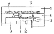
かかる流体注入ピン(1)の使用例としてピンをその長さ方向が成形時における成形型の開閉方向と同一方向になるように金型に設けた場合の例について述べたが、他の例として図5〜図7に示すように、雌雄(2,3)いずれか一方または両方の成形型(図においては雄金型)内に、流体注入ピンを格納するためのピン格納空間(18)を、連通孔(A)を介して雄金型の成形面(13)と連通するように設け、該格納空間内に、流体注入ピン(1)をその長さ方向が成形型の成形面(13)と平行、すなわち成形型の開閉方向に対して直角になるように、かつ該ピンの貫通孔(8)および切り欠き凹部(9)を設けた外周面が格納空間の上壁面と緊密に、摺動可能に接するとともに、貫通孔および切り欠き凹部が連通孔(A)の下端を通過可能に設けてなる金型を使用する方法が挙げられる。
もちろん、この場合においても先の場合と同様に、流体注入ピンの中空空間の後端開口部(10)は流体供給源(11)に連通してなるとともに、該ピンの後端部(17)が中空管の長さ方向に進退移動可能な移動手段(12)と接続されている。
【0016】
この方法による場合、少なくとも溶融樹脂の供給時から流体を供給するまでの間は、流体注入ピン(1)の切り欠き凹部(9)と連通孔(A)の位置が一致し、貫通孔(8)が連通孔(A)と重ならないようにすることが必要である。(図5)
また、金型面に設けた連通孔(A)の大きさは(深さ、断面形状、断面積など)特に制限なく任意であるが、流体注入ピン(1)に設けた切り欠き凹部(10)と同程度ないしはそれより大きいことが好ましい。
かかる連通孔(A)は、この目的のために別途設けてもよいが、最終製品のリブやボスの形成部分をこの目的に利用してもよい。
ピン格納空間(18)は、該空間内でピンがその長さ方向に移動可能な大きさであることが必要であり、また、流体注入ピン(1)の切り欠き凹部(8)や貫通孔(8)が設けられている外周面は少なくとも格納空間の上壁面と緊密に、摺動可能に接していることが必要であるが、場合によっては上下両面と緊密に、摺動可能に接していてもよい。
しかし、一般には図に示すように、格納空間の下面にピン支持台(19)を設け、該支持台上でピンを移動させながら流体注入ピン(1)の金型成形面側の外周面を格納空間の上壁面と緊密に摺動させることが多い。
この場合、格納空間の両側面が同時にピンの外周面に接していてもよいし、適宜の距離で離れていてもよい
また、流体注入ピン(1)をその長さ方向に移動させるための移動手段(12)は格納空間(18)内に設けてもよいし、適宜の連動手段を用いて金型外に設けてもよく、該ピンが移動可能であれば移動手段を設ける場所は任意である。
【0017】
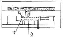
この方法による場合には、予め連通孔(A)と流体注入ピン(1)の切り欠き凹部(9)の位置が一致するように格納空間内の流体注入ピンを移動、配置した後、溶融樹脂を供給、型締し、スキン層(16)を金型成形面や溶融樹脂と接している流体注入ピンの切り欠き凹部に形成せしめ(図5)、その後切り欠き凹部内に形成されていたスキン層を削り取りながら、貫通孔(8)が移動前の切り欠き凹部の位置と一致するように流体注入ピンを移動させ(図6)、該貫通孔から流体を溶融樹脂中に注入すれば中空部を(22)を形成しつつ(図7)溶融樹脂がキャビティ内に充満されて中空成形体が得られ、流体注入ピンの移動方向が成形型の開閉方向と同一か直角方向かの相違はあっても、その機能は先に説明したと同じである。
【0018】
本発明の第2の態様である流体注入ピン(20)は、その内部に設けられた長さ方向の中空空間がその先端側で封鎖された肉厚筒状の中空管からなり、該中空管にはその管壁部を貫通して外周面に開口する貫通孔が、また、該中空管の外周面上であって、前記貫通孔を通りかつ中空管長さ方向の直線に対して垂直な断面上に切り欠き凹部がそれぞれ設けられ、かつ中空部の開口他端は流体供給源に連通してなるとともに、該中空管が中空管の円周方向に回動可能な回動手段(21)に接続されてなる流体注入ピンである。
【0019】
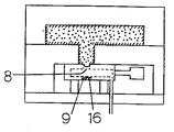
この流体注入ピン(20)は図8、図9に示すように、その内部に設けられた長さ方向の中空空間がその先端側で封鎖された中空管からなっており、該中空管にはその管壁部を貫通して外周面に開口する貫通孔(8)が設けられ、また該中空管の外周面上であって、前記貫通孔(8)を通りかつ中空管長さ方向の直線に対して垂直な断面上に切り欠き凹部(9)がそれぞれ設けられた構造となっており、その動きが円周方向での回動であること以外は先に述べた流体注入ピン(1)と機能は同じであり、切り欠き凹部や貫通孔の大きさ、形状なども同様であるが、流体注入ピンの外観を示す中空管それ自体は、その外周面が格納空間(18)の少なくとも上面と緊密に摺動しながら回動する必要があるため、通常は円柱状であり、これに対応して、格納空間上面の流体注入ピン(20)と摺動する部分は、該中空管の外周面に応じた曲面となっている。ここで、貫通孔と切り欠き凹部が、中空管長さ方向の直線に対して垂直な同一断面上に設けられていることは重要であって、これらが同一断面上にない場合には、その使用にあたって、流体注入ピンの回動と同時に該ピンの長さ方向への移動動作も同時に必要としてその操作が煩雑になる。また、同一断面上に設けられる貫通孔(8)と切り欠き凹部(9)の間隔は、切り欠き凹部を成形面の開放部に対応して配置したときに、貫通孔が同時に開放部と対応することがなければ任意であるが、一般には両者は90度ないしは180度の間隔をもって設けられる。
【0020】
このような流体注入ピン(20)を用いて中空成形体を製造する場合、雌雄いずれか一方または両方の成形型(図8、図9では雄型)の型内には流体注入ピン(30)を設置するための、先に述べたと同様のピン格納空間(18)が設けられ、該格納空間の連通孔(A)が開口している上面と流体注入ピンの外周面が緊密に回動可能に、かつ、流体注入ピンの貫通孔および切り欠き凹部が連通孔の位置に対応するように設けられてなる金型が使用される。
【0021】
かかる金型を使用して中空成形体を製造するには、雌雄両金型間に溶融樹脂を供給する前に、連通孔(A)の位置に切り欠き凹部(9)がくるように流体注入ピン(20)を回動させて配置した後、前記したように溶融樹脂の供給、型締を行い、その後連通孔(A)の位置に貫通孔(8)がくるように流体注入ピン(20)を回動させて、貫通孔より流体を溶融樹脂中に供給する。
この方法による場合には、溶融樹脂を供給し、型締すると、金型面および連通孔を介して接している流体注入ピンの切り欠き凹部を含む外周面で溶融樹脂が冷却、固化されてその表面にスキン層を形成する(図8)が、その後に連通孔(A)の位置に貫通孔(8)がくるように流体注入ピンを回動させることにより、切り欠き凹部面に形成されていたスキン層が流体注入ピンの回動に伴なって削り取られ、未固化の溶融樹脂と貫通孔が直接接することになり(図9)、貫通孔から溶融樹脂中に流体を容易に供給することができる。
【0022】
本発明の第3の態様である流体注入ピン(30)は、図10、図11に示すように、流体の供給をピン外周部から行うものであって、その先端より下位の外周面に切り込み凹部を有し、後端部がその長さ方向に移動可能な移動手段に接続されるとともに、後端部の外周面が流体供給源と接続された構造となっている。
【0023】
この流体注入ピン(30)は、ピン外周面(7)に切り欠き凹部(9)を設け、切り欠き凹部によってスキン層を削り取るという機能は先に述べた流体注入ピン(1、20)と同じであるが、ピンそれ自体に流体を供給するための機能は有しておらず、該ピンの外周面と該ピンを格納する格納装置(31)に設けたピン摺動壁との間の隙間を流体流路として利用するものである。
このため、流体注入ピン(30)は、該ピンとこれを格納する格納装置を組み合わせて使用される。
【0024】
ここで、流体注入ピン(30)の基本的形状は、太さが均一で、その断面形状が円形、四角形など任意の形状からなる棒状体であり、その先端部も場合によっては円錐状、角錐状のように先端部のみが細くなっていてもよいが、通常は平面形状である。
切り欠き凹部(9)の形状、大きさなどは前記したと同様であり、切り欠き凹部(9)を設ける位置もピン先端から下位であれば特に制限はないが、ピン先端からの距離が長くなれば、ピン自体の長さも長くなるため、僅かに下位である程度で十分であり、通常はピン先端から切り欠き凹部の先端までが0.5〜5mm程度である。
尚、この場合の切り欠き凹部(9)は一個所である必要はなく、同一円周上に複数個設けてもよく、場合によっては連続した溝状であってもよい。
【0025】
格納装置(31)は、流体注入ピン(30)を収納し、かつ該ピンをその長さ方向に摺動させるためのピン摺動孔(32)を有し、該摺動孔(31)は流体通路を介して流体供給源(11)と接続されており、流体注入ピン(30)をその長さ方向に移動させるための移動手段(12)はこの装置外であってもよいし、装置内に設けられていてもよい。(図では装置内に移動手段を設けた例を示している)
摺動孔(31)の長さ(深さ)は、流体注入ピンをその先端(5)が格納装置の外周面と同一になるようような長さであればよく、ことさらに長く深くする必要はない。
摺動孔(31)の形状は、流体注入ピン(30)の外周面が摺動孔側壁と摺動可能であればよいが、流体注入ピンの外周面と摺動孔側壁殿の隙間は流体通路としても利用するため、僅かに隙間が生じる程度が好ましい。
流体供給源(11)と連通する流体通路(33)は、この摺動孔の任意の位置で連通しておればよい。
【0026】
次に、図10、図11に基づいてかかる流体注入ピン(30)を用いて中空成形体を製造する例について述べる。
この例では、先に述べたと同様のピン格納空間(18)を雄金型(3)内に設け、ピン摺動孔(32)が金型成形面に設けた連通孔(A)の位置と一致し、かつ格納装置(31)の上端面と格納空間の上端面とが密接に接触するように格納装置を配置し、流体注入ピン(30)はその後端部に設けた移動手段(12)により、摺動孔(32)を介して連通孔(A)内に進退自由に移動できるようになっている。
この方法により中空成形体を製造する場合には、溶融樹脂の供給を開始する前に予め流体注入ピン(30)に設けた切り欠き凹部が連通孔(A)に位置するように該ピンを成形面側に突き出しておく。
このとき、切り欠き凹部の位置は、該凹部が完全に連通孔(A)内に入り込む程度でよく、連通孔(A)内の奥深くまで突き出す必要はない。
その後溶融樹脂の供給型締を行えば、先の例と同様に切り欠き凹部を含むピン外周面や金型面に接する表面部分で溶融樹脂が冷却固化され、スキン層が形成される。(図10)
その後、流体注入ピン(30)をその先端(5)がピン格納装置(31)の上端面と同じ位置になるまで降下させると、切り欠き凹部(9)内に形成されていたスキン層はその周辺のスキン層から削り取られて切り欠き凹部内に取り込まれ、ピン先端部分は未固化の溶融樹脂と直接接する状態となる。(図11)
この状態で、摺動孔(32)に連通する流体通路から流体を供給すると、流体は流体注入ピン(30)の外周面と摺動孔(32)の内周面との隙間から連通孔(A)内に入り込み、キャビティ内の溶融樹脂はこの流体によって中空部を形成しながらキャビティ内に充満される。
その後、溶融樹脂を冷却固化すれば、その内部に中空部を形成せしめた中空成形体が得られる。
【0027】
以上述べたような流体注入ピンを備えた金型を用いて成形することにより、スキン層などの固化層に遮られることなく、10kgf/cm2 以下程度の低圧の流体も溶融樹脂中に容易に注入することができる。
かかる目的で使用される流体は気体であっても液体であってもよく、従来より中空成形体を製造する場合に使用される流体であれば特に制限されることなく使用可能であるが、通常は空気、窒素、ヘリウム炭酸ガスなどの気体が使用される。
【0028】
尚、以上の説明においては、開放状態の金型間に溶融樹脂を供給する方法について述べたが、成形方法としては何らこのような方法に限定されず、前記したような流体注入ピンの機能を利用する限りにおいて、閉鎖された金型間に所定量の溶融樹脂を射出供給する射出成形法などにも同様に適用することができ、射出成形法による場合には、上記の説明における溶融樹脂供給後の型締を行う必要はない。
【0029】
また、成形型間に予め表皮材を供給後、上記と同様の方法を実施することにより、表皮材をその表面に貼合した中空成形体を製造することもできる。
かかる表皮材としては、目的とする中空成形体の表面加飾、クッション性の付与、断熱性の付与などの各目的に応じて適宜選択されるが、溶融樹脂の熱可塑性樹脂によって溶融あるいは破れなどが生じないことが必要である。
このような表皮材としては、例えば紙、織布、不織布、熱可塑性樹脂や熱可塑性エラストマーからなるシ−トもしくはフィルム、各種発泡シ−トなどの単独あるいはこれらの組み合わせからなる積層体が使用され、これら表皮材の表面にはシボ等の凹凸模様や印刷が施されていてもよい。
表皮材の厚みは材質によっても異なるが、通常0.5〜4mm程度である。
【0030】
また、かかる流体注入ピンを用いて熱可塑性樹脂製中空成形体を製造するにあたり、適用される樹脂としては従来より使用されている樹脂がそのまま適用されて何ら制限はなく、たとえばポリエチレンやポリプロピレンなどのポリオレフィン系樹脂、ポリスチレン、スチレン・アクリロニトリル共重合体、アクリロニトリル・スチレン・ブタジエン共重合体、ポリ塩化ビニル、ポリアミド、ポリカーボネート、ポリエチレンテレフタレート、ポリブチレンテレフタレート、ポリフェニレンエーテルなどの一般的な熱可塑性樹脂、熱可塑性エラストマー、これらの混合物あるいはこれらを用いたポリマーアロイなどが例示される。
これらの樹脂は必要に応じてタルク、ガラス繊維、ワラストナイトなどの充填材を含有していてもよく、もちろん、通常使用される酸化防止剤、紫外線防止剤などの各種の添加剤が含有されていてもよい。
【0031】
【発明の効果】
本発明の流体注入ピンおよびこのようなピンを備えた金型を使用することにより、複雑な装置や特殊な流体を用いることなく、たとえ流体供給前にスキン層が形成されていても、流体供給時には流体供給口を閉鎖させることなく、低圧の流体であっても容易に流体を溶融樹脂中に供給することができ、中空成形体を容易に製造することができる。
【0032】
【実施例】
以下、本発明を実施例で説明するが、本発明がこの実施例に限定されるものでないことは言うまでもない。
【0033】
実施例1
図5に示される金型(金型成形面の平面概略図を図12に示す。)を使用し、平板部厚さ3mm、リブ幅8mm、リブ高さ10mmで、リブ部に中空を有する図13に示される形状の中空成形体を製造した。
尚、図5には図示されていないが、この金型には図12に示されるように、キャビティ内の一端には射出機に接続された溶融樹脂供給口が設けられている。
先ず、金型の成形面下部の格納空間内に設けた流体注入ピンを移動させて、切り欠き凹部を連通孔の位置と一致させ、金型を閉じる。
次いで、溶融樹脂供給口から溶融状態のポリプロピレン樹脂(住友ノ−ブレンAX568、住友化学社製)をキャビティ内に供給する。このときの溶融樹脂の供給量はキャビティ容積の90%とした(図5)。
所定量の溶融樹脂の供給完了1秒後に流体注入ピンの貫通孔が連通孔の位置に一致するように流体供給ピンを移動させ(図6)、同時に貫通孔から8kgf/cm2 の圧縮空気の吐出を開始し、中空部を形成させながら溶融樹脂をキャビティ内に充満させた(図7)。
圧縮空気の圧力を保持したまま熱可塑性樹脂を50秒間冷却して、固化させた後、金型を開放し、図13に示す外観の中空成形体を得た。
得られた成形体のリブ部には長手方向に中空部が形成されており、圧縮気体の供給中も貫通孔の詰まりは全く生じなかった。
【0034】
実施例2
流体注入ピンが図8、図9に示されるような回動式である金型を使用する以外は実施例1と同様にして図13に示す外観の中空成形体を得た。
得られた中空成形体のリブ端は、流体注入ピンの外周形状に対応して若干R形状となっていたが、リブ部には長手方向に中空部が形成されており、圧縮気体の供給中も貫通孔の詰まりは全く生じなかった。
【0035】
実施例3
図10、図11に示されるような流体注入ピンの外周面と摺動孔の内周面との間隙を利用して流体を供給する流体供給ピンを備えた金型を使用する以外は実施例1と同様にして図13に示す外観の中空成形体を得ることができる。
【0036】
実施例4
図14に示されるような箱型形状であって、その中央部に2本の中空リブを有する形状の中空部成形体を製造するための金型形状を有し、キャビティ端部に流体注入ピンを設けた図2に示す金型を使用して、中空成形体を製造した。
尚、この金型における中央の2本のリブ部に対応する溝寸法は、幅8mm、深さ15mmであり、製品端部には取り付け穴を形成させるための貫通ピンがそれぞれの溝の両端側に合計4本設けられており、そのうちの一方の側の2本を流体注入ピンと兼ねた。
この流体注入ピンは図1に示すよう形状であって、直径8mmの肉厚円筒からなり、その表面には幅2mm、深さ1mmの三日月型の切り欠き凹部が設けられており、この凹部と同一軸線上であってそれより下位の位置に円筒内の中空空間(流体通路)と連通する直径1mmの流体注入用の断面が円形の貫通孔が設けられている。
両金型を開放し、貫通孔が金型成形面より下の金型内にあり、切り欠き凹部がキャビティ内に位置するように流体注入ピンを突き出す。
雌金型を降下させ、キャビティクリアランスが10mmになったところで降下を停止し、実施例1で用いたと同じ溶融状ポリプロピレン樹脂の供給を開始する。
溶融樹脂の供給完了と同時に雌金型の降下を再開して溶融樹脂をキャビティ内に流動させながら型締を行い、キャビティクリアランスが3mmになったところで型締を完了し、その後20Tの型締力を保持する。この時、流体注入ピンの周辺は溶融樹脂で充満されているが、キャビティ内には溶融樹脂は完全に充満されておらず、充填率は約90容量%である。
このときの流体注入ピンの周辺の様子を図3に示す。
型締完了直後に、貫通孔の位置が最初の切り欠き凹部の位置になるように流体注入ピンを上方に突き出し(このときの流体注入ピンの周辺の様子を図4に示す)、同時に貫通孔から8kgf/cm2 の圧縮空気の吐出を開始し、中空部を形成させながら溶融樹脂をキャビティ内に充満させた。
この状態を30秒間保持し、熱可塑性樹脂を冷却して、固化させた後、流体注入ピンを下方に引き下げて金型内に収納し、両金型を開放して図14に示す外観の中空成形体を得た。
得られた成形体は、流体注入ピンの貫通孔周辺とそれに繋がるリブ部の長手方向に中空部が形成されており、圧縮気体の供給中も貫通孔の詰まりは全く生じなかった。また、流体の供給を製品の取り付け部より行ったために、製品面にはピン穴もなく、外観も良好であった。
【図面の簡単な説明】
【図1】本発明の流体注入ピンのピン部分を断面概略図で示す。
【図2】本発明の流体注入ピンを設けた金型の断面該略図である。
【図3】図1で示す本発明の流体注入ピンの使用時における状態を示す概念図である。
【図4】図1で示す本発明の流体注入ピンの使用時における状態を示す概念図である。
【図5】本発明の流体注入ピンを備えた金型の使用時における状態を示す概念図である。
【図6】本発明の流体注入ピンを備えた金型の使用時における状態を示す概念図である。
【図7】本発明の流体注入ピンを備えた金型の使用時における状態を示す概念図である。
【図8】本発明の流体注入ピンを備えた金型の使用時における状態を示す概念図である。
【図9】本発明の流体注入ピンを備えた金型の使用時における状態を示す概念図である。
【図10】本発明の流体注入ピンを備えた金型の使用時における状態を示す概念図である。
【図11】本発明の流体注入ピンを備えた金型の使用時における状態を示す概念図である。
【図12】実施例1で使用した金型のキャビティ面の平面図である。
【図13】実施例1で得た成形体を示すものである。
【図14】実施例4で得た成形体の上面図およびその側面断面図である。
【符号の説明】
1:流体注入ピン
2:雌金型
3:雄金型
4:中空空間
5:流体注入ピン先端
6:中空管
7:流体注入ピン外周面
8:貫通孔
9:切り欠き凹部
10:中空空間後端開口部
11:流体供給源
12:移動手段
13:金型成形面
14:金型凹部
15:溶融樹脂
16:スキン層
17:注入ピン後端部
18:ピン格納空間
19:ピン支持台
20:流体注入ピン
21:回動手段
22:中空部
30:流体注入ピン
31:ピン格納装置
32:ピン摺動孔
33:流体通路
34:溶融樹脂供給口
35:貫通ピン
A:貫通孔[0001]
BACKGROUND OF THE INVENTION
The present invention relates to a fluid injection pin used for manufacturing a hollow molded body by supplying a fluid into a molten resin supplied between molds, and a hollow body molding die including the fluid injection pin.
[0002]
[Prior art]
Conventionally, a thermoplastic resin hollow molded body having a hollow portion inside a molded body has been used in many fields, and as a manufacturing method thereof, a fluid such as compressed air is supplied into a molten resin supplied between molds. The method is well known.
As a method for supplying the fluid, a method for injecting a fluid into a molten resin from a fluid supply port of a fluid supply pin provided in the cavity is known, and the injection pin is also fixed in the cavity. A method and a movable pin method for moving between a cavity and a mold are known.
[0003]
These known fluid supply pins have, for example, a hollow space that communicates with a fluid supply source inside the pin as a fluid passage, and a through hole that communicates the fluid passage with the tip portion or the outer peripheral surface of the pin has a tip portion of the pin. Or it has the structure opened to the outer peripheral surface, and the fluid is supplied in molten resin from the fluid supply port which is an opening part.
However, when such a fluid supply pin is used, the molten resin previously supplied between the molds is solidified at a low temperature portion such as the mold surface or the fluid supply pin, and a skin layer is formed on the contact surface. Therefore, the fluid supply port that opens on the surface of the fluid supply pin is covered with the skin layer, and the supply port becomes small, making it impossible to supply the fluid at a low pressure. In some cases, the supplied fluid is solidified. There was a problem that the fluid could not be pierced and the fluid could not be supplied into the molten resin.
[0004]
[Problems to be solved by the invention]
For this reason, the present inventors do not use a complicated device or a special fluid, and even if a skin layer is formed before supplying the fluid, the fluid supply port is not closed when the fluid is supplied. As a result of studying to develop a fluid supply pin that can easily supply the fluid into the molten resin even if it is a fluid of this type, the present invention has been achieved.
[0005]
[Means for Solving the Problems]
A first aspect of the present invention is a fluid injection pin for manufacturing a hollow molded body by supplying a fluid into a molten resin supplied between a pair of male and female molds, the hollow of which the tip is sealed. A through-hole formed in the tube and penetrating through the tube wall and opening to the outer peripheral surface, and the outer peripheral surface has a center of the through-hole. On the straight line in the length direction of the hollow tube A notch recess is provided, and the rear end opening of the hollow space communicates with the fluid supply source, and the hollow tube is connected to moving means that can move forward and backward in the length direction of the hollow tube. A second aspect of the present invention is a fluid injection pin for producing a hollow molded body by supplying a fluid into a molten resin supplied between a pair of male and female molding dies. A hollow tube sealed at the tip thereof, and a notch recess and a through-hole that penetrates the tube wall of the hollow tube and opens to the outer peripheral surface on the outer peripheral surface of the hollow tube. Provided on the same cross section perpendicular to the straight line in the length direction of the hollow tube, The rear end opening of the hollow tube communicates with a fluid supply source, and the hollow tube is connected to rotating means that can rotate in the circumferential direction of the hollow tube. A third aspect of the present invention is a fluid injection pin for producing a hollow molded body by supplying a fluid into a molten resin supplied between a pair of male and female molding dies, and its tip The lower outer peripheral surface has a notch, the rear end portion is connected to a moving means movable in the length direction, and the outer peripheral surface of the rear end portion is connected to a fluid supply source. Further, the present invention provides a hollow body molding die provided with such a fluid injection pin.
[0006]
DETAILED DESCRIPTION OF THE INVENTION
Hereinafter, the fluid supply pin of the present invention will be described.
As illustrated in FIG. 1, the fluid injection pin (1) according to the first embodiment of the present invention has a longitudinal hollow space (4) serving as a fluid passage provided therein and a tip (5). ) Side-closed hollow tube (6), provided with a through hole (8) that penetrates the tube wall of the hollow tube and opens to the outer peripheral surface (7). of On the outer peripheral surface, on the straight line in the length direction of the hollow tube passing through the center of the through hole The notch recess (9) is provided, and the rear end opening (10) of the hollow space of the fluid injection pin communicates with the fluid supply source (11). It is connected to a moving means (12) capable of moving back and forth in the length direction of the hollow tube.
[0007]
The fluid injection pin of the present invention is used in the case where a hollow molded body is manufactured by providing it on one or both molds of a pair of male and female. Taking the injection pin as an example, it will be described in more detail along with how to use it.
FIG. 2 shows that either the male or female (2, 3) or the fluid injection pin (1) has a length direction perpendicular to the molding surface of the mold, that is, the same direction as the opening / closing direction of the molding die. FIG. 2 is an example in which both molds (male mold in FIG. 2) are provided, and the fluid injection pin is a mold having a through hole (8) in the male mold (3) in a state before the fluid supply is started. A notch recess (9) is mounted in the mold below the molding surface (13) so as to be located in the cavity on the tip side from the through hole, and corresponds to the fluid injection pin of the female mold (2). At the position where the tip of the fluid injection pin is stored during mold clamping, the tip of the fluid injection pin is fitted and a slidable mold recess (14) is provided.
The depth of the concave portion (14) is not particularly limited and differs depending on the position of the notch concave portion and the through hole (or the hollow outer tube through hole) from the tip of the fluid injection pin and the moving distance of the pin. When such a fluid injection pin is moved before and after molding, the depth may be such that the movement is not hindered by the mold surface of another mold facing the tip of the pin.
[0008]
The position where the fluid injection pin (1) is provided in the mold may be a part corresponding to the final product of the mold depending on the purpose of use of the obtained hollow molded body, but in some cases, it is provided in a non-product part of the mold. By cutting off the non-product part after completion of the molding, a hollow molded body can be obtained without producing pin marks in the final product.
After the fluid injection pin (1) is attached to the mold in this way, for example, both molds are opened, and the molten resin (15) is supplied into the cavity via a resin passage provided in the mold, and a predetermined resin is supplied. Close the mold until the cavity clearance is reached (clamping). The molten resin flows through the cavity while wrapping the fluid injection pin, and the resin temperature decreases and solidifies at the mold forming surface (13) and the notch recess (9) and outer peripheral surface (7) of the fluid injection pin. Thus, the skin layer (16) is formed. The portion of the fluid injection pin at this time is enlarged and shown in FIG.
When supplying the molten resin, when the mold is clamped to a predetermined cavity clearance, at least the periphery of the fluid injection pin (1) is completely filled with the molten resin, but the molten resin completely fills the cavity. Therefore, it is preferable to adjust the supply amount so that a void corresponding to the hollow portion of the target hollow molded body remains in the flow end portion of the molten resin in the mold cavity. It is preferable to adjust the position of the molten resin supply gate.
After the mold is closed, the fluid injection pin (1) is moved by the moving means (12) so that the through hole (8) provided in the pin is positioned at the notch recess (9) before the pin is moved. It protrudes and moves in the direction of the mold (2).
Due to the movement of the fluid injection pin, the skin layer that has entered the notch recess (9) is scraped off from the surrounding skin layer while being taken into the recess, and the portion where the original notch recess is in contact is removed. An unsolidified molten resin with a missing skin layer appears. If the movement of the fluid injection pin is stopped when the through hole is initially cut out and the concave portion is located, the opening of the through hole comes into direct contact with the molten resin inside the skin layer. The portion of the fluid injection pin at this time is enlarged and shown in FIG.
In this state, if fluid is injected from the through-hole (8), the skin layer does not exist at the opening of the through-hole, and is in direct contact with the molten resin. However, the molten resin can be easily fed into the molten resin (15), and the molten resin is filled into the cavity while forming the hollow portion by supplying the fluid, and the molten resin is cooled and solidified while maintaining this state. A hollow molded body is obtained.
[0009]
In order to match the positions of the notch recess (9) and the through hole (8) before and after the movement of the fluid injection pin (1), the positions of the notch recess and the through hole provided on the pin are the positions of the fluid injection pin. If the position is not on the same axis in the length direction, even if the fluid injection pin is moved in the length direction, the opening of the through-hole is not cut away from the recess. It does not coincide with the existing position, the opening of the through hole is sealed with the skin layer, making it difficult to inject fluid, and the rotation operation of the fluid injection pin itself is required at the same time, which complicates the operation.
[0010]
The shape of such a fluid injection pin (1) is usually circular or elliptical as the cross-sectional shape of the outer periphery thereof, but may be a quadrangle or hexagon, and the external appearance is also a cross-sectional shape. Correspondingly, a columnar shape, a prismatic shape, etc. are arbitrary.
In addition, the hollow space (4) serving as the fluid passage inside of the pin needs to be sealed at the tip end side of the pin, but the shape itself is arbitrary.
The position where the through hole (8) and the notch recess (9) are provided is appropriately determined depending on the cavity clearance or the like in the molding process, but at the start of molten resin supply between the male and female molds or at the start of mold clamping, The notch recess is located in the cavity, and the tip (5) of the fluid injection pin can be inserted into the mold recess (14) provided in another mold, and the through hole is lower than the molding surface of the mold. It is provided so as not to open into the cavity.
[0011]
The fluid injection pin (1) is usually made of metal, and its specific dimensions vary depending on the material and other various conditions. However, the fluid injection pin (1) has sufficient strength and fluid supply pressure so that the pin can be moved by at least connected moving means. For example, when the hollow cross section of the fluid injection pin and the fluid passage have a circular shape, the outer diameter is about 3 to 10 mm, and the cross section of the hollow space The diameter varies depending on the outer diameter and the thickness of the tube wall, but is usually about 0.5 to 8 mm.
The through hole (8) is usually provided at a right angle to the length direction (axial direction) of the pin, but depending on the product shape and other molding conditions, it may be provided with an upward or downward angle. In addition, the through-holes are not necessarily required to be uniform in size, and may be provided with appropriate tapers with different sizes on the hollow space side and the outer peripheral surface side.
The interval between the through hole and the notch recess is such that when the fluid injection pin is pushed up and moved toward the opposing mold (female mold in the figure) at the start of fluid supply, the through hole is not cut before the movement. It is sufficient that the distance matches the position of.
[0012]
The notch recess (9) is formed by moving the fluid injection pin (1) to move the molten resin skin layer formed around the pin including the recess to remove the molten resin inside the skin layer. Since it is intended to be exposed, its shape is arbitrary and is not limited as long as its purpose is achieved. For example, a frontal shape such as a circle, an ellipse, a crescent, a triangle, a quadrangle, etc. can be used in the depth direction. Examples of the cross-sectional shape viewed from the side include a quadrangle, a V-shape, a U-shape, and a hemisphere.
The size of the front shape of the notch recess may be large enough to supply the fluid from the through hole into the exposed molten resin after the skin layer has been scraped off by the movement of the fluid injection pin. Usually, it is sufficient if it is about the same size as or slightly larger than the opening of the through-hole (8), and it is not meaningful to make it larger than necessary, and the fluid injection pin itself is also increased accordingly. Absent.
In addition, the depth varies depending on the length of the through hole, the shape of the notched recess, molding conditions, etc., and may be such that the skin layer is scraped off by the movement of the fluid injection pin and the molten resin inside is exposed. If it is too shallow, the skin layer will not be sufficiently shaved and the molten resin will not be exposed. It is about 0.2 to 2 mm.
[0013]
The cross-sectional shape of the through hole (8) is arbitrary, such as a circle, an ellipse, a triangle, and a quadrangle, and is often the same shape as or similar to the front shape of the notch recess (9).
Moreover, although the magnitude | size changes also with conditions, such as the supply pressure and supply amount of the fluid to supply, and the physical property of molten resin, generally when the shape is circular, the diameter is about 0.5-2 mm.
[0014]
In such a fluid injection pin, a hollow space (a fluid passage provided therein) 4 The rear end opening (10) is connected to the fluid supply source (11) by an arbitrary structure in the same manner as a conventionally known fluid supply pin, and usually starts or stops fluid supply at an arbitrary position, for example, a valve. Is provided so that the start and stop of fluid supply can be controlled arbitrarily. Further, the rear end portion (17) of the fluid injection pin is connected to a moving means (12) capable of moving back and forth in the length direction of the pin, and the fluid injection pin is pushed out toward the cavity by operating the movement means. Can be pulled into the mold. As the moving means itself, a known moving means such as conventionally used when moving the movable pin, for example, a method using hydraulic pressure or air pressure is applied.
[0015]
As an example of using the fluid injection pin (1), an example in which the pin is provided in the mold so that its length direction is the same as the opening / closing direction of the mold during molding has been described. As shown in FIGS. 5 to 7, a pin storage space (18) for storing the fluid injection pin is provided in one or both of the male and female (2, 3) molds (male mold in the figure). The fluid injection pin (1) is provided in the storage space so as to communicate with the molding surface (13) of the male mold through the communication hole (A). ), That is, perpendicular to the opening and closing direction of the mold, and the outer peripheral surface provided with the through hole (8) and the notch recess (9) of the pin is tightly connected to the upper wall surface of the storage space, The through-hole and the notch recess pass through the lower end of the communication hole (A). How to operably mold formed by providing the like.
Of course, in this case as well, as in the previous case, the rear end opening (10) of the hollow space of the fluid injection pin communicates with the fluid supply source (11) and the rear end (17) of the pin. Is connected to a moving means (12) capable of moving back and forth in the length direction of the hollow tube.
[0016]
In the case of this method, at least from the time of supplying the molten resin to the time of supplying the fluid, the position of the notch recess (9) of the fluid injection pin (1) and the communication hole (A) coincides, and the through hole (8 ) Does not overlap with the communication hole (A). (Fig. 5)
In addition, the size of the communication hole (A) provided in the mold surface (depth, cross-sectional shape, cross-sectional area, etc.) is not particularly limited and is not limited, but a notch recess (10 provided in the fluid injection pin (1)). It is preferable that it is the same as or larger than.
Such a communication hole (A) may be separately provided for this purpose, but a rib or boss forming part of the final product may be used for this purpose.
The pin storage space (18) needs to have a size such that the pin can move in the length direction in the space, and the notch recess (8) and the through hole of the fluid injection pin (1). It is necessary that the outer peripheral surface provided with (8) is in close contact with at least the upper wall surface of the storage space so as to be slidable, but in some cases, it is in close contact with both the upper and lower surfaces so as to be slidable. May be.
However, generally, as shown in the figure, a pin support base (19) is provided on the lower surface of the storage space, and the outer peripheral surface on the mold forming surface side of the fluid injection pin (1) is moved while moving the pin on the support base. It is often slid closely with the upper wall of the storage space.
In this case, both side surfaces of the storage space may be simultaneously in contact with the outer peripheral surface of the pin, or may be separated by an appropriate distance.
Further, the moving means (12) for moving the fluid injection pin (1) in the length direction thereof may be provided in the storage space (18), or provided outside the mold using appropriate interlocking means. If the pin is movable, the place where the moving means is provided is arbitrary.
[0017]
In the case of this method, after the fluid injection pin is moved and arranged in the storage space so that the position of the notch recess (9) of the communication hole (A) and the fluid injection pin (1) coincides, the molten resin And the mold is clamped, and the skin layer (16) is formed in the notch recess of the fluid injection pin in contact with the mold forming surface and the molten resin (FIG. 5), and then the skin formed in the notch recess While removing the layer, the fluid injection pin is moved so that the through hole (8) coincides with the position of the notch recess before the movement (FIG. 6), and the fluid is injected into the molten resin from the through hole. (22) (FIG. 7), the molten resin is filled into the cavity to obtain a hollow molded body, and there is a difference in whether the moving direction of the fluid injection pin is the same as or perpendicular to the opening and closing direction of the mold. However, the function is the same as described above.
[0018]
The fluid injection pin (20) according to the second aspect of the present invention comprises a thick cylindrical hollow tube in which a hollow space in the length direction provided therein is sealed off at the tip side thereof, The hollow pipe has a through-hole that penetrates through the tube wall and opens to the outer peripheral surface, and the outer peripheral surface of the hollow tube. On a cross section passing through the through hole and perpendicular to the straight line in the length direction of the hollow tube. Notch recesses are provided respectively, and the other open end of the hollow portion communicates with a fluid supply source, and the hollow tube is connected to a rotating means (21) capable of rotating in the circumferential direction of the hollow tube. It is a fluid injection pin connected.
[0019]
As shown in FIGS. 8 and 9, the fluid injection pin (20) is composed of a hollow tube in which a hollow space in the length direction provided in the fluid seal is sealed at the tip side, and the hollow tube Is provided with a through hole (8) penetrating the tube wall and opening to the outer peripheral surface, and the outer peripheral surface of the hollow tube On the cross section passing through the through hole (8) and perpendicular to the straight line in the length direction of the hollow tube It has a structure in which a notch recess (9) is provided, and the function is the same as that of the fluid injection pin (1) described above except that its movement is rotation in the circumferential direction. The size and shape of the notch recess and the through hole are the same, but the hollow tube itself showing the appearance of the fluid injection pin is such that its outer peripheral surface slides tightly against at least the upper surface of the storage space (18). Since it is necessary to rotate, it is usually cylindrical, and correspondingly, the portion sliding with the fluid injection pin (20) on the upper surface of the storage space has a curved surface corresponding to the outer peripheral surface of the hollow tube. It has become. Here, the through hole and the notch recess are On the same cross section perpendicular to the straight line in the length direction of the hollow tube It is important that they are cross section If not, the operation of the fluid injection pin is complicated because it requires a movement operation in the length direction of the fluid injection pin at the same time as the rotation of the fluid injection pin. Also the same cross section The interval between the through hole (8) and the notch recess (9) provided on the upper surface is such that when the notch recess is arranged corresponding to the open part of the molding surface, the through hole cannot simultaneously correspond to the open part. In general, the two are provided at intervals of 90 degrees or 180 degrees.
[0020]
When a hollow molded body is manufactured using such a fluid injection pin (20), the fluid injection pin (30) is placed in one or both of the male and female molds (male in FIGS. 8 and 9). A pin storage space (18) similar to that described above is provided, and the upper surface where the communication hole (A) of the storage space is open and the outer peripheral surface of the fluid injection pin can be tightly rotated. In addition, a mold is used in which the through hole and the notch recess of the fluid injection pin are provided so as to correspond to the position of the communication hole.
[0021]
In order to manufacture a hollow molded body using such a mold, before the molten resin is supplied between the male and female molds, fluid is injected so that the notch (9) is located at the position of the communication hole (A). After the pin (20) is rotated and arranged, the molten resin is supplied and the mold is clamped as described above, and then the fluid injection pin (20) so that the through hole (8) comes to the position of the communication hole (A). ) To feed the fluid into the molten resin from the through hole.
In this method, when the molten resin is supplied and the mold is clamped, the molten resin is cooled and solidified on the outer peripheral surface including the notch recess of the fluid injection pin that is in contact with the mold surface and the communication hole. A skin layer is formed on the surface (FIG. 8), and then the fluid injection pin is rotated so that the through hole (8) comes to the position of the communication hole (A). The skin layer is scraped off with the rotation of the fluid injection pin, so that the unsolidified molten resin and the through hole are in direct contact with each other (FIG. 9), and fluid can be easily supplied into the molten resin from the through hole. Can do.
[0022]
As shown in FIGS. 10 and 11, the fluid injection pin (30) according to the third aspect of the present invention supplies fluid from the outer peripheral portion of the pin, and cuts into the outer peripheral surface below the tip. The structure has a recess, the rear end is connected to a moving means movable in the length direction, and the outer peripheral surface of the rear end is connected to a fluid supply source.
[0023]
This fluid injection pin (30) is provided with a notch recess (9) in the pin outer peripheral surface (7), and the function of scraping the skin layer by the notch recess is the same as the fluid injection pin (1, 20) described above. However, there is no function for supplying fluid to the pin itself, and the gap between the outer peripheral surface of the pin and the pin sliding wall provided in the storage device (31) for storing the pin Is used as a fluid flow path.
For this reason, the fluid injection pin (30) is used in combination with the pin and a storage device for storing the pin.
[0024]
Here, the basic shape of the fluid injection pin (30) is a rod-shaped body having a uniform thickness and a cross-sectional shape of an arbitrary shape such as a circle or a quadrangle. However, only the tip portion may be thin as in the case of the shape, but it is usually a planar shape.
The shape and size of the notch recess (9) are the same as described above, and there is no particular limitation as long as the position of the notch recess (9) is also lower than the pin tip, but the distance from the pin tip is long. If this is the case, the length of the pin itself also becomes longer, so it is sufficient to be slightly lower, and usually the distance from the tip of the pin to the tip of the notch is about 0.5 to 5 mm.
In this case, the cutout recess (9) does not have to be provided at a single location, and a plurality of cutout recesses (9) may be provided on the same circumference.
[0025]
The storage device (31) houses a fluid injection pin (30) and has a pin sliding hole (32) for sliding the pin in its length direction. The sliding hole (31) The moving means (12) that is connected to the fluid supply source (11) via the fluid passage and moves the fluid injection pin (30) in the length direction thereof may be outside this device. It may be provided inside. (The figure shows an example in which a moving means is provided in the apparatus.)
The length (depth) of the sliding hole (31) may be any length so that the tip (5) of the fluid injection pin is the same as the outer peripheral surface of the storage device. There is no.
The shape of the sliding hole (31) may be any shape as long as the outer peripheral surface of the fluid injection pin (30) is slidable with the side wall of the sliding hole. Since it is also used as a passage, it is preferable that a slight gap is generated.
The fluid passage (33) communicating with the fluid supply source (11) may be communicated at any position of the sliding hole.
[0026]
Next, the example which manufactures a hollow molded object using this fluid injection | pouring pin (30) based on FIG. 10, FIG. 11 is described.
In this example, the same pin storage space (18) as described above is provided in the male mold (3), and the position of the communication hole (A) in which the pin sliding hole (32) is provided on the molding surface. The storage device is arranged so that the upper end surface of the storage device (31) and the upper end surface of the storage space are in intimate contact with each other, and the fluid injection pin (30) has moving means (12) provided at the rear end thereof. Thus, it is possible to move freely in the communication hole (A) through the sliding hole (32).
When a hollow molded body is manufactured by this method, the pin is molded so that a notch recess provided in the fluid injection pin (30) in advance is positioned in the communication hole (A) before the supply of the molten resin is started. Protruding to the surface side.
At this time, the position of the notch recess may be such that the recess completely enters the communication hole (A), and does not need to protrude deep into the communication hole (A).
Thereafter, when the molten resin supply mold is clamped, the molten resin is cooled and solidified at the outer peripheral surface of the pin including the notch recesses and the surface portion in contact with the mold surface, and a skin layer is formed. (Fig. 10)
Thereafter, when the fluid injection pin (30) is lowered until its tip (5) is at the same position as the upper end surface of the pin storage device (31), the skin layer formed in the notch recess (9) It is scraped off from the surrounding skin layer and taken into the notch recess, and the pin tip portion comes into direct contact with the unsolidified molten resin. (Fig. 11)
In this state, when a fluid is supplied from the fluid passage communicating with the sliding hole (32), the fluid communicates with the communication hole (from the clearance between the outer peripheral surface of the fluid injection pin (30) and the inner peripheral surface of the sliding hole (32) ( A) The molten resin in the cavity fills the cavity while forming a hollow portion by the fluid.
Thereafter, if the molten resin is cooled and solidified, a hollow molded body having a hollow portion formed therein can be obtained.
[0027]
10 kgf / cm without being blocked by a solidified layer such as a skin layer by molding using a mold having a fluid injection pin as described above. 2 The following low pressure fluid can be easily injected into the molten resin.
The fluid used for such a purpose may be a gas or a liquid, and can be used without any particular limitation as long as it is a fluid conventionally used for producing a hollow molded body. Gases such as air, nitrogen and helium carbon dioxide are used.
[0028]
In the above description, the method of supplying the molten resin between the molds in the open state has been described. However, the molding method is not limited to such a method, and the function of the fluid injection pin as described above is used. As long as it is used, the present invention can be similarly applied to an injection molding method in which a predetermined amount of molten resin is injected and supplied between the closed molds. There is no need to perform subsequent clamping.
[0029]
Moreover, after supplying a skin material between molds previously, the hollow molding which bonded the skin material on the surface can also be manufactured by implementing the same method as the above.
Such a skin material is appropriately selected according to each purpose such as surface decoration of the target hollow molded body, imparting cushioning properties, imparting heat insulating properties, etc., but is melted or broken by a thermoplastic resin of the molten resin It is necessary not to occur.
As such a skin material, for example, a sheet, a woven fabric, a nonwoven fabric, a sheet or film made of a thermoplastic resin or a thermoplastic elastomer, or a laminate made of various foamed sheets alone or a combination thereof is used. The surface of these skin materials may be provided with an uneven pattern such as embossing or printing.
The thickness of the skin material varies depending on the material, but is usually about 0.5 to 4 mm.
[0030]
Further, in manufacturing a hollow molded body made of thermoplastic resin using such a fluid injection pin, there is no limitation as a resin that has been used conventionally as it is applied, such as polyethylene and polypropylene General thermoplastic resins such as polyolefin resin, polystyrene, styrene / acrylonitrile copolymer, acrylonitrile / styrene / butadiene copolymer, polyvinyl chloride, polyamide, polycarbonate, polyethylene terephthalate, polybutylene terephthalate, polyphenylene ether, thermoplasticity Examples thereof include elastomers, mixtures thereof, and polymer alloys using these.
These resins may contain fillers such as talc, glass fiber, and wollastonite as needed, and of course, various additives such as antioxidants and UV inhibitors that are usually used. It may be.
[0031]
【The invention's effect】
By using the fluid injection pin of the present invention and a mold having such a pin, the fluid supply can be performed even if the skin layer is formed before the fluid supply without using a complicated device or a special fluid. Sometimes, even if it is a low-pressure fluid, without closing a fluid supply port, a fluid can be easily supplied in molten resin, and a hollow molded object can be manufactured easily.
[0032]
【Example】
EXAMPLES Hereinafter, although an Example demonstrates this invention, it cannot be overemphasized that this invention is not what is limited to this Example.
[0033]
Example 1
FIG. 12 is a view having a flat plate portion thickness of 3 mm, a rib width of 8 mm, a rib height of 10 mm, and a hollow portion in the rib portion using the mold shown in FIG. 5 (a schematic plan view of the mold forming surface is shown in FIG. 12) A hollow molded body having the shape shown in FIG. 13 was produced.
Although not shown in FIG. 5, the mold is provided with a molten resin supply port connected to an injection machine at one end in the cavity, as shown in FIG.
First, the fluid injection pin provided in the storage space below the molding surface of the mold is moved to make the notch recess coincide with the position of the communication hole, and the mold is closed.
Next, a molten polypropylene resin (Sumitomo No-Blen AX568, manufactured by Sumitomo Chemical Co., Ltd.) is supplied into the cavity from the molten resin supply port. The amount of molten resin supplied at this time was 90% of the cavity volume (FIG. 5).
One second after the supply of a predetermined amount of molten resin is completed, the fluid supply pin is moved so that the through hole of the fluid injection pin coincides with the position of the communication hole (FIG. 6), and at the same time, 8 kgf / cm @ 2 of compressed air is discharged from the through hole. Then, the cavity was filled with the molten resin while forming a hollow portion (FIG. 7).
The thermoplastic resin was cooled for 50 seconds while maintaining the pressure of the compressed air and solidified, and then the mold was opened to obtain a hollow molded body having the appearance shown in FIG.
A hollow portion was formed in the longitudinal direction in the rib portion of the obtained molded body, and no clogging of the through hole occurred at all during the supply of the compressed gas.
[0034]
Example 2
A hollow molded body having the appearance shown in FIG. 13 was obtained in the same manner as in Example 1 except that a die having a fluid injection pin as shown in FIGS. 8 and 9 was used.
The rib end of the obtained hollow molded body was slightly R-shaped corresponding to the outer peripheral shape of the fluid injection pin, but the rib portion is formed with a hollow portion in the longitudinal direction, and the compressed gas is being supplied. However, the clogging of the through holes did not occur at all.
[0035]
Example 3
Example other than using a mold having a fluid supply pin for supplying a fluid by utilizing a gap between the outer peripheral surface of the fluid injection pin and the inner peripheral surface of the sliding hole as shown in FIGS. The hollow molded body having the appearance shown in FIG.
[0036]
Example 4
14 has a mold shape for producing a hollow molded body having a shape of a box having two hollow ribs at the center, and a fluid injection pin at the end of the cavity. A hollow molded body was manufactured using the mold shown in FIG.
The groove dimensions corresponding to the central two ribs in this mold are 8 mm wide and 15 mm deep, and through pins for forming mounting holes are formed at both ends of each groove at the product end. A total of four are provided, and two on one side also serve as fluid injection pins.
The fluid injection pin has a shape as shown in FIG. 1 and is formed of a thick cylinder having a diameter of 8 mm. A crescent-shaped notch recess having a width of 2 mm and a depth of 1 mm is provided on the surface thereof. A through-hole having a circular cross section for fluid injection having a diameter of 1 mm, which communicates with the hollow space (fluid passage) in the cylinder, is provided on the same axis and at a lower position.
Both molds are opened, and the fluid injection pin protrudes so that the through hole is in the mold below the mold forming surface and the notch recess is located in the cavity.
The female mold is lowered, and when the cavity clearance reaches 10 mm, the descent is stopped, and supply of the same molten polypropylene resin as used in Example 1 is started.
Simultaneously with the completion of the supply of the molten resin, the lowering of the female mold is resumed and the mold is clamped while flowing the molten resin into the cavity. When the cavity clearance reaches 3 mm, the mold clamping is completed, and then the mold clamping force of 20T Hold. At this time, the periphery of the fluid injection pin is filled with molten resin, but the molten resin is not completely filled in the cavity, and the filling rate is about 90% by volume.
The state around the fluid injection pin at this time is shown in FIG.
Immediately after completion of mold clamping, the fluid injection pin protrudes upward so that the position of the through hole becomes the position of the first notch recess (the state of the periphery of the fluid injection pin is shown in FIG. 4), and at the same time, the through hole Then, discharge of compressed air of 8 kgf / cm @ 2 was started, and the cavity was filled with the molten resin while forming a hollow portion.
This state is maintained for 30 seconds, and the thermoplastic resin is cooled and solidified. Then, the fluid injection pin is pulled down and accommodated in the mold, and both molds are opened, and the hollow of the appearance shown in FIG. A molded body was obtained.
In the obtained molded body, hollow portions were formed around the through hole of the fluid injection pin and in the longitudinal direction of the rib portion connected thereto, and the clog of the through hole did not occur at all during the supply of compressed gas. In addition, since the fluid was supplied from the mounting portion of the product, there was no pin hole on the product surface and the appearance was good.
[Brief description of the drawings]
FIG. 1 is a schematic cross-sectional view of a pin portion of a fluid injection pin of the present invention.
FIG. 2 is a schematic cross-sectional view of a mold provided with a fluid injection pin of the present invention.
FIG. 3 is a conceptual diagram showing a state when the fluid injection pin of the present invention shown in FIG. 1 is used.
4 is a conceptual diagram showing a state when the fluid injection pin of the present invention shown in FIG. 1 is used. FIG.
FIG. 5 is a conceptual diagram showing a state in use of a mold having a fluid injection pin of the present invention.
FIG. 6 is a conceptual diagram showing a state in use of a mold having a fluid injection pin of the present invention.
FIG. 7 is a conceptual diagram showing a state in use of a mold having a fluid injection pin of the present invention.
FIG. 8 is a conceptual diagram showing a state in use of a mold having a fluid injection pin of the present invention.
FIG. 9 is a conceptual diagram showing a state in use of a mold having a fluid injection pin of the present invention.
FIG. 10 is a conceptual diagram showing a state in use of a mold having a fluid injection pin of the present invention.
FIG. 11 is a conceptual diagram showing a state in use of a mold having a fluid injection pin of the present invention.
12 is a plan view of a cavity surface of a mold used in Example 1. FIG.
FIG. 13 shows the molded body obtained in Example 1.
14 is a top view and a side cross-sectional view of a molded body obtained in Example 4. FIG.
[Explanation of symbols]
1: Fluid injection pin
2: Female mold
3: Male mold
4: Hollow space
5: Tip of fluid injection pin
6: Hollow tube
7: Fluid injection pin outer peripheral surface
8: Through hole
9: Notch recess
10: Hollow space rear end opening
11: Fluid supply source
12: Moving means
13: Molding surface
14: Mold recess
15: Molten resin
16: Skin layer
17: Rear end of injection pin
18: Pin storage space
19: Pin support
20: Fluid injection pin
21: Rotating means
22: Hollow part
30: Fluid injection pin
31: Pin storage device
32: Pin sliding hole
33: Fluid passage
34: Molten resin supply port
35: Through pin
A: Through hole
Claims (7)
Priority Applications (1)
| Application Number | Priority Date | Filing Date | Title |
|---|---|---|---|
| JP1634797A JP3707182B2 (en) | 1997-01-30 | 1997-01-30 | Fluid injection pin and hollow body molding die provided with the same |
Applications Claiming Priority (1)
| Application Number | Priority Date | Filing Date | Title |
|---|---|---|---|
| JP1634797A JP3707182B2 (en) | 1997-01-30 | 1997-01-30 | Fluid injection pin and hollow body molding die provided with the same |
Publications (2)
| Publication Number | Publication Date |
|---|---|
| JPH10211623A JPH10211623A (en) | 1998-08-11 |
| JP3707182B2 true JP3707182B2 (en) | 2005-10-19 |
Family
ID=11913852
Family Applications (1)
| Application Number | Title | Priority Date | Filing Date |
|---|---|---|---|
| JP1634797A Expired - Fee Related JP3707182B2 (en) | 1997-01-30 | 1997-01-30 | Fluid injection pin and hollow body molding die provided with the same |
Country Status (1)
| Country | Link |
|---|---|
| JP (1) | JP3707182B2 (en) |
Families Citing this family (2)
| Publication number | Priority date | Publication date | Assignee | Title |
|---|---|---|---|---|
| JP4529250B2 (en) * | 2000-07-27 | 2010-08-25 | 住友化学株式会社 | Method for producing fiber reinforced thermoplastic resin expansion molded body |
| KR101379382B1 (en) * | 2013-04-19 | 2014-04-01 | 구인모 | Water injector for injection molding |
-
1997
- 1997-01-30 JP JP1634797A patent/JP3707182B2/en not_active Expired - Fee Related
Also Published As
| Publication number | Publication date |
|---|---|
| JPH10211623A (en) | 1998-08-11 |
Similar Documents
| Publication | Publication Date | Title |
|---|---|---|
| US5665285A (en) | Method for producing a molded foam article with an integral skin | |
| JPH11268083A (en) | Method for injection molding accompanied with non-resin fluid | |
| JPH0516177A (en) | Method for injection molding of molded item of thermoplastic resin and metal mold for injection molding | |
| JP3707182B2 (en) | Fluid injection pin and hollow body molding die provided with the same | |
| JP3403016B2 (en) | Method for producing synthetic resin molded article having hollow part | |
| JPH09220731A (en) | Production of thermoplastic resin molded object having hollow part | |
| JP3994754B2 (en) | Composite mold manufacturing mold | |
| JPH06182862A (en) | Device for molding foamed body with skin | |
| JP3114028B2 (en) | Hollow injection molding method | |
| JP2777686B2 (en) | Molding method of skinned foam | |
| JP4689789B2 (en) | Molded resin magnet molding method | |
| JP3858453B2 (en) | Method for producing thermoplastic resin molded body having hollow portion | |
| JP3635838B2 (en) | Mold for manufacturing thermoplastic resin hollow moldings | |
| EP0884156B1 (en) | Process for producing thermoplastic resin hollow molded articles | |
| JPH0139328B2 (en) | ||
| JP3421395B2 (en) | Manufacturing method of hollow molded products | |
| JP3892518B2 (en) | Mold for molding using gas injection pin for gas injection molding | |
| JP3938433B2 (en) | Instrument panel manufacturing method | |
| JPH09309130A (en) | Molding die for injection molding | |
| JP2008006788A (en) | Surface-modification injection mold for thermoplastic resin | |
| JPH07124984A (en) | Preparation of injection-molded article and nozzle used for it | |
| KR100260139B1 (en) | Injection mold apparatus and injection thing method | |
| JPH0655563A (en) | Manufacture for hollow molded body | |
| JPH06297475A (en) | Manufacture of foam-molded article | |
| JP3974962B2 (en) | Insert molding equipment |
Legal Events
| Date | Code | Title | Description |
|---|---|---|---|
| A977 | Report on retrieval |
Free format text: JAPANESE INTERMEDIATE CODE: A971007 Effective date: 20050420 |
|
| A131 | Notification of reasons for refusal |
Free format text: JAPANESE INTERMEDIATE CODE: A131 Effective date: 20050426 |
|
| A521 | Written amendment |
Free format text: JAPANESE INTERMEDIATE CODE: A523 Effective date: 20050614 |
|
| TRDD | Decision of grant or rejection written | ||
| A01 | Written decision to grant a patent or to grant a registration (utility model) |
Free format text: JAPANESE INTERMEDIATE CODE: A01 Effective date: 20050712 |
|
| A61 | First payment of annual fees (during grant procedure) |
Free format text: JAPANESE INTERMEDIATE CODE: A61 Effective date: 20050725 |
|
| FPAY | Renewal fee payment (prs date is renewal date of database) |
Free format text: PAYMENT UNTIL: 20080812 Year of fee payment: 3 |
|
| RD05 | Notification of revocation of power of attorney |
Free format text: JAPANESE INTERMEDIATE CODE: R3D05 |
|
| FPAY | Renewal fee payment (prs date is renewal date of database) |
Free format text: PAYMENT UNTIL: 20090812 Year of fee payment: 4 |
|
| LAPS | Cancellation because of no payment of annual fees |