JP3704961B2 - Lifting storage device and lifting storage cabinet - Google Patents
Lifting storage device and lifting storage cabinet Download PDFInfo
- Publication number
- JP3704961B2 JP3704961B2 JP23681998A JP23681998A JP3704961B2 JP 3704961 B2 JP3704961 B2 JP 3704961B2 JP 23681998 A JP23681998 A JP 23681998A JP 23681998 A JP23681998 A JP 23681998A JP 3704961 B2 JP3704961 B2 JP 3704961B2
- Authority
- JP
- Japan
- Prior art keywords
- storage
- storage unit
- lowering
- lifting
- storage device
- Prior art date
- Legal status (The legal status is an assumption and is not a legal conclusion. Google has not performed a legal analysis and makes no representation as to the accuracy of the status listed.)
- Expired - Fee Related
Links
Images


Landscapes
- Combinations Of Kitchen Furniture (AREA)
Description
【0001】
【発明の属する技術分野】
本発明は、上下に配列した2つの収納部を必要に応じてその上下位置をそれぞれの昇降により入れ替えられる昇降収納装置に関するものである。
【0002】
【従来の技術】
吊り戸棚は元来、デッドスペースとなりがちな高所空間を有効に利用するのに利用されてきた。しかし、収納部が高所であるため踏み台等を用いないと物を自由に出し入れできない。近時では、吊り戸棚などの高所に設置される収納部を昇降できるように支持し、物の出し入れは下部位置で行い、収納は上部位置で行う昇降収納装置が提案され、実用されている。すなわち図9に示すように、収納部101を平行リンクに構成された支持アーム102に支持させ、収納キャビネット103に内装させたものである。図中104は厨房装置等の作業台である。参考文献としては特開平7−148029号公報、特開平7−148031号公報他があげられる。
【0003】
しかし、このような昇降収納装置では、昇降する高さ距離が小さいためキャビネット103をあまり高い位置に配置することができないという問題点があった。また、収納物により収納部101の重量が増したときに、上昇させるための操作に大きな力を加える必要があり、非力な女性や子供が使用するのに難があった。そして、このような昇降収納装置を図9のように厨房装置等の作業台上部に設置した場合では、収納部101はキャビネット103の手前側が下降位置となるので、収納部101を下降させた状態では流し台等の作業台104での作業ができなくなるという課題があった。
【0004】
そこで、本出願人は新たに図10、図11のような昇降収納装置を提案した。すなわち図の昇降収納装置は、互いに連携する連携手段を設けた2つの収納部を上下に配置することにより、上方の収納部を約180度の回動により降下させると、その勢いで下方の収納部を上昇させて上下位置を入れ換えることができるというものである。具体的には、上下に配列した第1の収納部111と第2の収納部112と、各収納部を支持支点113、114で回転自在に支持して各収納部を連結し、支持支点113、114の間に設定した回転支点115を中心として回転する支持部材116と、回転支点115をその軸線と直角な向きに水平方向に移動できるように支持する摺動支持部117と、第1の収納部111の背部にローラー118を設け、キャビネット119の背板119aにローラー118を当接させる構成としたものである。120は収納部112に設けられた把手である。
【0005】
この昇降収納装置は、使用者が把手120を握り、収納部112を前方に引き出すと、収納部112を支持し、収納部111と連結させている支持部材116が回転支点115を中心として回転するので、収納部112は上昇方向へ移動すると同時に収納部111を下降方向へと移動させる。収納部111の背部に設けられたローラー118は背板119aに当接し、移動時における収納部111の後方への突出を許さない構成としているので、支持部材116は回転支点115を摺動支持部117を介して前方へ移動させ、収納部111、112の干渉を最小限に抑えながら入れ替え動作を完了する。
【0006】
この本提案による昇降収納装置により、昇降する高さ距離を従来より大きく取ることが可能となり、より高い位置への設置が実現できると共に、各収納部の重量が増したときでも、一方の収納部の下降の勢いによりもう一方の収納部を上昇方向への力を軽減することができ、非力な女性や子供や高齢者にとっても使いやすい昇降収納装置を実現することが可能となった。加えて180度の回動により収納部の収納箱体より前方への突出分がなくなるので、収納部を下降させた状態での流し台等の作業台での作業が可能となるという効果があった。
【0007】
【発明が解決しようとする課題】
このような上下入れ換え式の昇降収納装置は、昇降上下移動により収納作業が飛躍的に軽減されるが、収納量や収納部への物品出し入れ性についての向上がさらに求められている。
【0008】
本発明は上下入れ換え収納機能を生かしながら、収納物品の収納効率や出し入れ性にも優れた昇降収納装置を提供するものである。
【0009】
【課題を解決するための手段】
上記課題を解決するため、本発明の昇降収納装置は、上下に配列した第1、第2の各収納部において、水平移動と回転移動により昇降動作する第1の収納部のラック体には固定棚を設け、鉛直方向に昇降動作する第2の収納部のラック体には前後方向に水平移動自在な可動棚を設けている。
【0010】
上記構成によって、水平移動成分を有する第1の収納部は可動棚ではなく固定棚で、収納作業において棚に水平力が加わらない仕様としているため、使い勝手に不具合は生じない。
【0011】
また第2の収納部は水平方向にスライド自在な可動棚を設けており、可動棚を出し入れさせることにより収納物品の収納作業性が大きく向上する。ここで、第2の収納部は昇降動作時における水平移動成分がないため可動棚の水平出し入れ操作に伴って収納部が動いてしまうことがなく使い勝手を阻害するというようなことがない。
【0012】
そして、各収納部に配した固定棚や可動棚により、上下立体的に物品を収納することができるので、収納量の向上や分別収納性が促進される。
【0013】
これにより、上下入れ換え収納機能の利便性を生かしながら、収納効率や作業性に優れた収納装置を実現することができる。
【0014】
【発明の実施の形態】
本発明の請求項1にかかる昇降収納装置は、上下配置位置に配列した第1、第2の各収納部と、前記第1、第2の各収納部を支持アームの両端部に回動自在に支持して第1の収納部と第2の収納部とを連結し、支持アームの中間部に設けた回転支点で回転することにより前記第1、第2の各収納部の上下位置を入れ換え可能に支持する収納部支持手段と、前記回転支点をその軸線と直角な向きに水平移動できるように支持する摺動支持部と、一方の収納部をほぼ鉛直方向に移動させる案内手段とを備えたものである。
【0015】
そして、第1の収納部を手前に引き出すと第1の収納部は支持支点が支持アームの回転支点を中心として前方に回動されるので、第2の収納部は支持支点が後方に回動しようとするが、第2の収納部は鉛直方向に移動させる案内手段により垂直方向へ案内をするので、支持アームが回動する動作でその回転支点を摺動支持部内で水平方向に押し出しながら、第2の収納部は第1の収納部の回動に伴って垂直方向に移動するため、第1の収納部と第2の収納部上下位置をスムーズに入れ換えることができる。
【0016】
本発明の請求項2にかかる昇降収納装置は、上下配置位置において、第1、第2の収納部の上下位置を入れ換えても、支持支点の軸がほぼ垂直位置に配列する構成であり、これにより収納部を上下入れ換えても収納部が収納箱体より前方への突出することがない。
【0017】
本発明の請求項3にかかる昇降収納装置は、案内手段を第2の収納部の背面近傍に設けたレール体に、第2の収納部の背部に設けたスライド体を係合して構成した案内手段を備えており、これにより第2の収納部の水平姿勢を保持する作用と、それを鉛直方向に案内する二つの作用をシンプルな構造で可能とすると共に、収納部の重心が前方に移動して支持支点を中心に収納部のラック体を回転させようとするモーメントをレール体がしっかりと支持するため、極めて強度の高い昇降収納装置を実現させることができる。
【0018】
本発明の請求項4にかかる昇降収納装置は、第1の収納部に固定棚を備え、第2の収納部に水平方向に移動自在な可動棚を備えており、上記構成から明らかなように各収納部に棚を設置し、収納物品を上下多段に高密度に立体収納させることにより、収納効率が向上する。また第2の収納部の棚を前後にスライド自在とすることにより、奥行の深い物品の収納や前後に配列させた物品の出し入れ性が向上する。
【0019】
また第2の収納部に物品を収納する際、スライド自在な可動棚を前後水平にスライドさせても、第2の収納部は鉛直方向にのみ昇降動作が規制されているため、これに伴って収納部が移動してしまうことがなく、収納作業に支障が生じることはない。
【0020】
一方、第1の収納部はスライド自在な可動棚を配せず固定棚としているので、水平移動と回転移動の合成運動による昇降動作をなす第1の収納部であっても棚が動くような心配がなく収納作業が行える。
【0021】
本発明の請求項5にかかる昇降収納キャビネットは、本発明の昇降装置を前面が開口したキャビネットの内部に配設することにより、キャビネット内の収納作業が上下立体的な収納が可能となり、収納目的に応じて適宜、棚の設置段数を設定すれば、収納量の向上や分別収納性が促進される。
【0022】
【実施例】
以下、本発明の実施例について図面を用いて説明する。
【0023】
(実施例1)
図1〜図7は本発明の実施例1を示す。
【0024】
まず実施例1が採用している昇降機構を、図1〜図5を用いて説明する。
【0025】
図1は本発明の実施例1における昇降機構の説明のための側方断面図である。図2は同実施例における昇降機構の正面要部断面図である。図3は同実施例における昇降機構のキャビネットを除いた状態における斜視図である。図4は一方の昇降機構を正面から見た要部断面図である。図5(a)〜(g)は同実施例における昇降機構の入れ替え動作順序を説明する側方断面図である。
【0026】
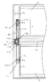
図1が示すように、昇降機構1は、第1の収納部2の支持支点P1と第2の収納部3の支持支点P2との間を連結する支持アーム4からなる収納部支持手段と、収納部2、3をその上下配置位置において収容し前面を開口したキャビネット5の両側板に取り付けられて前記支持アーム4の回転支点Oを水平方向に移動自在に支持する摺動支持部6と、第1の収納部2を回転角度にかかわらず一定の水平姿勢に維持する第1の収納部の姿勢規制手段7と、第2の収納部3の水平姿勢を維持しその昇降時の移動経路を鉛直方向に規制する案内手段8とを備えている。そして上記案内手段8を構成する断面がコの字型のガイドレール9aはキャビネット5の背面に取り付けられ、ガイドレール9aは第2の収納部3の背部の上下に設けられたガイドローラー9bを受け入れて前後の移動を阻止し、収納部3を垂直方向にだけ動くように案内する。
【0027】
以上の昇降機構1は図2に示すように、左右対称位置に昇降機構1L、1Rとして配備され、各支持アーム4L、4Rの各回転支点O間は連結軸10で連結され、左右の昇降機構1L、1Rが同期して動作するように構成されている。これにより第1、第2の各収納部2、3は左右が一体に支持され、収納物の片寄りにより荷重が左右でアンバランスな状態でも、ねじれたり傾くようなことがなく、左右の動きに差が生じるようなことが解消される。
【0028】
図4に示す昇降機構1Lを例にしてさらに説明すると、支持アーム4Lはその回転支点Oに対応する中間部で連結軸10で連結され水平移動軸11Lによりキャビネット12の側板内面に回動自在に支持され、水平移動軸11Lはその上下に配したローラ13a,13bを摺動支持部6Lの上下にコの字状の断面形状に形成された凹部に装入させ、摺動支持部6Lを水平方向に円滑に移動できるようにされている。また、水平移動軸11Lの先端には固定プーリ14Lが回転支点Oと同心で固定されている。
【0029】
支持アーム4Lの両端部の支持支点P1,P2位置に固定された軸15La、15Lbにはそれぞれ回転プーリ16Lと回転輪17Lが同心で回動自在に装着され、この回転プーリ16Lには第1の収納部2が、回転輪17Lには第2の収納部3が、それぞれ側板2L、3Lのほぼ中央部で固定支持されている。
【0030】
上記の固定プーリ14Lと回転プーリ16Lは同径寸法に設定され、両者間にはタイミングベルト18が掛け渡され、第1の収納部の姿勢規制手段7を構成している。
【0031】
ここで、昇降機構1による各収納部2、3の昇降動作について図5の(a)〜(g)に基づき説明する。
【0032】
図5の(a)に示すようにキャビネット5に収納された第1の収納部2と第2の収納部3との上下位置を入れ換えるときには、ガイドローラー9bを持たない第1の収納部2の操作ハンドルAを手前に引き出す。すると第1の収納部2は支持支点P1が支持アーム4の回転支点Oを中心として前方に回動されるので、第2の収納部3は支持支点P2が後方に回動しようとするが、第2の収納部3側はガイドレール9aが、ガイドローラー9bにかかる力を受け止め、ガイドローラー9b垂直方向へ案内をするので、支持アーム4が回動する動作でその回転支点Oを摺動支持部6内で水平方向に押し出しながら、図5(b)〜(d)に示すように第2の収納部3は第1の収納部2の回動に伴って垂直方向に上昇する。
【0033】
図5(d)に示す状態からさらに第1の収納部2を回動させると、前記と反対に支持アーム4の回動支点Oは元の位置に戻る方向に引き寄せられ、図5の(e)〜(f)に示すように、第1の収納部2は回動しつつキャビネット5内の下方に進入して行くのに連動して、第2の収納部3は垂直方向にさらに上昇し、図5の(g)に示すように第1の収納部2が第2の収納部3が元配列されていた下方位置に入ったとき、第2の収納部3は第1の収納部2が元配列されていた上方位置に上昇して、第1の収納部2と第2の収納部3との配列位置が上下入れ替わる。
【0034】
図5の(g)に示す状態から第1の収納部2を引き出し、上記操作と逆方向に回動させると、第2の収納部3は垂直方向に下降し、図5の(f)〜(a)の逆動作でそれぞれ元の配列位置に復帰させることができる。
【0035】
このような各収納部2、3の上下入れ替え動作において、第1の収納部2は支持アーム4によって支持支点P1に1軸で回動自在に支持されているので、支持支点P1に対する第1の収納部2の重心のずれや第1の収納部2の回動操作により水平姿勢が傾こうとする。ここで第1の収納部2に固定支持されている回転プーリ16は回転支点Oにある固定プーリ14との間でタイミングベルト18が掛け渡され、滑りのない形で回転連動している。今、回転プーリ16と固定プーリ14は同径に設定しており、タイミングベルト18は第1の収納部2が回動して支持アーム4の支持角度が変化する方向と逆の方向に同角度だけ第1の収納部2を回転させる働きを営み、結果として第1の収納部2は常にその水平姿勢を維持することができる。
【0036】
次に前記の昇降機構をベースに、収納部に収納用の棚を配した本発明の実施例1を図6、図7を用いて説明する。
【0037】
なお、図6(a)〜(g)は本実施例における入れ替え動作順序を説明する側方断面図である。図7は同実施例における昇降収納装置の正面要部断面図である。
【0038】
第1と第2の収納部2、3は前面を開口したラック体で構成され、第1の収納部2には棚19がそのラック体の両側面に取り付けられた棚受け24上に載置設置されている。
【0039】
第2の収納部3には水平前方に引き出し自在な可動棚20が設けられており、可動棚20はそのラック体の両側面に取り付けられたスライドレール21上に支持されて可動するようになっている。
【0040】
各収納部に配した棚19や可動棚20により、上下立体的な収納が可能となり、収納目的に応じて適宜、棚の設置段数を設定すれば、収納量の向上や分別収納性が促進される。
【0041】
ここで第2の収納部3の可動棚23を引き出し、収納物品22a、22bを出し入れしようとするとき、第2の収納部3の昇降動作は案内手段8により鉛直方向に規制され水平移動成分がないため、可動棚20の水平方向操作力に伴い、収納部3が動いてしまうことがない。
【0042】
可動棚20を引き出すことにより、奥行の深い収納物品22aの出し入れが容易になり、また小物品22bを前後に配列して出し入れする場合なども、前方の収納物品が邪魔にならない。
【0043】
また図6(g)の様に可動棚20が引き出された状態で、ここに重い収納物品23が積載されると、第2の収納部3の重心は支持支点P2よりかなり前方に移動し、収納部3のラック体を前方に回転移動させようとするモーメントが働くが、ガイドレール9aは収納部3のラック体の回転と移動を阻止すると共に、水平姿勢をしっかりと維持する。また、ガイドレール9aを剛性の高いものとし、これに係合するガイドローラー9bの上下間距離hを大きく取れば、極めて構造がシンプルで収納荷重に対する耐久強度の優れたものにすることができる。
【0044】
第1の収納部2の昇降動作は、水平運動と回転運動の合成された動作からなっているため、収納部2に水平力を与えたり、支持支点P1に対する重心が前方に大きくずれたりすると収納部2は移動し、図6(a)(g)の収納作業位置での停止ができなくなる。
【0045】
ここで第1の収納部2では棚受け上に載置するスタイルの棚19としているため、上記の様な使い勝手上の不具合を回避することができる。
【0046】
なお、本実施例では棚19は棚受け24により着脱自在で上下位置調整が可能な形態としているが、ビス等により収納部2のラック体に固着する構成としても、本願発明の目的を達成できるものである。
【0047】
(実施例2)
次に、本発明の実施例2の昇降収納装置を図8を用いて説明する。
【0048】
なお、図8(a)〜(g)は本発明の実施例2の昇降収納装置を示す側方断面図である。なお、実施例1と同一符号のものは同一構造を有し、説明は省略する。
【0049】
本実施例2において実施例1と異なる点は、第2の収納部3の水平姿勢保持と鉛直方向への案内手段8の構成である。ここでは水平姿勢保持手段として第1の収納部2と同様のタイミングベルト18を使った方式をとっており、鉛直方向へ移動を規制する手段としてリンク25を使用している。リンク25は一方端25aをキャビネットの側面12に回転自在に連結し、また他方端25bを支持アーム4上に回転自在に連結し、第2の収納部3の移動経路をほぼ鉛直方向に規制している。
【0050】
図8の(a)から(d)に向けて第1の収納部2を前方に引き出し、支持アーム4を回転させていくと、リンク25の突っ張り作用で回転支点Oは前方に移動し、(d)から(g)に向けてはリンク25の引っ張り作用により回転支点Oは後方に移動し、このとき支持支点P2はほぼ鉛直方向に近い軌跡で案内される。
【0051】
第1の収納部2の固定棚19と第2の収納部3の可動棚20は実施例1と同じで、同様に収納作業性に優れた昇降収納装置を実現することができる。
【0052】
【発明の効果】
以上説明したように本発明の請求項1記載の昇降収納装置は、収納物品を上下多段に高密度に立体収納させることにより、収納効率を向上させることができ、空間の有効活用が促進される。また棚を前後にスライド自在とすることにより、奥行の深い物品の収納や前後に配列させた物品の出し入れ性が向上する。また、この可動棚を、昇降動作の際に水平移動成分を持たない第2の収納部側に設けることにより、可動棚の前後スライド動作に伴って収納部そのものが移動してしまうことがなく、収納作業に支障が生じることはない。
【0053】
一方、第1の収納部はスライド自在な可動棚を配せず固定棚としているので、水平移動と回転移動の合成運動による昇降動作をなす第1の収納部であっても棚が動くような心配がなく収納作業が行える。
【0054】
また、請求項2記載の昇降装置は、収納部の上下位置を入れ換えても、支持支点の軸がほぼ垂直位置に配列する構成であり、これにより収納部を上下入れ換えても収納部が収納箱体より前方への突出することがない。
【0055】
また、請求項3記載の昇降収納装置は、第2の収納部の水平姿勢を保持する作用と、それを鉛直方向に案内する二つの作用がシンプルな構造で可能となると共に、第2の収納部に設けられた可動棚を引き出した時、収納部の重心が前方に移動して支持支点を中心に収納部を回転させようとするモーメントをレール体がしっかりと支持するため、極めて強度の高い昇降収納装置を実現させることができる。
【0056】
このように、本発明によれば、各収納部の昇降動作特性に最適な収納形態を構成し、極めて使い勝手が良く収納効率の高い昇降収納装置が実現可能となる。
【図面の簡単な説明】
【図1】 本発明の実施例1における昇降収納装置の側方断面図
【図2】 図1の昇降収納装置の正面要部断面図
【図3】 図1の昇降収納装置の斜視図
【図4】 図2の一方の昇降機構を正面から見た要部断面図
【図5】 (a)〜(g)は本発明の実施例1における昇降収納装置の入れ替え動作順序を説明する側方断面図
【図6】 (a)〜(g)は本発明の実施例1における昇降収納装置の入れ替え動作順序を説明する側方断面図
【図7】 同実施例1における昇降収納装置の正面要部断面図
【図8】 本発明の実施例2における昇降収納装置の入れ替え動作順序を説明する側方断面図
【図9】 従来の昇降収納装置を示す側方断面図
【図10】 本出願人の提案する昇降収納装置を示す側方断面図
【図11】 (a)〜(g)は同昇降収納装置の入れ替え動作順序を説明する側方断面図
【符号の説明】
1 昇降機構
2 第1の収納部
3 第2の収納部
4 支持アーム(収納部支持手段)
5 キャビネット
6 摺動支持部
7 姿勢規制手段
8 案内手段
19 固定棚
20 可動棚
9a レール体
9b スライド体
O 回転支点
P1 第1の収納部の支持支点
P2 第2の収納部の支持支点[0001]
BACKGROUND OF THE INVENTION
The present invention relates to a lifting and lowering storage device in which two storage units arranged in the vertical direction can be switched by moving up and down as needed.
[0002]
[Prior art]
The hanging cupboard has been originally used to effectively use the high space that tends to be a dead space. However, since the storage section is high, objects cannot be taken in and out without using a step or the like. Recently, a storage unit installed in a high place such as a hanging cupboard is supported so that it can be moved up and down, and an elevating storage device is proposed and put into practical use in which the storage and removal of objects is performed at the lower position and storage is performed at the upper position. . That is, as shown in FIG. 9, the
[0003]
However, such a lifting and lowering storage device has a problem that the
[0004]
Therefore, the present applicant has newly proposed a lifting and lowering storage device as shown in FIGS. That is, the lifting and lowering storage device shown in the drawing arranges two storage portions provided with cooperation means that cooperate with each other, so that when the upper storage portion is lowered by about 180 degrees of rotation, the lower storage device is moved with that force. It is possible to change the vertical position by raising the part. Specifically, the
[0005]
In this lifting and lowering storage device, when the user holds the
[0006]
This proposed lifting and lowering storage device makes it possible to increase the height of the lifting and lowering as compared with the prior art, and it can be installed at a higher position, and even when the weight of each storage portion increases, one storage portion As a result of the downward movement, the force in the upward direction of the other storage portion can be reduced, and an elevating storage device that is easy to use for less powerful women, children, and the elderly can be realized. In addition, since the portion of the storage portion protruding forward from the storage box body is eliminated by the rotation of 180 degrees, there is an effect that it is possible to work on a work table such as a sink in a state where the storage portion is lowered. .
[0007]
[Problems to be solved by the invention]
In such an up-and-down changing type lifting and lowering storage device, the storage work is remarkably reduced by the up-and-down movement, but further improvement in the storage amount and the ability to put in and out the article in the storage portion is further required.
[0008]
The present invention provides an elevating and lowering storage device that is excellent in storage efficiency and putting in and out of stored articles while making use of the up-and-down switching storage function.
[0009]
[Means for Solving the Problems]
In order to solve the above problems, the lifting and lowering storage device of the present invention is fixed to the rack body of the first storage portion that moves up and down by horizontal movement and rotational movement in the first and second storage portions arranged vertically. A shelf is provided, and a movable shelf that is horizontally movable in the front-rear direction is provided in the rack body of the second storage unit that moves up and down in the vertical direction.
[0010]
With the above configuration, the first storage unit having a horizontal movement component is not a movable shelf, but a fixed shelf, and is configured so that a horizontal force is not applied to the shelf during the storage operation.
[0011]
The second storage section is provided with a movable shelf that can slide in the horizontal direction, and the storage workability of the stored articles is greatly improved by moving the movable shelf in and out. Here, since the second storage unit has no horizontal movement component during the lifting / lowering operation, the storage unit does not move in accordance with the horizontal loading / unloading operation of the movable shelf, and the usability is not hindered.
[0012]
Since articles can be stored in three dimensions up and down by the fixed shelves and movable shelves arranged in the respective storage units, the storage capacity is improved and the separability is facilitated.
[0013]
Accordingly, it is possible to realize a storage device that is excellent in storage efficiency and workability while taking advantage of the convenience of the up / down switching storage function.
[0014]
DETAILED DESCRIPTION OF THE INVENTION
According to a first aspect of the present invention, there is provided a lifting and lowering storage device, wherein each of the first and second storage portions arranged in the vertical arrangement position and the first and second storage portions can be rotated to both ends of the support arm. a first housing portion supporting a second housing portion coupled to, replaced the vertical position of the first, second respective housing portion by rotating at a rotation fulcrum provided on the middle portion of the support arm a housing portion supporting means to movably supported, a sliding support portion supporting the rotating fulcrum on the axis perpendicular direction so as to be horizontally moved, and guide means for moving the one housing part substantially in the vertical direction It is equipped with.
[0015]
When the first storage portion is pulled out, the support fulcrum of the first storage portion is rotated forward about the rotation fulcrum of the support arm, so that the support fulcrum of the second storage portion is rotated backward. However, since the second storage portion guides in the vertical direction by the guide means that moves in the vertical direction, the support arm rotates while pushing the rotation fulcrum horizontally in the sliding support portion, Since the second storage unit moves in the vertical direction as the first storage unit rotates, the vertical positions of the first storage unit and the second storage unit can be switched smoothly.
[0016]
The lifting and lowering storage device according to
[0017]
The lifting and lowering storage device according to
[0018]
The lifting and lowering storage apparatus according to
[0019]
In addition, when storing the article in the second storage unit, even if the movable movable shelf is slid back and forth horizontally, the second storage unit is restricted to move up and down only in the vertical direction. There is no movement of the storage section, and no trouble occurs in the storage work.
[0020]
On the other hand, since the first storage unit is not a slidable movable shelf and is a fixed shelf, the shelf moves even in the first storage unit that moves up and down by the combined movement of horizontal movement and rotational movement. It can be stored without worry.
[0021]
The lifting / lowering cabinet according to
[0022]
【Example】
Embodiments of the present invention will be described below with reference to the drawings.
[0023]
Example 1
1 to 7
[0024]
First, the elevating mechanism employed in the first embodiment will be described with reference to FIGS.
[0025]
FIG. 1 is a side sectional view for explaining an elevating mechanism in
[0026]
As shown in FIG. 1, the elevating
[0027]
As shown in FIG. 2, the elevating
[0028]
The
[0029]
A rotating
[0030]
The fixed
[0031]
Here, the raising / lowering operation | movement of each
[0032]
As shown in FIG. 5A, when the upper and lower positions of the
[0033]
When the
[0034]
When the
[0035]
In such an up-and-down switching operation of the
[0036]
Next, a first embodiment of the present invention in which a storage shelf is arranged in the storage portion based on the lifting mechanism will be described with reference to FIGS.
[0037]
FIGS. 6A to 6G are side sectional views for explaining the order of replacement operation in the present embodiment. FIG. 7 is a front cross-sectional view of the main part of the lifting and lowering storage device in the same embodiment.
[0038]
The first and
[0039]
The
[0040]
The
[0041]
Here, when the
[0042]
By pulling out the
[0043]
When the
[0044]
The raising / lowering operation of the
[0045]
Here, in the
[0046]
In this embodiment, the
[0047]
(Example 2)
Next, a lifting and lowering storage apparatus according to
[0048]
FIGS. 8A to 8G are side sectional views showing the lifting and lowering storage device according to the second embodiment of the present invention. In addition, the thing of the same code | symbol as Example 1 has the same structure, and abbreviate | omits description.
[0049]
The second embodiment differs from the first embodiment in the configuration of the horizontal posture holding of the
[0050]
When the
[0051]
The fixed
[0052]
【The invention's effect】
As described above, the lifting and lowering storage device according to
[0053]
On the other hand, since the first storage unit is not a slidable movable shelf and is a fixed shelf, the shelf moves even in the first storage unit that moves up and down by the combined movement of horizontal movement and rotational movement. It can be stored without worry.
[0054]
Further, the lifting device according to
[0055]
In addition, the lifting and lowering storage device according to
[0056]
As described above, according to the present invention, it is possible to realize a storage form that is optimal for the lifting operation characteristics of each storage unit and that is extremely convenient and has high storage efficiency.
[Brief description of the drawings]
1 is a side cross-sectional view of a lifting / lowering storage device according to a first embodiment of the present invention. FIG. 2 is a front sectional view of a main part of the lifting / lowering storage device of FIG. 1. FIG. 4 is a cross-sectional view of a main part when one lifting mechanism in FIG. 2 is viewed from the front. FIGS. 5 (a) to 5 (g) are side cross-sections for explaining the replacement operation sequence of the lifting / lowering storage device in
DESCRIPTION OF
DESCRIPTION OF
Claims (5)
Priority Applications (1)
| Application Number | Priority Date | Filing Date | Title |
|---|---|---|---|
| JP23681998A JP3704961B2 (en) | 1998-08-24 | 1998-08-24 | Lifting storage device and lifting storage cabinet |
Applications Claiming Priority (1)
| Application Number | Priority Date | Filing Date | Title |
|---|---|---|---|
| JP23681998A JP3704961B2 (en) | 1998-08-24 | 1998-08-24 | Lifting storage device and lifting storage cabinet |
Publications (3)
| Publication Number | Publication Date |
|---|---|
| JP2000060661A JP2000060661A (en) | 2000-02-29 |
| JP2000060661A5 JP2000060661A5 (en) | 2004-09-16 |
| JP3704961B2 true JP3704961B2 (en) | 2005-10-12 |
Family
ID=17006262
Family Applications (1)
| Application Number | Title | Priority Date | Filing Date |
|---|---|---|---|
| JP23681998A Expired - Fee Related JP3704961B2 (en) | 1998-08-24 | 1998-08-24 | Lifting storage device and lifting storage cabinet |
Country Status (1)
| Country | Link |
|---|---|
| JP (1) | JP3704961B2 (en) |
Families Citing this family (4)
| Publication number | Priority date | Publication date | Assignee | Title |
|---|---|---|---|---|
| JP4655417B2 (en) * | 2001-06-14 | 2011-03-23 | パナソニック株式会社 | Lifting storage device |
| WO2020003350A1 (en) * | 2018-06-25 | 2020-01-02 | 三菱電機株式会社 | Control panel of elevator |
| CN112890440B (en) * | 2021-03-09 | 2022-09-16 | 江西阳光安全设备集团有限公司 | Book bookshelf is got to library eminence |
| CN113827045B (en) * | 2021-09-25 | 2023-04-28 | 杨永鹏 | Hospital information record strorage device of convenient searching |
-
1998
- 1998-08-24 JP JP23681998A patent/JP3704961B2/en not_active Expired - Fee Related
Also Published As
| Publication number | Publication date |
|---|---|
| JP2000060661A (en) | 2000-02-29 |
Similar Documents
| Publication | Publication Date | Title |
|---|---|---|
| JP3704961B2 (en) | Lifting storage device and lifting storage cabinet | |
| JPH06245829A (en) | Up and down device for a drawer of storage box | |
| JP2946281B2 (en) | Stacker crane | |
| JP2000060661A5 (en) | ||
| CN216166298U (en) | Drawer for control cabinet with good bearing capacity | |
| JP3704964B2 (en) | Lifting storage device and lifting storage cabinet | |
| JP3704962B2 (en) | Lifting storage device and lifting storage cabinet | |
| JP2000060662A5 (en) | ||
| JP3699577B2 (en) | Lifting storage device | |
| CN219433566U (en) | Refrigerator with a refrigerator body | |
| JP2000060664A5 (en) | ||
| JP6216020B1 (en) | Article moving device | |
| JP3699558B2 (en) | Storage part elevating method and elevating / retracting apparatus using the same | |
| JP3785761B2 (en) | Kitchen storage device | |
| JP3704963B2 (en) | Lifting storage device and lifting storage cabinet | |
| JP2001087048A (en) | Inclinable movable rack | |
| JP3699578B2 (en) | Lifting storage device | |
| CN219160749U (en) | Shelf device and storage equipment | |
| CN219771163U (en) | Automatic blanking machine for glass | |
| CN112190041B (en) | Sliding rail | |
| CN216220877U (en) | Solid wood sofa capable of storing books | |
| JP2001029147A (en) | Furniture unit for high spot and shelf elevating device | |
| JP2861551B2 (en) | Rotary shelf equipment | |
| JP5322814B2 (en) | Grill unit and heating cooker | |
| JPH10273205A (en) | Article storing equipment |
Legal Events
| Date | Code | Title | Description |
|---|---|---|---|
| A977 | Report on retrieval |
Free format text: JAPANESE INTERMEDIATE CODE: A971007 Effective date: 20040506 |
|
| A131 | Notification of reasons for refusal |
Free format text: JAPANESE INTERMEDIATE CODE: A131 Effective date: 20050215 |
|
| A521 | Written amendment |
Free format text: JAPANESE INTERMEDIATE CODE: A523 Effective date: 20050318 |
|
| RD01 | Notification of change of attorney |
Free format text: JAPANESE INTERMEDIATE CODE: A7421 Effective date: 20050629 |
|
| TRDD | Decision of grant or rejection written | ||
| A01 | Written decision to grant a patent or to grant a registration (utility model) |
Free format text: JAPANESE INTERMEDIATE CODE: A01 Effective date: 20050705 |
|
| A61 | First payment of annual fees (during grant procedure) |
Free format text: JAPANESE INTERMEDIATE CODE: A61 Effective date: 20050718 |
|
| S111 | Request for change of ownership or part of ownership |
Free format text: JAPANESE INTERMEDIATE CODE: R313113 |
|
| R350 | Written notification of registration of transfer |
Free format text: JAPANESE INTERMEDIATE CODE: R350 |
|
| FPAY | Renewal fee payment (event date is renewal date of database) |
Free format text: PAYMENT UNTIL: 20090805 Year of fee payment: 4 |
|
| S533 | Written request for registration of change of name |
Free format text: JAPANESE INTERMEDIATE CODE: R313533 |
|
| FPAY | Renewal fee payment (event date is renewal date of database) |
Free format text: PAYMENT UNTIL: 20090805 Year of fee payment: 4 |
|
| R350 | Written notification of registration of transfer |
Free format text: JAPANESE INTERMEDIATE CODE: R350 |
|
| LAPS | Cancellation because of no payment of annual fees |