JP3703936B2 - Soil boring device and soil boring method - Google Patents
Soil boring device and soil boring method Download PDFInfo
- Publication number
- JP3703936B2 JP3703936B2 JP07268497A JP7268497A JP3703936B2 JP 3703936 B2 JP3703936 B2 JP 3703936B2 JP 07268497 A JP07268497 A JP 07268497A JP 7268497 A JP7268497 A JP 7268497A JP 3703936 B2 JP3703936 B2 JP 3703936B2
- Authority
- JP
- Japan
- Prior art keywords
- rod
- push
- pull unit
- soil
- soil boring
- Prior art date
- Legal status (The legal status is an assumption and is not a legal conclusion. Google has not performed a legal analysis and makes no representation as to the accuracy of the status listed.)
- Expired - Lifetime
Links
- 239000002689 soil Substances 0.000 title claims description 52
- 238000000034 method Methods 0.000 title claims description 10
- 238000010168 coupling process Methods 0.000 claims description 24
- 230000008878 coupling Effects 0.000 claims description 23
- 238000005859 coupling reaction Methods 0.000 claims description 23
- 241000309551 Arthraxon hispidus Species 0.000 claims description 16
- 238000007373 indentation Methods 0.000 claims description 15
- 210000000078 claw Anatomy 0.000 claims description 11
- 238000005553 drilling Methods 0.000 claims description 11
- 230000000295 complement effect Effects 0.000 claims description 9
- 238000012840 feeding operation Methods 0.000 claims description 3
- 239000007787 solid Substances 0.000 claims description 3
- 230000000149 penetrating effect Effects 0.000 claims 1
- 230000006378 damage Effects 0.000 description 3
- 230000007547 defect Effects 0.000 description 3
- 230000000712 assembly Effects 0.000 description 2
- 238000000429 assembly Methods 0.000 description 2
- 238000005452 bending Methods 0.000 description 2
- 238000006073 displacement reaction Methods 0.000 description 2
- 230000003068 static effect Effects 0.000 description 2
- 238000011161 development Methods 0.000 description 1
- 230000018109 developmental process Effects 0.000 description 1
- 239000000428 dust Substances 0.000 description 1
- 230000000694 effects Effects 0.000 description 1
- 230000013011 mating Effects 0.000 description 1
- NJPPVKZQTLUDBO-UHFFFAOYSA-N novaluron Chemical compound C1=C(Cl)C(OC(F)(F)C(OC(F)(F)F)F)=CC=C1NC(=O)NC(=O)C1=C(F)C=CC=C1F NJPPVKZQTLUDBO-UHFFFAOYSA-N 0.000 description 1
- 125000006850 spacer group Chemical group 0.000 description 1
Images


Classifications
-
- F—MECHANICAL ENGINEERING; LIGHTING; HEATING; WEAPONS; BLASTING
- F16—ENGINEERING ELEMENTS AND UNITS; GENERAL MEASURES FOR PRODUCING AND MAINTAINING EFFECTIVE FUNCTIONING OF MACHINES OR INSTALLATIONS; THERMAL INSULATION IN GENERAL
- F16L—PIPES; JOINTS OR FITTINGS FOR PIPES; SUPPORTS FOR PIPES, CABLES OR PROTECTIVE TUBING; MEANS FOR THERMAL INSULATION IN GENERAL
- F16L55/00—Devices or appurtenances for use in, or in connection with, pipes or pipe systems
- F16L55/16—Devices for covering leaks in pipes or hoses, e.g. hose-menders
- F16L55/162—Devices for covering leaks in pipes or hoses, e.g. hose-menders from inside the pipe
- F16L55/165—Devices for covering leaks in pipes or hoses, e.g. hose-menders from inside the pipe a pipe or flexible liner being inserted in the damaged section
- F16L55/1658—Devices for covering leaks in pipes or hoses, e.g. hose-menders from inside the pipe a pipe or flexible liner being inserted in the damaged section the old pipe being ruptured prior to insertion of a new pipe
-
- E—FIXED CONSTRUCTIONS
- E21—EARTH OR ROCK DRILLING; MINING
- E21B—EARTH OR ROCK DRILLING; OBTAINING OIL, GAS, WATER, SOLUBLE OR MELTABLE MATERIALS OR A SLURRY OF MINERALS FROM WELLS
- E21B17/00—Drilling rods or pipes; Flexible drill strings; Kellies; Drill collars; Sucker rods; Cables; Casings; Tubings
- E21B17/02—Couplings; joints
- E21B17/04—Couplings; joints between rod or the like and bit or between rod and rod or the like
- E21B17/046—Couplings; joints between rod or the like and bit or between rod and rod or the like with ribs, pins, or jaws, and complementary grooves or the like, e.g. bayonet catches
-
- E—FIXED CONSTRUCTIONS
- E21—EARTH OR ROCK DRILLING; MINING
- E21B—EARTH OR ROCK DRILLING; OBTAINING OIL, GAS, WATER, SOLUBLE OR MELTABLE MATERIALS OR A SLURRY OF MINERALS FROM WELLS
- E21B17/00—Drilling rods or pipes; Flexible drill strings; Kellies; Drill collars; Sucker rods; Cables; Casings; Tubings
- E21B17/22—Rods or pipes with helical structure
-
- E—FIXED CONSTRUCTIONS
- E21—EARTH OR ROCK DRILLING; MINING
- E21B—EARTH OR ROCK DRILLING; OBTAINING OIL, GAS, WATER, SOLUBLE OR MELTABLE MATERIALS OR A SLURRY OF MINERALS FROM WELLS
- E21B19/00—Handling rods, casings, tubes or the like outside the borehole, e.g. in the derrick; Apparatus for feeding the rods or cables
- E21B19/08—Apparatus for feeding the rods or cables; Apparatus for increasing or decreasing the pressure on the drilling tool; Apparatus for counterbalancing the weight of the rods
- E21B19/086—Apparatus for feeding the rods or cables; Apparatus for increasing or decreasing the pressure on the drilling tool; Apparatus for counterbalancing the weight of the rods with a fluid-actuated cylinder
-
- E—FIXED CONSTRUCTIONS
- E21—EARTH OR ROCK DRILLING; MINING
- E21B—EARTH OR ROCK DRILLING; OBTAINING OIL, GAS, WATER, SOLUBLE OR MELTABLE MATERIALS OR A SLURRY OF MINERALS FROM WELLS
- E21B7/00—Special methods or apparatus for drilling
- E21B7/20—Driving or forcing casings or pipes into boreholes, e.g. sinking; Simultaneously drilling and casing boreholes
- E21B7/205—Driving or forcing casings or pipes into boreholes, e.g. sinking; Simultaneously drilling and casing boreholes without earth removal
- E21B7/206—Driving or forcing casings or pipes into boreholes, e.g. sinking; Simultaneously drilling and casing boreholes without earth removal using down-hole drives
-
- E—FIXED CONSTRUCTIONS
- E21—EARTH OR ROCK DRILLING; MINING
- E21B—EARTH OR ROCK DRILLING; OBTAINING OIL, GAS, WATER, SOLUBLE OR MELTABLE MATERIALS OR A SLURRY OF MINERALS FROM WELLS
- E21B7/00—Special methods or apparatus for drilling
- E21B7/28—Enlarging drilled holes, e.g. by counterboring
- E21B7/30—Enlarging drilled holes, e.g. by counterboring without earth removal
Landscapes
- Engineering & Computer Science (AREA)
- Geology (AREA)
- Life Sciences & Earth Sciences (AREA)
- Mining & Mineral Resources (AREA)
- Physics & Mathematics (AREA)
- Environmental & Geological Engineering (AREA)
- Fluid Mechanics (AREA)
- General Life Sciences & Earth Sciences (AREA)
- Geochemistry & Mineralogy (AREA)
- Mechanical Engineering (AREA)
- General Engineering & Computer Science (AREA)
- Earth Drilling (AREA)
- Excavating Of Shafts Or Tunnels (AREA)
Description
【0001】
【発明の属する技術分野】
本発明は、土壌ボーリング装置及び土壌ボーリング方法に関し、特に押し引きユニットと、このユニットと駆動連結され、土壌穿孔もしくは配管を通って案内されるロッド(Gestaenge)とを有する、土壌穿孔(ボーリング)装置に関する。この土壌ボーリング装置は、さらには土壌穿孔を形成し拡径しそして/又は古い配管を破壊する装置、並びに、新しい配管を敷設する装置に関する。
【0002】
【従来の技術】
土壌穿孔を形成し拡径し、そして/又は古い配管を破壊し、更に新しい配管を敷設することは、動力を発生させるラム穿孔工具を前進させたり、静圧を発生させてロッドを前方に駆動したり、後退させたりするプレス又はウインチを用いたりして行うことができる。動力を発生させるラム穿孔装置には、作動に際して大きな騒音を発生させ、振動によって、環境、特に、並行する外部配管もしくは交差する外部配管に損傷を及ぼし、環境を汚染させる含油排気を発生させるなどの欠陥がある。
【0003】
静圧で作動するプレスやウインチは、取扱い難く、押込み剛性を有するロッドを単に押動においてのみ作動させるか、ワイヤを用いて引張作用によって作動させる。
【0004】
押込み剛性のロッドは、送り装置が通常は凹所(溝)又は立て孔(シャフト)から作動されることから、長さの短い複数のロッド部分から成っていることが必要とされる。凹所又は立て孔の直径に対応するロッド部分長が土壌中もしくは古い配管中に圧入されるにつれて、部分片によって、ロッドの長さを大きくすることが必要となる。立て孔は通常は内径が1mであるため、個別のロッド長は、80cmよりも長くないことが屡々生じうる。
【0005】
既設の土壌穿孔を経てワイヤを介して拡径装置を導くために、ワイヤウインチを使用する場合、最初にこのワイヤを土壌穿孔もしくは既設の配管に通さねばならないが、これは、曲げ脆性のワイヤの場合、困難に当面する。
【発明が解決しようとする課題】
【0006】
押動装置を介してロッドを土壌中に圧入するには、この装置をロッドに直接に作用させる必要があり、そのために、ロッドの外面に作用する締付グリップが用いられる。
【0007】
締付グリップによる力の適用は、機械連結によってなされるので、ロッドの平滑な表面に対して、土壌の抵抗が高くなると、不可避的にすべりを生じ、それによって磨耗と、更に強いすべりとを生ずる。
【0008】
ロッドが古い配管を通して、それを破壊するために、引かれたり押されたりすると、ロッドに付着したごみが、締付グリップやロッドの磨耗を更に大きくするため、すべりが一層容易に発生する。
【0009】
従来のロッドは、ねじ継手を備えているが、このねじ継手は、汚損に対する敏感性が特に高い。これはピッチの粗いねじの場合も同様であり、引張り負荷が高く、曲げ半径が小さいと、ねじが破断し易くなる。ねじ継手の別の欠陥は、約80cmおきにねじを締めたり弛めたりする必要があることであり、ねじのピッチが高い場合、少くとも7〜10回の回動が必要とされる。100mの長さのロッドの場合、約125個の個別のロッドが必要となり、それに対応したねじ締め時間が必要となる。
【0010】
本発明の課題は、第1の視点において、前述した欠陥を大幅に改善し、ロッドの押しに対しても引きに対しても適合し、押し引きユニットのすべりによるロッドの摩損を避けうるようにした、冒頭に述べた形式の土壌穿孔装置及び土壌ボーリング方法を提供することにある。また、本発明の第2の視点において、少い操作で個々のロッドを連結することを可能とする、引張り及び押込みに剛性のロッド継手を、実現することを課題とする。
【0011】
【課題を解決するための手段】
この課題を解決するために、本発明の第1の視点により、押し引きユニット(4)と、該押し引きユニットと駆動結合されるロッド(ないしロッドアセンブリ14、34、48、57)であって、前記ロッドは、複数のロッド部分を含み、前記複数のロッド部分同士は、(相互)回転、傾動ないし揺動されることにより結合手段を介して押込みに対して剛体状になるよう結合され、前記結合された前記ロッド部分同士はある角度で結合が解除され、前記角度は前記ロッド部分の長軸同士間の角度である、前記ロッドと、前記ロッドに設けられた少なくとも一つの突起(15、35)又は切欠(36、60)と、前記ロッド上の前記少なくとも一つの前記突起(15、35)又は前記切欠(36、60)と確実に係合する、前記押し引きユニット(4)に設けられた係合手段(11、12)と、を有する土壌ボーリング装置が提供される。
【0012】
本発明の第2の視点において、押し引きユニット(4)と、該押し引きユニットと駆動結合されるロッド(ないしロッドアセンブリ14、34、48、57)であって、前記ロッドは、複数のロッド部分を含み、前記複数のロッド部分同士は、(相互)回転、傾動ないし揺動されることにより結合手段を介して押込みに対して剛体状になるよう結合され、前記結合された前記ロッド部分同士はある角度で結合が解除され、前記角度は前記ロッド部分の長軸同士間の角度又は前記ロッド部分同士の相対的な回転角度である、前記ロッドと、前記ロッドに設けられた少なくとも一つの突起(15、35)又は切欠(36、60)と、前記ロッド上の前記少なくとも一つの前記突起(15、35)又は前記切欠(36、60)と非回転な方式で確実に係合する、前記押し引きユニット(4)に設けられた係合手段(11、12)と、を有する土壌ボーリング装置が提供される。
本発明は、第3の視点において、土壌ボーリング方法であって、地中を押し引きユニットと共に第1のロッド部分を送り、前記押し引きユニットは前記第1のロッド部分の少なくとも一つの突起又は切欠と係合する確実な係合手段を有し、第2のロッド部分を回動させて前記第1のロッド部分と押し込まれた際に剛体となるよう結合(ロッドアセンブリを形成)し、前記結合は2つの前記ロッド部分に設けられた結合手段同士の結合によって行われ、前記ロッド部分同士は、(相互)回転、傾動ないし揺動されることにより前記結合手段を介して押込みに対して剛体状になるよう結合され、前記結合された前記ロッド部分同士はある角度で結合が解除され、前記角度は前記ロッド部分の長軸同士間の角度であり、前記係合手段が前記第2のロッド部分の少なくとも一つの突起又は切欠と係合することによって、第2のロッド部分を地中を前進させることを特徴とする土壌ボーリング方法が提供される。
【0013】
なお各請求項に付記した図面参照符号は専ら理解を助けるためであり、図示の態様に限定することを意図しない。
【0014】
【発明の実施の形態】
形状連結(即ち、部材間の形状輪部を介しての係合方式、formschluessig)の係合手段は、ロッドを押したり引いたりする際のすべりをなくするので、押し引き(駆動)装置の全能力が利用され、ロッド及び係合手段に余分な磨耗が生じなくなる。ロッドは、ねじロッドとして、又は横方向壁(以下「横壁」とも略称する)を備えたはしご状に形成してよく、環状溝もしくはらせん溝を備えていてもよい。係合手段は、歯車として、ねじロッドと係合させても、はしご状のロッドの横壁に係合させても、環状溝もしくはらせん溝に係合させてもよく、ねじロッド又は環状溝もしくはらせん溝に係合されるか又は横壁もしくは突起に作用する係止要素から成るようにしてもよい。
【0015】
ロッドないし棒材即ち押込み棒状部材(Gestaenge)は、個々のロッド部分から組み立てられても、またリンクチェーンとして形成されていてもよい。また係合手段は、少くとも1つの突起もしくは切欠に係合し、押し引きユニットによって直線上に駆動されて係止又は離脱されうる係止要素から成っていてもよく、ロッドがそれによって、押し引きユニットにより回転駆動される歯車を介して連続的に移動されたり、押し引きユニットによって間欠的に直線移動されたりするようにしてもよい。
【0016】
少くともロッドの、押し引きユニットに形状連結によって結合されうる先端に、ねじを備え、このねじに係合手段が係止されるようにしても、ロッドとの形状連結が実現される。
【0017】
ロッド又はリンクチェーンが押し引きユニットによって押し又は引き運動を行いうるようにするには、ロッドが互に形状連結によって押込み剛性に互に結合されうる複数のロッド部分から成るか、又は、リンクチェーンが、引きに対してリンク結合されると共に押込み剛性をもつように形成されるようにする。
【0018】
ロッドが個々の互に結合されるロッド部分から成る場合、各々のロッド部分は、有利には、一端に、横壁によって画定された横孔を有し、他端に、連結ヘッドを有し、この連結ヘッドが、連結しようとする相手のロッド部分の横孔に係合すると共に一方の横壁を掴むノーズ端と、他方の横壁を掴む切欠と、送り(押込み)作動に際して該他方の横壁の外面を掴むノーズ端とをもつようにする。
【0019】
このような運動継手ヘッドによれば、個別のロッド部分は、土壌中に十分に進入したり、土壌から引出されたりした時に、互に結合されたり、相互から切離されたりし、そのために時間や労力を多く必要とすることがなく、また送り作動が長時間中断されることがない。
【0020】
有利には、各横壁は、それに係合するノーズ端に適合された形状の切欠(ないし凹部)を備えている。
【0021】
各々のロッド部分がはしご状に形成される場合、横孔は、横壁を形成する、最後から2番目の横壁と最後の横壁との間に位置されてもよく、また横壁は、ノーズ端のための切欠を備えていてもよい。他方では、ロッド部分が、少くとも一側の規則的な間隔をもった、係合手段のための切欠と共に、中実に形成されていれば、横孔は1つのロッド部分の一端に配設され、他端には、継手ヘッドが配設される。
【0022】
ロッド部分を互に連結する別の形態によれば、有利には、ロッド部分は、その両端に、相補形状のバヨネット継手ヘッドを備え、該継手ヘッドは、前方外側端に、ロッド部分のほぼ半幅に対応する長目の継目板を備えると共に更に継目板と平行に相補形状のノーズ端をロッド部分に備え、ロッド部分の縦目板に横ピンを備えると共に、別の(相手の)ロッド部分の継目板に(横ピンに対し)相補形状の横孔を備える。穿孔の大きさは、1つのロッド部分の横ピンが、2つのロッド部分の傾動した位置において横孔中に相互に差込み係合され延在した面一(合一係合)の位置において、切欠に係合するノーズ端によってロックされるように定められる。
【0023】
これにより、1つのロッド部分が穿孔中にか又は配管中に十分に押込まれた時に、傾斜角をなして第2のロッド部分が当接し、他のロッド部分と面一(直線状)となる延在位置に揺動することによってロックされる。ロッドを後退させる場合も同様であり、十分に引かれたロッド部分は、傾動によって、他のロッド部分に対するロックから解除される。
【0024】
横ピンが横孔中においてロッド部分の長手軸線の方向に摺動可能になっていると、バヨネット継手ヘッドは、押し作用によって互に係合し、各ロッド部分は形状連結によって、押込み剛性を示すように互いに結合される。
【0025】
押し引きユニットが、直線上を移動可能な駆動要素を有し、ロッドが、押し引きユニットに形状連結によって結合されうる先端に、ねじ部を有している場合、係合(連結)手段は、径方向に可動で該ねじ部と噛合う少くとも2つの掴みグリップから成っていてもよい。
【0026】
他方では、ロッド部分がねじロッドとして、はしご状に又は環状溝もしくはらせん溝と共に形成されている場合、係止要素は、駆動方向において押し引きユニットをロッド部分又はリンクチェーンと結合させる、少くとも1つの横方向に可動の爪片(ストッパ突起)から成っていてもよい。
【0027】
この場合、直線上において可動の押し引きユニットは、仕事行程の後に戻り行程を行わねばならないが、その場合ロッドは移動すべきではないので、押し引きユニットの非可動部分に、この非可動部分を駆動方向と反対の方向においてロッド部分又はリンクチェーンと連結するか又は締付ける横方向に可動の爪片を配設することが望ましい。
【0028】
次に本発明の好ましい実施例を図面に基づいて一層詳細に説明する。
【0029】
【実施例】
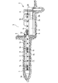
本発明の装置によれば、凹所(溝)3から始めて、穿孔2を土壌中に堀さくする。この目的のために凹所3中に押し引きユニット4を配設する。このユニットの固定台架5は、土壌1の壁に押圧板6を介して支持され、1以上の土壌アンカー7を介して保持されている。台架5に油圧ピストンシリンダユニット8が配設してあり、キャリッジ(可動体)9を直線上において往復動させることができる。キャリッジ9中の複数対の案内ボルト10は、ボーリングロッドのロッド部分15を案内するために用いられる。別のロッド部分14は、キャリッジ9中に保持されたロッド部分14に結合されている。複数のロッド部分14から成るロッドを介してボーリング端13を土壌中に圧入することによって、穿孔2が形成される。
【0030】
ロッド部分14は、横壁(ないし横バー)15及び平行桁在18とによって、はしご状に形成されている。
【0031】
各々のロッド部分14の一端に連結ヘッド19が配設してあり、この連結ヘッド19は、隣接したロッド部分14の最後から2番目の横壁及び最後の横壁17と共働する。連結ヘッド19は最後の横壁17を掴むための切欠20を備えている。連結ヘッド19のノーズ端(係合突部)21は、最後から2番目の横壁16の切欠24に係合し、ノーズ端(係合突部)22は、最後の横壁17の切欠25に係合する。
【0032】
複数のロッド部分14から成る、ボーリング端13を備えたロッドを土壌中に圧入することによって、穿孔2を、図1に示すように形成するには、キャリッジ9の押し込み運動に際して、横壁15の後部を掴む(当接押圧する)ことによって、複数のロッド部分14から成るロッドを土壌中に圧入するように、キャリッジ9に連結された爪片(下部ストッパ)11を配設する。この圧入運動の間に、前記ノーズ端21、22は、ロッド部分14の間に、押込み剛性を示す結合が確保されるように、切欠24、25中に配される。
【0033】
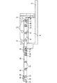
図2において、押し引きユニット4は、その前方への送り(圧入)行程の終端において図示されている。キャリッジが油圧ピストンシリンダユニット8を介して、図1に示した位置まで後退すると、押し引きユニット4の台架に配設された爪片(上部ストッパ)12は、継手ヘッド19の上部先端に係合して複数のロッド部分14から成るロッドを台架5と共に後退せしめる。
【0034】
爪片11、12は弾性ばね作用の下に、図1、2に示した位置に保持することができ、横壁15、16、17又は連結ヘッド19が通過する際(台架5が後退する際)にのみ後退することによって、図示した位置を後に(台架の前進運動時に)再び占めうるようになっている。爪片11、12を機械的、電気的又は液圧式に作動させることもできる。これによって最後から2番目の横壁16が、図1に示した位置において、押圧板6の少し前方に位置されるまで、ロッド部分14が土壌2中に圧入された時、上部の案内ボルト10を台架9から取除き、別のロッド部分14を、図4に示すように、先行するロッド部分14と連結する。そのためには、連結しようとするロッド部分14の連結ヘッド19のノーズ端21を、傾斜した状態で、最後から2番目の横壁16と最後の横壁17との間の横孔26に通した後、図1、2に示した位置まで、先行するロッド部分14と面一(一直線の整列位置)になるように回動させる。次に、上部案内ボルト10を再びキャリッジ9に挿通し、このロッド部分14も再び土壌2中にほぼ挿入するまで、押し引きユニット4による間欠的な送り(圧入)操作を継続する。
【0035】
ノーズ端21、22は、その時々の最後のロッド部分14に作用する送り作動の結果として、最後から2番目の横壁16及び最後の横壁17の切欠24、25中に進入することによって、押込み剛性を示す結合がロッド部分14の間に確実に実現される。
【0036】
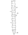
図3に示すように、古い配管28を新しい配管31に代えるには、最初に、1つのロッドを形成するように順次互に結合されるロッド部分14を、1つの立て孔(シャフト、マンホール)27から、古い配管28を経て、図示しない隣接した導孔まで押込む。次に、押し引きユニット4の領域中において立て孔27中に存在するロッド部分14が、キャリッジに送りをかけるための油圧ピストンシリンダユニット8によって立て孔27中に引込まれる間に、最後のロッド部分14の連結ヘッド19に破壊ヘッド29が連結される。このようにして古い配管28は破壊ヘッド29によって破壊される。それと同時に、拡開された穿孔30が形成され、破壊ヘッド29に連結された引張り導入ロール31(新しい配管となる)が、穿孔30中に導入される。
【0037】
複数のロッド部分14から成るロッドの引込みを可能とするために、爪片11、12は、図1の状態に対して180°回転させて(逆向きに)配置される。即ち、台架の前進時には斜面を介して後退可能であるが、台架の後進時には爪片11、12はストッパとして機能し、ロッドを後方へ引張り出すよう作用する。
【0038】
破壊ヘッド29には、古い配管28の破壊を支援するため、圧力媒体によって駆動される穿孔ラム装置32を配設してもよい。この穿孔ラム装置32には圧力媒体が引張り導入ロール31中の圧力媒体配管33を介して供給される。穿孔ラム装置32の打撃によって古い配管28のすみやかな破壊が達せられる。
【0039】
穿孔ラム装置32に代えて、又はそれと共働するように、破壊ヘッド29に取付けうる切刃を用いることができる。これらの切刃は、径方向運動によって、局所的に強化された大きな力を古い配管28に作用させてこれを破断させる。
【0040】
図5、6に示したロッド部分34は、はしご状にでなく、中実に形成された横方向の突起35を備えている。これらの突起には、図1〜4の爪片11、12と同様の爪片(突部)が送り作用を与えるために係合することができる。
【0041】
各々のロッド部分34の一端には、切欠43及びノーズ端44、45を備えた連結ヘッド42が配設されている。ロッド部分34の他端には、横壁(横バー)38、39によって画定された横孔37があるので、連結ヘッド42は、この横孔37により傾動して、別の連結ヘッド34に連結されることができる。
【0042】
ノーズ端44、45は、次に切欠40、41に係合するので、この実施例においても、押込み耐性を示す連結が達せられる。
【0043】
図7〜9には、ロッド部分48の間の、押込み耐性を示す結合が図示されている。これらのロッド部分は、はしご状に形成されているが、互に平行な縦桁材と、隣接した切欠50のバヨネット継手ヘッド51、52とのみが図示されている。バヨネット継手ヘッド51は、ロッド部分48の長手方向に延びる継目板として形成される。この継目板の厚みは、ロッド部分48の半幅にほぼ等しい。バヨネット継手ヘッド51の先端には、ロッド部分48の相補形状のノーズ端(突起部)54と共働する切欠53が形成されている。バヨネット継手ヘッド51は、横ピン55を有し、この横ピン55は、バヨネット継手ヘッド52の横孔56と共働する。
【0044】
図7に示すように、バヨネット継手ヘッド51、52は、互いに相補形状に形成されているので、図8に示した状態において、横ピン55は、横孔56に挿通され、ロッド部分48は、揺動して、延在位置即ち面一(直線整列位置)の状態にもたらされ、そこでロックされる。
【0045】
横孔56を長孔として形成した場合、ロッド部分48に対する送り作用によって、僅かな相対的なずれを生ずることがあり、このずれによって、バヨネット継手ヘッド51、52の垂直面が互に突当るため、双方のロッド部分48が互に対し押込み剛性をもって結合される。
【0046】
図10、11に示したロッド部分57は、円形又は正方形の断面形状を有し、一端側には、円錐形の雄ねじ58が形成され、他端側には、円錐形の雌ねじを備えた内孔59が形成されている。ロッド部分57は、これにより、簡単な仕方で互に螺合され、押込み剛性を示す1つのロッドを形成する。押し引きユニットのロッド駆動用係合(連結)手段(爪片等)は、環状溝として形成された切欠60に係合することができる。環状溝の代りに、ロッド部分57の外面にらせん溝を形成してもよい。
【0047】
形状連結による係合要素が図12に示すように少くとも2つの径方向に可動の掴みグリップとして形成され、これらのグリップが押し引きユニットのロッドの先端の雄ねじ58と共働するようにした場合には、円錐形のねじによって互に結合されるロッド部分を完全に平滑に形成することができる。
【0048】
ロッドが個々のロッド部分から成るのでなく、1つのリンクチェーンから成る場合には、ドラムからそのチェーンを凹所(溝)3中もしくは立て孔27中又はその外側に展開させたり、その上に巻付けたりし、各々のロッド部分の取付けに要する作業の中断を不要とする。リンクチェーンの場合の送りは、直線上の駆動によっても、回転駆動によっても行いうる。個々のチェーンリンクの間の押込み剛性の連結は、チェーンリンクの結節(リンク)部分に軸方向の可動性がある場合に達せられ、互に隣接するチェーンリンクの相補形状の面は、圧入力が作用した場合に互に突当り、押込み剛性の結合が実現される。
【0049】
【発明の効果】
本願発明の第1の視点として、ロッドに対する形状連結による係合手段を備えた押し引きユニットを有することにより(請求項1の基本構成)、改良された土壌ボーリング装置が提供される。これにより、ロッドの押しに対しても引きに対しても適合し、押し引きユニットのすべりによるロッドの摩損を避けることができる。
【0050】
本発明の第2の視点として、ロッド部材間の引張り及び押込み剛性を有するロッド継手を介して互いに着脱自在に結合組立て可能なロッドが提供され、ロッドの押込み、引張りのいずれの操作にも適合可能なロッド手段が提供される。その実施形態としては、第1の視点における押し引きユニットに適合するロッドを提供するという利点がある。各従属請求項に記載の特徴は上記本発明の有利な具体的展開形態を示す。
【図面の簡単な説明】
【図1】押し引きユニットと、このユニットと駆動結合されたロッドとから成る、土壌穿孔形成用の装置を示す。
【図2】押し引きユニットと、このユニットと駆動結合されたロッドとを示す詳細な側面図である。
【図3】押し引きユニットと、このユニットと駆動結合されたロッドとから成る、古い配管を破壊するための装置を示す。
【図4】結合過程の間のロッド部分を示す。
【図5】互いに結合された別のロッド部分を示す上面図である。
【図6】図5によるロッド部分の側面図である。
【図7】互に結合される前の、更に別のロッド部分の上面図である。
【図8】図7によるロッド部分の、結合の間の状態を示す側面図である。
【図9】図7によるロッド部分の結合状態を示す。
【図10】更に別の実施例によるロッド部分の非結合状態を示す。
【図11】図10によるロッド部分の結合状態を示す。
【図12】ねじ部と共働する係合手段の詳図である。
【符号の説明】
4 押し引きユニット
14、34、48、57 ロッド部分(ロッド)
36、60 切欠
11、12 爪片(係合手段)[0001]
BACKGROUND OF THE INVENTION
The present invention relates to a soil boring device and a soil boring method , and more particularly, a soil boring device having a push-pull unit and a rod (Gestaenge) that is drivingly connected to the unit and guided through the soil boring or piping. About. This soil boring device further relates to a device for forming and expanding soil perforations and / or destroying old piping, as well as a device for laying new piping.
[0002]
[Prior art]
Forming and expanding soil drilling and / or destroying old pipes and laying new pipes can advance ram drilling tools that generate power or generate static pressure to drive the rod forward Or using a press or winch that retracts or retracts. The ram drilling device that generates power generates a large noise during operation, and the vibration causes damage to the environment, especially parallel external pipes or intersecting external pipes, and generates oil-containing exhaust that pollutes the environment. There is a defect.
[0003]
Presses and winches that operate with static pressure are difficult to handle, and a rod having indentation rigidity is operated only by pushing, or by a tensile action using a wire.
[0004]
The indentation rigid rod is required to be composed of a plurality of rod portions having a short length because the feeding device is usually operated from a recess (groove) or a vertical hole (shaft). As the rod part length corresponding to the diameter of the recess or the vertical hole is pressed into the soil or into the old pipe, the part piece requires an increase in the length of the rod. Since the vertical holes typically have an inner diameter of 1 m, it can often occur that the individual rod length is not longer than 80 cm.
[0005]
When using a wire winch to guide the expander through the wire through the existing soil drilling, this wire must first be passed through the soil drilling or existing piping, but this is because of the bending brittle wire. If it is difficult, for the time being.
[Problems to be solved by the invention]
[0006]
In order to press the rod into the soil via the pushing device, it is necessary to act on the rod directly, and for this purpose a clamping grip is used which acts on the outer surface of the rod.
[0007]
The application of force by the clamping grip is done by mechanical coupling, so that against the smooth surface of the rod, inevitably slip occurs when the resistance of the soil increases, thereby causing wear and even stronger slip. .
[0008]
When the rod is pulled or pushed through the old piping to break it, the dust attached to the rod further increases the wear on the clamping grip and the rod, so slipping occurs more easily.
[0009]
Conventional rods are provided with threaded joints, which are particularly sensitive to fouling. The same applies to a screw having a rough pitch. When the tensile load is high and the bending radius is small, the screw is likely to break. Another defect of threaded joints is that the screws need to be tightened or loosened about every 80 cm, and if the screw pitch is high, at least 7-10 rotations are required. In the case of a 100 m long rod, about 125 individual rods are required, and corresponding screw tightening times are required.
[0010]
The object of the present invention is, in the first aspect, to greatly improve the above-mentioned defects, adapt to both pushing and pulling of the rod, and avoid wear of the rod due to sliding of the pushing and pulling unit. Another object of the present invention is to provide a soil drilling device and a soil boring method of the type described at the beginning. It is another object of the second aspect of the present invention to realize a rod joint that is rigid in tension and push-in that enables individual rods to be connected with a small amount of operation.
[0011]
[Means for Solving the Problems]
In order to solve this problem, according to the first aspect of the present invention, there is provided a push-pull unit (4) and a rod (or
[0012]
In a second aspect of the present invention, a push-pull unit (4) and a rod (or
According to a third aspect of the present invention, there is provided a soil boring method, wherein the first rod portion is fed together with the push-pull unit through the ground, and the push-pull unit is at least one protrusion or notch of the first rod portion. The second rod portion is rotated so as to become a rigid body when it is pushed into the first rod portion (forms a rod assembly); Is performed by the coupling of the coupling means provided on the two rod parts, and the rod parts are rigid with respect to the indentation via the coupling means by being (mutually) rotated, tilted or oscillated. The coupled rod portions are released at a certain angle, the angle is an angle between the major axes of the rod portions, and the engaging means is the second rod portion. By at least one protrusion or notch and engagement of the head portion, soil boring method characterized by causing the second rod portion advances the ground is provided.
[0013]
Note that the reference numerals of the drawings attached to the claims are only for the purpose of helping understanding, and are not intended to be limited to the illustrated embodiments.
[0014]
DETAILED DESCRIPTION OF THE INVENTION
The engagement means of the shape connection (ie, the engagement method between the members via the shape ring portion, formschluessig) eliminates slippage when pushing or pulling the rod, so that the entire push-pull (drive) device is The ability is utilized and no extra wear occurs on the rod and engagement means. The rod may be formed as a threaded rod or in the form of a ladder with a lateral wall (hereinafter also abbreviated as “lateral wall”), and may have an annular groove or a spiral groove. The engaging means may be engaged as a gear with a threaded rod, engaged with a lateral wall of a ladder-shaped rod, or engaged with an annular groove or a spiral groove. It may consist of a locking element that engages the groove or acts on the lateral wall or projection.
[0015]
The rod or bar or push bar may be assembled from individual rod parts or formed as a link chain. The engaging means may also comprise a locking element that engages at least one protrusion or notch and can be driven linearly by a push-pull unit to be locked or disengaged, whereby the rod is thereby pushed. You may make it move continuously via the gear rotationally driven by the pulling unit, or intermittently move linearly by the push-pull unit.
[0016]
At least the tip of the rod that can be coupled to the push-pull unit by shape connection is provided with a screw, and the shape connection with the rod is realized even if the engaging means is locked to this screw.
[0017]
In order for the rod or link chain to be able to be pushed or pulled by the push-pull unit, the rod consists of a plurality of rod parts that can be coupled to the indentation stiffness by a shape connection to each other, or the link chain In addition, it is formed so that it is linked to the pull and has indentation rigidity.
[0018]
If the rod consists of individual rod parts which are joined together, each rod part advantageously has a transverse hole defined by a transverse wall at one end and a connecting head at the other end, The connecting head engages with the side hole of the mating rod part to be connected and grips one side wall, the notch for holding the other side wall, and the outer surface of the other side wall during feeding (pushing) operation. Have a nose end to grip.
[0019]
With such a kinematic joint head, the individual rod parts are joined to each other and disconnected from each other when fully penetrated into or withdrawn from the soil, so that time And a lot of labor is not required, and the feeding operation is not interrupted for a long time.
[0020]
Advantageously, each lateral wall is provided with a notch (or recess) shaped to fit the nose end that engages it.
[0021]
If each rod portion is formed in a ladder shape, the side holes may be located between the penultimate side wall and the last side wall forming a side wall, and the side wall is for the nose end May be provided with a notch. On the other hand, if the rod part is formed solid with a notch for the engagement means, with a regular spacing on at least one side, the transverse hole is arranged at one end of one rod part. The other end is provided with a joint head.
[0022]
According to another form of connecting the rod parts to each other, advantageously, the rod parts are provided with complementary bayonet joint heads at both ends thereof, the joint heads at the front outer end at approximately the half width of the rod parts. The rod portion has a complementary nose end parallel to the seam plate, and the rod portion has a horizontal pin on the longitudinal plate, and another (partner) rod portion. The seam plate is provided with a complementary lateral hole (relative to the lateral pin). The size of the perforation is notch at the position where the horizontal pins of one rod part are inserted and engaged with each other in the horizontal hole at the tilted position of the two rod parts and are extended. To be locked by a nose end that engages.
[0023]
As a result, when one rod part is fully pushed into the pipe or the pipe, the second rod part comes into contact with the other rod part at a tilt angle and is flush with the other rod part. Locked by swinging to the extended position. The same applies to the case of retracting the rod, and the fully pulled rod part is released from the lock to the other rod part by tilting.
[0024]
When the transverse pins are slidable in the direction of the longitudinal axis of the rod portion in the transverse hole, the bayonet joint heads engage with each other by pushing action, and each rod portion exhibits indentation rigidity by shape connection. So that they are joined together.
[0025]
When the push-pull unit has a drive element that can move in a straight line, and the rod has a threaded portion at a tip that can be coupled to the push-pull unit by a shape connection, the engagement (connection) means includes: It may consist of at least two gripping grips that are movable in the radial direction and mesh with the threaded portion.
[0026]
On the other hand, if the rod part is formed as a threaded rod, in the form of a ladder or with an annular or helical groove, the locking element connects the push-pull unit with the rod part or link chain in the driving direction, at least 1 It may consist of two laterally movable claw pieces (stopper protrusions).
[0027]
In this case, the push / pull unit movable on a straight line must perform a return stroke after the work stroke, but in this case the rod should not move, so this non-movable part is placed on the non-movable part of the push / pull unit. It is desirable to dispose a movable claw piece in the lateral direction that connects or tightens with the rod portion or link chain in a direction opposite to the drive direction.
[0028]
Next, preferred embodiments of the present invention will be described in more detail with reference to the drawings.
[0029]
【Example】
According to the apparatus of the present invention, starting from the recess (groove) 3, the
[0030]
The
[0031]
A connecting
[0032]
In order to form the
[0033]
In FIG. 2, the push-pull unit 4 is illustrated at the end of its forward feed (press-fit) stroke. When the carriage is retracted to the position shown in FIG. 1 via the hydraulic
[0034]
The
[0035]
The nose ends 21, 22 enter the
[0036]
As shown in FIG. 3, in order to replace the
[0037]
In order to be able to retract a rod composed of a plurality of
[0038]
The breaking
[0039]
A cutting edge that can be attached to the breaking
[0040]
The
[0041]
A connecting
[0042]
Since the nose ends 44 and 45 are then engaged with the
[0043]
7-9 illustrate the bond between the
[0044]
As shown in FIG. 7, the bayonet joint heads 51 and 52 are formed in a complementary shape to each other. Therefore, in the state shown in FIG. 8, the
[0045]
When the
[0046]
The
[0047]
FIG. 12 shows that the engagement element is formed as a grip grip which is movable in at least two radial directions as shown in FIG. 12, and these grips cooperate with the
[0048]
When the rod is not composed of individual rod parts but is composed of a single link chain, the chain is developed from the drum in the recess (groove) 3 or in the
[0049]
【The invention's effect】
As a first aspect of the present invention, an improved soil boring device is provided by having a push-pull unit provided with engagement means by shape connection to a rod (basic configuration of claim 1). Accordingly, the rod is adapted to both the pushing and the pulling of the rod, and the rod can be prevented from being worn by the sliding of the pushing and pulling unit.
[0050]
As a second aspect of the present invention, a rod that can be detachably coupled and assembled via a rod joint having tension and pushing rigidity between rod members is provided, and can be adapted to both pushing and pulling operations of the rod. Rod means are provided. The embodiment has the advantage of providing a rod that fits the push-pull unit in the first viewpoint. The features of the subclaims show advantageous specific developments of the invention.
[Brief description of the drawings]
FIG. 1 shows a device for soil drilling comprising a push-pull unit and a rod drive-coupled to this unit.
FIG. 2 is a detailed side view showing a push-pull unit and a rod that is drivingly coupled to the unit.
FIG. 3 shows an apparatus for breaking old piping consisting of a push-pull unit and a rod drive-coupled to this unit.
FIG. 4 shows the rod portion during the coupling process.
FIG. 5 is a top view of another rod portion coupled together.
6 is a side view of the rod part according to FIG. 5;
FIG. 7 is a top view of yet another rod portion before being joined together.
8 is a side view showing the state of the rod part according to FIG. 7 during coupling.
9 shows the connecting state of the rod part according to FIG. 7;
FIG. 10 shows the uncoupled state of the rod portion according to yet another embodiment.
11 shows the connecting state of the rod part according to FIG.
FIG. 12 is a detailed view of the engaging means that cooperates with the threaded portion.
[Explanation of symbols]
4 Push-
36, 60
Claims (20)
該押し引きユニットと駆動結合されるロッド(14、34、48、57)であって、前記ロッドは、複数のロッド部分を含み、前記複数のロッド部分同士は、回転、傾動ないし揺動されることにより結合手段を介して押込みに対して剛体状になるよう結合され、前記結合された前記ロッド部分同士はある角度で結合が解除され、前記角度は前記ロッド部分の長軸同士間の角度である、前記ロッドと、
前記ロッドに設けられた少なくとも一つの突起(15、35)又は切欠(36、60)と、
前記ロッド上の前記少なくとも一つの前記突起(15、35)又は前記切欠(36、60)と確実に係合する、前記押し引きユニット(4)に設けられた係合手段(11、12)と、
を有する土壌ボーリング装置。A push-pull unit (4);
A rod (14, 34, 48, 57) that is drivingly coupled to the push-pull unit , the rod including a plurality of rod portions, and the plurality of rod portions are rotated, tilted, or rocked. Accordingly, the rod parts are coupled to each other by a coupling means so as to be rigid, and the coupled rod parts are released from each other at an angle, and the angle is an angle between the major axes of the rod parts. The rod,
At least one protrusion (15, 35) or notch (36, 60) provided on the rod;
Engagement means (11, 12) provided in the push-pull unit (4) for positively engaging the at least one protrusion (15, 35) or the notch (36, 60) on the rod; ,
Soil boring equipment.
該押し引きユニットと駆動結合されるロッド(14、34、48、57)であって、前記ロッドは、複数のロッド部分を含み、前記複数のロッド部分同士は、回転、傾動ないし揺動されることにより結合手段を介して押込みに対して剛体状になるよう結合され、前記結合された前記ロッド部分同士はある角度で結合が解除され、前記角度は前記ロッド部分の長軸同士間の角度又は前記ロッド部分同士の相対的な回転角度である、前記ロッドと、 前記ロッドに設けられた少なくとも一つの突起(15、35)又は切欠(36、60)と、
前記ロッド上の前記少なくとも一つの前記突起(15、35)又は前記切欠(36、60)と非回転な方式で確実に係合する、前記押し引きユニット(4)に設けられた係合手段(11、12)と、
を有する土壌ボーリング装置。A push-pull unit (4);
A rod (14, 34, 48, 57) drivingly coupled to the push-pull unit, wherein the rod includes a plurality of rod portions, and the plurality of rod portions are rotated, tilted or oscillated. Thus, the rod portions are coupled to each other by a coupling means so as to be rigid, and the coupled rod portions are decoupled at an angle, and the angle is an angle between the major axes of the rod portions or The rod and the at least one protrusion (15, 35) or notch (36, 60) provided on the rod, the relative rotation angle between the rod portions ;
Engagement means provided in the push-pull unit (4) that securely engages the at least one projection (15, 35) or notch (36, 60) on the rod in a non-rotating manner. 11, 12)
Soil boring equipment.
該バヨネット継手ヘッドは、
ほぼロッド部分(48)の半幅に対応する長目の継目板と、
前記長目の継目板の前方外側端に設けられた凹部及び前記ロッド部分に設けられ前記継目板と平行に延在する相補形状のノーズ端(54)と、
一方の前記ロッド部分の前記長目の継目板に設けられた横ピン及び他方の前記ロッド部分の前記継目板の外側端に相補形状の横孔(56)と、を有し、
前記横孔は、前記両者のロッド部分がある角度になり、前記ノーズ端が前記凹部と係合して、該両者のロッド部分が面一の状態で結合して延在したとき、前記一方のロッド部分(48)の前記横ピン(55)が、前記他方のロッド部分の前記横孔に係合可能であるような寸法であることを特徴とする請求項1又は2記載の土壌ボーリング装置。The coupling means has a complementary bayonet joint head (51, 52) at each end,
The bayonet joint head is
A long seam plate substantially corresponding to the half width of the rod portion (48);
A recess provided at the front outer end of the long seam plate and a complementary nose end (54) provided in the rod portion and extending in parallel with the seam plate;
A lateral pin provided on the long seam plate of one of the rod portions and a complementary lateral hole (56) at the outer end of the seam plate of the other rod portion;
The lateral hole has a certain angle when both of the rod portions are engaged, the nose end engages with the recess, and the rod portions of the both extend in a flush state. 3. A soil boring device according to claim 1 or 2 , characterized in that the transverse pin (55) of the rod part (48) is dimensioned to be engageable with the transverse hole of the other rod part.
地中を押し引きユニットと共に第1のロッド部分を送り、前記押し引きユニットは前記第1のロッド部分の少なくとも一つの突起又は切欠と係合する確実な係合手段を有し、
第2のロッド部分を回動させて前記第1のロッド部分と押し込まれた際に剛体となるよう結合し、前記結合は2つの前記ロッド部分に設けられた結合手段同士の結合によって行われ、前記ロッド部分同士は、回転、傾動ないし揺動されることにより前記結合手段を介して押込みに対して剛体状になるよう結合され、前記結合された前記ロッド部分同士はある角度で結合が解除され、前記角度は前記ロッド部分の長軸同士間の角度であり、
前記係合手段が前記第2のロッド部分の少なくとも一つの突起又は切欠と係合することによって、第2のロッド部分を地中を前進させることを特徴とする土壌ボーリング方法。Soil boring method,
Feeding the first rod portion with the push-pull unit through the ground, the push-pull unit having positive engagement means for engaging with at least one protrusion or notch of the first rod portion;
When the second rod portion is rotated and coupled with the first rod portion to become a rigid body, the coupling is performed by coupling of coupling means provided on the two rod portions, The rod parts are coupled to form a rigid body against the push-in via the coupling means by rotating, tilting or swinging, and the coupled rod parts are decoupled at an angle. The angle is an angle between the major axes of the rod portions,
A soil boring method, wherein the engaging means engages at least one protrusion or notch of the second rod portion to advance the second rod portion through the ground.
Applications Claiming Priority (2)
| Application Number | Priority Date | Filing Date | Title |
|---|---|---|---|
| DE19608980.8 | 1996-03-08 | ||
| DE19608980A DE19608980C2 (en) | 1996-03-08 | 1996-03-08 | Device for drilling in the ground |
Publications (2)
| Publication Number | Publication Date |
|---|---|
| JPH1018772A JPH1018772A (en) | 1998-01-20 |
| JP3703936B2 true JP3703936B2 (en) | 2005-10-05 |
Family
ID=7787604
Family Applications (1)
| Application Number | Title | Priority Date | Filing Date |
|---|---|---|---|
| JP07268497A Expired - Lifetime JP3703936B2 (en) | 1996-03-08 | 1997-03-10 | Soil boring device and soil boring method |
Country Status (4)
| Country | Link |
|---|---|
| US (1) | US5980157A (en) |
| EP (1) | EP0794315B1 (en) |
| JP (1) | JP3703936B2 (en) |
| DE (1) | DE19608980C2 (en) |
Families Citing this family (37)
| Publication number | Priority date | Publication date | Assignee | Title |
|---|---|---|---|---|
| DE19849611C1 (en) * | 1998-10-28 | 2000-03-09 | Tracto Technik | Production of ground bores and-or destruction of old pipe conduits underground |
| DE19814232C1 (en) * | 1998-03-30 | 1999-10-28 | Tracto Technik | Production of ground bores and-or destruction of old pipe conduits underground |
| US6238141B1 (en) | 1998-03-30 | 2001-05-29 | Tracto-Technik-Paul Schmidt Spezialmaschinen | Apparatus for static underground drilling |
| DE19817873C2 (en) | 1998-04-22 | 2003-07-31 | Tracto Technik | Method and device for trenchless laying of pipes in the ground |
| DE19817872C2 (en) * | 1998-04-22 | 2002-08-08 | Tracto Technik | expander |
| DE19831190C1 (en) | 1998-07-11 | 1999-10-28 | Tracto Technik | Appliance for dividing subterranean pipes and laying of new ones etc. |
| US6364036B1 (en) | 1999-02-23 | 2002-04-02 | Tracto-Technik-Paul Schmidt Spezialmaschinen | Automatic rod assembly |
| DE19922813C2 (en) * | 1999-02-23 | 2001-03-29 | Tracto Technik | Automatic boom |
| DE19918530B4 (en) * | 1999-04-23 | 2006-07-06 | Wolfgang Schmidt E.K. | Coupling for connecting two sections of a drill string |
| DE19920395C1 (en) * | 1999-05-04 | 2000-07-06 | Tracto Technik | Equipment for widening earth holes and/or for destruction of pipe conduits laid in earth together with laying new pipe conduits |
| DE10065533B4 (en) * | 2000-12-29 | 2006-07-13 | Tracto-Technik Gmbh | Linkage coupling for rod sections with a media channel |
| US6682264B1 (en) * | 2002-02-26 | 2004-01-27 | Ina Acquisition Corp. | Method of accurate trenchless installation of underground pipe |
| DE102004032356A1 (en) * | 2004-07-03 | 2006-02-09 | Tracto-Technik Gmbh | System for working in underground pipes using a compact servo driven flexible thrust chain at angles to the pipe from inside an inspection shaft |
| DE102005039790B3 (en) * | 2005-08-22 | 2007-01-04 | Tracto-Technik Gmbh | Method for renovation of transport duct located underground, comprises use of old duct for accommodation of rods |
| US20070048090A1 (en) * | 2005-08-31 | 2007-03-01 | Wentworth Steven W | Method and apparatus for installation of underground ducts |
| US7914233B2 (en) * | 2006-03-10 | 2011-03-29 | Harr Technologies Llc | Method and apparatus for installing an underground pipe |
| US20070245516A1 (en) * | 2006-04-19 | 2007-10-25 | Wentworth Steven W | Rod pushing and pulling machine |
| DE102007016823A1 (en) * | 2007-04-05 | 2008-11-06 | Tracto-Technik Gmbh & Co. Kg | Drilling System |
| JP5713670B2 (en) * | 2007-04-05 | 2015-05-07 | トラクト−テヒニーク ゲゼルシャフト ミット ベシュレンクテル ハフツング ウント コンパニー コマンディートゲゼルシャフトTRACTO−TECHNIK GmbH & Co. KG | Rod joint with sacrificial element |
| DE102007016824B4 (en) * | 2007-04-05 | 2011-04-28 | Tracto-Technik Gmbh & Co. Kg | Eindrehkupplung |
| DE102007016822B4 (en) | 2007-04-05 | 2009-01-15 | Tracto-Technik Gmbh & Co. Kg | Linkage coupling with pin |
| DE202008012210U1 (en) | 2008-09-12 | 2008-11-27 | Tracto-Technik Gmbh & Co. Kg | threaded connection |
| DE102008047060B4 (en) * | 2008-09-12 | 2011-05-26 | Tracto-Technik Gmbh & Co. Kg | threaded connection |
| DE102009038058A1 (en) | 2009-08-19 | 2011-02-24 | TERRA AG für Tiefbautechnik | Device and method for moving a working fluid in the ground |
| DE102011100186A1 (en) | 2011-05-02 | 2012-11-08 | Tracto-Technik Gmbh & Co. Kg | "Rod and device for trenchless rehabilitation of pipelines" |
| DE102011107348A1 (en) | 2011-06-29 | 2013-01-03 | Tracto-Technik Gmbh & Co. Kg | "Connection device" |
| US10030683B2 (en) | 2011-12-13 | 2018-07-24 | Peak Well Systems Pty Ltd | Connector |
| JP5887184B2 (en) * | 2012-03-30 | 2016-03-16 | 東邦瓦斯株式会社 | Non-cutting new pipe laying method and laying equipment |
| DE102012025187A1 (en) | 2012-12-27 | 2014-07-03 | Tracto-Technik Gmbh & Co. Kg | connecting device |
| EA027243B1 (en) * | 2015-01-13 | 2017-07-31 | Общество С Ограниченной Ответственностью "Мемпэкс" | Method for no-dig replacement of underground pipelines and installation for implementing the same |
| CN105064913B (en) * | 2015-07-27 | 2017-07-28 | 桂林理工大学 | A kind of main frame assembly of Geotechnical Engineering rig |
| CN106401455A (en) * | 2016-09-18 | 2017-02-15 | 山西省交通科学研究院 | Auxiliary robot device for engineering pipeline construction |
| CN110485470B (en) * | 2019-08-08 | 2021-05-04 | 郑州安源工程技术有限公司 | Rectangular working well with pre-arranged jacking pipe door opening and sliding type rear wall in water-rich stratum and construction method of rectangular working well |
| DE102020005981A1 (en) | 2020-09-30 | 2022-03-31 | Tracto-Technik Gmbh & Co. Kg | Drive and method for operating a drive of an earth boring device |
| DE102021000497A1 (en) | 2021-02-02 | 2022-08-04 | Tracto-Technik Gmbh & Co. Kg | Arrangement of an earth boring device, method of operating an earth boring device and use of an arrangement of an earth boring device |
| EP4403740A1 (en) | 2023-01-17 | 2024-07-24 | TRACTO-TECHNIK GmbH & Co. KG | Threaded connection |
| EP4403741A1 (en) | 2023-01-17 | 2024-07-24 | TRACTO-TECHNIK GmbH & Co. KG | Threaded connection |
Family Cites Families (25)
| Publication number | Priority date | Publication date | Assignee | Title |
|---|---|---|---|---|
| DE317300C (en) * | ||||
| DE166028C (en) * | ||||
| DE474493C (en) * | 1929-04-03 | Georg Butz | Support rods and feed device for drilling machines for drilling up holes | |
| BE527075A (en) * | ||||
| US1179491A (en) * | 1915-06-22 | 1916-04-18 | Charles D Ammon | Pipe-pilot. |
| US1210187A (en) * | 1916-05-29 | 1916-12-26 | James E Marquiss | Conduit-forming device. |
| US1872523A (en) * | 1929-11-13 | 1932-08-16 | Connell And Sweeney O | Earth piercing device |
| US1916466A (en) * | 1932-07-29 | 1933-07-04 | John W Eckles | Pipe pusher |
| FR819203A (en) * | 1936-06-19 | 1937-10-13 | Bonnet Et Fils | Horizontal drilling rig |
| DE717535C (en) * | 1939-06-10 | 1942-02-17 | Frankfurter Maschb Ag Vormals | Rock percussion drill with exchangeable drill bit |
| US2693345A (en) * | 1950-01-10 | 1954-11-02 | James A Martin | Earth-boring apparatus |
| US2788234A (en) * | 1952-05-19 | 1957-04-09 | Cedric J Doyle | Coupling unit |
| US2823898A (en) * | 1954-08-27 | 1958-02-18 | James M Bankston | Tunnel forming apparatus |
| US3001761A (en) * | 1958-08-22 | 1961-09-26 | Frank C Moessner | Conduit rod pusher |
| US2964296A (en) * | 1959-02-13 | 1960-12-13 | Kenneth C Cluff | Feed mechanism for drilling apparatus |
| US3391543A (en) * | 1966-06-23 | 1968-07-09 | Soil Sampling Service Inc | Means and technique for installing elongated rods in unstable earth formations |
| US4062412A (en) * | 1976-01-29 | 1977-12-13 | The United States Of America As Represented By The Secretary Of The Interior | Flexible shaft drilling system |
| DE3533995A1 (en) * | 1985-09-24 | 1987-04-16 | Tracto Technik | RAMM DRILLING DEVICE WITH IMPACT PISTON |
| JPS6480698A (en) * | 1987-09-24 | 1989-03-27 | Tokyo Gas Co Ltd | Automatic supply and recovery device for pipe |
| JPH01250597A (en) * | 1987-12-31 | 1989-10-05 | Kyokuto Kaihatsu Kogyo Co Ltd | Replacement of buried piping |
| JPH01192993A (en) * | 1988-01-27 | 1989-08-03 | Furukawa Co Ltd | Rod-fall prevention device |
| US5213449C1 (en) * | 1991-07-08 | 2001-07-03 | T Richard Morris | Apparatus for inserting wick drains into the earth |
| DE4220430C2 (en) * | 1992-06-24 | 1994-09-22 | Tracto Technik | Method and device for making an earth borehole |
| JPH0642539A (en) * | 1992-07-23 | 1994-02-15 | Kobe Steel Ltd | Shaft coupling structure |
| JPH089269Y2 (en) * | 1993-04-23 | 1996-03-13 | 株式会社亀山 | Bowling rod |
-
1996
- 1996-03-08 DE DE19608980A patent/DE19608980C2/en not_active Expired - Lifetime
-
1997
- 1997-02-17 EP EP97102510A patent/EP0794315B1/en not_active Expired - Lifetime
- 1997-02-24 US US08/805,240 patent/US5980157A/en not_active Expired - Lifetime
- 1997-03-10 JP JP07268497A patent/JP3703936B2/en not_active Expired - Lifetime
Also Published As
| Publication number | Publication date |
|---|---|
| EP0794315B1 (en) | 2003-07-02 |
| DE19608980A1 (en) | 1997-09-11 |
| EP0794315A1 (en) | 1997-09-10 |
| US5980157A (en) | 1999-11-09 |
| DE19608980C2 (en) | 1998-05-07 |
| JPH1018772A (en) | 1998-01-20 |
Similar Documents
| Publication | Publication Date | Title |
|---|---|---|
| JP3703936B2 (en) | Soil boring device and soil boring method | |
| US6474701B1 (en) | Tubing connector | |
| EP1755832B1 (en) | Improvements to hydraulic tensioning jacks | |
| US7384214B2 (en) | Pipe splitter and method | |
| KR20120130170A (en) | Method for replacing a tunnel boring machine disk cutter handling device and disk cutter suited to such a method | |
| EP0681085B1 (en) | Coiled tubing connector | |
| CA2616055A1 (en) | System and methods for tubular expansion | |
| US20080196556A1 (en) | Cam operated jaw force intensifier for gripping a cylindrical member | |
| US8540458B2 (en) | Center hole ram cable puller | |
| JP4560060B2 (en) | Pile head gripping device for steel pipe pile and construction method of steel pipe pile | |
| JP3336430B2 (en) | Vertical joints for steel pipe sheet piles | |
| JP5090016B2 (en) | Clamp | |
| US4329077A (en) | Underground pipe pusher | |
| US20030044237A1 (en) | Trenchless water pipe replacement device and method | |
| JPH0762968A (en) | Fitting/removing device for tube body | |
| CA2404336C (en) | A wrench for use with drilling apparatus | |
| JP2009167753A (en) | Pull-out method of anchor bolt and pull-out device | |
| AU2005201610B2 (en) | Method and device for engaging a bore | |
| US6263988B1 (en) | Downhole drill system and de-coupling assembly | |
| JP6535460B2 (en) | Pipe pulling jig used for non-widening AGF method | |
| JP4686313B2 (en) | Propulsion device | |
| JP4347149B2 (en) | Mechanical joint of a longitudinal connection device for piles with means for preventing looseness | |
| CN211240108U (en) | Device for fastening heating pipe and flange plate | |
| GB2184050A (en) | Detachable connection between cylindrical parts | |
| CN220080011U (en) | Get stake pile driver all-in-one |
Legal Events
| Date | Code | Title | Description |
|---|---|---|---|
| A521 | Request for written amendment filed |
Free format text: JAPANESE INTERMEDIATE CODE: A523 Effective date: 19970418 |
|
| A521 | Request for written amendment filed |
Free format text: JAPANESE INTERMEDIATE CODE: A523 Effective date: 19970424 |
|
| A521 | Request for written amendment filed |
Free format text: JAPANESE INTERMEDIATE CODE: A523 Effective date: 20040309 |
|
| A621 | Written request for application examination |
Free format text: JAPANESE INTERMEDIATE CODE: A621 Effective date: 20040309 |
|
| A871 | Explanation of circumstances concerning accelerated examination |
Free format text: JAPANESE INTERMEDIATE CODE: A871 Effective date: 20040309 |
|
| A975 | Report on accelerated examination |
Free format text: JAPANESE INTERMEDIATE CODE: A971005 Effective date: 20040514 |
|
| A131 | Notification of reasons for refusal |
Free format text: JAPANESE INTERMEDIATE CODE: A131 Effective date: 20040824 |
|
| A601 | Written request for extension of time |
Free format text: JAPANESE INTERMEDIATE CODE: A601 Effective date: 20041109 |
|
| A602 | Written permission of extension of time |
Free format text: JAPANESE INTERMEDIATE CODE: A602 Effective date: 20041112 |
|
| A521 | Request for written amendment filed |
Free format text: JAPANESE INTERMEDIATE CODE: A523 Effective date: 20050224 |
|
| TRDD | Decision of grant or rejection written | ||
| A01 | Written decision to grant a patent or to grant a registration (utility model) |
Free format text: JAPANESE INTERMEDIATE CODE: A01 Effective date: 20050705 |
|
| A61 | First payment of annual fees (during grant procedure) |
Free format text: JAPANESE INTERMEDIATE CODE: A61 Effective date: 20050721 |
|
| R150 | Certificate of patent or registration of utility model |
Free format text: JAPANESE INTERMEDIATE CODE: R150 |
|
| FPAY | Renewal fee payment (event date is renewal date of database) |
Free format text: PAYMENT UNTIL: 20080729 Year of fee payment: 3 |
|
| FPAY | Renewal fee payment (event date is renewal date of database) |
Free format text: PAYMENT UNTIL: 20090729 Year of fee payment: 4 |
|
| FPAY | Renewal fee payment (event date is renewal date of database) |
Free format text: PAYMENT UNTIL: 20100729 Year of fee payment: 5 |
|
| FPAY | Renewal fee payment (event date is renewal date of database) |
Free format text: PAYMENT UNTIL: 20110729 Year of fee payment: 6 |
|
| FPAY | Renewal fee payment (event date is renewal date of database) |
Free format text: PAYMENT UNTIL: 20110729 Year of fee payment: 6 |
|
| FPAY | Renewal fee payment (event date is renewal date of database) |
Free format text: PAYMENT UNTIL: 20120729 Year of fee payment: 7 |
|
| FPAY | Renewal fee payment (event date is renewal date of database) |
Free format text: PAYMENT UNTIL: 20120729 Year of fee payment: 7 |
|
| FPAY | Renewal fee payment (event date is renewal date of database) |
Free format text: PAYMENT UNTIL: 20130729 Year of fee payment: 8 |
|
| R250 | Receipt of annual fees |
Free format text: JAPANESE INTERMEDIATE CODE: R250 |
|
| S531 | Written request for registration of change of domicile |
Free format text: JAPANESE INTERMEDIATE CODE: R313531 |
|
| R350 | Written notification of registration of transfer |
Free format text: JAPANESE INTERMEDIATE CODE: R350 |
|
| R250 | Receipt of annual fees |
Free format text: JAPANESE INTERMEDIATE CODE: R250 |
|
| R250 | Receipt of annual fees |
Free format text: JAPANESE INTERMEDIATE CODE: R250 |
|
| R250 | Receipt of annual fees |
Free format text: JAPANESE INTERMEDIATE CODE: R250 |
|
| EXPY | Cancellation because of completion of term |