JP3703740B2 - Fixing method of steel pillar - Google Patents
Fixing method of steel pillar Download PDFInfo
- Publication number
- JP3703740B2 JP3703740B2 JP2001192617A JP2001192617A JP3703740B2 JP 3703740 B2 JP3703740 B2 JP 3703740B2 JP 2001192617 A JP2001192617 A JP 2001192617A JP 2001192617 A JP2001192617 A JP 2001192617A JP 3703740 B2 JP3703740 B2 JP 3703740B2
- Authority
- JP
- Japan
- Prior art keywords
- iron pillar
- steel pipe
- sleeve hole
- fixed
- fixing
- Prior art date
- Legal status (The legal status is an assumption and is not a legal conclusion. Google has not performed a legal analysis and makes no representation as to the accuracy of the status listed.)
- Expired - Fee Related
Links
Images


Landscapes
- Foundations (AREA)
Description
【0001】
【産業上の利用分野】
本発明は、低層の住宅その他の構造物の支柱として適する鉄柱の固定方法に関する。
【0002】
【従来の技術】
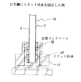
図1は、従来の鉄柱の固定構造を示す側面図である。1は鉄柱であり、断面形状は、図示のような丸形鋼管から、角型鋼管やH型鋼など、色々な形状が採用されている。
【0003】
図示の鉄柱1の下端には、予め所定の位置にボルト孔を開けたベースプレート2を溶接固定してある。3は鉄柱1とベースプレート2との間に溶接固定してある補強用のリブである。
【0004】
4は基礎コンクリートであり、その中にアンカーボルト5が埋め込まれている。このアンカーボルト5は、正確に位置出しした状態で、基礎コンクリート4中に埋め込まれている。したがって、鉄柱1を基礎コンクリート4の上に立て、アンカーボルト5の上端のオネジ部をベースプレート2から突出させた状態で、ナット6を締めつけると、鉄柱1を基礎コンクリート4上に固定できる。
【0005】
GLが地表面であり、約800cmの深さまで掘り下げて基礎栗石7を敷き、その上に捨てコンクリート8を打設し、その上に基礎コンクリート4を打設する。基礎コンクリート4を打設する際は、ベースプレート2に代わる位置決めプレートに予めアンカーボルト5をナット6で固定した状態で、各アンカーボルト5を捨てコンクリート8上の穴に位置決めした状態で、基礎コンクリート4を打設する。
【0006】
このようにして、予め各アンカーボルト5の位置を正確に位置決めしてあるが、それでも鉄柱1のベースプレート2のボルト穴とアンカーボルト5の上端とを位置合わせすることは困難であり、各アンカーボルト5の上端のオネジ部をベースプレート2の穴に挿入することは極めて困難を来すのが通常である。
【0007】
こうしてアンカーボルト5のオネジ部とベースプレート2のボルト穴とを位置合わせしてから、間にライナー9を挟み、ナット6を締めつける。
【0008】
【発明が解決しようとする課題】
各アンカーボルト5のオネジ部の位置とベースプレート2のボルト穴との位置ずれの許容範囲は±1mm程度である。したがって、このような許容誤差の範囲内で施工することは作業性が悪く、非能率的である。
【0009】
また、アンカーボルト5と鉄柱1の下部との間の連結部における強度が最も弱いため、横揺れの原因となる。そのため、隣接する鉄柱や梁との間に筋交いやブレースを用いて補強する必要が生じ、構造が複雑化するほか、工数の増加により施工コストも高くなる。
【0010】
したがって、筋交いやブレースを採用できないような構造の場合は、特に支障を来すことになる。
【0011】
本発明の技術的課題は、このような問題に着目し、鉄柱を立てて固定する場合に、非能率な位置合わせ作業を軽減でき、しかも横揺れも低減可能な堅牢な固定方法を実現することにある。
【0012】
【課題を解決するための手段】
本発明の技術的課題は次のような手段によって解決される。請求項1は、鉛直方向のスリーブ穴を有する鉄筋入りコンクリート基礎を形成した後、
脚部に水平方向の突出部を有する鉄柱の前記脚部を前記スリーブ穴中に挿入して固定する鉄柱の固定方法において、
予め測定した位置に前記鉄柱の中心が来るように、前記スリーブ穴の上に、前記脚部を当てる当たり部材を釘付けして固定し、
次いで前記鉄柱を吊り上げてその脚部を前記スリーブ穴に挿入し、かつ前記当たり部材に前記脚部を当てた状態で、
前記脚部の左右両側面とスリーブ穴内面との間にクサビを打ち込んで、前記脚部の位置決めと仮固定を行い、
その後、前記スリーブ穴と前記脚部との間にコンクリートを打設し、脚部をスリーブ穴に固定することを特徴とする鉄柱の固定方法である。
【0013】
このように、鉛直方向のスリーブ穴を有する鉄筋入りコンクリート基礎を形成した後、脚部に水平方向の突出部を有する鉄柱の前記脚部を前記スリーブ穴中に挿入して固定する鉄柱の固定方法において、予め測定した位置に前記鉄柱の中心が来るように、前記スリーブ穴の上に、前記脚部を当てる当たり部材を釘付けして固定し、次いで前記鉄柱を吊り上げてその脚部を前記スリーブ穴に挿入し、かつ前記当たり部材に前記脚部を当てた状態で、前記脚部の左右両側面とスリーブ穴内面との間にクサビを打ち込んで、前記脚部の位置決めと仮固定を行い、その後、前記スリーブ穴と前記脚部との間にコンクリートを打設し、脚部をスリーブ穴に固定する方法を採っているため、従来のように予め埋設固定されるアンカーボルトの上端と鉄柱下端のベースプレートのボルト穴とを位置合わせできるような高精度の施工が不必要となる。その結果、作業性が良くなり、能率的に施工でき、工期の短縮による施工コストの低減を図ることができる。
【0014】
また、このように、鉄筋入りコンクリート造によって形成された鉛直方向のスリーブ穴の中に脚部を埋めて固定する鉄柱において、前記鉄柱の脚部に水平方向の突出部を有しているので、この突出部によって、コンクリートスリーブ穴中のコンクリートとの結合力が高まり、鉄柱の引き抜きおよび沈降方向の力に充分に耐えることができる。さらに、鉄柱自体の脚部が鉛直方向のスリーブ穴中に深く埋め込まれているので、鉄柱の横揺れが抑制され、従来のような筋交いやブレースが不要となる。したがって、筋交 いやブレースを採用不能な構造に特に有効である。
【0015】
請求項2は、前記鉄柱が、丸形鋼管、角型鋼管又はH型鋼であることを特徴とする請求項1に記載の鉄柱の固定方法である。このように、前記鉄柱として丸形鋼管、角型鋼管又はH型鋼を示したが、他の形状の鉄柱を用いてもよい。また、軽量型鋼や軽量H型鋼などを用いることもできる。
【0016】
請求項3は前記鉄柱が丸形鋼管又は角型鋼管であり、下端にカバープレートを溶接して、下端を塞いであることを特徴とする請求項1に記載の鉄柱の固定方法である。このように、丸形鋼管と角型鋼管の下端にカバープレートを溶接して下端の開口を塞いであるため、鉄柱をスリーブ穴の中に立てて固定した場合、カバープレートと水平方向の前記突出部との作用で、鉄柱の沈降を抑制できる。
【0017】
請求項4は、前記鉄柱がH型鋼であって、その脚部のみ、両側の空間に側板を溶接固定してあることを特徴とする請求項1に記載の鉄柱の固定方法である。このように、前記鉄柱がH型鋼の場合は、その脚部のみ、両側の空間に側板を溶接固定して補強し、変形防止を図っている。
【0018】
請求項5は、前記の水平方向の突出部が、鉄柱の脚部に、L字状の引っ掛かりを有するアンカー鉄筋を溶接固定することで形成されていることを特徴とする請求項1から請求項4までのいずれかの項に記載の鉄柱の固定方法である。このように、鉄柱の脚部とコンクリートとの結合力を確保するための水平方向の突出部が、鉄柱の脚部に、L字状の引っ掛かりを有するアンカー鉄筋を溶接固定することで形成されているため、水平方向の突出部を比較的簡易で堅牢な構造にでき、鉄柱資材を低コストで実現できる。
【0019】
請求項6は、前記の水平方向の突出部が、鉄柱の脚部に、スタッド状体を固定することで形成されていることを特徴とする請求項1から請求項4までのいずれかの項に記載の鉄柱の固定方法である。このように、鉄柱の脚部とコンクリートとの結合力を確保するための水平方向の突出部が、鉄柱の脚部に、スタッド状体を固定することで形成されているため、水平方向の突出部を比較的簡易で堅牢な構造にでき、鉄柱資材を低コストで実現できる。結果的に、鉄柱の固定方法を低コストで施工できる。
【0020】
【発明の実施の形態】
次に本発明による鉄柱の固定方法が実際上どのように具体化されるか実施形態を説明する。図2は丸形鋼管1を固定する場合の実施形態の平面図であり、図3は図2のA−A断面図である。
【0021】
1は丸形鋼管製の鉄柱であり、10はこの丸形鋼管1の脚部を挿入して埋め込むためのスリーブ穴である。スリーブ穴10は、鉄筋入りのコンクリート基礎11で形成されている。すなわち、約950cmの深さまで掘り下げて基礎栗石7を敷いてから捨てコンクリート8を打設し、その上に荷重受け部の鉄筋12aを敷きつめ、その上に筒状の鉄筋12bを配筋してから、コンクリートを打設することによって、深さ60cmのスリーブ穴10を形成する。
【0022】
コンクリート基礎11は、建設する構造物に応じたサイズとする。なお、スリーブ穴10の形成やコンクリート基礎11の外形の形成には、型枠を用いることは言うまでもない。
【0023】
このようにして形成したスリーブ穴10の中に丸形鋼管1の脚部を挿入して立てるが、脚部には水平方向の突出部を設けてある。すなわち、下端にL字状の引っ掛かりを有するアンカー鉄筋13を鉄柱1の脚部に溶接固定してある。このアンカー鉄筋13は、約30cmの長さの鉄筋13aの下端が外側にL字状に曲がっている。このL字状部13bは、立っている丸形鋼管1に対し、水平方向に例えば約5cmほど突出しているので、スリーブ穴10中にコンクリートを打設した場合、丸形鋼管1に対し抜け止めとして作用する。
【0024】
丸形鋼管1の場合は、このアンカー鉄筋13は、丸形鋼管1の脚部の外周に90度間隔に4か所程度配置すれば足りる。なお、アンカー鉄筋13の太さは、直径20mm程度で足りる。アンカー鉄筋13の固定は、2〜3か所程度を溶接すれば足りる。丸形鋼管1の下端にはカバープレートCpを溶接して、下端を塞いである。したがって、丸形鋼管1をスリーブ穴10中に立てて固定した場合、カバープレートCpとアンカー鉄筋13との作用で、丸形鋼管1の沈降を抑制できる。
【0025】
施工に際しては、前記のようにして形成したスリーブ穴10の中に丸形鋼管1の脚部を挿入する。次いで、予め測定した位置に丸形鋼管1の中心が来るように、測定した位置に当たり部材14を釘付けして固定する。次に、丸形鋼管1を吊り上げた状態で、この当たり部材14に丸形鋼管1の脚部を当てた状態で、左右からスリーブ穴10中にクサビ15、16を打ち込んで、丸形鋼管脚部の位置決めをすると共に仮固定する。
【0026】
この状態で、スリーブ穴10の中にコンクリートを打設し養生すると、丸形鋼管1自体の脚部がスリーブ穴10中のコンクリートで固定されると共に、L字状のアンカー鉄筋13がコンクリート中に埋め込まれていることで、丸形鋼管の脚部とコンクリート基礎11とが不離一体に結合される。その結果、丸形鋼管の引き抜きおよび沈降方向の力に対する抵抗力となり、丸形鋼管1を強固に固定できることになる。
【0027】
また、丸形鋼管1自体の脚部がスリーブ穴10中に埋め込まれて周囲がコンクリートで固められていることにより、丸形鋼管1の横揺れを抑制できる。したがって、住宅などの支柱として適用した場合には、従来の鉄柱の固定構造と違って、筋交いやブレースが不要となり、構造を簡素化できる。
【0028】
図4は、L字状のアンカー鉄筋13に代わって、スタッド状体を溶接固定した実施形態の縦断面図である。17はスタッド状体であり、直径約16mm、長さ5cm程度のサイズである。このスタッド状体17を、丸形鋼管1の脚部の外周に90度間隔に溶接固定してある。また、上下方向には、約150mm間隔に3段溶接してある。
【0029】
このように、頭付きのスタッド状体17が丸形鋼管1の脚部の外周に溶接固定してあるため、スリーブ穴10中に挿入した状態でコンクリート18を充填し打設すると、該充填コンクリート18と丸形鋼管1の脚部とが各スタッド状体17を介して不離一体に結合し、丸形鋼管の脚部が強固に固定される。
【0030】
図5は丸形鋼管1に代わって角型鋼管製の鉄柱を固定する場合の実施形態の平面図と縦断面図である。角型鋼管1aの場合は、その各辺に、L字状のアンカー鉄筋13を溶接固定してあり、底側の開口はカバープレートCpで塞がれている。
【0031】
そして、図2、図3の場合と同様にして形成したスリーブ穴10中に、角型鋼管1aの脚部を挿入して立てた状態で、スリーブ穴10中にコンクリートを打設すると、角型鋼管1a自体の脚部がスリーブ穴10中のコンクリートで固定されると共に、L字状のアンカー鉄筋13がコンクリート中に埋め込まれることで、角型鋼管1aの脚部とコンクリート基礎11とが不離一体に結合される。
【0032】
なお、L字状のアンカー鉄筋13は、角型鋼管1aの各辺ではなく、各角部に溶接固定してもよく、その方が強度は高い。
【0033】
図6は、角型鋼管1aにおいて、L字状のアンカー鉄筋13に代わって、スタッド状体17を溶接固定した実施形態であり、スリーブ穴10中にコンクリート18を打設した状態である。スタッド状体17は、角型鋼管1aの場合は、4つの辺の中央に、しかも上下方向に3段配置し、溶接固定してある。なお、スタッド状体17も、角型鋼管1aの各角部に溶接固定してもよい。
【0034】
図7は丸形鋼管1に代えてH型鋼1bを用いた実施形態である。H型鋼1bの場合は、その脚部のみ、両側の空間に側板19を溶接固定して補強し、変形防止を図っている。下端にL字状の引っ掛かりを有するアンカー鉄筋13は、H型鋼1bの両側のフランジf、fの外面に2本ずつ溶接固定してある。
【0035】
このH型鋼1bの脚部を、図2、図3の場合と同様にして形成したスリーブ穴10中に挿入して立てた状態で、スリーブ穴10中にコンクリートを打設する。
【0036】
図8は、H型鋼1bにおいて、L字状のアンカー鉄筋13に代わって、スタッド状体17を溶接固定した実施形態であり、スリーブ穴10中にコンクリート18を打設した状態である。スタッド状体17は、H型鋼1bの場合は、両側のフランジf、fの外面に左右1本ずつ、しかも上下方向に3段配置し、溶接固定してある。
【0037】
以上のように、鉄柱については丸形鋼管と角型鋼管とH型鋼を例示したが、他の形状の鉄柱を用いてもよい。また、軽量型鋼や軽量H型鋼などを用いることもできる。さらに、例えばT型鋼やC型鋼、チャンネルなどを突き合わせて一体化した鉄柱も利用できる。アンカー鉄筋13としては、丸形棒鋼や異型棒鋼などが適している。スタッド状体17としては、ボルトなどを流用することもできる。
【0038】
スリーブ穴10については、角形を例示したが、丸形鋼管1を固定する場合は、円形のスリーブ穴にしてもよい。また、アンカー鉄筋13やスタッド状体17の使用本数は任意である。
【0039】
水平方向の突出部としては、アンカー鉄筋13やスタッド状体17に代えて、例えば鉄筋を曲げたコ字状体などを鉄柱脚部に溶接固定してもよい。したがって、水平方向の突出部としては、色々な形状を採用できる。なお、図示の寸法は一例であって、これに限定されるものではない。
【0040】
本発明による鉄柱の固定方法は、建造物に限らず、例えば街灯用の鉄柱を固定する場合にも適用できる。
【0041】
【発明の効果】
請求項1のように、鉛直方向のスリーブ穴を有する鉄筋入りコンクリート基礎を形成した後、脚部に水平方向の突出部を有する鉄柱の前記脚部を前記スリーブ穴中に挿入して固定する鉄柱の固定方法において、予め測定した位置に前記鉄柱の中心が来るように、前記スリーブ穴の上に、前記脚部を当てる当たり部材を釘付けして固定し、次いで前記鉄柱を吊り上げてその脚部を前記スリーブ穴に挿入し、かつ前記当たり部材に前記脚部を当てた状態で、前記脚部の左右両側面とスリーブ穴内面との間にクサビを打ち込んで、前記脚部の位置決めと仮固定を行い、その後、前記スリーブ穴と前記脚部との間にコンクリートを打設し、脚部をスリーブ穴に固定する方法を採っているため、従来のように予め埋設固定されるアンカーボルトの上端と鉄柱下端のベースプレートのボルト穴とを位置合わせできるような高精度の施工が不必要となる。その結果、作業性が良くなり、能率的に施工でき、工期の短縮による施工コストの低減を図ることができる。
【0042】
また、このように、鉄筋入りコンクリート造によって形成された鉛直方向のスリーブ穴の中に脚部を埋めて固定する鉄柱において、前記鉄柱の脚部に水平方向の突出部を有しているので、この突出部によって、コンクリートスリーブ穴中のコンクリートとの結合力が高まり、鉄柱の引き抜きおよび沈降方向の力に充分に耐えることができる。さらに、鉄柱自体の脚部が鉛直方向のスリーブ穴中に深く埋め込まれているので、鉄柱の横揺れが抑制され、従来のような筋交いやブレースが不要となる。したがって、筋交いやブレースを採用不能な構造に特に有効である。
【0043】
請求項2のように、前記鉄柱として丸形鋼管、角型鋼管又はH型鋼を示したが、他の形状の鉄柱を用いてもよい。また、軽量型鋼や軽量H型鋼などを用いることもできる。
【0044】
請求項3のように、丸形鋼管と角型鋼管の下端にカバープレートを溶接して下端の開口を塞いであるため、鉄柱をスリーブ穴の中に立てて固定した場合、カバープレートと水平方向の前記突出部との作用で、鉄柱の沈降を抑制できる。
【0045】
請求項4のように、前記鉄柱がH型鋼の場合は、その脚部のみ、両側の空間に側板を溶接固定して補強し、変形防止を図っている。
【0046】
請求項5のように、鉄柱の脚部とコンクリートとの結合力を確保するための水平方向の突出部が、鉄柱の脚部に、L字状の引っ掛かりを有するアンカー鉄筋を溶接固定することで形成されているため、水平方向の突出部を比較的簡易で堅牢な構造にでき、鉄柱資材を低コストで実現できる。
【0047】
請求項6のように、鉄柱の脚部とコンクリートとの結合力を確保するための水平方向の突出部が、鉄柱の脚部に、スタッド状体を固定することで形成されているため、水平方向の突出部を比較的簡易で堅牢な構造にでき、鉄柱資材を低コストで実現 できる。結果的に、鉄柱の固定方法を低コストで施工できる。
【図面の簡単な説明】
【図1】 従来の鉄柱の固定構造を示す側面図である。
【図2】 丸形鋼管製の鉄柱を固定する場合の実施形態の平面図である。
【図3】 図2のA−A位置の断面図である。
【図4】 水平方向の突出部として、スタッド状体を溶接固定した実施形態の縦断面図である。
【図5】 丸形鋼管に代わって角型鋼管製の鉄柱を固定する場合の実施形態の平面図と縦断面図である。
【図6】 角型鋼管において、水平方向の突出部として、スタッド状体を溶接固定した実施形態である。
【図7】 丸形鋼管に代えてH型鋼製の鉄柱を固定する場合の実施形態の平面図と縦断面図である。
【図8】 H型鋼において、水平方向の突出部として、スタッド状体を溶接固定した実施形態である。
【符号の説明】
1 鉄柱、丸形鋼管
2 ベースプレート
4 基礎コンクリート
5 アンカーボルト
6 ナット
10 スリーブ穴
11 コンクリート基礎
12a・12b 鉄筋
13 アンカー鉄筋
Cp カバープレート
17 スタッド状体
18 充填コンクリート
1a 角型鋼管製の鉄柱
1b H型鋼製の鉄柱
19 側板[0001]
[Industrial application fields]
The present invention relates to a method for fixing an iron pillar suitable as a support for a low-rise house or other structure.
[0002]
[Prior art]
FIG. 1 is a side view showing a conventional structure for fixing an iron pillar.
[0003]
A
[0004]
[0005]
GL is the ground surface, digging down to a depth of about 800 cm, laying foundation crushed
[0006]
In this way, the position of each
[0007]
After aligning the male screw portion of the
[0008]
[Problems to be solved by the invention]
The allowable range of positional deviation between the position of the male screw portion of each
[0009]
Moreover, since the intensity | strength in the connection part between the
[0010]
Therefore, in the case of a structure in which braces and braces cannot be employed, this will be particularly troublesome.
[0011]
The technical problem of the present invention is to realize a robust fixing method that pays attention to such a problem and can reduce inefficient positioning work and also reduce rolling when the steel pillar is fixed upright. It is in.
[0012]
[Means for Solving the Problems]
The technical problem of the present invention is solved by the following means.
In the fixing method of the iron pillar in which the leg part of the iron pillar having a horizontal protrusion on the leg part is inserted into the sleeve hole and fixed,
On the sleeve hole, a contact member that hits the leg is fixed by nailing so that the center of the iron pillar comes to the position measured in advance,
Next, the iron pillar is lifted and the leg portion is inserted into the sleeve hole, and the leg portion is applied to the contact member,
Driving the wedge between the left and right side surfaces of the leg and the inner surface of the sleeve hole, positioning and temporarily fixing the leg,
Then, concrete is cast between the sleeve hole and the leg portion, and the leg portion is fixed to the sleeve hole .
[0013]
In this way, after forming a concrete foundation with a reinforcing bar having a vertical sleeve hole, the leg portion of the steel column having a horizontal protrusion on the leg portion is inserted into the sleeve hole and fixed. In this case, a contact member to which the leg is applied is nailed and fixed on the sleeve hole so that the center of the iron pillar comes to a position measured in advance, and then the iron pillar is lifted to attach the leg to the sleeve hole. In the state where the leg portion is applied to the contact member, a wedge is driven between the left and right side surfaces of the leg portion and the inner surface of the sleeve hole, and the leg portion is positioned and temporarily fixed. and Da設concrete between the sleeve hole and said leg portion, since adopts a method of fixing the legs to the sleeve bore, the upper and iron poles of a conventional manner pre-embedded fixed by anchor bolts Construction is unnecessary for the base plate precision as the bolt holes can alignment. As a result, workability is improved, construction can be performed efficiently, and construction costs can be reduced by shortening the construction period.
[0014]
Also, in this way, in the iron pillar that embeds and fixes the leg portion in the vertical sleeve hole formed by the concrete structure with reinforcing bars, since the leg portion of the iron pillar has a horizontal protruding portion, This protrusion increases the bonding force with the concrete in the concrete sleeve hole, and can sufficiently withstand the pulling out of the iron pillar and the force in the settling direction. Furthermore, since the legs of the iron pillar itself are deeply embedded in the sleeve hole in the vertical direction, the rolling of the iron pillar is suppressed, and there is no need for bracing or braces as in the prior art. Therefore, it is particularly effective to employ non structure braces No brace.
[0015]
A second aspect of the present invention is the method of fixing an iron pillar according to
[0016]
According to a third aspect of the present invention, in the method for fixing an iron pillar according to
[0017]
According to a fourth aspect of the present invention, there is provided the method of fixing an iron pillar according to
[0018]
According to a fifth aspect of the present invention, the horizontal protruding portion is formed by welding and fixing an anchor reinforcing bar having an L-shaped hook to a leg portion of a steel pillar. 4. The method for fixing an iron pillar according to any one of items up to 4. In this way, the horizontal protrusions for securing the binding force between the steel pillar legs and the concrete are formed by welding and fixing anchor rebars having L-shaped catches to the steel pillar legs. Therefore, the horizontal protrusion can be made relatively simple and robust, and the steel pillar material can be realized at low cost.
[0019]
According to a sixth aspect of the present invention, the horizontal projecting portion is formed by fixing a stud-like body to a leg portion of a steel pillar. It is the fixing method of the iron pillar as described in. In this way, since the horizontal protrusions for securing the bonding force between the legs of the iron pillar and the concrete are formed by fixing the stud-like body to the legs of the iron pillar, the horizontal protrusion The structure can be made relatively simple and robust, and steel pillar materials can be realized at low cost. As a result, it is possible to construct the iron pillar fixing method at a low cost.
[0020]
DETAILED DESCRIPTION OF THE INVENTION
Next, an embodiment of how the iron pillar fixing method according to the present invention is practically described will be described. FIG. 2 is a plan view of an embodiment when the
[0021]
[0022]
The
[0023]
The leg portion of the
[0024]
In the case of the
[0025]
At the time of construction, the leg portion of the
[0026]
In this state, when concrete is placed in the
[0027]
Moreover, the rolling of the
[0028]
FIG. 4 is a longitudinal sectional view of an embodiment in which a stud-like body is fixed by welding in place of the L-shaped
[0029]
Thus, since the stud-
[0030]
FIG. 5 is a plan view and a longitudinal sectional view of an embodiment in the case of fixing a steel pillar made of a square steel pipe instead of the
[0031]
Then, when concrete is placed in the
[0032]
The L-shaped
[0033]
FIG. 6 shows an embodiment in which a stud-
[0034]
FIG. 7 shows an embodiment in which an H-shaped
[0035]
Concrete is placed in the
[0036]
FIG. 8 shows an embodiment in which a stud-
[0037]
As mentioned above, although the round steel pipe, the square steel pipe, and the H-shaped steel were illustrated about the iron pillar, you may use the iron pillar of another shape. Moreover, a lightweight steel, a lightweight H-shaped steel, etc. can also be used. Furthermore, for example, a steel pillar in which a T-shaped steel, a C-shaped steel, a channel, or the like is abutted and integrated can be used. As the
[0038]
The
[0039]
As the horizontal protruding portion, instead of the
[0040]
The method for fixing an iron pole according to the present invention is not limited to a building, and can be applied to, for example, fixing an iron pole for a streetlight.
[0041]
【The invention's effect】
A steel pillar for fixing a steel base with a steel bar having a vertical protrusion, and then inserting and fixing the leg part of the steel pillar having a horizontal protrusion on the leg part into the sleeve hole. In this fixing method, a contact member to which the leg is applied is fixed on the sleeve hole by nailing so that the center of the iron pillar comes to a position measured in advance, and then the iron pillar is lifted to fix the leg. In a state where the leg portion is inserted into the sleeve hole and the leg portion is in contact with the contact member, a wedge is driven between the left and right side surfaces of the leg portion and the inner surface of the sleeve hole to position and temporarily fix the leg portion. performed, then Da設concrete between the sleeve hole and said leg portion, since adopts a method of fixing the legs to the sleeve bore, the upper end of the anchor bolt to be pre-embedded and fixed as in the prior art Execution of high precision, such as a bolt hole of the column the lower end of the base plate can alignment becomes unnecessary. As a result, workability is improved, construction can be performed efficiently, and construction costs can be reduced by shortening the construction period.
[0042]
Also, in this way, in the iron pillar that embeds and fixes the leg portion in the vertical sleeve hole formed by the concrete structure with reinforcing bars, since the leg portion of the iron pillar has a horizontal protruding portion, This protrusion increases the bonding force with the concrete in the concrete sleeve hole, and can sufficiently withstand the pulling out of the iron pillar and the force in the settling direction. Furthermore, since the legs of the iron pillar itself are deeply embedded in the sleeve hole in the vertical direction, the rolling of the iron pillar is suppressed, and there is no need for bracing or braces as in the prior art. Therefore, it is particularly effective for structures that cannot adopt braces or braces.
[0043]
Although the round steel pipe, the square steel pipe, or the H-shaped steel is shown as the iron pillar as in
[0044]
Since the cover plate is welded to the lower ends of the round steel pipe and the square steel pipe to close the opening at the lower end as in
[0045]
As in
[0046]
As in
[0047]
Since the protrusion part of the horizontal direction for ensuring the coupling | bonding force of the leg part of a steel pillar and concrete like Claim 6 is formed by fixing a stud-like body to the leg part of a steel pillar, it is horizontal. Directional protrusions can be made relatively simple and robust, and steel pillar materials can be realized at low cost . As a result, it is possible to construct the iron pillar fixing method at a low cost.
[Brief description of the drawings]
FIG. 1 is a side view showing a conventional fixing structure of an iron pillar.
FIG. 2 is a plan view of an embodiment in the case of fixing an iron column made of a round steel pipe.
3 is a cross-sectional view taken along the line AA in FIG.
FIG. 4 is a longitudinal sectional view of an embodiment in which a stud-like body is fixed by welding as a horizontal protrusion.
FIGS. 5A and 5B are a plan view and a longitudinal sectional view of an embodiment in the case of fixing an iron pillar made of a square steel pipe instead of a round steel pipe.
FIG. 6 shows an embodiment in which a stud-like body is fixed by welding as a horizontal protrusion in a square steel pipe.
FIG. 7 is a plan view and a longitudinal sectional view of an embodiment in which an iron pillar made of H-shaped steel is fixed instead of a round steel pipe.
FIG. 8 shows an embodiment in which a stud-like body is fixed by welding as a horizontal protrusion in H-shaped steel.
[Explanation of symbols]
DESCRIPTION OF
Claims (6)
脚部に水平方向の突出部を有する鉄柱の前記脚部を前記スリーブ穴中に挿入して固定する鉄柱の固定方法において、
予め測定した位置に前記鉄柱の中心が来るように、前記スリーブ穴の上に、前記脚部を当てる当たり部材を釘付けして固定し、
次いで前記鉄柱を吊り上げてその脚部を前記スリーブ穴に挿入し、かつ前記当たり部材に前記脚部を当てた状態で、
前記脚部の左右両側面とスリーブ穴内面との間にクサビを打ち込んで、前記脚部の位置決めと仮固定を行い、
その後、前記スリーブ穴と前記脚部との間にコンクリートを打設し、脚部をスリーブ穴に固定することを特徴とする鉄柱の固定方法。 After forming a reinforced concrete foundation with a vertical sleeve hole,
In the fixing method of the iron pillar in which the leg part of the iron pillar having a horizontal protrusion on the leg part is inserted into the sleeve hole and fixed,
On the sleeve hole, a contact member that hits the leg is fixed by nailing so that the center of the iron pillar comes to the position measured in advance,
Next, the iron pillar is lifted and the leg portion is inserted into the sleeve hole, and the leg portion is applied to the contact member,
Driving the wedge between the left and right side surfaces of the leg and the inner surface of the sleeve hole, positioning and temporarily fixing the leg,
Thereafter, concrete is placed between the sleeve hole and the leg portion, and the leg portion is fixed to the sleeve hole .
鉄柱の脚部に、L字状の引っ掛かりを有するアンカー鉄筋を溶接固定することで形成されていることを特徴とする請求項1から請求項4までのいずれかの項に記載の鉄柱の固定方法。The method of fixing an iron pillar according to any one of claims 1 to 4, wherein an anchor reinforcing bar having an L-shaped hook is welded and fixed to a leg portion of the iron pillar. .
鉄柱の脚部に、スタッド状体を固定することで形成されていることを特徴とする請求項1から請求項4までのいずれかの項に記載の鉄柱の固定方法。The method for fixing an iron pillar according to any one of claims 1 to 4, wherein a stud-like body is fixed to a leg portion of the iron pillar.
Priority Applications (1)
| Application Number | Priority Date | Filing Date | Title |
|---|---|---|---|
| JP2001192617A JP3703740B2 (en) | 2001-06-26 | 2001-06-26 | Fixing method of steel pillar |
Applications Claiming Priority (1)
| Application Number | Priority Date | Filing Date | Title |
|---|---|---|---|
| JP2001192617A JP3703740B2 (en) | 2001-06-26 | 2001-06-26 | Fixing method of steel pillar |
Publications (2)
| Publication Number | Publication Date |
|---|---|
| JP2003003488A JP2003003488A (en) | 2003-01-08 |
| JP3703740B2 true JP3703740B2 (en) | 2005-10-05 |
Family
ID=19031046
Family Applications (1)
| Application Number | Title | Priority Date | Filing Date |
|---|---|---|---|
| JP2001192617A Expired - Fee Related JP3703740B2 (en) | 2001-06-26 | 2001-06-26 | Fixing method of steel pillar |
Country Status (1)
| Country | Link |
|---|---|
| JP (1) | JP3703740B2 (en) |
Families Citing this family (1)
| Publication number | Priority date | Publication date | Assignee | Title |
|---|---|---|---|---|
| KR100811484B1 (en) | 2007-09-21 | 2008-03-07 | 정해철 | Pole base using waste plastics |
-
2001
- 2001-06-26 JP JP2001192617A patent/JP3703740B2/en not_active Expired - Fee Related
Also Published As
| Publication number | Publication date |
|---|---|
| JP2003003488A (en) | 2003-01-08 |
Similar Documents
| Publication | Publication Date | Title |
|---|---|---|
| JP6448817B2 (en) | PC truss wall structure and construction method thereof | |
| JP4877654B2 (en) | Rigid structure of corner | |
| WO2008133460A1 (en) | Composite concrete column and construction method using the same | |
| KR100838484B1 (en) | Means for solidarity reinforcement bar of head part in steel pipe pile | |
| KR200381589Y1 (en) | A pile head reinforcement structure of precastconcrete pile | |
| KR200392532Y1 (en) | Deep water column mesh of making and leaving for zig | |
| KR101140378B1 (en) | Reinforcement | |
| JP2008075425A (en) | Joining structure of pile and column | |
| KR100775359B1 (en) | Concrete-mold assembly and construction method using the same | |
| KR200201561Y1 (en) | Head reinforcement structure of steel pipe pile | |
| JP3703740B2 (en) | Fixing method of steel pillar | |
| JP3671344B2 (en) | Joint structure between foundation pile and column base and its construction method | |
| JP2537330B2 (en) | Precast reinforced concrete columns | |
| JP2011089390A (en) | Rigid connection structure of corner section | |
| JP3643809B2 (en) | Connection structure of precast concrete foundation blocks | |
| JP2017223055A (en) | Form-reinforcement integral structure and reinforced concrete, and form-reinforcement integral construction method | |
| KR100830119B1 (en) | Joint of base concrete structure and bridge pier | |
| JP3767860B2 (en) | Building basic structure and construction method | |
| KR102682632B1 (en) | Permanant form panel for buliding foundation work | |
| KR102482691B1 (en) | Foundation structures using strut-tie reinforcement and its construction method | |
| KR100590178B1 (en) | Fixing apparatus of cast using a dirt wall | |
| JPH1088585A (en) | Concrete foundation | |
| JP2002339380A (en) | Retaining-wall structure and its assembly construction method | |
| KR200348605Y1 (en) | Fixing apparatus of cast using a dirt wall | |
| JP4421053B2 (en) | Foundation structure |
Legal Events
| Date | Code | Title | Description |
|---|---|---|---|
| A131 | Notification of reasons for refusal |
Free format text: JAPANESE INTERMEDIATE CODE: A131 Effective date: 20041221 |
|
| A521 | Written amendment |
Free format text: JAPANESE INTERMEDIATE CODE: A523 Effective date: 20050221 |
|
| A131 | Notification of reasons for refusal |
Free format text: JAPANESE INTERMEDIATE CODE: A131 Effective date: 20050329 |
|
| A521 | Written amendment |
Free format text: JAPANESE INTERMEDIATE CODE: A523 Effective date: 20050530 |
|
| TRDD | Decision of grant or rejection written | ||
| A01 | Written decision to grant a patent or to grant a registration (utility model) |
Free format text: JAPANESE INTERMEDIATE CODE: A01 Effective date: 20050628 |
|
| A61 | First payment of annual fees (during grant procedure) |
Free format text: JAPANESE INTERMEDIATE CODE: A61 Effective date: 20050720 |
|
| R150 | Certificate of patent or registration of utility model |
Free format text: JAPANESE INTERMEDIATE CODE: R150 |
|
| FPAY | Renewal fee payment (event date is renewal date of database) |
Free format text: PAYMENT UNTIL: 20080729 Year of fee payment: 3 |
|
| FPAY | Renewal fee payment (event date is renewal date of database) |
Free format text: PAYMENT UNTIL: 20110729 Year of fee payment: 6 |
|
| FPAY | Renewal fee payment (event date is renewal date of database) |
Free format text: PAYMENT UNTIL: 20140729 Year of fee payment: 9 |
|
| R250 | Receipt of annual fees |
Free format text: JAPANESE INTERMEDIATE CODE: R250 |
|
| R250 | Receipt of annual fees |
Free format text: JAPANESE INTERMEDIATE CODE: R250 |
|
| R250 | Receipt of annual fees |
Free format text: JAPANESE INTERMEDIATE CODE: R250 |
|
| LAPS | Cancellation because of no payment of annual fees |