JP3702909B2 - Liquid filled mount - Google Patents
Liquid filled mount Download PDFInfo
- Publication number
- JP3702909B2 JP3702909B2 JP29053195A JP29053195A JP3702909B2 JP 3702909 B2 JP3702909 B2 JP 3702909B2 JP 29053195 A JP29053195 A JP 29053195A JP 29053195 A JP29053195 A JP 29053195A JP 3702909 B2 JP3702909 B2 JP 3702909B2
- Authority
- JP
- Japan
- Prior art keywords
- diaphragm
- mount
- liquid
- hole
- case
- Prior art date
- Legal status (The legal status is an assumption and is not a legal conclusion. Google has not performed a legal analysis and makes no representation as to the accuracy of the status listed.)
- Expired - Fee Related
Links
Images


Description
【0001】
【発明の属する技術分野】
本発明は、例えば自動車のエンジンマウントとして用いられ、振動減衰にオリフィス内での液体の流動抵抗を利用した液体封入式マウントに関する。
【0002】
【従来の技術】
自動車のエンジンを防振支持するマウントには、アイドリング時や走行中の継続的な機関振動の伝達に対する絶縁性のほか、エンジン始動時の低周波大振幅の振動や走行中の車体のバウンド等による衝撃振動を速やかに減衰させるための優れた制振性が要求されている。そしてこのような機能を実現するものとしては、典型的には特開昭59−117930号公報に開示された液体封入式マウント(液封入防振装置)がある。
【0003】
この液体封入式マウントは、振動入力に伴う弾性体の変形によって容積変化を受ける第一の流体室と第二の流体室との間が、流動抵抗の大きい絞り孔(オリフィス)と流動抵抗の小さい通孔を介して連絡され、前記通孔は電磁弁構造により開閉できるようになっている。
【0004】
すなわち、エンジン始動時は通孔を電磁弁で閉塞することによって、前記両流体室間で封入液がオリフィスを通じて流通するので、その流動抵抗によってエンジンのクランキングによる大振幅の振動を早期に減衰することができる。また、アイドル運転時は通孔を開放することによって、前記両流体室間での封入液の移動が短絡して動ばね定数が低下するので、アイドル振動の伝達を有効に吸収絶縁することができる。更に、車両走行中は再び通孔を閉塞することによって、エンジンの高速回転による継続的な小振幅の高周波振動の入力による第一の流体室の液圧変化が、第二の流体室との間に介在された可動仕切板の振動的動作によって吸収され、動ばね定数が低下するので、前記高周波小振幅振動の伝達を有効に吸収絶縁することができると共に、走行中のシェイク等による大振幅の振動が入力された場合は、前記可動仕切板の可動範囲が制限されているので、前記両流体室間で封入液がオリフィスを通じて流通し、その流動抵抗によって走行中の衝撃振動を早期に制止することができる。
【0005】
【発明が解決しようとする課題】
上記従来の液体封入式マウントにおいては、可動仕切板やこれを収容するための円盤部材等が必要であるため、部品数が多くなってその形状も複雑にならざるを得ない。また、通孔を開閉する弁部がこの通孔の内周面と軸方向に摺動する円筒面をなしており、その動作を円滑に行うためには摺動部を高精度に加工しなければならない。したがって、製造コストが高くなってしまう問題がある。
【0006】
本発明は、上記のような事情のもとになされたもので、その技術的課題とするところは、継続的な機関振動の入力に対する優れた振動絶縁性及び大振幅の振動入力に対する優れた制振性を備えた液体封入式マウントを安価に提供することにある。
【0007】
【課題を解決するための手段】
上述した技術的課題を有効に解決するための手段として、本発明に係る液体封入式マウントは、弾性体側の第一液室とダイアフラム側の第二液室との間を仕切る仕切板に流動抵抗を発生するオリフィス及びこのオリフィスよりも流動抵抗の小さい通孔が前記両液室を互いに連通して形成され、前記ダイアフラムに、前記通孔の第二液室側の端部外周縁にコイルスプリングの付勢力により密接される弁部が一体に形成され、前記弁部の内周に、前記通孔の内周空間に臨んで、この通孔を介して作用する第一液室の液圧変化によって反復変形されるサブダイアフラムが形成されたものである。この構成において一層好ましくは、前記マウントケースに、前記弁部を流体圧の印加によって前記コイルスプリングの付勢力に抗して動作する駆動ダイアフラムで開閉させる流体圧アクチュエータが取り付けられる。また、他の手段としては、弾性体側の第一液室とダイアフラム側の第二液室との間を仕切る仕切板に流動抵抗を発生するオリフィス及びこのオリフィスよりも流動抵抗の小さい通孔が前記両液室を互いに連通して形成され、前記ダイアフラムに、前記通孔の第二液室側の端部外周縁にコイルスプリングの付勢力により密接される弁部が一体に形成され、前記マウントケースに、前記弁部を流体圧の印加によって前記コイルスプリングの付勢力に抗して動作する駆動ダイアフラムで開閉させる流体圧アクチュエータが取り付けられた液体封入式マウントにおいて、前記駆動ダイアフラムを、前記マウントケースと一体のアクチュエータケースに定着された外周部よりも内周部が高位置となる略テーパ状とし、前記ダイアフラムと駆動ダイアフラムの間の大気開放室に臨んで前記アクチュエータケースに開設した大気開放用窓の下端縁の高さを前記外周部の上面と略一致させる。あるいは、前記ダイアフラム及び駆動ダイアフラムのそれぞれの外周縁が前記マウントケースと一体のアクチュエータケースに加硫接着される。
【0008】
【発明の実施の形態】
本発明の好ましい実施形態においては、前記弁部の内周に、前記通孔の内周空間に臨むサブダイアフラムが形成される。すなわち、前記弁部による通孔の閉塞状態において高周波小振幅の振動が入力された場合に、その振動変位に対応する第一液室の液圧変化を、前記サブダイアフラムの反復変形によって吸収するものである。
【0009】
また、マウントケースに、通孔を開閉する弁部を流体圧の印加によってコイルスプリングの付勢力に抗して動作する駆動ダイアフラムを内蔵した流体圧アクチュエータを設けることによって、この駆動ダイアフラムで前記弁部を開閉動作させるようにすることができる。
【0010】
すなわちこの場合、ダイアフラムに形成された弁部は、通常、コイルスプリングの付勢力によって通孔を閉塞した状態にあり、例えばエンジン始動時の大振幅の振動入力に対しては、封入液がオリフィスを流通する時の流動抵抗による振動減衰力を発揮する。また、アイドル振動入力に対しては、流体圧アクチュエータによって、弁部をコイルスプリングの付勢力に抗して通孔の端部外周縁から強制的に離間させ、すなわち前記通孔を開放することによって、動ばね定数の低下による振動絶縁作用を発揮する。また、エンジンが高速駆動される車両走行時は再び通孔を閉塞し、機関振動による高周波小振幅振動の入力に対して、第一液室の液圧変化を弾性体の拡張弾性又は弁部に形成したサブダイアフラムの反復変形によって吸収して、動ばね定数の低下による振動絶縁作用を発揮すると共に、走行中のシェイク等による大荷重・大振幅の振動入力に対しては、前記エンジン始動時と同様、弾性体の変形量の増大により封入液がオリフィスを通じて流通し、振動減衰力を得るものである。
【0011】
なお、弁部に高周波小振幅振動を吸収するためのサブダイアフラムを形成した場合、このサブダイアフラムは、例えば上述した走行中のシェイク等による大荷重が入力された時に、通孔を介して第一液室からの過大な液圧を受けることによって破損してしまうことが懸念される。しかし、弁部を通孔の第二液室側の端部外周縁に押し付けて通孔を閉塞する力は、コイルスプリングの付勢力に依存されているため、このコイルスプリングの付勢力を適宜に設定すれば、第一液室の液圧が所定値を超えた場合には弁部がコイルスプリングの付勢力に抗して前記通孔を開放するので、前記サブダイアフラムの破損を防止することができる。
【0012】
また、上述のように、通孔を開閉する弁部がこの流体圧アクチュエータの駆動ダイアフラムによって動作されるため、このアクチュエータの駆動ダイアフラムも弁部と共にマウントのダイアフラムに一体に形成することによって、構造を簡素化できる。
【0013】
この場合、流体圧アクチュエータの駆動ダイアフラムを、マウントケースと一体のアクチュエータケースに定着された外周部よりも内周部が高位置となる略テーパ状とし、ダイアフラムと駆動ダイアフラムの間の大気開放室に臨んで前記アクチュエータケースに開設した大気開放用窓の下端縁の高さを、前記外周部の上面と略一致させることによって、前記大気開放用窓から前記大気開放室に侵入した泥水や砂が駆動ダイアフラムの上面に溜ることなく、外部へ容易に排出される。また、ダイアフラム及びこれと一体の駆動ダイアフラムのそれぞれの外周縁をマウントケースに連結されたアクチュエータケースに一体に加硫接着することによって、構造を一層簡素化することができる。
【0014】
【実施例】
以下、本発明に係る液体封入式マウントのいくつかの具体的な実施例を、それぞれ図面を参照しながらその作用と共に説明する。
【0015】
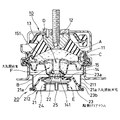
まず図1に示す第一実施例の液体封入式マウントは、マウント本体10が金属製の略円筒状のマウントケース11と、その上部中央に配置された金属製ボス12とを弾性的に連結する傘状の厚肉エラストマからなる弾性体13と、マウントケース11の下側に配置された薄肉シート状のエラストマからなるダイアフラム14とを備え、マウントケース11の内周には、前記弾性体13とダイアフラム14との間の密閉空間を、弾性体13側(上側)の第一液室Aとダイアフラム14側(下側)の第二液室Bとに仕切る仕切板15が固定され、前記第一液室Aと第二液室Bは、オリフィスC及び通孔Dを介して互いに連通されている。第一液室A、第二液室B、オリフィスC及び通孔Dからなる前記密閉空間には、液体(以下、封入液という)が封入されている。
【0016】
マウントケース11は、略円筒状の上側ケース部材111と、この上側ケース部材111の内周に配置された内側ケース部材112と、下側ケース部材113が互いにかしめられ組み立てられたものであり、このうち下側ケース部材113の延長部113aが車体(図示省略)側に固定され、ボス12は、ボルト121を介してエンジン(図示省略)側に固定されるようになっている。弾性体13は、外径部及び内径部がマウントケース11のうちの内側ケース部材112及びボス12に一体化された状態に成形されている。マウントケース11における上側ケース部材111の上部には弾性体13の上方を取り囲むようにボス12の上側の位置へ延在されたストッパ部111aが形成される一方、ボス12には、弾性体13の外径部(内側ケース部材112)と前記ストッパ部111aとの間に位置する外周部にエラストマからなる緩衝体123が形成されたストッパプレート122が設けられており、これによって、振動入力時のマウントケース11とボス12の相対変位量を制限し、振動入力時の弾性体13の過大な圧縮変形及び引張変形を防止している。
【0017】
マウントケース11における各ケース部材111〜113の互いのかしめ部には、仕切板15の外周縁部と、その下側に配置されたダイアフラム14の外周縁部と、更にその下側に配置されたスプリングケース114の上部フランジが共に挟着されている。仕切板15の外周縁部の上面と密接衝合された内側ケース部材112は、その内周部112aが一旦上方へ延びて更に下側へ折り返された逆U字形の断面形状を呈しており、オリフィスCは、弾性体13の一部が回り込んで被着されたこの内側ケース部材112の内周部112aと、仕切板15の外周縁部との間を、図1におけるII−II線で切断した図2に示すように、円周方向にほぼ一周するC字状に延在されている。このオリフィスCは、円周方向一端が前記内側ケース部材112の内周部112aに形成された切欠部112bを通じて第一液室Aに開放され、他端が仕切板15に開設された小孔15aを通じて第二液室Bに開放されている。
【0018】
仕切板15の中央部には、第二液室B側(下側)へ突出した筒状部151が形成され、通孔Dはこの筒状部151によって形成されている。オリフィスCは円周方向に長くかつ狭い流路であるため、このオリフィスCを封入液が流れる際には大きな流動抵抗を発生するのに対し、前記通孔Dは、オリフィスCに比較して流路長さが十分に短くしかも流路断面が大きいため、ここを封入液が流れる時の流動抵抗は小さなものとなる。
【0019】
ダイアフラム14の中央部には、上方へ環状に突出したエラストマからなる弁部141が一体形成されており、通孔Dにおける筒状部151の下端に形成された鍔部152と接離自在に対向している。金属環141aで補強されたこの弁部141と、底部中央が開口されたスプリングケース114との間には、コイルスプリング24がその自由長よりも適宜圧縮された状態で介在されており、弁部141は、このコイルスプリング24の付勢力によって、前記鍔部152に密接されている。また、弁部141の内周には、容易に変形可能なサブダイアフラム141bが形成されている。
【0020】
上記第一実施例の液体封入式マウントによると、ダイアフラム14に形成された弁部141は、通常、コイルスプリング24の付勢力によって筒状部151の下端鍔部152に押し付けられて、通孔Dを閉塞した状態にある。このため、エンジン始動時のクランキングによる大振幅の低周波振動が入力され、マウントケース11とボス12との間で弾性体13が反復変形されるのに伴って第一液室Aが容積変化を受けると、通孔Dは閉塞されているから、封入液はオリフィスCを介して第一液室Aと第二液室Bの間を流動し、その時の流動抵抗による大きな減衰力を得て、前記クランキング振動を早期に減衰させる。
【0021】
また、車両走行中のエンジンの高速回転による高周波数域の継続的な機関振動が入力されると、この振動は振幅が小さいため、第一液室Aの液圧の反復変化は、通孔Dを通じてこの液圧変化が作用するサブダイアフラム141bの反復変位によって吸収されるため、封入液はオリフィスCを殆ど流通せず、動ばね定数が低く維持される。振動変位が入力された時にボス12とマウントケース11及び仕切板15との間で封入液を介して伝達される力は、第一液室Aが容積変化を受けることによる封入液の圧力に比例するため、サブダイアフラム141bの反復変形による第一液室Aの液圧変化の吸収によって、機関振動に対する優れた振動絶縁性を発揮する。このとき、サブダイアフラム141bの反復変位と共に封入液が通孔Dを小刻みに反復移動するため、通孔DでもオリフィスCとは異なる適当な減衰を発生する。
【0022】
また、走行中の車体のバウンドによる衝撃等、サブダイアフラム141bの反復変形による液圧吸収能力を超えるような、第一液室Aの大きな液圧変化を発生させる大振幅の振動が入力されると、通孔Dが閉塞されていることによって、先に述べたクランキング入力の場合と同様に封入液がオリフィスCを通じて第一液室1と第二液室2の間を流通し、この時の流動抵抗によって、衝撃入力に対する良好な緩衝性を得ると共に、その振動を短時間で制止する。
【0023】
この液体封入式マウントによれば、第一液室Aと第二液室Bとを画成している仕切板15が、単一の金属板のプレス成形品によって通孔D(筒状部151)と共に形成され、また、オリフィスCはこの仕切板15とマウントケース11における内側ケース部材112を互いにかしめて組み立てる際に形成され、弁部141もダイアフラム14の一部として成形される。しかも、小振幅の高周波振動を従来のような可動仕切板によらず、前記弁部141に形成したサブダイアフラム141bによって吸収するようにしたため、部品数が少なく、構造も簡素になって、安価に製作することができる。しかも、弁部141がエラストマからなるため、通孔Dの閉塞状態における密封性が良い。
【0024】
また、衝撃による大荷重の振動変位が入力された場合、その最初の半周期における弾性体13の圧縮変形に伴って第一液室Aの液圧が極端に上昇した場合は、サブダイアフラム141bに作用するこの液圧によって、図3(a)に示すように、弁部141がコイルスプリング24の付勢力に抗して筒状部151の下端鍔部152から離間し、前記第一液室Aの液圧を通孔Dを通じて第二液室Bに開放する。そして、次の半周期における弾性体13の復元動作に伴って第一液室Aが拡張されるリバウンド過程では、弁部141がコイルスプリング24の付勢力によって再び通孔Dを塞ぐが、このとき、負圧となる第一液室Aの液圧と、大気圧との圧力差によるサブダイアフラム141bの通孔D側への変位が、図3(b)に示すように、筒状部151の下端鍔部152との当接によって規制される。このため、前記大荷重の振動変位入力時におけるサブダイアフラム141bの過大変形による破損が防止される。
【0025】
なお、発明者が行った実験によると、車体のバウンド等の衝撃入力によって上昇する第一液室Aの液圧は、通常1〜1.5気圧であることが判明している。したがって、弁部141の開弁圧が例えば1.5〜2気圧となるようにコイルスプリング24の荷重を設定しておくことによって、通常の衝撃入力では弁部141が開放動作されることなく、オリフィスCによる良好な減衰が発揮される。
【0026】
図4は、本発明に係る液体封入式マウントの第二実施例を示すものである。この実施例による液体封入式マウントは、マウント本体10の下側に、弁部141を開閉させるための負圧アクチュエータ20を一体に設けることによって、後述のように、アイドル振動に対する吸収機能を付加したものである。また、高周波・小振幅の継続的な機関振動に対する振動伝達率低減効果を高める目的で、上記第二実施例における弁部141の内周に、第一実施例と同様のサブダイアフラム141bが形成されたものである。
【0027】
負圧アクチュエータ20は、略円筒状の上側部材211と、その内周下部に配置された内側部材212と、前記上側部材211の下側に配置されたカップ状の下側部材213が互いにかしめられ組み立てられたアクチュエータケース21を有し、このアクチュエータケース21内に移動自在に配置され弁部141を一体に設けたリテーナ22と、外周縁部及び内周部が前記内側部材212及びリテーナ22に一体化された状態に成形された駆動ダイアフラム23と、前記リテーナ22と下側部材213との間に適宜圧縮状態に介在されたコイルスプリング24とを有する。アクチュエータケース21の上側部材211の上部フランジは、マウントケース11のかしめ部に、仕切板15の外周縁部及びダイアフラム14の外周縁部と共に一体にかしめられており、下側部材213には図示されていない負圧発生源(例えばエンジンのピストンによる吸気圧又はポンプが利用される)から前記駆動ダイアフラム23と下側部材213との間の負圧室Eに負圧を導入するためのノズル25が開設されている。また、前記ダイアフラム14と、負圧アクチュエータ20における駆動ダイアフラム23は、前記弁部141と共に、エラストマによって互いに連続して形成されており、前記駆動ダイアフラム23に一体的に埋設されたリテーナ22の内周部22aが弁部141の外周部内へ延在されている。
【0028】
すなわち、負圧アクチュエータ20は、負圧室Eに負圧を印加することによって、リテーナ22がコイルスプリング24を圧縮しながら駆動ダイアフラム23と共に前記負圧室Eを縮小させるように下側へ変位し、前記負圧を解除すると、コイルスプリング24の付勢力によってリテーナ22が上方へ変位するものである。マウント本体10のダイアフラム14に形成された弁部141は、負圧アクチュエータ20におけるリテーナ22に一体に設けられているため、このリテーナ22と一体に上下に変位し、筒状部151の下端外周縁152と接離して、通孔Dを開閉する。
【0029】
次に、この第二実施例による液体封入式マウントの作動について説明すると、負圧アクチュエータ20の負圧室Eに負圧を導入していない通常の状態では、先の第一実施例と同様、弁部141はコイルスプリング24の付勢力によって下端外周縁152と密接し通孔Dが閉塞されている。したがって、この状態でエンジン始動時のクランキングによる大振幅の低周波振動が入力され、マウントケース11とボス12との間で弾性体13が反復変形されるのに伴って第一液室Aが容積変化を受けると、先に述べたように、封入液はオリフィスCを介して第一液室Aと第二液室Bの間を流動し、その時の流動抵抗による大きな減衰力を得て、前記クランキング振動を早期に減衰させる。
【0030】
また、エンジンのアイドリング時には、負圧アクチュエータ20の負圧室Eに負圧を印加することによって、弁部141を筒状部151の下端外周縁152から下方へ離間させ、通孔Dを開放する。この状態でアイドル振動が入力されると、両液室A,B間での封入液の移動が通孔Dを介して短絡され、流動抵抗が少なくなるので、第一液室Aの液圧変化が有効に吸収され、動ばね定数が低下するため、アイドル振動に対して優れた振動絶縁性を発揮する。
【0031】
また、車両走行中は負圧室Eの負圧を解除することによって、弁部141を再び筒状部151の下端外周縁152に密接させ、通孔Dを閉塞する。そしてこの状態でエンジンの高速回転による高周波数域の継続的な機関振動が入力されると、この振動は振幅が極めて小さいため、第一液室Aの液圧の反復変化が、通孔Dを通じてこの液圧変化が作用するサブダイアフラム141bの反復変位によって吸収される。したがって、通孔Dが閉塞されているにも拘らず、封入液はオリフィスCを殆ど流通せず、動ばね定数が低く維持されて、優れた振動絶縁性を発揮する。また、この走行中の車体のバウンドによる衝撃等、弾性体13の拡張弾性変形による液圧吸収能力を超えるような、第一液室Aの大きな液圧変化を発生させる大振幅の振動が入力されると、通孔Dが閉塞されていることによって、先に述べたクランキング入力の場合と同様に封入液がオリフィスCを通じて第一液室1と第二液室2の間を流通し、この時の流動抵抗によって、衝撃入力に対する良好な緩衝性を得ると共に、その振動を短時間で制止する。
【0033】
この第二実施例によれば、マウント本体10におけるダイアフラム14と、負圧アクチュエータ20における駆動ダイアフラム23が、弁部141を介して一体的に形成されているので、部品数や工程数が削減される。
【0034】
図4に示す上述の第二実施例の液体封入式マウントにおいて、ダイアフラム14と駆動ダイアフラム23の間は大気開放室Fとなっており、これによって負圧アクチュエータ20の負圧室Eに対する負圧の印加あるいは解除による駆動ダイアフラム23の円滑な動作を許容すると共に、第二液室Bと負圧室Eの間での圧力伝播を絶縁している。ところが、図4に示す駆動ダイアフラム23の屈曲形状によれば、車両走行中などに、アクチュエータケース21における上側部材211に開設された大気開放用窓(図示省略)から大気開放室Fに侵入した泥水や砂等が、駆動ダイアフラム23の谷部空間23Sに溜り、この駆動ダイアフラム23の耐久性を著しく低下させる恐れがある。
【0035】
そこで本発明に係る液体封入式マウントの第三実施例は、図5に示すように、負圧アクチュエータ20の駆動ダイアフラム23を、リテーナ22と一体の内周部23aが、アクチュエータケース21に定着された外周部23bに対して相対的に高位置となる略テーパ状とし、アクチュエータケース21の上側部材211に開設した大気開放用窓21aの下端縁を、前記外周部23bの上面位置と略一致させたものである。この構成によれば、大気開放用窓21aから大気開放室Fに泥水や砂等がいったん侵入しても、このような異物は駆動ダイアフラム23による斜面上を流れ落ちて、大気開放用窓21aから外部へ容易に排出されるため、駆動ダイアフラム23上へ溜ることはない。
【0036】
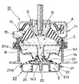
図6は本発明に係る液体封入式マウントの第四実施例を示す断面図、図7はその負圧アクチュエータ部分を分離して示す正面図である。この液体封入式マウントは、アクチュエータケース21における上側部材211が、マウントケース11にかしめられた環状の上部フランジ211aと、アクチュエータケース21における下側部材213にかしめられた環状の下部フランジ211bと、この上部フランジ211aと下部フランジ211bを円周方向180°対象位置で橋絡する一対の橋絡部211cとからなり、マウント本体10におけるダイアフラム14及び負圧アクチュエータ20における駆動ダイアフラム23のそれぞれの外周縁が、前記上部フランジ211a及び下部フランジ211bに一体に加硫接着されている。前記ダイアフラム14と駆動ダイアフラム23は、図5に示す第三実施例と同様、弁部141と共にエラストマによって互いに連続して形成されている。
【0037】
弁部141に埋設されたリテーナ22の下面中央、すなわち弁部141と反対側の部分には、エラストマによる厚肉部143が突出形成されている。この厚肉部143は、負圧室E内への負圧の導入によって駆動ダイアフラム23及び弁部141を所定量だけ下方変位した時点で負圧導入ノズル25を閉塞するので、開弁状態において駆動ダイアフラム23に過大な差圧が作用するのを有効に防止すると共に、緩衝体としての機能を有する。
【0038】
アクチュエータケース21の上側部材211は、橋絡部211cの円周方向両側に位置する一対の窓部211d,211eを有し、この窓部211d,211eの存在によって、ダイアフラム14及び駆動ダイアフラム23の外周縁を成形と同時に前記上側部材211に焼き付ける(加硫接着する)ことが可能となっている。すなわち、ダイアフラム14、弁部141及び駆動ダイアフラム23からなる連続した成形体を、上側部材211と一体に加硫成形するに際しては、図8に示すように、ダイアフラム14の上面及び弁部141を成形する上型31と、駆動ダイアフラム23の下面を成形する下型32と、ダイアフラム14の下面及び駆動ダイアフラム23の上面を成形する円周方向二分割された中間型33とを備える金型30が用いられる。そして、下型32上に予め上側部材211及びリテーナ22をセットし、前記中間型33(33a,33b)を、上側部材211内にその窓部211d,211eから進入させて互いの分割面を衝合させ、上型31及び下型32と共に型締めすることによって、外周縁が上側部材211の上部フランジ211a及び下部フランジ211bに臨んで連続したキャビティ34が形成されるのである。
【0039】
したがって、この第五実施例の液体封入式マウントによれば、マウント本体10におけるダイアフラム14と、負圧アクチュエータ20における駆動ダイアフラム23が、弁部141を介して一体的に形成されていることによるコスト低減効果ばかりでなく、アクチュエータケース21に、第二及び第三実施例の場合のような内側部材212が不要となるので、更なる構造の簡素化によって低価格化が実現される。また、ダイアフラム14の外周縁がアクチュエータケース21の上側部材211の上部フランジ211aに加硫接着されているため、マウントケース11や仕切板15とのかしめ作業が容易になり、駆動ダイアフラム23の外周縁がアクチュエータケース21に加硫接着されているため、負圧アクチュエータ20における負圧室Eのシール性も向上し、その作動の信頼性が一層高められる。
【0040】
なお、図5の第三実施例あるいは図6の第四実施例においても、第一あるいは第二実施例と同様、弁部141の内周に、通孔Dの内周空間に臨むサブダイアフラム141bを形成して、高周波数域の継続的な機関振動に対する振動絶縁性の向上を図ることができる。
【0041】
【発明の効果】
本発明の液体封入式マウントによれば、従来のように電磁弁によって封入液の流路を切り換えたり、仕切板の内部に設けた可動仕切板によって高周波小振幅振動を吸収するものに比較して、構造が簡素化されるので、優れた防振性能を安価な製造コストで実現可能であると共に、耐久性を向上することができる。
【図面の簡単な説明】
【図1】 本発明に係る液体封入式マウントの第一実施例を示す断面図である。
【図2】 図1におけるII−II線で切断した断面図である。
【図3】 上記第一実施例における作動説明図である。
【図4】 本発明に係る液体封入式マウントの第二実施例を示す断面図である。
【図5】 本発明に係る液体封入式マウントの第三実施例を示す断面図である。
【図6】 本発明に係る液体封入式マウントの第四実施例を示す断面図である。
【図7】 上記第四実施例における負圧アクチュエータ部分をマウント本体から分離して示す正面図である。
【図8】 上記第四実施例におけるダイアフラム、弁部及び駆動ダイアフラムからなる連続した成形体の加硫成形工程を示す説明図である。
【符号の説明】
10 マウント本体
11 マウントケース
111 上側ケース部材
111a ストッパ部
112 内側ケース部材
112a 内周部
112b 切欠部
113 下側ケース部材
14 スプリングケース
12 ボス
121 ボルト
122 ストッパプレート
123 緩衝体
13 弾性体
14 ダイアフラム
141 弁部
141b サブダイアフラム
143 厚肉部
15 仕切板
15a 小孔
151 筒状部
152 下端鍔部
20 負圧アクチュエータ(流体圧アクチュエータ)
21 アクチュエータケース
21a 大気開放用窓
211 上側部材
211a 上部フランジ
211b 下部フランジ
211c 橋絡部
211d,211e 窓部
212 内側部材
213 下側部材
22 リテーナ
23 駆動ダイアフラム
23a 内周部
23b 外周部
24 コイルスプリング
25 ノズル
30 金型
31 上型
32 下型
33 中間型
34 キャビティ
A 第一液室
B 第二液室
C オリフィス
D 通孔
E 負圧室
F 大気開放室[0001]
BACKGROUND OF THE INVENTION
The present invention relates to a liquid-filled mount that is used, for example, as an engine mount of an automobile and uses the flow resistance of liquid in an orifice for vibration damping.
[0002]
[Prior art]
The anti-vibration mount for an automobile engine is not only insulated against continuous engine vibration transmission during idling or running, but also due to low-frequency, large-amplitude vibration when starting the engine and bouncing of the vehicle body during running. There is a demand for excellent damping properties for quickly damaging impact vibration. In order to realize such a function, there is typically a liquid sealed mount (liquid sealed vibration isolator) disclosed in Japanese Patent Application Laid-Open No. 59-117930.
[0003]
In this liquid-sealed mount, the restriction between the first fluid chamber and the second fluid chamber, which undergoes a volume change due to deformation of the elastic body due to vibration input, is large and the flow resistance is small. It communicates through a through hole, and the through hole can be opened and closed by a solenoid valve structure.
[0004]
In other words, when the engine is started, the through hole is closed with a solenoid valve so that the filled liquid flows between the two fluid chambers through the orifice, so that a large amplitude vibration due to cranking of the engine is quickly attenuated by the flow resistance. be able to. Further, by opening the through hole during idle operation, the movement of the sealed liquid between the fluid chambers is short-circuited and the dynamic spring constant is reduced, so that the transmission of idle vibration can be effectively absorbed and insulated. . Further, by closing the through-hole again while the vehicle is running, the change in hydraulic pressure in the first fluid chamber caused by the continuous input of high-frequency vibration with a small amplitude due to the high-speed rotation of the engine is reduced between the second fluid chamber and the second fluid chamber. Is absorbed by the vibrational motion of the movable partition plate interposed therebetween, and the dynamic spring constant is reduced, so that the transmission of the high-frequency small-amplitude vibration can be effectively absorbed and insulated, and the large-amplitude due to the shake during running etc. When vibration is input, the movable range of the movable partition plate is limited, so that the filled liquid flows between the fluid chambers through the orifice, and the shock resistance during traveling is quickly stopped by the flow resistance. be able to.
[0005]
[Problems to be solved by the invention]
In the conventional liquid-filled mount, a movable partition plate and a disk member for housing the movable partition plate are required, so that the number of parts increases and the shape thereof must be complicated. In addition, the valve part that opens and closes the through-hole forms a cylindrical surface that slides in the axial direction with the inner peripheral surface of this through-hole, and in order to perform its operation smoothly, the sliding part must be machined with high precision. I must. Therefore, there is a problem that the manufacturing cost becomes high.
[0006]
The present invention has been made under the circumstances as described above, and its technical problem is that it has excellent vibration insulation against continuous engine vibration input and excellent control against large amplitude vibration input. The object of the present invention is to provide a liquid-filled mount with vibration properties at low cost.
[0007]
[Means for Solving the Problems]
As a means for effectively solving the technical problem described above, the liquid-sealed mount according to the present invention has a flow resistance on a partition plate that partitions the first liquid chamber on the elastic body side and the second liquid chamber on the diaphragm side. And a through hole having a flow resistance smaller than that of the orifice is formed by communicating the two liquid chambers with each other, and a coil spring is formed on the diaphragm at the outer peripheral edge of the second liquid chamber side of the through hole. The valve that is in close contact by the biasing force is integratedA sub-diaphragm is formed on the inner periphery of the valve portion, which faces the inner peripheral space of the through hole and is repeatedly deformed by a change in the hydraulic pressure of the first liquid chamber acting through the through hole. It is. In this configuration, more preferably, a fluid pressure actuator that opens and closes the valve portion with a drive diaphragm that operates against the urging force of the coil spring by applying fluid pressure is attached to the mount case. Further, as other means, an orifice for generating a flow resistance in a partition plate that partitions between the first liquid chamber on the elastic body side and the second liquid chamber on the diaphragm side, and a through-hole having a smaller flow resistance than the orifice are described above. Both the liquid chambers are formed in communication with each other, and a valve portion that is in close contact with the outer peripheral edge of the through hole on the second liquid chamber side of the through hole by a biasing force of a coil spring is formed integrally with the mount case. In addition, in the liquid-filled mount to which the fluid pressure actuator that opens and closes the valve portion with a drive diaphragm that operates against the urging force of the coil spring by applying fluid pressure, the drive diaphragm is connected to the mount case. The diaphragm and the drive diaphragm are substantially tapered so that the inner periphery is higher than the outer periphery fixed to the integral actuator case. Facing the atmosphere opening chamber of the lower edge of the air opening window which is opened in said actuator case the height is the upper surface substantially matching the outer peripheral portion between. Alternatively, the outer peripheral edges of each of the diaphragm and the drive diaphragm are vulcanized and bonded to an actuator case integrated with the mount case.
[0008]
DETAILED DESCRIPTION OF THE INVENTION
In a preferred embodiment of the present invention, a sub-diaphragm is formed on the inner periphery of the valve portion so as to face the inner peripheral space of the through hole. That is, when high-frequency small-amplitude vibration is input in the closed state of the through-hole by the valve portion, the change in the hydraulic pressure in the first liquid chamber corresponding to the vibration displacement is absorbed by repeated deformation of the sub-diaphragm. It is.
[0009]
In addition, by providing the mount case with a fluid pressure actuator that incorporates a drive diaphragm that operates against the biasing force of the coil spring by applying a fluid pressure to the valve portion that opens and closes the through hole, the valve portion Can be opened and closed.
[0010]
That is, in this case, the valve portion formed in the diaphragm is normally in a state in which the through hole is closed by the urging force of the coil spring. Demonstrates vibration damping force due to flow resistance when circulating. For idle vibration input, the fluid pressure actuator forcibly separates the valve portion from the outer peripheral edge of the through hole against the biasing force of the coil spring, that is, by opening the through hole. In addition, it exhibits a vibration insulation effect due to a decrease in the dynamic spring constant. When the vehicle is driven at a high speed, the through hole is closed again, and the change in the hydraulic pressure in the first fluid chamber is applied to the expansion elasticity of the elastic body or the valve section in response to the input of high-frequency small-amplitude vibration due to engine vibration. Absorbed by repetitive deformation of the formed sub-diaphragm and exerts vibration insulation action due to a decrease in the dynamic spring constant. Similarly, the sealing liquid flows through the orifice by increasing the deformation amount of the elastic body to obtain a vibration damping force.
[0011]
When a sub-diaphragm for absorbing high-frequency small-amplitude vibration is formed in the valve portion, this sub-diaphragm is not connected to the first through the through-hole when a large load is input due to, for example, the above-described running shake. There is a concern that the liquid chamber may be damaged by receiving excessive liquid pressure from the liquid chamber. However, the force that presses the valve portion against the outer peripheral edge of the end on the second liquid chamber side of the through hole depends on the biasing force of the coil spring, so that the biasing force of the coil spring is appropriately set. If set, when the fluid pressure in the first fluid chamber exceeds a predetermined value, the valve portion opens the through hole against the biasing force of the coil spring, so that the sub-diaphragm can be prevented from being damaged. it can.
[0012]
Further, as described above, since the valve portion that opens and closes the through hole is operated by the drive diaphragm of this fluid pressure actuator, the drive diaphragm of this actuator is also formed integrally with the diaphragm of the mount together with the valve portion, so that the structure can be obtained. It can be simplified.
[0013]
In this case, the drive diaphragm of the fluid pressure actuator has a substantially tapered shape in which the inner peripheral portion is positioned higher than the outer peripheral portion fixed to the actuator case integrated with the mount case, and is provided in the atmosphere opening chamber between the diaphragm and the drive diaphragm. The height of the lower edge of the air opening window opened in the actuator case is substantially matched with the upper surface of the outer peripheral portion, thereby driving muddy water and sand that has entered the air opening chamber from the air opening window. Without being accumulated on the upper surface of the diaphragm, it is easily discharged to the outside. Further, the structure can be further simplified by integrally vulcanizing and bonding the outer peripheral edges of the diaphragm and the driving diaphragm integrated therewith to the actuator case connected to the mount case.
[0014]
【Example】
Several specific embodiments of the liquid filled mount according to the present invention will be described below together with the operation thereof with reference to the drawings.
[0015]
First, in the liquid-filled mount of the first embodiment shown in FIG. 1, the
[0016]
The
[0017]
The caulking portions of the
[0018]
A
[0019]
A
[0020]
According to the liquid-filled mount of the first embodiment, the
[0021]
In addition, when continuous engine vibration in a high frequency range due to high-speed rotation of the engine while the vehicle is running is input, since this vibration has a small amplitude, the repeated change in the fluid pressure in the first fluid chamber A is caused by the through hole D. The fluid is absorbed by repeated displacement of the sub-diaphragm 141b on which the hydraulic pressure changes, so that the sealed liquid hardly circulates through the orifice C and the dynamic spring constant is kept low. The force transmitted through the sealing liquid between the
[0022]
In addition, when a large-amplitude vibration that causes a large fluid pressure change in the first fluid chamber A, such as an impact caused by a bouncing of a running vehicle body, exceeds the fluid pressure absorption capability due to repeated deformation of the sub-diaphragm 141b, is input. As the through hole D is closed, the sealed liquid flows between the first liquid chamber 1 and the second liquid chamber 2 through the orifice C as in the case of the cranking input described above. The flow resistance provides a good shock-absorbing property against impact input and suppresses the vibration in a short time.
[0023]
According to this liquid-sealed mount, the
[0024]
In addition, when a vibration displacement of a large load due to an impact is input, if the hydraulic pressure in the first liquid chamber A is extremely increased due to the compression deformation of the
[0025]
According to an experiment conducted by the inventors, it has been found that the fluid pressure in the first fluid chamber A that rises due to an impact input such as a bouncing of the vehicle body is usually 1 to 1.5 atmospheres. Therefore, by setting the load of the
[0026]
FIG. 4 shows a second embodiment of the liquid-filled mount according to the present invention. In the liquid-sealed mount according to this embodiment, a
[0027]
In the
[0028]
That is, when the
[0029]
Next, the operation of the liquid-sealed mount according to the second embodiment will be described. In a normal state where no negative pressure is introduced into the negative pressure chamber E of the
[0030]
Further, when the engine is idling, by applying a negative pressure to the negative pressure chamber E of the
[0031]
Further, by releasing the negative pressure in the negative pressure chamber E during traveling of the vehicle, the
[0033]
thisSecond embodimentAccording to the above, the
[0034]
The second embodiment shown in FIG.In the liquid-sealed mount, the air opening chamber F is provided between the
[0035]
Therefore, the liquid-filled mount according to the present inventionThird embodimentIsFIG.As shown, the driving
[0036]
FIG.Is a liquid-filled mount according to the present invention.Fourth embodimentA cross-sectional view showingFIG.FIG. 3 is a front view showing the negative pressure actuator portion separately. The liquid-filled mount includes an annular
[0037]
A thick-
[0038]
The
[0039]
Therefore, according to the liquid-filled mount of the fifth embodiment, the cost due to the
[0040]
In addition,Third embodiment of FIG.OrThe fourth embodiment of FIG.In the first orSecond embodimentSimilarly to the above, the sub-diaphragm 141b facing the inner peripheral space of the through hole D can be formed on the inner periphery of the
[0041]
【The invention's effect】
According to the liquid-filled mount of the present invention, the flow path of the filled liquid is switched by a solenoid valve as in the prior art, or compared with a structure that absorbs high-frequency small-amplitude vibration by a movable partition plate provided inside the partition plate. Since the structure is simplified, excellent vibration isolation performance can be realized at a low manufacturing cost, and durability can be improved.
[Brief description of the drawings]
FIG. 1 is a cross-sectional view showing a first embodiment of a liquid-filled mount according to the present invention.
FIG. 2 is a cross-sectional view taken along line II-II in FIG.
FIG. 3 is an operation explanatory diagram in the first embodiment.
FIG. 4 is a cross-sectional view showing a second embodiment of the liquid filled mount according to the present invention.
FIG. 5 is a cross-sectional view showing a third embodiment of the liquid filled mount according to the present invention.
FIG. 6 is a cross-sectional view showing a fourth embodiment of the liquid filled mount according to the present invention.
[Fig. 7]It is a front view which isolate | separates and shows the negative pressure actuator part in the said 4th Example from the mount main body.
[Fig. 8]It is explanatory drawing which shows the vulcanization molding process of the continuous molded object which consists of a diaphragm in the said 4th Example, a valve part, and a drive diaphragm.
[Explanation of symbols]
10 Mount body
11 Mount case
111 Upper case member
111a Stopper part
112 Inner case member
112a Inner circumference
112b Notch
113 Lower case member
14 Spring case
12 Boss
121 volts
122 Stopper plate
123 Buffer
13 Elastic body
14 Diaphragm
141 Valve
141b Sub diaphragm
143 Thick part
15 Partition plate
15a small hole
151 cylindrical part
152 Bottom buttock
20 Negative pressure actuator (fluid pressure actuator)
21 Actuator case
21aOpen window
211 Upper member
211a Upper flange
211b Lower flange
211c bridge
211d, 211e Window
212 Inner member
213 Lower member
22 Retainer
23 Drive diaphragm
23a Inner circumference
23b Outer periphery
24 Coil spring
25 nozzles
30 mold
31 Upper mold
32 Lower mold
33 Intermediate type
34 cavities
A First liquid chamber
B Second liquid chamber
C Orifice
D through hole
E Negative pressure chamber
F Air release room
Claims (4)
前記マウントケース(11)に前記弾性体(13)と反対側で一体的に設けられたシート状のエラストマからなるダイアフラム(14)と、
前記マウントケース(11)の内周に設けられて前記弾性体(13)側の第一液室(A)と前記ダイアフラム(14)側の第二液室(B)との間を仕切る仕切板(15)と、
を備え、
前記仕切板(15)には流動抵抗を発生するオリフィス(C)及びこのオリフィス(C)よりも流動抵抗の小さい通孔(D)が前記両液室(A,B)を互いに連通して形成され、
前記ダイアフラム(14)には前記通孔(D)の第二液室(B)側の端部外周縁(152)にコイルスプリング(24)の付勢力により密接される弁部(141)が一体に形成され、
前記弁部(141)の内周に、前記通孔(D)の内周空間に臨んで、この通孔(D)を介して作用する第一液室(A)の液圧変化によって反復変形されるサブダイアフラム(141b)が形成されたことを特徴とする液体封入式マウント。An elastic body (13) made of an elastomer provided integrally between the mount case (11) and the boss (12) and continuous in the circumferential direction;
A diaphragm (14) made of a sheet-like elastomer provided integrally with the mount case (11) on the opposite side to the elastic body (13);
A partition plate provided on the inner periphery of the mount case (11) for partitioning the first liquid chamber (A) on the elastic body (13) side and the second liquid chamber (B) on the diaphragm (14) side (15) and
With
In the partition plate (15), an orifice (C) for generating a flow resistance and a through hole (D) having a smaller flow resistance than the orifice (C) are formed so as to communicate the two liquid chambers (A, B) with each other. And
The diaphragm (14) is integrally provided with a valve portion (141) that is brought into close contact with the outer peripheral edge (152) of the end of the through hole (D) on the second liquid chamber (B) side by the urging force of the coil spring (24). Formed into
Repetitively deformed by the change in the hydraulic pressure of the first liquid chamber (A) acting through the through hole (D) on the inner circumference of the valve part (141), facing the inner circumferential space of the through hole (D). A liquid-sealed mount, characterized in that a sub-diaphragm (141b) is formed .
マウントケース(11)に、弁部(141)を流体圧の印加によってコイルスプリング(24)の付勢力に抗して動作する駆動ダイアフラム(23)で開閉させる流体圧アクチュエータ(20)が取り付けられたことを特徴とする液体封入式マウント。In the description of claim 1,
A fluid pressure actuator (20) is mounted on the mount case (11) to open and close the valve portion (141) with a drive diaphragm (23) that operates against the biasing force of the coil spring (24) by applying fluid pressure. This is a liquid-filled mount.
前記マウントケース(11)に前記弾性体(13)と反対側で一体的に設けられたシート状のエラストマからなるダイアフラム(14)と、
前記マウントケース(11)の内周に設けられて前記弾性体(13)側の第一液室(A)と前記ダイアフラム(14)側の第二液室(B)との間を仕切る仕切板(15)と、
を備え、
前記仕切板(15)には流動抵抗を発生するオリフィス(C)及びこのオリフィス(C)よりも流動抵抗の小さい通孔(D)が前記両液室(A,B)を互いに連通して形成され、
前記ダイアフラム(14)には前記通孔(D)の第二液室(B)側の端部外周縁(152)にコイルスプリング(24)の付勢力により密接される弁部(141)が一体に形成され、
前記マウントケース(11)に、前記弁部(141)を流体圧の印加によってコイルスプリング(24)の付勢力に抗して動作する駆動ダイアフラム(23)で開閉させる流体圧アクチュエータ(20)が取り付けられ、
前記駆動ダイアフラム(23)を、前記マウントケース(11)と一体のアクチュエータケース(21)に定着された外周部(23b)よりも内周部(23a)が高位置となる略テーパ状とし、前記ダイアフラム(14)と駆動ダイアフラム(23)の間の大気開放室(F)に臨んで前記アクチュエータケース(21)に開設した大気開放用窓(21a)の下端縁の高さを前記外周部(23b)の上面と略一致させたことを特徴とする液体封入式マウント。 An elastic body (13) made of an elastomer provided integrally between the mount case (11) and the boss (12) and continuous in the circumferential direction;
A diaphragm (14) made of a sheet-like elastomer provided integrally with the mount case (11) on the opposite side to the elastic body (13);
A partition plate provided on the inner periphery of the mount case (11) for partitioning the first liquid chamber (A) on the elastic body (13) side and the second liquid chamber (B) on the diaphragm (14) side (15) and
With
In the partition plate (15), an orifice (C) for generating a flow resistance and a through hole (D) having a smaller flow resistance than the orifice (C) are formed so as to communicate the two liquid chambers (A, B) with each other. And
The diaphragm (14) is integrally provided with a valve portion (141) that is brought into close contact with the outer peripheral edge (152) of the end of the through hole (D) on the second liquid chamber (B) side by the urging force of the coil spring (24). Formed into
A fluid pressure actuator (20) is attached to the mount case (11) to open and close the valve portion (141) by a drive diaphragm (23) that operates against the urging force of the coil spring (24) by applying fluid pressure. And
The drive diaphragm (23) has a substantially tapered shape in which an inner peripheral portion (23a) is positioned higher than an outer peripheral portion (23b) fixed to an actuator case (21) integrated with the mount case (11), The height of the lower edge of the air release window (21a) opened in the actuator case (21) facing the air release chamber (F) between the diaphragm (14) and the drive diaphragm (23) is set to the outer peripheral portion (23b). A liquid-filled mount characterized by being substantially coincident with the upper surface of
前記マウントケース(11)に前記弾性体(13)と反対側で一体的に設けられたシート状のエラストマからなるダイアフラム(14)と、
前記マウントケース(11)の内周に設けられて前記弾性体(13)側の第一液室(A)と前記ダイアフラム(14)側の第二液室(B)との間を仕切る仕切板(15)と、
を備え、
前記仕切板(15)には流動抵抗を発生するオリフィス(C)及びこのオリフィス(C)よりも流動抵抗の小さい通孔(D)が前記両液室(A,B)を互いに連通して形成され、
前記ダイアフラム(14)には前記通孔(D)の第二液室(B)側の端部外周縁(152)にコイルスプリング(24)の付勢力により密接される弁部(141)が一体に形成され、
前記マウントケース(11)に、弁部(141)を流体圧の印加によってコイルスプリング(24)の付勢力に抗して動作する駆動ダイアフラム(23)で開閉させる流体圧アクチュエータ(20)が取り付けられ、
前記ダイアフラム(14)及びこれと一体の駆動ダイアフラム(23)のそれぞれの外周縁がマウントケース(11)と一体のアクチュエータケース(21)に加硫接着されたことを特徴とする液体封入式マウント。 An elastic body (13) made of an elastomer provided integrally between the mount case (11) and the boss (12) and continuous in the circumferential direction;
A diaphragm (14) made of a sheet-like elastomer provided integrally with the mount case (11) on the opposite side to the elastic body (13);
A partition plate provided on the inner periphery of the mount case (11) for partitioning the first liquid chamber (A) on the elastic body (13) side and the second liquid chamber (B) on the diaphragm (14) side (15) and
With
In the partition plate (15), an orifice (C) for generating a flow resistance and a through hole (D) having a smaller flow resistance than the orifice (C) are formed so as to communicate the two liquid chambers (A, B) with each other. And
The diaphragm (14) is integrally provided with a valve portion (141) that is brought into close contact with the outer peripheral edge (152) of the end of the through hole (D) on the second liquid chamber (B) side by the urging force of the coil spring (24). Formed into
A fluid pressure actuator (20) is attached to the mount case (11) to open and close the valve portion (141) by a drive diaphragm (23) that operates against the urging force of the coil spring (24) by applying fluid pressure. ,
A liquid-sealed mount in which the outer peripheral edges of the diaphragm (14) and the drive diaphragm (23) integral with the diaphragm (14) are vulcanized and bonded to an actuator case (21) integral with the mount case (11) .
Priority Applications (1)
| Application Number | Priority Date | Filing Date | Title |
|---|---|---|---|
| JP29053195A JP3702909B2 (en) | 1995-02-10 | 1995-10-13 | Liquid filled mount |
Applications Claiming Priority (3)
| Application Number | Priority Date | Filing Date | Title |
|---|---|---|---|
| JP4502695 | 1995-02-10 | ||
| JP7-45026 | 1995-02-10 | ||
| JP29053195A JP3702909B2 (en) | 1995-02-10 | 1995-10-13 | Liquid filled mount |
Publications (2)
| Publication Number | Publication Date |
|---|---|
| JPH08277879A JPH08277879A (en) | 1996-10-22 |
| JP3702909B2 true JP3702909B2 (en) | 2005-10-05 |
Family
ID=26384983
Family Applications (1)
| Application Number | Title | Priority Date | Filing Date |
|---|---|---|---|
| JP29053195A Expired - Fee Related JP3702909B2 (en) | 1995-02-10 | 1995-10-13 | Liquid filled mount |
Country Status (1)
| Country | Link |
|---|---|
| JP (1) | JP3702909B2 (en) |
Cited By (1)
| Publication number | Priority date | Publication date | Assignee | Title |
|---|---|---|---|---|
| US9394964B2 (en) | 2012-10-26 | 2016-07-19 | Sumitomo Riko Company Limited | Fluid-filled vibration damping device |
Families Citing this family (7)
| Publication number | Priority date | Publication date | Assignee | Title |
|---|---|---|---|---|
| JP4666560B2 (en) * | 2001-06-22 | 2011-04-06 | 山下ゴム株式会社 | Liquid seal vibration isolator |
| ES2271257T3 (en) * | 2001-06-22 | 2007-04-16 | Yamashita Rubber Kabushiki Kaisha | DEVICE FOR THE CONTROL OF LIQUID RING VIBRATIONS. |
| JP4868564B2 (en) * | 2001-06-22 | 2012-02-01 | 山下ゴム株式会社 | Liquid seal vibration isolator |
| FR2872879B1 (en) * | 2004-07-07 | 2008-05-30 | Hutchinson Sa | HYDRAULIC ANTIVIBRATORY SUPPORT WITH PNEUMATIC CONTROL |
| JP4494988B2 (en) * | 2005-01-18 | 2010-06-30 | 倉敷化工株式会社 | Liquid filled anti-vibration mount device |
| JP4723958B2 (en) * | 2005-09-07 | 2011-07-13 | 株式会社ブリヂストン | Vibration isolator |
| CN111717014B (en) * | 2020-05-22 | 2021-06-22 | 浙江零跑科技有限公司 | Hydraulic suspension structure |
-
1995
- 1995-10-13 JP JP29053195A patent/JP3702909B2/en not_active Expired - Fee Related
Cited By (1)
| Publication number | Priority date | Publication date | Assignee | Title |
|---|---|---|---|---|
| US9394964B2 (en) | 2012-10-26 | 2016-07-19 | Sumitomo Riko Company Limited | Fluid-filled vibration damping device |
Also Published As
| Publication number | Publication date |
|---|---|
| JPH08277879A (en) | 1996-10-22 |
Similar Documents
| Publication | Publication Date | Title |
|---|---|---|
| US6361031B1 (en) | Adaptive hydraulic engine mount | |
| JPH08270718A (en) | Liquid sealing type mount device | |
| JP3702909B2 (en) | Liquid filled mount | |
| EP1498637A1 (en) | Vibration control equipment | |
| JP2004003614A (en) | Vibration control equipment | |
| JP4723958B2 (en) | Vibration isolator | |
| JP3698186B2 (en) | Liquid filled mount | |
| JP3700731B2 (en) | Liquid filled mount | |
| JP2000291722A (en) | Liquid-sealed mount | |
| JPS5854247A (en) | Vibro-isolating rubber device | |
| JP2003028233A (en) | Fluid-filled vibration isolator | |
| JP2009236168A (en) | Negative pressure control type fluid-filled vibration control device | |
| JP3605391B2 (en) | Two-chamber support bearing device with hydraulic damping part | |
| JPH09222148A (en) | Liquid sealing type mount | |
| JP4018366B2 (en) | Fluid filled mount | |
| JP4173066B2 (en) | Vibration isolator | |
| JP4937207B2 (en) | Fluid filled vibration isolator | |
| JP2001012537A (en) | Fluid enclosed type vibration control device | |
| JP4792417B2 (en) | Fluid filled vibration isolator | |
| JP4173085B2 (en) | Vibration isolator | |
| JP2006083980A (en) | Liquid encapsulating mount | |
| JPH02245538A (en) | Fluid-sealing type cylindrical mounting device | |
| JPH11166577A (en) | Vibration control device | |
| JPH0925986A (en) | Liquid-in type mount | |
| JPH07238968A (en) | Damper stay device |
Legal Events
| Date | Code | Title | Description |
|---|---|---|---|
| A977 | Report on retrieval |
Effective date: 20041115 Free format text: JAPANESE INTERMEDIATE CODE: A971007 |
|
| A131 | Notification of reasons for refusal |
Free format text: JAPANESE INTERMEDIATE CODE: A131 Effective date: 20050302 |
|
| A521 | Written amendment |
Effective date: 20050421 Free format text: JAPANESE INTERMEDIATE CODE: A523 |
|
| TRDD | Decision of grant or rejection written | ||
| A01 | Written decision to grant a patent or to grant a registration (utility model) |
Free format text: JAPANESE INTERMEDIATE CODE: A01 Effective date: 20050629 |
|
| A61 | First payment of annual fees (during grant procedure) |
Free format text: JAPANESE INTERMEDIATE CODE: A61 Effective date: 20050712 |
|
| R150 | Certificate of patent (=grant) or registration of utility model |
Free format text: JAPANESE INTERMEDIATE CODE: R150 |
|
| FPAY | Renewal fee payment (prs date is renewal date of database) |
Free format text: PAYMENT UNTIL: 20080729 Year of fee payment: 3 |
|
| FPAY | Renewal fee payment (prs date is renewal date of database) |
Year of fee payment: 4 Free format text: PAYMENT UNTIL: 20090729 |
|
| LAPS | Cancellation because of no payment of annual fees |