JP3701239B2 - Internal combustion engine - Google Patents
Internal combustion engine Download PDFInfo
- Publication number
- JP3701239B2 JP3701239B2 JP2001383847A JP2001383847A JP3701239B2 JP 3701239 B2 JP3701239 B2 JP 3701239B2 JP 2001383847 A JP2001383847 A JP 2001383847A JP 2001383847 A JP2001383847 A JP 2001383847A JP 3701239 B2 JP3701239 B2 JP 3701239B2
- Authority
- JP
- Japan
- Prior art keywords
- cylinder
- combustion engine
- head
- internal combustion
- head plate
- Prior art date
- Legal status (The legal status is an assumption and is not a legal conclusion. Google has not performed a legal analysis and makes no representation as to the accuracy of the status listed.)
- Expired - Fee Related
Links
Images


Classifications
-
- F—MECHANICAL ENGINEERING; LIGHTING; HEATING; WEAPONS; BLASTING
- F02—COMBUSTION ENGINES; HOT-GAS OR COMBUSTION-PRODUCT ENGINE PLANTS
- F02F—CYLINDERS, PISTONS OR CASINGS, FOR COMBUSTION ENGINES; ARRANGEMENTS OF SEALINGS IN COMBUSTION ENGINES
- F02F1/00—Cylinders; Cylinder heads
- F02F1/24—Cylinder heads
- F02F1/42—Shape or arrangement of intake or exhaust channels in cylinder heads
- F02F1/4214—Shape or arrangement of intake or exhaust channels in cylinder heads specially adapted for four or more valves per cylinder
-
- F—MECHANICAL ENGINEERING; LIGHTING; HEATING; WEAPONS; BLASTING
- F02—COMBUSTION ENGINES; HOT-GAS OR COMBUSTION-PRODUCT ENGINE PLANTS
- F02B—INTERNAL-COMBUSTION PISTON ENGINES; COMBUSTION ENGINES IN GENERAL
- F02B2275/00—Other engines, components or details, not provided for in other groups of this subclass
- F02B2275/10—Diamond configuration of valves in cylinder heads
-
- F—MECHANICAL ENGINEERING; LIGHTING; HEATING; WEAPONS; BLASTING
- F02—COMBUSTION ENGINES; HOT-GAS OR COMBUSTION-PRODUCT ENGINE PLANTS
- F02F—CYLINDERS, PISTONS OR CASINGS, FOR COMBUSTION ENGINES; ARRANGEMENTS OF SEALINGS IN COMBUSTION ENGINES
- F02F1/00—Cylinders; Cylinder heads
- F02F1/24—Cylinder heads
- F02F2001/244—Arrangement of valve stems in cylinder heads
- F02F2001/247—Arrangement of valve stems in cylinder heads the valve stems being orientated in parallel with the cylinder axis
-
- F—MECHANICAL ENGINEERING; LIGHTING; HEATING; WEAPONS; BLASTING
- F02—COMBUSTION ENGINES; HOT-GAS OR COMBUSTION-PRODUCT ENGINE PLANTS
- F02F—CYLINDERS, PISTONS OR CASINGS, FOR COMBUSTION ENGINES; ARRANGEMENTS OF SEALINGS IN COMBUSTION ENGINES
- F02F1/00—Cylinders; Cylinder heads
- F02F1/24—Cylinder heads
- F02F2001/249—Cylinder heads with flame plate, e.g. insert in the cylinder head used as a thermal insulation between cylinder head and combustion chamber
Description
【0001】
【発明の属する技術分野】
本発明は、少なくとも1つの吸気弁、少なくとも1つの排気弁、少なくとも1つの噴射装置等から選択されたもののための少なくとも1つの開口部を備えるとともに燃焼室に面するようにシリンダヘッドとシリンダの間に配置された平坦なヘッドプレートが平坦なシリンダヘッド底面に突き合わせている内燃機関内燃機関に関する。
【0002】
【従来の技術】
米国特許公報4,774,912号より、底面ヘッドプレートによって密閉され、構造が剛性で冷却水室を備えている上側部分からなる、内燃機関のシリンダヘッドが公知であり、この底面ヘッドプレートは水室に接している。シリンダヘッドの両方の部材は、ただ一つの共通構造体になるように結合されている。底面ヘッドプレートは、構造が剛性な上側部分よりも耐熱性が高くて熱伝導性の低い金属によって形成されている。このようにして、比較的大きなシリンダ厚さを実現することができる。しかしながら底面ヘッドプレートに直接接している水室は、上側部分特有の構造と冷却液のための密閉対策とを必要とし、このことで製造コストがアップする。
【0003】
ドイツ特許公開公報DE3307115A1号より、燃焼室に対向する面が、弁、点火プラグ、または噴射ノズルのための開口部を有するヘッドプレートで覆われている、内燃機関のシリンダヘッドが公知である。このヘッドプレートによって、シリンダヘッドの燃焼室側に対する絶縁を達成しようとしている。この場合、円形のヘッドプレートは、シリンダヘッドに構成されたカラー部の中に焼きばめされる。従って、シリンダヘッド底面の別個の加工と、焼きばめ工程のための追加的な作業ステップとが必要になるという欠点があり、このことは、この場合もやはり製造コストを大幅に引き上げてしまう。しかも、シリンダヘッド底面が切欠き効果によって弱くなる。これに類似するヘッドプレートはスイス特許公報CH389990A号、ドイツ特許公報DE3523131C1号,およびドイツ特許公開公報DE3039718A1号などの明細書からも公知である。
【0004】
英国特許公開公報GB111095A1号は、平坦なシリンダヘッド底面に突き合わされる底面ヘッドプレートを備える内燃機関を開示している。弁座は底面ヘッドプレートに設けられているので、底面ヘッドプレートに対して高い加工精度が要求される。
【0005】
【発明が解決しようとする課題】
上記実状に鑑み、本発明の課題は、少なくとも1つの吸気弁または少なくとも1つの排気弁ないしはその両方のために少なくとも1つの開口部を備えるとともに燃焼室に面するようにシリンダヘッドとシリンダの間に配置された平坦なヘッドプレートが平坦なシリンダヘッド底面に突き合わせている内燃機関において、シリンダヘッドでの少ない熱損失を、できるだけ簡単なやり方で実現することである。
【0006】
【課題を解決するための手段】
上記課題は、本発明によれば、前記開口部の直径がこの開口部に対応する吸気弁や排気弁のための弁座よりも大きくなっており、かつ前記吸気弁または排気弁あるいはその両方の弁座はシリンダヘッドに、またはシリンダヘッドと堅固に結合された弁座リングに設けられており、
前記ヘッドプレート(4)が、燃焼室(3)の側に、吸気弁(8)または排気弁(9)の少なくとも1つの開口部(6,7)の周囲に面取り部(10,11)を備えており、
前記面取り部(10,11)が、この面取り部(10,11)とシリンダ軸平行線(12a)との間で規定される異なる面取り角(α)をもつ少なくとも2つの領域を備えており、その際両方の領域の間における面取り角(α)の変化が連続するように構成されることによって達成される。つまり弁座の機能は、従来式のやり方で、シリンダヘッドによって引き受けられている。したがってヘッドプレートは非常に簡単に製作することができる。ここではこの平坦なヘッドプレートは、シリンダヘッド底面の平坦な接続面に突き合わせているだけである。シリンダヘッド底面にヘッドプレートを挿入するための鍔状の凹部を設ける必要はない。したがってシリンダヘッド底面は、吸気弁や排気弁さらには必要に応じて設けられることになる、噴射装置、水通過部、シリンダヘッドネジのための開口部を除いて、平坦面に加工される。したがって、このヘッドプレートは設計的な変更や追加的な加工ステップなしに、標準型シリンダヘッドと組み合わせて使用することができる。既存の標準型シリンダヘッドにも、容易に後からこのような底面ヘッドプレートを装備することができる。しかも、突き出した弁があっても、ポケット部のないピストンを、すなわち同じく平坦な頂部をもつピストンを利用できる。このことは、点火圧が高くて熱負荷が高いときに強度の面から好都合である。
さらに、流動性の観点から好都合な幾何学形状で形成されることになる面取り部が、面取り部とシリンダ軸平行線との間で規定される異なる面取り角をもつ少なくとも2つの領域を備えているので、両方の領域の間における面取り角の変化が常に連続するように構成され、弁座リングが従来式のシリンダヘッドと同様にシリンダヘッド底面に配置される。吸気弁または排気弁のためのシリンダヘッド底面の面取りが、シリンダヘッド底面ではなくてヘッドプレートに設けられることによって、弁座リングの有効高さを低減することができ、このことは、シリンダヘッドのウォータジャケットにおける冷却液の案内に有利に作用する。
【0007】
このとき本発明による実施形態では、ヘッドプレートの直径が最大でシリンダのボア径に一致していることが提案される。この場合、ヘッドプレートは円形の輪郭を有しており、このヘッドプレートを取付ネジでシリンダヘッドに取り付けるのが好ましい。上記の別案または追加策として、ヘッドプレートをユニオンナットによってインジェクタ受持孔に取り付けるように構成してもよい。
【0008】
特に好ましい実施形態では、 前記ヘッドプレートがシリンダから完全にはみ出しており、シリンダヘッドによって、シリンダブロックに、またはシリンダブロックの中に配置されたシリンダライナーに、あるいはその両方に押し付けられることが提案される。ヘッドプレートがシリンダヘッドとシリンダブロックの間の密閉手段となっていて、シリンダハウジングまたはシリンダライナーあるいはその両方に対して密閉面が形成されていれば、別個のシリンダヘッドガスケットを省略することができる。
【0009】
このときヘッドプレートは、シリンダヘッド全体の長さまたは幅あるいはその両方を超えて延びていてもよい。シリンダヘッドは、シングルシリンダヘッドとして、またはマルチシリンダヘッドとして製作されてもよい。ヘッドプレートがシリンダハウジングとシリンダヘッドの間に少なくとも1つの水通過開口部を備えていると、特に好都合である。それにより、シリンダハウジングとシリンダヘッドにはさまれた水通過部の領域でも、別個の密閉手段が必要なくなる。ヘッドプレートは、シリンダヘッドネジのための貫通孔も備えているのが好ましく、このシリンダヘッドネジによってヘッドプレートは、シリンダヘッドによってシリンダハウジングまたはシリンダライナーに押し付けられる。
【0011】
シリンダヘッド底面における熱損失を効果的に減らすために、ヘッドプレートが高耐熱性合金またはセラミックでできていると格別に有利である。あるいはヘッドプレートをオーステナイト系ステンレス鋼またはマルテンサイト系ステンレス鋼、もしくは鋳鋼で施工することも考えられる。
【0012】
【発明の実施の形態】
次に、図面を参照しながら本発明について詳しく説明する。
【0013】
機能が同じ構成部品には、どの実施例でも同じ符号が付されている。
【0014】
シリンダヘッド1とシリンダ2の間には、燃焼室3に接するヘッドプレート4が配置されている。平坦なヘッドプレート4は、吸気弁8および/または排気弁9および/または噴射装置15のための開口部を除いて閉じられた平坦なシリンダヘッド底面1aに密着して当接している。シリンダ2は各実施例では、詳しくは図示しないシリンダハウジングの中に配置されたシリンダライナー5によって構成されている。金属材料でできた平坦なヘッドプレート4は、吸気弁8ないし排気弁9のそれぞれのために開口部6,7を備えている。ガス交換のために好都合な流動ジオメトリーを構成するために、開口部6,7の回りにはそれぞれ面取り部10,11がヘッドプレート4に設けられており、これらの面取り部は、円周方向でそれぞれシリンダ軸平行線12aに対して連続的に変化する面取り角αを備えている。さらにヘッドプレート4はシリンダ軸12の領域に、噴射装置15から燃焼室3への出口14のための開口部13を備えている。どの実施例においても、弁座リング16,17によって構成されている吸気弁8ないし排気弁9のための弁座は、シリンダヘッド1に配置されている。
【0015】
図1から図6に示す実施例ではヘッドプレート4は円形に構成されており、最大でシリンダ2の穴直径Bに相当する直径Dを備えている。ヘッドプレート4は、ネジ25によって平坦なシリンダヘッド底面1aに取り付けられている。シリンダヘッド1とシリンダライナー5の間には、燃焼室3に対するシリンダヘッド1とシリンダライナー5の間の密閉機能を引き受けるシリンダヘッドガスケット18が配置されている。図5と図6からわかるように、ヘッドプレート4はシリンダ軸12の方向に、シリンダヘッドガスケット18の厚さ20よりも大きい、または小さい厚さ19を備えている。
【0016】
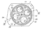
図7から図12は、シリンダ1のシリンダヘッド底面1aと、1つまたは複数のシリンダライナー5との間に配置されたヘッドプレート4が、シリンダ2のボア径Bを超えて延びており、好ましくはシリンダヘッド底面1a全体にわたって延びている第2実施例を示している。この実施例では、ヘッドプレート4がシリンダライナー5に対する封止機能を引き受けていれば、別個のシリンダヘッドガスケットを省略することができる。燃焼室3に対するシリンダライナー5とヘッドプレート4の間の密閉性を確保するために、シリンダライナー5やヘッドプレート4の封止面の領域における密閉機能をいっそう向上させるための全周にわたるそれぞれにウェブ21とこれに対応する溝22を構成すると好都合である。冷却液や潤滑剤を密閉するために、ヘッドプレート4は、弾性的なシール部材を備える積層部または装着部を有していてよい。
【0017】
第2実施例では、ヘッドプレート4は吸気弁8および排気弁9のための開口部6および7、ならびに噴射装置15の出口14のための開口部13に加えて、さらにシリンダヘッドネジのための穴23、ならびに少なくとも1つのプッシュロッド開口部24、水通過開口部28、および/またはシリンダハウジングとシリンダヘッド1の間のオイル通過穴29を備えている。符号27は、図7においてガス交換通路を示している。
【0018】
図13は、ヘッドプレート4が(ネジ25の追加または代替として)ユニオンナット25aによって噴射装置15の周囲でインジェクタ受持孔15aに取り付けられた、さらに別の実施例を示している。符号30は、シリンダ2の中で往復運動するピストンを示している。
【0019】
好ましくは耐熱性合金からなるヘッドプレート4は、シリンダヘッド底面1aにおける熱損失を減らし、それによって熱応力を少なくする。それにより、シリンダヘッド1の材料を選択するときにいっそう高い自由性が生まれる。しかもシリンダ底面の面取り部は、シリンダヘッドの構造を弱めることがない。
【0020】
尚、特許請求の範囲の項に図面との対照を便利にするために符号を記すが、該記入により本発明は添付図面の構造に限定されるものではない。
【図面の簡単な説明】
【図1】第1実施例における本発明の内燃機関を示す、シリンダを断面図で示した斜視図
【図2】図1のII−II線に沿ったシリンダヘッドの燃焼室側の断面図
【図3】図2のIII−III線に沿った内燃機関の断面図
【図4】図3の詳細部分IVを示す拡大図
【図5】図3の詳細部分Vを示す拡大図
【図6】図3の詳細部分VIを示す拡大図
【図7】第2実施例における本発明の内燃機関を示す、シリンダを断面図で示した斜視図
【図8】図7のVIII−VIII線に沿ったシリンダヘッドの燃焼室側の断面図
【図9】図8のIX−IX線に沿った内燃機関の断面図
【図10】図9の詳細部分Xを示す拡大図
【図11】図9の詳細部分XIを示す拡大図
【図12】図9の詳細部分XIIを示す拡大図
【図13】本発明の内燃機関のさらに別の実施例を示す、図3と同様の断面図
【符号の説明】
1 シリンダヘッド
1a シリンダヘッド底面
2 シリンダ
3 燃焼室
4 ヘッドプレート
6,7 開口部
8 吸気弁
9 排気弁
10,11 面取り部
16,17 弁座リング[0001]
BACKGROUND OF THE INVENTION
The present invention comprises at least one opening for one selected from at least one intake valve, at least one exhaust valve, at least one injector, etc. and between the cylinder head and the cylinder so as to face the combustion chamber. The present invention relates to an internal combustion engine in which a flat head plate disposed on the bottom face a flat bottom surface of a cylinder head.
[0002]
[Prior art]
From US Pat. No. 4,774,912, a cylinder head of an internal combustion engine is known which is sealed by a bottom head plate and consists of an upper part which is rigid in structure and has a cooling water chamber. It touches the room. Both members of the cylinder head are joined to form a single common structure. The bottom head plate is made of a metal having higher heat resistance and lower thermal conductivity than the upper portion having a rigid structure. In this way, a relatively large cylinder thickness can be realized. However, the water chamber that is in direct contact with the bottom head plate requires a structure peculiar to the upper portion and a sealing measure for the coolant, which increases the manufacturing cost.
[0003]
From German Patent Publication DE 3307115 A1, a cylinder head of an internal combustion engine is known in which the face facing the combustion chamber is covered with a head plate having an opening for a valve, a spark plug or an injection nozzle. This head plate is intended to achieve insulation from the combustion chamber side of the cylinder head. In this case, the circular head plate is shrink-fitted into the collar portion formed in the cylinder head. Therefore, there is a disadvantage that a separate machining of the bottom surface of the cylinder head and an additional work step for the shrink-fitting process are required, which again increases the production costs. In addition, the bottom surface of the cylinder head is weakened by the notch effect. Similar head plates are also known from specifications such as Swiss Patent Publication CH389990A, German Patent Publication DE3523131C1, and German Patent Publication DE3039718A1.
[0004]
GB 1111095A1 discloses an internal combustion engine with a bottom head plate that is abutted against a flat cylinder head bottom. Since the valve seat is provided on the bottom head plate, high processing accuracy is required for the bottom head plate.
[0005]
[Problems to be solved by the invention]
In view of the above, the object of the present invention is to provide at least one opening for at least one intake valve and / or at least one exhaust valve or both between the cylinder head and the cylinder so as to face the combustion chamber. In an internal combustion engine in which the arranged flat head plate is abutted against the flat bottom surface of the cylinder head, the low heat loss in the cylinder head is achieved in the simplest possible manner.
[0006]
[Means for Solving the Problems]
According to the present invention, the above-mentioned problem is that the diameter of the opening is larger than the valve seat for the intake valve and the exhaust valve corresponding to the opening, and the intake valve and / or the exhaust valve are both. The valve seat is provided on the cylinder head or on the valve seat ring firmly connected to the cylinder head ,
The head plate (4) has a chamfered portion (10, 11) around at least one opening (6, 7) of the intake valve (8) or the exhaust valve (9) on the combustion chamber (3) side. With
The chamfered portion (10, 11) includes at least two regions having different chamfer angles (α) defined between the chamfered portion (10, 11) and the cylinder axis parallel line (12a); In this case, the change of the chamfer angle (α) between both regions is achieved by being configured to be continuous . In other words, the function of the valve seat is assumed by the cylinder head in a conventional manner. Therefore, the head plate can be manufactured very easily. Here, the flat head plate is merely abutted against the flat connection surface on the bottom surface of the cylinder head. There is no need to provide a bowl-shaped recess for inserting the head plate on the bottom surface of the cylinder head. Therefore, the bottom surface of the cylinder head is processed into a flat surface except for the intake valve, the exhaust valve, and the opening for the injection device, the water passage portion, and the cylinder head screw, which are provided as necessary. Thus, the head plate can be used in combination with a standard cylinder head without design changes or additional processing steps. An existing standard cylinder head can be easily equipped with such a bottom head plate later. Moreover, even if there is a protruding valve, a piston without a pocket portion, that is, a piston having a flat top portion can be used. This is advantageous in terms of strength when the ignition pressure is high and the heat load is high.
In addition, the chamfer that will be formed in a geometry that is convenient from a fluidity point of view comprises at least two regions with different chamfer angles defined between the chamfer and the cylinder axis parallel. Therefore, the change of the chamfer angle between both regions is always continuous, and the valve seat ring is arranged on the bottom surface of the cylinder head in the same manner as the conventional cylinder head. The chamfering of the cylinder head bottom surface for the intake or exhaust valve is provided on the head plate instead of the cylinder head bottom surface, so that the effective height of the valve seat ring can be reduced. This is advantageous for guiding the coolant in the water jacket.
[0007]
At this time, in the embodiment according to the present invention, it is proposed that the diameter of the head plate corresponds to the cylinder bore diameter at the maximum. In this case, the head plate has a circular outline, and this head plate is preferably attached to the cylinder head with an attaching screw. As an alternative or additional measure described above, the head plate may be configured to be attached to the injector receiving hole by a union nut.
[0008]
In a particularly preferred embodiment, it is proposed that the head plate protrudes completely from the cylinder and is pressed by the cylinder head against the cylinder block and / or to the cylinder liner disposed in the cylinder block. . If the head plate is a sealing means between the cylinder head and the cylinder block and a sealing surface is formed on the cylinder housing and / or the cylinder liner, a separate cylinder head gasket can be omitted.
[0009]
At this time, the head plate may extend beyond the length and / or width of the entire cylinder head. The cylinder head may be manufactured as a single cylinder head or as a multi-cylinder head. It is particularly advantageous if the head plate comprises at least one water passage opening between the cylinder housing and the cylinder head. This eliminates the need for a separate sealing means even in the region of the water passage portion sandwiched between the cylinder housing and the cylinder head. The head plate is also preferably provided with a through hole for a cylinder head screw by which the head plate is pressed against the cylinder housing or cylinder liner by the cylinder head.
[0011]
In order to effectively reduce the heat loss at the bottom of the cylinder head, it is particularly advantageous if the head plate is made of a high heat resistant alloy or ceramic. Alternatively, the head plate may be constructed of austenitic stainless steel, martensitic stainless steel, or cast steel.
[0012]
DETAILED DESCRIPTION OF THE INVENTION
Next, the present invention will be described in detail with reference to the drawings.
[0013]
Components having the same function are denoted by the same reference numerals in all embodiments.
[0014]
A
[0015]
In the embodiment shown in FIGS. 1 to 6, the
[0016]
7 to 12, the
[0017]
In the second embodiment, the
[0018]
FIG. 13 shows yet another embodiment in which the
[0019]
The
[0020]
It should be noted that reference numerals are used in the claims to make the comparison with the drawings convenient, but the present invention is not limited to the structure of the attached drawings by the entry.
[Brief description of the drawings]
FIG. 1 is a perspective view showing a cylinder in a sectional view showing an internal combustion engine of the present invention in a first embodiment. FIG. 2 is a sectional view on a combustion chamber side of a cylinder head along the line II-II in FIG. 3 is a cross-sectional view of the internal combustion engine taken along line III-III in FIG. 2. FIG. 4 is an enlarged view showing a detailed portion IV in FIG. 3. FIG. 5 is an enlarged view showing a detailed portion V in FIG. FIG. 7 is an enlarged view showing a detailed part VI of FIG. 3. FIG. 7 is a perspective view showing a cylinder in a sectional view showing an internal combustion engine of the present invention in a second embodiment. FIG. 8 is taken along line VIII-VIII in FIG. FIG. 9 is a cross-sectional view of the combustion chamber side of the cylinder head. FIG. 9 is a cross-sectional view of the internal combustion engine along the line IX-IX in FIG. FIG. 12 is an enlarged view showing a portion XI. FIG. 13 is an enlarged view showing a detailed portion XII of FIG. 9. FIG. Shows another embodiment, Figure cross section similar to that of FIG. 3 [Description of symbols]
DESCRIPTION OF
Claims (12)
前記開口部(6,7)の直径がこの開口部に対応する吸気弁(8)や排気弁(9)のための弁座よりも大きくなっており、
前記吸気弁(8)または排気弁(9)あるいはその両方の弁座はシリンダヘッド(1)に、またはシリンダヘッド(1)と堅固に結合された弁座リング(16,17)に設けられており、
前記ヘッドプレート(4)が、燃焼室(3)の側に、吸気弁(8)または排気弁(9)の少なくとも1つの開口部(6,7)の周囲に面取り部(10,11)を備えており、
前記面取り部(10,11)が、この面取り部(10,11)とシリンダ軸平行線(12a)との間で規定される異なる面取り角(α)をもつ少なくとも2つの領域を備えており、その際両方の領域の間における面取り角(α)の変化が連続するように構成されることを特徴とする内燃機関。Cylinder head with at least one opening (6, 7) for at least one intake valve (8) or at least one exhaust valve (9) or both and facing the combustion chamber (3) ( In an internal combustion engine in which a flat head plate (4) arranged between 1) and a cylinder (2) abuts against a flat cylinder head bottom surface (1a),
The diameter of the opening (6, 7) is larger than the valve seat for the intake valve (8) and the exhaust valve (9) corresponding to the opening,
The valve seats of the intake valve (8) and / or the exhaust valve (9) are provided on the cylinder head (1) or on a valve seat ring (16, 17) firmly connected to the cylinder head (1). And
The head plate (4) has a chamfered portion (10, 11) around at least one opening (6, 7) of the intake valve (8) or the exhaust valve (9) on the combustion chamber (3) side. With
The chamfered portion (10, 11) includes at least two regions having different chamfer angles (α) defined between the chamfered portion (10, 11) and the cylinder axis parallel line (12a); In this case , the internal combustion engine is configured so that the change in the chamfer angle (α) between both regions is continuous .
Applications Claiming Priority (2)
| Application Number | Priority Date | Filing Date | Title |
|---|---|---|---|
| AT927/2000 | 2000-12-18 | ||
| AT0092700U AT5142U1 (en) | 2000-12-18 | 2000-12-18 | Internal combustion engine |
Publications (2)
| Publication Number | Publication Date |
|---|---|
| JP2002227717A JP2002227717A (en) | 2002-08-14 |
| JP3701239B2 true JP3701239B2 (en) | 2005-09-28 |
Family
ID=3503037
Family Applications (1)
| Application Number | Title | Priority Date | Filing Date |
|---|---|---|---|
| JP2001383847A Expired - Fee Related JP3701239B2 (en) | 2000-12-18 | 2001-12-18 | Internal combustion engine |
Country Status (4)
| Country | Link |
|---|---|
| US (1) | US6584948B2 (en) |
| JP (1) | JP3701239B2 (en) |
| AT (1) | AT5142U1 (en) |
| DE (1) | DE10160731A1 (en) |
Families Citing this family (8)
| Publication number | Priority date | Publication date | Assignee | Title |
|---|---|---|---|---|
| AT413859B (en) * | 2003-03-21 | 2006-06-15 | Avl List Gmbh | Internal combustion engine |
| US6874479B2 (en) | 2003-03-21 | 2005-04-05 | Avl List Gmbh | Internal combustion engine |
| DE102007030482B4 (en) * | 2007-06-30 | 2018-12-20 | Dr. Ing. H.C. F. Porsche Aktiengesellschaft | Cooling channels in the cylinder head of an internal combustion engine |
| FR2932536A3 (en) * | 2008-06-12 | 2009-12-18 | Renault Sas | Cylinder head for e.g. internal combustion engine, has intake pipe emerging from combustion chamber via intake orifice, and machining surface delimiting combustion chamber and located between seat and extension of wall of engine cylinder |
| WO2011017262A1 (en) * | 2009-08-01 | 2011-02-10 | Electro-Motive Diesel, Inc. | Engine exhaust valve timing and lift system for a two-stroke locomotive diesel engine having an egr system |
| US8683974B2 (en) | 2011-08-29 | 2014-04-01 | Electro-Motive Diesel, Inc. | Piston |
| FR2982322A1 (en) * | 2011-11-07 | 2013-05-10 | Peugeot Citroen Automobiles Sa | Cylinder head for e.g. diesel engine of car, has upper zone for overhanging cylinder and comprising steel plate that comprises inlet and exhaust valve seats, where cylinder is placed inside cylinder block of internal combustion engine |
| CN112963219A (en) * | 2021-03-29 | 2021-06-15 | 安徽江淮汽车集团股份有限公司 | Valve seat ring, gasoline engine and automobile |
Family Cites Families (8)
| Publication number | Priority date | Publication date | Assignee | Title |
|---|---|---|---|---|
| GB111095A (en) | 1916-10-16 | Louis Didier Jules | Improvements in or relating to Explosion Engines. | |
| CH389990A (en) | 1960-06-08 | 1965-03-31 | O Spencer Charles | Internal combustion engine |
| SE433376B (en) * | 1979-10-22 | 1984-05-21 | Saab Scania Ab | Piston engine with heat insulated combustion chamber |
| DE3307114C2 (en) * | 1983-03-01 | 1985-09-05 | Feldmühle AG, 4000 Düsseldorf | Cylinder head of a piston engine |
| DE3307115C2 (en) * | 1983-03-01 | 1985-09-05 | Feldmühle AG, 4000 Düsseldorf | Cylinder head of a piston engine |
| JPS61237867A (en) | 1985-04-15 | 1986-10-23 | Kawasaki Heavy Ind Ltd | Cylinder head for internal-combustion engine |
| US6673497B2 (en) * | 2000-01-04 | 2004-01-06 | University Of Central Florida | High efficiency volume diffractive elements in photo-thermo-refractive glass |
| US6586141B1 (en) * | 2000-01-04 | 2003-07-01 | University Of Central Florida | Process for production of high efficiency volume diffractive elements in photo-thermo-refractive glass |
-
2000
- 2000-12-18 AT AT0092700U patent/AT5142U1/en not_active IP Right Cessation
-
2001
- 2001-12-11 DE DE10160731A patent/DE10160731A1/en not_active Withdrawn
- 2001-12-14 US US10/014,492 patent/US6584948B2/en not_active Expired - Fee Related
- 2001-12-18 JP JP2001383847A patent/JP3701239B2/en not_active Expired - Fee Related
Also Published As
| Publication number | Publication date |
|---|---|
| DE10160731A1 (en) | 2002-07-25 |
| US6584948B2 (en) | 2003-07-01 |
| US20020073950A1 (en) | 2002-06-20 |
| JP2002227717A (en) | 2002-08-14 |
| AT5142U1 (en) | 2002-03-25 |
Similar Documents
| Publication | Publication Date | Title |
|---|---|---|
| JP3701239B2 (en) | Internal combustion engine | |
| JP3012796U (en) | Exhaust liner and seal assembly | |
| US4774912A (en) | Composite cylinder head of internal-combustion engine | |
| JP3104090U (en) | Internal combustion engine | |
| JPH08277746A (en) | Internal combustion engine | |
| JPS5941007B2 (en) | Structure of engine combustion chamber | |
| JP2855926B2 (en) | Internal combustion engine cylinder | |
| JP2670388B2 (en) | Hollow wear ring of engine piston | |
| JP2001234807A (en) | Cylinder head | |
| JPS59126051A (en) | Cylinder head | |
| JP2001241359A (en) | Cylinder structure of internal combustion engine | |
| JP4438523B2 (en) | Turbocharger and turbocharged engine | |
| JPH11200942A (en) | Reciprocating type engine | |
| JP4209980B2 (en) | Thermal expansion absorption device for piston of internal combustion engine | |
| JPH08319808A (en) | Engine intake/exhaust valve structure and manufacture of cylinder head part | |
| JP3993523B2 (en) | Split cylinder cover, internal combustion engine equipped with the same, and internal combustion engine plant equipped with the internal combustion engine | |
| JPS63235648A (en) | Insulation piston structure for engine | |
| JP3358417B2 (en) | Diesel engine cylinder head | |
| KR20030048174A (en) | Liner assembly for cylinder block | |
| JP2001164988A (en) | Cylinder head | |
| JPS6350421Y2 (en) | ||
| KR0124897Y1 (en) | Piston without compression ring | |
| JP3550739B2 (en) | Diesel engine cylinder head | |
| JPH0217167Y2 (en) | ||
| JPH10184451A (en) | Piston for internal combustion engine |
Legal Events
| Date | Code | Title | Description |
|---|---|---|---|
| A131 | Notification of reasons for refusal |
Free format text: JAPANESE INTERMEDIATE CODE: A131 Effective date: 20041118 |
|
| A521 | Written amendment |
Free format text: JAPANESE INTERMEDIATE CODE: A523 Effective date: 20050218 |
|
| TRDD | Decision of grant or rejection written | ||
| A01 | Written decision to grant a patent or to grant a registration (utility model) |
Free format text: JAPANESE INTERMEDIATE CODE: A01 Effective date: 20050623 |
|
| A61 | First payment of annual fees (during grant procedure) |
Free format text: JAPANESE INTERMEDIATE CODE: A61 Effective date: 20050712 |
|
| R150 | Certificate of patent or registration of utility model |
Free format text: JAPANESE INTERMEDIATE CODE: R150 |
|
| FPAY | Renewal fee payment (event date is renewal date of database) |
Free format text: PAYMENT UNTIL: 20080722 Year of fee payment: 3 |
|
| FPAY | Renewal fee payment (event date is renewal date of database) |
Free format text: PAYMENT UNTIL: 20090722 Year of fee payment: 4 |
|
| FPAY | Renewal fee payment (event date is renewal date of database) |
Free format text: PAYMENT UNTIL: 20090722 Year of fee payment: 4 |
|
| FPAY | Renewal fee payment (event date is renewal date of database) |
Free format text: PAYMENT UNTIL: 20100722 Year of fee payment: 5 |
|
| FPAY | Renewal fee payment (event date is renewal date of database) |
Free format text: PAYMENT UNTIL: 20100722 Year of fee payment: 5 |
|
| FPAY | Renewal fee payment (event date is renewal date of database) |
Free format text: PAYMENT UNTIL: 20110722 Year of fee payment: 6 |
|
| FPAY | Renewal fee payment (event date is renewal date of database) |
Free format text: PAYMENT UNTIL: 20110722 Year of fee payment: 6 |
|
| FPAY | Renewal fee payment (event date is renewal date of database) |
Free format text: PAYMENT UNTIL: 20120722 Year of fee payment: 7 |
|
| FPAY | Renewal fee payment (event date is renewal date of database) |
Free format text: PAYMENT UNTIL: 20130722 Year of fee payment: 8 |
|
| R250 | Receipt of annual fees |
Free format text: JAPANESE INTERMEDIATE CODE: R250 |
|
| LAPS | Cancellation because of no payment of annual fees |