JP3701097B2 - Equipment with openable / closable cover - Google Patents
Equipment with openable / closable cover Download PDFInfo
- Publication number
- JP3701097B2 JP3701097B2 JP04236797A JP4236797A JP3701097B2 JP 3701097 B2 JP3701097 B2 JP 3701097B2 JP 04236797 A JP04236797 A JP 04236797A JP 4236797 A JP4236797 A JP 4236797A JP 3701097 B2 JP3701097 B2 JP 3701097B2
- Authority
- JP
- Japan
- Prior art keywords
- cover member
- pair
- cover
- guide
- guide means
- Prior art date
- Legal status (The legal status is an assumption and is not a legal conclusion. Google has not performed a legal analysis and makes no representation as to the accuracy of the status listed.)
- Expired - Fee Related
Links
Images


Classifications
-
- G—PHYSICS
- G06—COMPUTING; CALCULATING OR COUNTING
- G06F—ELECTRIC DIGITAL DATA PROCESSING
- G06F1/00—Details not covered by groups G06F3/00 - G06F13/00 and G06F21/00
- G06F1/16—Constructional details or arrangements
- G06F1/1613—Constructional details or arrangements for portable computers
- G06F1/1633—Constructional details or arrangements of portable computers not specific to the type of enclosures covered by groups G06F1/1615 - G06F1/1626
- G06F1/1656—Details related to functional adaptations of the enclosure, e.g. to provide protection against EMI, shock, water, or to host detachable peripherals like a mouse or removable expansions units like PCMCIA cards, or to provide access to internal components for maintenance or to removable storage supports like CDs or DVDs, or to mechanically mount accessories
- G06F1/166—Details related to functional adaptations of the enclosure, e.g. to provide protection against EMI, shock, water, or to host detachable peripherals like a mouse or removable expansions units like PCMCIA cards, or to provide access to internal components for maintenance or to removable storage supports like CDs or DVDs, or to mechanically mount accessories related to integrated arrangements for adjusting the position of the main body with respect to the supporting surface, e.g. legs for adjusting the tilt angle
-
- G—PHYSICS
- G06—COMPUTING; CALCULATING OR COUNTING
- G06F—ELECTRIC DIGITAL DATA PROCESSING
- G06F1/00—Details not covered by groups G06F3/00 - G06F13/00 and G06F21/00
- G06F1/16—Constructional details or arrangements
- G06F1/1613—Constructional details or arrangements for portable computers
- G06F1/1626—Constructional details or arrangements for portable computers with a single-body enclosure integrating a flat display, e.g. Personal Digital Assistants [PDAs]
-
- G—PHYSICS
- G06—COMPUTING; CALCULATING OR COUNTING
- G06F—ELECTRIC DIGITAL DATA PROCESSING
- G06F2200/00—Indexing scheme relating to G06F1/04 - G06F1/32
- G06F2200/16—Indexing scheme relating to G06F1/16 - G06F1/18
- G06F2200/163—Indexing scheme relating to constructional details of the computer
- G06F2200/1634—Integrated protective display lid, e.g. for touch-sensitive display in handheld computer
-
- Y—GENERAL TAGGING OF NEW TECHNOLOGICAL DEVELOPMENTS; GENERAL TAGGING OF CROSS-SECTIONAL TECHNOLOGIES SPANNING OVER SEVERAL SECTIONS OF THE IPC; TECHNICAL SUBJECTS COVERED BY FORMER USPC CROSS-REFERENCE ART COLLECTIONS [XRACs] AND DIGESTS
- Y10—TECHNICAL SUBJECTS COVERED BY FORMER USPC
- Y10S—TECHNICAL SUBJECTS COVERED BY FORMER USPC CROSS-REFERENCE ART COLLECTIONS [XRACs] AND DIGESTS
- Y10S248/00—Supports
- Y10S248/917—Video display screen support
- Y10S248/918—Ancillary device support associated with a video display screen
-
- Y—GENERAL TAGGING OF NEW TECHNOLOGICAL DEVELOPMENTS; GENERAL TAGGING OF CROSS-SECTIONAL TECHNOLOGIES SPANNING OVER SEVERAL SECTIONS OF THE IPC; TECHNICAL SUBJECTS COVERED BY FORMER USPC CROSS-REFERENCE ART COLLECTIONS [XRACs] AND DIGESTS
- Y10—TECHNICAL SUBJECTS COVERED BY FORMER USPC
- Y10S—TECHNICAL SUBJECTS COVERED BY FORMER USPC CROSS-REFERENCE ART COLLECTIONS [XRACs] AND DIGESTS
- Y10S345/00—Computer graphics processing and selective visual display systems
- Y10S345/905—Display device with housing structure
Description
【0001】
【発明の属する技術分野】
本発明は開閉可能なカバーを有する機器に関する。特に、本発明は、操作面又は表示面を有する携帯用の卓上電子計算機(電卓)、コンピュータ、ワードプロセッサ、電子手帳等の小型携帯用機器であって、操作面又は表示面を開閉するためのカバーを有する機器に関する。
【0002】
この種の携帯用機器において、液晶面等からなる操作面又は表示面を使用時は開放して指やペン等で操作できるように、非使用時は保護カバーでもって閉じておくことによりこの操作面又は表示面を保護するようにしたものが多用されている。またこのような機器は、非使用時で携帯中は液晶面等を破損しないように保護することが必要であり、使用時は、指やペン等での操作を容易に行えるようにすることが必要である。
【0003】
【従来の技術】
図5に従来の保護カバーを有するペン操作式の携帯用端末機器の一例を示す。図において、1は機器本体、2は機器本体の上面に設けた押圧入力部を兼ねる液晶表示部、3は液晶表示部に対して情報入力を行うペン、4は液晶表示部を開閉する保護カバー、5はヒンジ部材で2つのピボット軸5a及び5bを有する。
【0004】
図示のように、保護カバー4は、2つのピボット軸5a、5bを有するヒンジ部材5により機器本体1に結合されている。詳しくは、保護カバー4の後縁にヒンジ部材5はその一方の側のピボット軸5aが連結され、このヒンジ部材5の他方の側のピボット軸5bが機器本体1の後壁の上下中央位置に連結されている。そして、非使用時は、図5(a)に示すように、保護カバー4が液晶表示部2のある機器本体1の上面に接触していて、液晶表示部2が保護カバー4で完全に覆われており、また、使用時は、図5(b)に示すように、保護カバー4を矢印のA方向に回転させて開くことによりヒンジ部材5は各ピボット軸5a,5bで非使用時に比べてそれぞれ最大約180°(全体として360°)まで回転し、保護カバー4が機器本体1の裏面に接触できるように構成されていると共に、この開放状態で液晶表示部2に対しペン操作が可能の状態となる。
【0005】
また、他の従来例として特開平8−16522号公報には、機器本体の操作面を覆う第1の姿勢と該操作面とは反対の裏面を覆う第2の姿勢とを選択的に取りうるカバーを備えた電子機器において、カバーにスタンドを起立可能に取り付けることにより、第2の姿勢を取る時に、カバーからスタンドを起立させて機器本体を支えることができるように構成し、機器本体に傾斜をもたせるようにした電子機器が開示されている。
【0006】
【発明が解決しようとする課題】
図5に示したような保護カバーを有するペン操作式の従来の携帯用端末機器においては、使用時において、図5(b)に示すように、保護カバー4を機器本体の裏面に接触するまで開くことのできる構成になっているが、この状態で、例えばこの端末機器を机面(図示せず)等の上に置いて使用する場合は、液晶表示面が水平な状態となるため、ペンで入力する際、液晶表示面を見るときに覗き込むような姿勢となり、液晶表示部を見ながら入力操作しずらいという問題があった。
【0007】
また、上述の特開平8−16522号公報に記載の電子機器においては、カバーにスタンドを起立可能に取り付けることにより、第2の姿勢をとる時、即ちカバーを開けた使用時に、カバーからスタンドを起立させることにより、機器本体を選択的に傾斜した状態とすることができるという利点があるが、機器本体を傾斜させて使用する際は、その都度カバーからスタンドを起立させなければならず、また使用を終了してカバーを収納しようとする際もその都度スタンドを収納しなければならず、カバーの開閉操作が煩わしいという問題があった。
【0008】
そこで、本発明は、保護カバーの開閉操作が簡便で且つ保護カバーを開けた使用時には、機器本体を傾斜した状態で保持できるようにし、操作し易い形態の、保護カバーを有する機器を提供することを課題とする。
【0009】
【課題を解決するための手段】
上記の課題を達成するために、本発明によれば、表示面を有する機器本体と、該機器本体に第1位置と第2位置との間でスライド可能に案内される第1カバー部材と、一端が該第1カバー部材に枢動可能に連結された第2カバー部材とを具備し、前記第1位置にて前記第1及び第2カバー部材は協働して前記表示面を覆い、且つ前記第2位置にて前記第2カバー部材の他端が前記機器本体の裏面に回り込んで、該機器本体を傾斜した姿勢に支持可能としたことを特徴とする、開閉可能なカバーを有する機器が提供される。
【0010】
これによると、第1及び第2カバー部材は閉位置では互いに平面状をなし機器本体の表示部を覆っており、開位置では第2カバー部材の他端が前記機器本体の裏面に回り込むように前記第1及び第2カバー部材間が所定の角度で維持され、該機器本体を傾斜した姿勢に支持する。
前記機器本体の両側には、前記表示面に平行で且つ該表示面のカバー開閉方向の長さに沿って前記第1位置と第2位置との間に延びている互いに平行な1対の第1ガイド手段と、該第1ガイド手段に平行で且つ該第1ガイド手段より短い1対の第2ガイド手段とが設けられ、前記第1カバー部材は、一端と、前記2カバー部材の一端が枢動可能に連結された他端とを有し、該第1カバー部材の一端が前記第1ガイド手段に前記第1位置と第2位置との間でスライド可能で且つ枢動可能に案内され、前記第2カバー部材は、該第1カバー部材の他端に枢動可能に連結された前記一端と、前記他端と、ピボット部とを有し、該ピボット部は前記第2ガイド手段の第1位置から第2位置までスライド可能に案内され且つ該第2位置で枢動可能に案内され、前記第1カバー部材の一端が前記第1ガイド手段の前記第1位置にあり、且つ前記第2カバー部材のピボット部が前記第2ガイド手段の前記第1位置にあるとき、該第1及び第2カバー部材は協働して前記表示面を覆う閉位置となり、該閉位置から前記第1カバー部材及び前記前記第2カバー部材は、該第2カバー部材のピボット部が前記第2ガイド手段の第2位置に到達するまで、前記第1ガイド手段及び第2ガイド手段に沿って共に平行移動し、その後、前記第1カバー部材の前記一端は前記第1ガイド手段に沿って枢動可能にスライド移動し、前記第2カバー部材の前記ピボット部は前記第2ガイド手段の第2位置にて枢動し、前記第1カバー部材の一端が前記第1ガイド手段の前記第2位置に到達した時に、前記第2カバー部材の他端が前記機器本体の裏面に回り込んで、該機器本体を傾斜した姿勢に支持可能であることを特徴とする。
【0011】
これによると、第1カバー部材と第2カバー部材とからなる保護カバーが開放される初期動作では、第1カバー部材と第2カバー部材とが両者とも開方向に平行移動し、次の動作で、第1カバー部材が更に開方向へ主としてスライドするのに対し、第2カバー部材は枢動して、第2カバー部材の他端が機器本体の裏面に回り込んで、機器本体を傾斜した姿勢に支持する。また、これと反対の動作により保護カバーの閉方向に移動する。
【0012】
前記1対の第1ガイド手段は、機器本体の両側に設けた1対のガイド溝であり、前記第1カバー部の一端に1対の軸部を設け、該1対の軸部を前記1対のガイド溝にスライド可能且つ枢動可能に結合したことを特徴とする。この場合において、前記1対のガイド溝は互いに反対方向に向けて開放されており、前記第1カバー部材の1対の軸部は互いの側に突出していて、前記1対のガイド溝に嵌合されるいる。
【0013】
これによると、第1カバー部材の1対の軸部は機器本体側の1対のガイド溝から逸脱することなく、スライド移動と枢動り両方の動作が許容される。
前記1対の第2ガイド手段は、機器本体の両側に設けた1対のガイド孔と、該ガイド孔に挿入されて入れ子式にスライド可能な1対のガイドバーとから成り、該1対のガイドバーの自由端に前記第2カバー部材の1対のピボット部が枢動可能に結合されていることを特徴とする。
【0014】
これによると、第1カバー部材と第2カバー部材とからなる保護カバーが開放される初期動作において、第2カバー部材のスライド移動のみ許容し、これに付随して第1カバー部材もスライド移動をする。
前記1対のガイド孔及び前記1対のガイドバーは矩形断面を有することを特徴とする。これによると、ガイドバーのガイド孔内での回転を阻止する。
【0015】
前記第2カバー部材の1対のピボット部は互いに側に内方に向いた1対の軸部から成り、該1対のピボット軸部は前記1対のガイドバーの自由端に設けたピボット孔に枢動可能に嵌合されていることを特徴とする。この場合において、前記機器本体の両側には前記1対のガイド溝と平行に1対の第2ガイド溝を設けられ、前記1対のピボット軸はこれらの第2ガイド溝にも嵌合されている。
【0016】
これによると、第2カバー部材の1対のピボット軸部は機器本体側の1対の第2ガイド溝から逸脱することなく、その第1位置から第2位置までの間スライド移動を行うことができる。
前記第1カバー部材の他端と前記第2カバー部材の一端との間は、ヒンジ部材により互いに枢動可能に結合されており、該ヒンジ部材の軸は、前記第1カバー部材の一端に設けた1対の軸部、並びに前記第2カバー部材のピボット部に設けた1対の軸部にそれぞれ平行であることを特徴とする。この場合において、前記ヒンジ部材は可撓性のフィルムシートである。
【0017】
これによると、第1カバー部材と第2カバー部材との間とヒンジ構造が簡単で、保護カバーの開閉動作の間において円滑なピボット動作が可能となる。
前記第2カバー部材は、前記第1カバー部材及び前記第2カバー部材より成る保護カバーの開位置で、前記機器本体の裏面に当接するストッパ部を具備することを特徴とする。これによると、保護カバーが開放された使用状態において機器本体は傾斜した状態に安定して支持される。
【0018】
【発明の実施の形態】
以下、図1〜図4を参照して本発明の実施の形態について詳細に説明する。
図1〜図4は本発明の実施形態を示す。本実施形態に係る機器は、例えば携帯用の卓上電子計算機(電卓)、コンピュータ、ワードプロセッサ、電子手帳等の小型携帯用機器であって、操作面又は表示面(以下、表示面という)を開閉するためのカバーを有するものに適用される。
【0019】
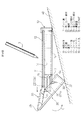
図1はカバーを閉じた状態を示す側面図、図2はカバーを開いた状態を示す側面図、図3は分解斜視図、図4はカバーを開いた状態を示す斜視図である。
図1に示すように、保護カバーを閉じた状態で機器を水平な机面40上に置いた時、機器本体10はその上面に机面40と平行でかつ水平な液晶表示面11と、机面40に接触する裏面12とを有する。
【0020】
機器本体10の両側壁には、表示面11に平行で且つこの表示面11の保護カバー開閉方向の長さ方向に沿って、この表示面11の長さに略等しい長さの1対のガイド溝13、13を有し、これらのガイド溝13、13は互いに反対側に向けて溝孔が開口している。
機器本体10の両側壁のガイド溝13、13の下側には、これらのガイド溝13、13と平行な断面が矩形の1対のガイド孔14、14が設けられている。これらのガイド孔14、14には、それぞれ断面が矩形のガイドバー15、15が入れ子式にスライド可能に挿入されている。ガイド孔14、14及びガイドバー15、15は断面が矩形であるので、ガイドバー15、15はスライド可能であるが回転しないようになっている。各ガイドバー15、15のガイド孔14、14から突き出している自由端にはピボット孔16、16がそれぞれ設けられている。
【0021】
機器本体10の液晶表示面11を開閉する保護カバーは、2つのカバー部材、即ち第1カバー部材20と第2カバー部材30とから成る。第1カバー部材20はその両側の比較的浅い立ち下がり壁21、21があり、第1カバー部材20の一端側で且つ立ち下がり壁21、21の先端部に互いの側に向いた1対の軸部22、22が設けられている。
【0022】
第1カバー部材20はその他端23の側で、適当な可撓性のシート材、例えばフィルムシートや、兆番等よりなるヒンジ部材25を介して第2カバー部材30の一端31側に、第1カバー部材20と第2カバー部材30との間が互いに枢動可能となるように連結されている。
第2カバー部材30の他端32の側は、両側に立ち下がり壁33、33を有すると共に、これらの立ち下がり壁33、33の更に他端の側に、保護カバーを閉じている時に、機器の底部の一部(図1)をなす壁部34を有し、第2カバー部材30の他端側がケース状ないし箱状の形態をなしている。また、第2カバー部材30の略中央部で且つ立ち下がり壁33、33の前記一端31に近い側には、互いの側に向いた1対のピボット軸部35、35が設けられている。
【0023】
第1カバー部材20の1対の軸部22、22は機器本体10の1対のガイド溝13、13にスライド移動可能に且つ枢動可能に嵌合している。一方、第2カバー部材30の1対の軸部34、34は、1対のガイドバー15、15の自由端に設けたピボット孔16、16がそれぞれ枢動可能に嵌合され、更に機器本体1の両側壁に1対のガイド溝13、13と平行に設けた1対のガイド溝17、17にスライド可能に嵌合されている。これらの1対のガイド溝17、17はガイド溝13、13よりかなり短いものである。
【0024】
図1には、第1カバー部材20と第2カバー部材30とから成る保護カバーが機器本体10の表示面11を閉じて保護している状態を示す。即ち、第1カバー部材20と第2カバー部材30は略平面状に、即ちヒンジ部材25を中心に約180度の関係にあり、第1カバー部材20と第2カバー部材30は協働して表示面11を覆っている。この状態では、第1カバー部材20の軸部22、22はガイド溝13、13の第1位置(13a)にあり、且つガイドバー15、15はガイド孔14、14の中に挿入された位置で且つ第2カバー部材30のピボット軸部35、35はガイド溝17、17の第1位置(17a)にある。
【0025】
この閉位置から第1カバー部材20又は第2カバー部材30を開方向(図1矢印B)へ押し開くと、ガイドバー15、15はガイド孔14、14の中でスライド動作のみ可能となるので、これに追随して第1カバー部材20の軸部22、22はガイド溝13、13をスライドし且つ第2カバー部材30のピボット軸部35、35はガイド溝17、17をスライドし、したがって第1カバー部材20及び第2カバー部材30は共に平行移動をする。第2カバー部材30の他端32の側の壁部34が機器本体10の底面に接触していることも、2つのカバー部材20、30の平行移動に寄与している。
【0026】
第2カバー部材30のピボット軸部35、35がガイド溝17、17の他端、即ち第2位置(17b)に到達すると、ガイドバー15、15はそれ以上スライド移動できなくなる。この時点では第2カバー部材30の壁部34は機器本体10の底面から離れている。その後は、第2カバー部材30の第2位置(17b)にあるピボット軸部35、35を中心として開方向(図2矢印C方向)へ回転し、これに追随して第1カバー部材20の軸部22、22はガイド溝13、13に沿って更にスライド移動しながら若干のピボット動作をする。
【0027】
第1カバー部材20の軸部22、22はガイド溝13、13の他端、即ち第2位置(13b)に到達すると、第1カバー部材20はこれ以上移動できなくなると共に、この状態で機器本体10の表示面11は完全に開かれた状態となる。また、第2カバー部材30の他端32が機器本体10の裏面12に回り込んで、機器本体10を傾斜した姿勢に支持する。
【0028】
この開放状態で、第2カバー部材30の他端32の壁部34は機器本体10の裏面12に当接していて、ストッパの役目をし、機器本体10を傾斜状態に安定して保持することができる。
以上、添付図面を参照して本発明の実施形態について詳細に説明したが、本発明は上記の実施形態に限定されるものではなく、本発明の精神ないし範囲内において種々の形態、変形、修正等が可能であることに留意すべきである。
【0029】
【発明の効果】
以上に説明したような、本発明によれば、第1カバー部材と第2カバー部材とから成る保護カバーの開閉操作は、これらのカバー部材を押し開くだけの簡単な操作で可能であり、また保護カバーを完全に開けた使用状態では、機器本体を適度に傾斜した状態で保持できるので、ペン入力等の操作がし易い態勢となる。
【図面の簡単な説明】
【図1】本発明の開閉可能なカバーを有する機器の1実施形態のカバー閉状態を示す側面図(a)及びA−A断面図(b)である。
【図2】図1に示した本発明の1実施形態のカバー開状態を示す側面図である。
【図3】図1に示した本発明の1実施形態の分解斜視図である。
【図4】図1に示した本発明の1実施形態のカバー開状態を示す斜視図である。
【図5】従来の開閉可能なカバーを有する電子機器の1例を示す概略側面図で、(a)は閉状態、(b)は開状態をそれぞれ示す。
【符号の説明】
10…機器本体
11…表示面
12…裏面
13…ガイド溝
14…ガイド孔
15…ガイドバー
16…ピボット孔
17…ガイド溝
20…第1カバー部材
22…軸部
25…ヒンジ部材
30…第2カバー部材
34…裏面壁
35…ヒンジ軸部[0001]
BACKGROUND OF THE INVENTION
The present invention relates to a device having a cover that can be opened and closed. In particular, the present invention is a small portable device such as a portable desktop electronic calculator (calculator), computer, word processor, electronic notebook or the like having an operation surface or a display surface, and a cover for opening and closing the operation surface or the display surface. It is related with the apparatus which has.
[0002]
In this kind of portable equipment, the operation surface or display surface consisting of a liquid crystal surface etc. is opened when in use and can be operated with a finger, pen, etc. Many have been used to protect the surface or display surface. In addition, such devices must be protected so that they do not damage the liquid crystal surface, etc. when not in use, and can be easily operated with a finger or pen when used. is necessary.
[0003]
[Prior art]
FIG. 5 shows an example of a pen-operated portable terminal device having a conventional protective cover. In the figure, 1 is a device main body, 2 is a liquid crystal display unit also serving as a press input unit provided on the upper surface of the device main body, 3 is a pen for inputting information to the liquid crystal display unit, and 4 is a protective cover for opening and closing the liquid crystal display unit Reference numeral 5 denotes a hinge member having two
[0004]
As illustrated, the protective cover 4 is coupled to the device main body 1 by a hinge member 5 having two
[0005]
As another conventional example, JP-A-8-16522 can selectively take a first posture covering the operation surface of the apparatus body and a second posture covering the back surface opposite to the operation surface. In an electronic device equipped with a cover, the stand can be erected on the cover so that the stand can be erected from the cover to support the device body when taking the second position. There is disclosed an electronic device that can be provided.
[0006]
[Problems to be solved by the invention]
In a conventional pen-operated portable terminal device having a protective cover as shown in FIG. 5, when used, until the protective cover 4 comes into contact with the back surface of the device body, as shown in FIG. 5 (b). In this state, for example, when the terminal device is placed on a desk surface (not shown) or the like, the liquid crystal display surface is in a horizontal state. When inputting with, there is a problem that it is difficult to perform an input operation while looking at the liquid crystal display portion because the posture is such that it looks into the liquid crystal display surface.
[0007]
Further, in the electronic device described in the above-mentioned JP-A-8-16522, by attaching the stand to the cover so that it can stand upright, when the second posture is taken, that is, when the cover is opened, the stand is removed from the cover. By standing, there is an advantage that the device body can be selectively tilted, but when using the device body tilted, the stand must be erected from the cover each time. When the user tries to store the cover after the use is finished, the stand must be stored each time, and there is a problem that the opening and closing operation of the cover is troublesome.
[0008]
Accordingly, the present invention provides a device having a protective cover that is easy to operate so that the device main body can be held in an inclined state when the protective cover is easily opened and closed and used when the protective cover is opened. Is an issue.
[0009]
[Means for Solving the Problems]
To achieve the above object, according to the present invention, a device main body having a display surface, a first cover member guided by the device main body to be slidable between a first position and a second position, A second cover member having one end pivotably coupled to the first cover member, wherein the first and second cover members cooperate to cover the display surface in the first position; A device having an openable / closable cover, wherein the other end of the second cover member wraps around the back surface of the device main body at the second position so that the device main body can be supported in an inclined posture. Is provided.
[0010]
According to this, the first and second cover members are flat in the closed position and cover the display part of the device main body, and the other end of the second cover member wraps around the back surface of the device main body in the open position. A space between the first and second cover members is maintained at a predetermined angle, and the device main body is supported in an inclined posture.
On both sides of the device main body, a pair of parallel first pairs extending in parallel with the display surface and extending between the first position and the second position along the length of the display surface in the cover opening / closing direction. One guide means and a pair of second guide means parallel to the first guide means and shorter than the first guide means are provided, and the first cover member has one end and one end of the two cover members. The other end of the first cover member is slidably and pivotally guided between the first position and the second position by the first guide means. The second cover member has the one end pivotally connected to the other end of the first cover member, the other end, and a pivot portion, and the pivot portion is formed by the second guide means. Guided to be slidable from the first position to the second position and to be pivotable at the second position When one end of the first cover member is at the first position of the first guide means and the pivot portion of the second cover member is at the first position of the second guide means, And the second cover member cooperates to be in a closed position that covers the display surface, and from the closed position, the first cover member and the second cover member have a pivot portion of the second cover member at the second guide. Translation together along the first guide means and the second guide means until the second position of the means is reached, after which the one end of the first cover member is pivotable along the first guide means And the pivot portion of the second cover member pivots at the second position of the second guide means, and one end of the first cover member reaches the second position of the first guide means. When the second cover part The other end goes around the rear surface of the device body, characterized in that it is a supportable attitude inclined to the instrument body.
[0011]
According to this, in the initial operation in which the protective cover composed of the first cover member and the second cover member is opened, both the first cover member and the second cover member are translated in the opening direction, and the next operation is performed. The first cover member further slides mainly in the opening direction, while the second cover member pivots, and the other end of the second cover member wraps around the back surface of the device body so that the device body is inclined. To support. Moreover, it moves in the closing direction of the protective cover by the opposite operation.
[0012]
The pair of first guide means are a pair of guide grooves provided on both sides of the apparatus main body, and a pair of shaft portions is provided at one end of the first cover portion, and the pair of shaft portions is connected to the one of the first guide portions. It is characterized in that it is slidably and pivotably coupled to the pair of guide grooves. In this case, the pair of guide grooves are opened in opposite directions to each other, and the pair of shaft portions of the first cover member protrudes toward each other and fits in the pair of guide grooves. Have been combined.
[0013]
Accordingly, the pair of shaft portions of the first cover member are allowed to move both in a sliding manner and in a pivotal manner without departing from the pair of guide grooves on the apparatus main body side.
The pair of second guide means includes a pair of guide holes provided on both sides of the apparatus main body, and a pair of guide bars which are inserted into the guide holes and are slidable in a nested manner. A pair of pivot portions of the second cover member are pivotally coupled to the free end of the guide bar.
[0014]
According to this, in the initial operation in which the protective cover composed of the first cover member and the second cover member is opened, only the slide movement of the second cover member is allowed, and the first cover member is also slid along with this. To do.
The pair of guide holes and the pair of guide bars have a rectangular cross section. According to this, rotation within the guide hole of the guide bar is prevented.
[0015]
The pair of pivot portions of the second cover member includes a pair of shaft portions facing inwardly toward each other, and the pair of pivot shaft portions are pivot holes provided at free ends of the pair of guide bars. It is characterized by being fitted to be pivotable. In this case, a pair of second guide grooves are provided on both sides of the device main body in parallel with the pair of guide grooves, and the pair of pivot shafts are also fitted into the second guide grooves. Yes.
[0016]
According to this, the pair of pivot shaft portions of the second cover member can slide from the first position to the second position without deviating from the pair of second guide grooves on the apparatus body side. it can.
The other end of the first cover member and the one end of the second cover member are pivotally coupled to each other by a hinge member, and the shaft of the hinge member is provided at one end of the first cover member. Further, the pair of shaft portions and the pair of shaft portions provided on the pivot portion of the second cover member are parallel to each other. In this case, the hinge member is a flexible film sheet.
[0017]
According to this, the hinge structure between the first cover member and the second cover member is simple, and a smooth pivot operation can be performed during the opening / closing operation of the protective cover.
The second cover member includes a stopper portion that contacts the back surface of the device main body at an open position of a protective cover made of the first cover member and the second cover member. According to this, the apparatus main body is stably supported in an inclined state in a use state in which the protective cover is opened.
[0018]
DETAILED DESCRIPTION OF THE INVENTION
Hereinafter, embodiments of the present invention will be described in detail with reference to FIGS.
1 to 4 show an embodiment of the present invention. The device according to the present embodiment is a small portable device such as a portable desktop electronic calculator (calculator), a computer, a word processor, an electronic notebook, and the like, and opens and closes an operation surface or a display surface (hereinafter referred to as a display surface). Applies to those with a cover for.
[0019]
1 is a side view showing a state where the cover is closed, FIG. 2 is a side view showing a state where the cover is opened, FIG. 3 is an exploded perspective view, and FIG. 4 is a perspective view showing a state where the cover is opened.
As shown in FIG. 1, when the device is placed on a
[0020]
A pair of guides having a length substantially equal to the length of the
A pair of guide holes 14, 14 having a rectangular cross section parallel to the
[0021]
The protective cover that opens and closes the liquid
[0022]
The
The
[0023]
The pair of
[0024]
FIG. 1 shows a state in which a protective cover including the
[0025]
When the
[0026]
When the
[0027]
When the
[0028]
In this open state, the
Although the embodiments of the present invention have been described in detail with reference to the accompanying drawings, the present invention is not limited to the above-described embodiments, and various forms, modifications, and modifications are within the spirit and scope of the present invention. It should be noted that etc. are possible.
[0029]
【The invention's effect】
According to the present invention as described above, the opening and closing operation of the protective cover composed of the first cover member and the second cover member can be performed by a simple operation by simply pushing and opening these cover members. In the use state in which the protective cover is completely opened, the device main body can be held in a moderately inclined state, so that an operation such as pen input is easy.
[Brief description of the drawings]
FIG. 1 is a side view (a) and a cross-sectional view (B) taken along line AA showing a cover closed state of an embodiment of an apparatus having an openable / closable cover according to the present invention.
2 is a side view showing a cover open state of the embodiment of the present invention shown in FIG. 1; FIG.
FIG. 3 is an exploded perspective view of the embodiment of the present invention shown in FIG.
4 is a perspective view showing a cover open state of the embodiment of the present invention shown in FIG. 1. FIG.
5A and 5B are schematic side views showing an example of an electronic apparatus having a conventional openable / closable cover, where FIG. 5A shows a closed state and FIG. 5B shows an open state.
[Explanation of symbols]
DESCRIPTION OF
Claims (11)
該機器本体にスライド可能に案内される第1カバー部材と、
一端が該第1カバー部材に回転可能に連結された第2カバー部材と、を具備し、
前記第1位置にて前記第1及び第2カバー部材は協働して前記表示面を覆い、且つ前記第2位置にて前記第1カバー部材は前記表示面を可視可能とさせるとともに前記第2カバー部材は前記機器本体の裏面に位置して、該機器本体を傾斜した姿勢に支持可能としたこと、を特徴とする開閉可能なカバーを有する機器。A device body having a display surface;
A first cover member which is guided slide capable to the instrument body,
End comprising a second cover member rotatably coupled to the first cover member,
In the first position, the first and second cover members cooperate to cover the display surface, and in the second position, the first cover member makes the display surface visible and the second cover member is visible . the cover member is positioned on the rear surface of the device body, the device having an openable cover that was capable of supporting the posture inclined with the instrument body, and wherein the.
前記第1カバー部材は、一端と、前記第2カバー部材の一端が回転可能に連結された他端とを有し、該第1カバー部材の一端が前記第1ガイド手段に前記第1位置と第2位置との間でスライド可能で且つ回転可能に案内され、
前記第2カバー部材は、該第1カバー部材の他端に回転可能に連結された前記一端と、前記他端と、ピボット部とを有し、該ピボット部は前記第2ガイド手段の第1位置から第2位置までスライド可能に且つ該第2位置で枢動可能に案内され、
前記第1カバー部材の一端が前記第1ガイド手段の前記第1位置にあり、且つ前記第2カバー部材のピボット部が前記第2ガイド手段の前記第1位置にあるとき、該第1及び第2カバー部材は協働して前記表示面を覆う閉位置となり、
該閉位置から前記第1カバー部材及び前記第2カバー部材は、該第2カバー部材のピボット部が前記第2ガイド手段の第2位置に到達するまで、前記第1ガイド手段及び第2ガイド手段に沿って共に平行移動し、
前記第1カバー部材の前記一端は前記第1ガイド手段に沿って回転可能にスライド移動し、前記第2カバー部材の前記ピボット部は前記第2ガイド手段の第2位置で回転し、
前記第1カバー部材の一端が前記第1ガイド手段の前記第2位置に到達した時に、前記第2カバー部材の他端が前記機器本体の裏面に位置して、該機器本体を傾斜した姿勢に支持可能であること、を特徴とする請求項1に記載の機器。A pair of first guide means parallel to the display surface and extending between the first position and the second position along the cover opening / closing direction of the display surface on both sides of the device body. And a pair of second guide means parallel to the first guide means,
The first cover member has one end and the other end rotatably connected to one end of the second cover member, and the one end of the first cover member is connected to the first guide means at the first position. Being slidable and rotatable between the second position,
The second cover member has the one end rotatably connected to the other end of the first cover member, the other end, and a pivot portion, and the pivot portion is a first portion of the second guide means. Slidable from position to second position and pivotally guided in said second position;
When one end of the first cover member is in the first position of the first guide means and the pivot portion of the second cover member is in the first position of the second guide means, the first and second The two cover members cooperate to be in a closed position covering the display surface,
The first cover member and the second cover member from the closed position until the pivot portion of the second cover member reaches the second position of the second guide member. And translate together along
The one end of the first cover member is rotatably slides along the first guide means, said pivot portion of said second cover member is rotated in a second position of said second guide means,
When one end of the first cover member reaches the second position of the first guide means, the other end of the second cover member is positioned on the back surface of the device main body so that the device main body is inclined. the apparatus of claim 1, it is possible support, characterized by.
Priority Applications (2)
| Application Number | Priority Date | Filing Date | Title |
|---|---|---|---|
| JP04236797A JP3701097B2 (en) | 1997-02-26 | 1997-02-26 | Equipment with openable / closable cover |
| US08/961,151 US6034866A (en) | 1997-02-26 | 1997-10-30 | Equipment having openable cover |
Applications Claiming Priority (1)
| Application Number | Priority Date | Filing Date | Title |
|---|---|---|---|
| JP04236797A JP3701097B2 (en) | 1997-02-26 | 1997-02-26 | Equipment with openable / closable cover |
Publications (2)
| Publication Number | Publication Date |
|---|---|
| JPH10240378A JPH10240378A (en) | 1998-09-11 |
| JP3701097B2 true JP3701097B2 (en) | 2005-09-28 |
Family
ID=12634079
Family Applications (1)
| Application Number | Title | Priority Date | Filing Date |
|---|---|---|---|
| JP04236797A Expired - Fee Related JP3701097B2 (en) | 1997-02-26 | 1997-02-26 | Equipment with openable / closable cover |
Country Status (2)
| Country | Link |
|---|---|
| US (1) | US6034866A (en) |
| JP (1) | JP3701097B2 (en) |
Families Citing this family (23)
| Publication number | Priority date | Publication date | Assignee | Title |
|---|---|---|---|---|
| US6434403B1 (en) * | 1999-02-19 | 2002-08-13 | Bodycom, Inc. | Personal digital assistant with wireless telephone |
| US6437974B1 (en) * | 2000-05-23 | 2002-08-20 | Mitsui Comtek Corp. | Freestanding electronic presentation system |
| JP4997669B2 (en) * | 2001-03-22 | 2012-08-08 | ソニー株式会社 | Display device |
| US6601815B2 (en) * | 2001-04-04 | 2003-08-05 | Hooker Furniture Corporation | Adjustable tray and method of using the same |
| US6781824B2 (en) * | 2002-01-29 | 2004-08-24 | Palm, Inc. | Encasement for handheld computer |
| US20030142471A1 (en) * | 2002-01-29 | 2003-07-31 | Palm, Inc. | Replaceable cover for handheld computer |
| US6606762B1 (en) | 2002-03-04 | 2003-08-19 | Myron Corp. | Hinge for a rotatably connected cover |
| US20050047069A1 (en) * | 2004-10-01 | 2005-03-03 | Chu Chih Hui | Universal entertainment system |
| TWM264518U (en) * | 2004-10-15 | 2005-05-11 | Hannspree Inc | Display device |
| TWM267499U (en) * | 2004-12-01 | 2005-06-11 | Tatung Co | Incline structure using for a monitor |
| EP1869537B1 (en) * | 2005-03-23 | 2017-08-23 | Marc Chase Weinstein | Device having a slidable cover |
| US7414830B2 (en) * | 2005-03-23 | 2008-08-19 | Marc Chase Weinstein | Device having a slidable cover |
| US7495895B2 (en) * | 2006-04-19 | 2009-02-24 | Carnevali Jeffrey D | Protective cover for device having touch screen |
| US7451954B1 (en) * | 2007-08-21 | 2008-11-18 | Inventec Corporation | Sliding mechanism |
| TW200912446A (en) * | 2007-09-10 | 2009-03-16 | Hannspree Inc | Liquid crystal display with adjustable view angle |
| US8845095B2 (en) | 2011-08-05 | 2014-09-30 | Nitto Denko Corporation | Optical element for correcting color blindness |
| CN103121547A (en) * | 2011-11-21 | 2013-05-29 | 深圳富泰宏精密工业有限公司 | Multifunctional protective shell |
| US8931930B2 (en) | 2013-01-29 | 2015-01-13 | Nitto Denko Corporation | Optical element for correcting color blindness |
| USD735805S1 (en) | 2013-08-21 | 2015-08-04 | Elo Touch Solutions, Inc. | Electronic device housing for a touch screen register or the like |
| TWI642346B (en) * | 2016-08-17 | 2018-11-21 | 仁寶電腦工業股份有限公司 | Electronic device having stand |
| US10244088B2 (en) * | 2016-10-11 | 2019-03-26 | Sharp Kabushiki Kaisha | Electronic device, control method of electronic device, and program |
| TWI682265B (en) * | 2017-09-25 | 2020-01-11 | 仁寶電腦工業股份有限公司 | Pivoting mechanism and electronic device |
| KR102505588B1 (en) * | 2018-10-19 | 2023-03-06 | 삼성전자 주식회사 | Electronic device including stand member |
Family Cites Families (4)
| Publication number | Priority date | Publication date | Assignee | Title |
|---|---|---|---|---|
| JPS60143997A (en) * | 1983-12-29 | 1985-07-30 | 富士通株式会社 | Supporter for writing utensil with holder |
| JPH02309414A (en) * | 1989-05-25 | 1990-12-25 | Canon Inc | Input pen device |
| JPH0344725A (en) * | 1989-07-13 | 1991-02-26 | Canon Inc | Input pen device |
| JP3050765B2 (en) * | 1994-04-26 | 2000-06-12 | シャープ株式会社 | Electronics |
-
1997
- 1997-02-26 JP JP04236797A patent/JP3701097B2/en not_active Expired - Fee Related
- 1997-10-30 US US08/961,151 patent/US6034866A/en not_active Expired - Fee Related
Also Published As
| Publication number | Publication date |
|---|---|
| US6034866A (en) | 2000-03-07 |
| JPH10240378A (en) | 1998-09-11 |
Similar Documents
| Publication | Publication Date | Title |
|---|---|---|
| JP3701097B2 (en) | Equipment with openable / closable cover | |
| US5341154A (en) | Portable personal computer | |
| US5596482A (en) | Stowable, pivotally attached palm rest and handle for a notebook computer | |
| US5818360A (en) | Configuration for a computer input device | |
| TWI251768B (en) | Portable computing device with foldable keyboard | |
| TW432310B (en) | Handheld computer keyboard system | |
| US5548478A (en) | Portable computing device having an adjustable hinge | |
| US6025986A (en) | Retractable palmrest for keyboard-equipped electronic products | |
| JP4912969B2 (en) | Electronics | |
| US6672558B2 (en) | Holding apparatus for information input devices | |
| US20040114315A1 (en) | Convertible mobile computing device | |
| JPH0719186B2 (en) | Computer and display device with input function | |
| KR20050056147A (en) | Electronic device with improved hinge | |
| JPH08314569A (en) | Portable information processor | |
| JP2002149277A (en) | Foldable portable electronic device and handle device for foldable portable electronic device | |
| JPH08185243A (en) | Information processing equipment | |
| CN103838306B (en) | Electronic device | |
| JPH08185242A (en) | Information processing equipment | |
| JPH10340134A (en) | Portable electronic equipment | |
| JP3661504B2 (en) | Information processing device | |
| JPH11212665A (en) | Thinned computer system | |
| JP3924840B2 (en) | Information processing device | |
| JP2006338459A (en) | Portable electronic apparatus | |
| JP2001125668A (en) | Hinge mechanism of notebook type personal computer | |
| JPH1065356A (en) | Electronic equipment |
Legal Events
| Date | Code | Title | Description |
|---|---|---|---|
| A977 | Report on retrieval |
Free format text: JAPANESE INTERMEDIATE CODE: A971007 Effective date: 20050425 |
|
| TRDD | Decision of grant or rejection written | ||
| A01 | Written decision to grant a patent or to grant a registration (utility model) |
Free format text: JAPANESE INTERMEDIATE CODE: A01 Effective date: 20050614 |
|
| A61 | First payment of annual fees (during grant procedure) |
Free format text: JAPANESE INTERMEDIATE CODE: A61 Effective date: 20050712 |
|
| R150 | Certificate of patent or registration of utility model |
Free format text: JAPANESE INTERMEDIATE CODE: R150 |
|
| LAPS | Cancellation because of no payment of annual fees |