JP3697111B2 - Receiver - Google Patents
Receiver Download PDFInfo
- Publication number
- JP3697111B2 JP3697111B2 JP16387999A JP16387999A JP3697111B2 JP 3697111 B2 JP3697111 B2 JP 3697111B2 JP 16387999 A JP16387999 A JP 16387999A JP 16387999 A JP16387999 A JP 16387999A JP 3697111 B2 JP3697111 B2 JP 3697111B2
- Authority
- JP
- Japan
- Prior art keywords
- synchronization
- symbol
- signal
- branch
- base station
- Prior art date
- Legal status (The legal status is an assumption and is not a legal conclusion. Google has not performed a legal analysis and makes no representation as to the accuracy of the status listed.)
- Expired - Fee Related
Links
Images


Description
【0001】
【発明の属する技術分野】
本発明は、受信装置に関し、特にOFDM方式の移動体通信に用いられる受信装置及びそのランダム・アクセス・チャネル(Random Access channel;以下、「RAch」という)区間における同期獲得方法に関する。
【0002】
【従来の技術】
移動体通信において、アクセス方式にTDMAやCDMA/TDD等の時分割方式を用いる場合、上り回線(Up Link;以下、「UL」という)と下り回線(Down Link;以下、「DL」という)とで同一の周波数を用いるため、基地局間の同期を確立する必要がある。
【0003】
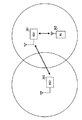
これを図3を用いて説明すると、図中BS1と表わす基地局301は、図中MSと表わす自局セル内の移動局302とだけでなく、図中BS2と表わす基地局303とも同期を確立する必要がある。
【0004】
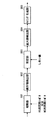
ここで、図4(a)に、時分割方式採用時の送信信号のフレームフォーマットの一例を示す。1フレームは、DL401と、UL402と、RAch403と、から成り、各DL及び各ULは、複数チャネルから成る。
【0005】
又、DL401は、基地局から移動局への送信に用いられ、UL402は、移動局から基地局への送信に用いられる。よって、基地局間の同期確立は、RAch403を用いて行われる。
【0006】
ところが、RAch403は、基地局間同期確立にのみ用いられるわけではなく、移動局との通信にもランダムに用いられる。よって、基地局装置は、RAch区間において、移動局からの信号も他の基地局からの信号も受信できるようにする必要がある。
【0007】
ここで、移動局からの送信信号のフレームフォーマットの一例を図4(b)に、基地局からの送信信号のフレームフォーマットの一例を図4(c)にそれぞれ示す。移動局からの送信信号は、MS用同期シンボル404と、パイロットシンボル405と、有効シンボル406と、から成り、基地局からの送信信号は、BS用同期シンボル407と、パイロットシンボル408と、有効シンボル409と、から成る。ここで、MS用同期シンボル404とBS用同期シンボル407は異なる既知信号であり、パイロットシンボルは位相回転検出に用いられるものであり、有効シンボルは送信データを含むシンボルである。
【0008】
そこで、従来の基地局装置は、受信処理系統を2系統持ち、それぞれ異なる既知信号を用いて同期を確立することによって、RAchにおいて移動局からの信号と基地局からの信号とのランダムな受信を実現している。
【0009】
以下、図5及び図6を用いて、従来の基地局装置に用いられる受信装置について説明する。図5は、従来の受信装置の概略構成を示す要部ブロック図であり、図6は、従来の受信装置の同期獲得部の概略構成を示す要部ブロック図である。なお、ここでは、ブランチ数は2であるものとする。
【0010】
図5において、ブランチ1であるアンテナ501及びブランチ2であるアンテナ502は、無線信号を受信し、受信処理部503及び受信処理部504は、アンテナ501及びアンテナ502によって受信された信号をそれぞれ受信処理する。
【0011】
同期獲得部505〜508は、受信信号と既知信号との相関値から同期を獲得し、シンボル同期タイミングを出力する。同期が獲得されなければシンボル同期タイミングは出力されない。ここで、同期獲得部505は、ブランチ1の受信信号に対してBS用同期シンボルを既知信号として用いて同期を検出し、以下同様に、同期獲得部506は、ブランチ2の受信信号に対してBS用同期シンボルを用い、同期獲得部507は、ブランチ1の受信信号に対してMS用同期シンボルを用い、同期獲得部508は、ブランチ2の受信信号に対してMS用同期シンボルを用いて、それぞれ同期を検出する。各同期獲得部内の構成については後述する。
【0012】
FFT処理部509は、同期獲得部505によって獲得されたシンボル同期タイミングを処理開始タイミングとして、ブランチ1の受信信号に対してFFT処理を行い、以下同様に、FFT処理部510は、同期獲得部506によって獲得されたシンボル同期タイミングを処理開始タイミングとして、ブランチ2の受信信号に対してFFT処理を行い、FFT処理部511は、同期獲得部507によって獲得されたシンボル同期タイミングを処理開始タイミングとして、ブランチ1の受信信号に対してFFT処理を行い、FFT処理部512は、同期獲得部508によって獲得されたシンボル同期タイミングを処理開始タイミングとして、ブランチ2の受信信号に対してFFT処理を行う。
【0013】
復調部513は、FFT処理部509及びFFT処理部510によってFFT処理された受信信号に対して復調処理、誤り検出、及び誤り訂正処理を行い、他の基地局から送信されたデータ(BSデータ)を出力する。復調部514は、FFT処理部511及びFFT処理部512によってFFT処理された受信信号に対して復調処理、誤り検出、及び誤り訂正処理を行い、移動局から送信されたデータ(MSデータ)を出力する。
【0014】
なお、同期が獲得されなければFFT処理も復調処理も行われない。
【0015】
次いで、図6を用いて、同期獲得部505〜508の構成について説明する。図6において、相関器601は、入力されたブランチ1の受信信号又はブランチ2の受信信号と、既知信号との相関を取る。ここで、既知信号とは、BS用同期シンボルをIFFT処理したもの、又は、MS用同期シンボルをIFFT処理したものである。
【0016】
絶対値検出部602は、相関結果の絶対値を検出し、判定部603は、相関結果の絶対値を積算し、積算値が任意のしきい値を超えるか否かを判定する。積算値がしきい値を超えれば、同期が確立されたと判断し、しきい値を超えなければ同期が取れなかったものと判断する。
【0017】
最大値検出部604は、積算された相関値が最大値を取るタイミングを検出し、タイミング生成部605は、検出されたタイミングをシンボル同期タイミングとして設定する。
【0018】
なお、FFT処理の開始タイミングは、上記のようにブランチ毎に独立して行う以外にも、全ブランチの中で最も前方で同期確立したタイミングを用いる方法や、全ブランチのタイミングを平均化したタイミングを用いるようにする方法等も提案されている。
【0019】
このように、従来の基地局装置における受信装置は、受信系統を2系統持ち、それぞれ異なる既知信号を用いて同期獲得を行うため、RAchにおいて、他の基地局からの送信信号と移動局からの送信信号とを両方ランダムに受信することができる。
【0020】
【発明が解決しようとする課題】
しかしながら、従来の受信装置においては、受信処理系統を2系統持つため、ハード規模が大きくなるという問題が生じる。
【0021】
本発明はかかる点に鑑みてなされたものであり、ハード規模が削減された受信装置及びそのRAch区間における同期獲得方法を提供することを目的とする。
【0022】
【課題を解決するための手段】
本発明では、RAch区間では、ブランチ毎に異なる既知信号を用いて同期を獲得し、同期が確立されたブランチにおけるシンボル同期タイミングを全ブランチの受信信号におけるシンボル同期タイミングとして用いる。
【0023】
【発明の実施の形態】
本発明の第1の態様に係る受信装置は、OFDM信号を複数ブランチで受信する受信手段と、各ブランチの受信信号と予め保持するブランチ毎に異なる既知信号との相関値を積算し、この積算された値が任意のしきい値を超えたブランチは同期が確立されたと判定する同期獲得判定手段と、この同期獲得判定手段によって同期が確立されたと判断されたブランチについての前記積算された値が最大値を取るタイミングを全ブランチにおけるシンボル同期タイミングとして設定する同期タイミング設定手段と、を具備する構成を採る。
【0024】
この構成によれば、ブランチ毎に異なる既知信号を用いて同期を獲得し、同期が確立されたブランチにおけるシンボル同期タイミングを全ブランチの受信信号におけるシンボル同期タイミングとして用いることによって、それぞれ異なる同期用シンボルを用いる複数の送信局のいずれから信号が送信されているか不明な時間帯においても、一つの受信処理系統において受信することができるため、基地局装置のハード規模を削減することができる。
【0025】
本発明の第2の態様に係る基地局装置は、第1の態様における受信装置を具備し、前記既知信号は、移動局が送信データに付加する同期用シンボルと、基地局が送信データに付加する同期用シンボルと、を含む構成を採る。
【0026】
本発明の第3の態様に係る基地局装置は、第2の態様において、移動局とのみ通信を行う時間帯には、各ブランチの受信信号と相関値を取る前記既知信号をすべて移動局が送信データに付加する同期用シンボルとし、移動局及び他の基地局とランダムに通信を行う時間帯には、各ブランチの受信信号との相関値を取る前記既知信号として移動局が送信データに付加する同期用シンボル及び基地局が送信データに付加する同期用シンボルを用いる構成を採る。
【0027】
これらの構成によれば、ブランチ毎に異なる既知信号を用いて同期を獲得し、同期が確立されたブランチにおけるシンボル同期タイミングを全ブランチの受信信号におけるシンボル同期タイミングとして用いることによって、一つの受信処理系統においてもRAch区間で移動局及び他の基地局からの信号をランダムに受信することができるため、基地局装置のハード規模を削減することができる。
【0028】
本発明の第4の態様に係る通信端末装置は、第2の態様又は第3の態様における基地局装置と無線通信を行う構成を採る。
【0029】
この構成によれば、移動局と基地局において異なる同期用シンボルを用いることによって、受信局である基地局がRAch区間で移動局及び他の基地局からの信号をランダムに受信することができるため、基地局装置のハード規模を削減することができる。
【0030】
本発明の第5の態様に係る同期獲得方法は、移動局又は他の基地局とランダムに通信を行う時間帯において、複数ブランチでOFDM信号を受信し、既知信号との相関値を算出する時に、所定のブランチについては既知信号として移動局が送信データに付加する同期用シンボルを用い、別の所定のブランチについては既知信号として基地局が送信データに付加する同期用シンボルを用い、算出された相関値の積算値が任意のしきい値を超えたブランチについての前記積算値が最大値を取るタイミングを全ブランチにおけるシンボル同期タイミングとするようにした。
【0031】
この方法によれば、ブランチ毎に異なる既知信号を用いて同期を獲得し、同期が確立されたブランチにおけるシンボル同期タイミングを全ブランチの受信信号におけるシンボル同期タイミングとして用いることによって、一つの受信処理系統においてもRAch区間で移動局及び他の基地局からの信号をランダムに受信することができるため、基地局装置のハード規模を削減することができる。
【0032】
以下、本発明の一実施の形態について、図面を参照して詳細に説明する。なお、ブランチ数は2であるものとする。
【0033】
以下、図1及び図2を用いて、本実施の形態に係る受信装置について説明する。図1は、本発明の一実施の形態に係る受信装置の概略構成を示す要部ブロック図であり、図2は、本発明の一実施の形態に係る受信装置の選択部の概略構成を示す要部ブロック図である。
【0034】
図1において、ブランチ1であるアンテナ101及びブランチ2であるアンテナ102は、無線信号を受信し、受信処理部103及び受信処理部104は、アンテナ101及びアンテナ102によって受信された信号をそれぞれ受信処理する。
【0035】
同期獲得部105〜106は、受信信号と既知信号との相関値から同期を獲得し、シンボル同期タイミングを出力する。同期獲得部の構成は従来と同様であるため、構成に関する詳しい説明は省略する。
【0036】
ここで、同期獲得部105は、ブランチ1の受信信号に対してMS用同期シンボルを既知信号として用いて同期を検出し、同期獲得部106は、DL区間及びUL区間においては、ブランチ2の受信信号に対してMS用同期シンボルを既知信号として用いて同期を検出し、RAch区間においては、ブランチ2の受信信号に対してBS用同期シンボルを既知信号として用いて同期を検出する。
【0037】
セレクタ107は、制御信号に基づいて、DL区間及びUL区間においては、MS用同期シンボルが同期獲得部106に入力されるように切り替えられ、RAch区間においては、BS用同期シンボルが同期獲得部106に入力されるように切り替えられる。上記制御信号は、DL/UL/RAchのいずれの時間帯であるかを示す指示信号であり、これら時間帯は基地局装置によって割り当てられるため、上記制御信号は既知である。
【0038】
選択部108は、RAch区間において、同期獲得部105及び同期獲得部106いずれによって同期が獲得されたかを検出し、識別信号として復調部111に出力し、又、同期が獲得された方のシンボル同期タイミングをFFT処理部109及びFFT処理部110に出力する。
【0039】
FFT処理部109は、選択部108によって選択されたシンボル同期タイミングに基づいてブランチ1の受信信号に対してFFT処理を行い、FFT処理部110は、選択部108によって選択されたシンボル同期タイミングに基づいてブランチ2の受信信号に対してFFT処理を行う。
【0040】
復調部111は、FFT処理部109及びFFT処理部110によってFFT処理された受信信号に対して復調処理、誤り検出、及び誤り訂正処理を行い、移動局から送信されたデータ又は他の基地局から送信されたデータを出力する。
【0041】
ここで、移動局からの受信信号と他の基地局からの受信信号ではデータ長が異なるため、復調部111は、選択部108の出力する識別信号に基づいて設定を変えた上で、復調処理、誤り検出、及び誤り訂正処理を行う
【0042】
次いで、図2を用いて、選択部108の構成について説明する。図2において、カウンタ201は、同期獲得部105において同期が獲得されると計数されるカウンタであり、カウンタ202は、同期獲得部106において同期が獲得されると計数されるカウンタである。
【0043】
比較部203は、カウンタ201の計数値とカウンタ202の計数値とを大小比較し、カウンタ201の計数値の方が大きければ受信したのは移動局から送信された信号であると判断し、カウンタ202の計数値の方が大きければ受信したのは他の基地局から送信された信号であると判断し、この判断結果を示す識別信号を出力する。
【0044】
セレクタ204は、比較部203の出力する識別信号に基づいて、同期獲得部105によって検出されたシンボル同期タイミング又は同期獲得部106によって検出されたシンボル同期タイミングのいずれかがFFT処理部109及びFFT処理部110に入力されるように切り替えられる。すなわち、移動局から受信信号であればブランチ1について検出されたタイミングが用いられ、他の基地局からの受信信号であればブランチ2について検出されたタイミングが用いられる。
【0045】
次いで、本実施の形態に係る受信装置の動作について説明する。
【0046】
OFDM信号は、アンテナ101及びアンテナ102によって受信され、受信処理部103及び受信処理部104によって受信処理される。
【0047】
基地局と移動局とが通信を行っているDL区間及びUL区間においては、MS用同期シンボルが同期獲得部106に入力され、すなわちすべての同期獲得部においてMS用同期シンボルを用いて同期の検出が行われる。
【0048】
他の基地局からの信号と移動局からの信号のいずれが受信されるか確定されないRAch区間においては、BS用同期シンボルが同期獲得部106に入力され、すなわちブランチ1とブランチ2で異なる既知信号を用いて同期の検出が行われる。
【0049】
同期が獲得されたブランチに設けられたカウンタは計数がされ、同期が獲得されなかったブランチに設けられたカウンタは0のままであることによって、同期が獲得されたブランチは比較部203によって検出される。
【0050】
同期が獲得されたブランチについて検出されたシンボル同期タイミングは、選択部108によって、FFT処理部109及びFFT処理部110の処理開始タイミングとして設定される。
【0051】
受信処理された受信信号は、FFT処理部109及びFFT処理部110によってFFT処理され、復調部111によって、復調処理、誤り検出、及び誤り訂正の処理が行われ、他の基地局から送信されたデータ、又は、移動局から送信されたデータを得る。
【0052】
このように、本実施の形態によれば、ブランチ毎に異なる既知信号を用いて同期を獲得し、同期が確立されたブランチにおけるシンボル同期タイミングを全ブランチの受信信号におけるシンボル同期タイミングとして用いることによって、一つの受信処理系統においてもRAch区間で移動局及び他の基地局からの信号をランダムに受信することができるため、基地局装置のハード規模を削減することができる。
【0053】
なお、本実施の形態においても、フレームフォーマットは、図4に示す一例に限られず、AGC用シンボルやガードインターバルが含まれても良い。
【0054】
【発明の効果】
以上説明したように、本発明によれば、ブランチ毎に異なる既知信号を用いて同期を獲得し、同期が確立されたブランチにおけるシンボル同期タイミングを全ブランチの受信信号におけるシンボル同期タイミングとして用いることによって、一つの受信処理系統においてもRAch区間で移動局及び他の基地局からの信号をランダムに受信することができるため、基地局装置のハード規模を削減することができる。
【図面の簡単な説明】
【図1】本発明の一実施の形態に係る受信装置の概略構成を示す要部ブロック図
【図2】本発明の一実施の形態に係る受信装置の選択部の概略構成を示す要部ブロック図
【図3】基地局間同期確立を説明するための模式図
【図4】(a)時分割方式採用時の送信信号のフレームフォーマットの一例を示す模式図
(b)移動局からの送信信号のフレームフォーマットの一例を示す模式図
(c)基地局からの送信信号のフレームフォーマットの一例を示す模式図
【図5】従来の受信装置の概略構成を示す要部ブロック図
【図6】従来の受信装置の同期獲得部の概略構成を示す要部ブロック図
【符号の説明】
107 セレクタ
108 選択部[0001]
BACKGROUND OF THE INVENTION
The present invention relates to a receiving apparatus, and more particularly to a receiving apparatus used for OFDM mobile communication and a synchronization acquisition method in a random access channel (hereinafter referred to as “RAch”) section.
[0002]
[Prior art]
In mobile communication, when a time division method such as TDMA or CDMA / TDD is used as an access method, an uplink (Up Link; hereinafter referred to as “UL”) and a downlink (Down Link; hereinafter referred to as “DL”) In order to use the same frequency, it is necessary to establish synchronization between base stations.
[0003]
This will be explained with reference to FIG. 3. The
[0004]
Here, FIG. 4A shows an example of a frame format of a transmission signal when the time division method is adopted. One frame includes
[0005]
DL 401 is used for transmission from the base station to the mobile station, and UL 402 is used for transmission from the mobile station to the base station. Therefore, establishment of synchronization between base stations is performed using the
[0006]
However, the RAch 403 is not only used for establishing synchronization between base stations, but is also used randomly for communication with mobile stations. Therefore, the base station device needs to be able to receive signals from the mobile station and signals from other base stations in the RAch section.
[0007]
Here, FIG. 4B shows an example of the frame format of the transmission signal from the mobile station, and FIG. 4C shows an example of the frame format of the transmission signal from the base station. The transmission signal from the mobile station is composed of an
[0008]
Therefore, the conventional base station apparatus has two reception processing systems, and establishes synchronization using different known signals, thereby allowing random reception of a signal from the mobile station and a signal from the base station in RAch. Realized.
[0009]
Hereinafter, a receiving apparatus used in a conventional base station apparatus will be described with reference to FIGS. 5 and 6. FIG. 5 is a principal block diagram showing a schematic configuration of a conventional receiving apparatus, and FIG. 6 is a principal block diagram showing a schematic configuration of a synchronization acquisition section of the conventional receiving apparatus. Here, it is assumed that the number of branches is two.
[0010]
In FIG. 5, the
[0011]
[0012]
The
[0013]
[0014]
If synchronization is not acquired, neither FFT processing nor demodulation processing is performed.
[0015]
Next, the configuration of the
[0016]
The absolute
[0017]
Maximum
[0018]
Note that the FFT processing start timing is not limited to being performed independently for each branch as described above, but is also a method using the timing that is established at the forefront among all branches, or a timing that averages the timings of all branches. There has also been proposed a method for using.
[0019]
As described above, the receiving apparatus in the conventional base station apparatus has two receiving systems and acquires synchronization using different known signals. Therefore, in RAch, transmission signals from other base stations and mobile stations receive signals. Both transmission signals can be received at random.
[0020]
[Problems to be solved by the invention]
However, since the conventional receiving apparatus has two reception processing systems, there is a problem that the hardware scale increases.
[0021]
The present invention has been made in view of this point, and an object of the present invention is to provide a receiving apparatus with a reduced hardware scale and a synchronization acquisition method in the RAch section.
[0022]
[Means for Solving the Problems]
In the present invention , in the RAch period , synchronization is acquired using different known signals for each branch, and the symbol synchronization timing in the branch where synchronization is established is used as the symbol synchronization timing in the reception signals of all branches .
[0023]
DETAILED DESCRIPTION OF THE INVENTION
The receiving apparatus according to the first aspect of the present invention integrates a correlation unit between a receiving unit that receives OFDM signals in a plurality of branches, a received signal of each branch, and a known signal that is different for each branch that is held in advance. A branch whose value exceeds an arbitrary threshold is a synchronization acquisition determination means for determining that synchronization has been established, and the integrated value for the branch for which synchronization is determined to be established by the synchronization acquisition determination means. And a synchronization timing setting means for setting the timing for taking the maximum value as the symbol synchronization timing in all branches.
[0024]
According to this configuration, different synchronization symbols are obtained by acquiring synchronization using different known signals for each branch and using the symbol synchronization timing in the branch where synchronization is established as the symbol synchronization timing in the reception signals of all branches. Since it is possible to receive in one reception processing system even in a time zone in which it is unclear from which of the plurality of transmitting stations using the base station, the hardware scale of the base station apparatus can be reduced.
[0025]
A base station apparatus according to a second aspect of the present invention includes the receiving apparatus according to the first aspect, wherein the known signal includes a synchronization symbol added to transmission data by a mobile station and a base station adds to transmission data. And a synchronization symbol.
[0026]
The base station apparatus according to a third aspect of the present invention is the base station apparatus according to the second aspect, wherein in the time zone in which only the mobile station communicates, all the known signals that take correlation values with the received signals of each branch are As a synchronization symbol to be added to the transmission data, the mobile station adds it to the transmission data as the known signal that takes a correlation value with the received signal of each branch in the time zone in which the mobile station and other base stations communicate randomly. In this configuration, a synchronization symbol to be used and a synchronization symbol to be added to transmission data by the base station are employed.
[0027]
According to these configurations, synchronization is obtained using different known signals for each branch, and the symbol synchronization timing in the branch where synchronization is established is used as the symbol synchronization timing in the reception signals of all branches, thereby allowing one reception process. Also in the system, signals from the mobile station and other base stations can be received randomly in the RAch section, so that the hardware scale of the base station apparatus can be reduced.
[0028]
The communication terminal apparatus according to the fourth aspect of the present invention employs a configuration for performing wireless communication with the base station apparatus according to the second aspect or the third aspect.
[0029]
According to this configuration, by using different synchronization symbols in the mobile station and the base station, the base station as a receiving station can receive signals from the mobile station and other base stations randomly in the RAch section. The hardware scale of the base station apparatus can be reduced.
[0030]
The synchronization acquisition method according to the fifth aspect of the present invention is a method for receiving an OFDM signal in a plurality of branches and calculating a correlation value with a known signal in a time zone in which communication with a mobile station or another base station is performed randomly. The calculation is performed using a synchronization symbol added to the transmission data by the mobile station as a known signal for a predetermined branch, and using a synchronization symbol added to the transmission data by the base station as a known signal for another predetermined branch. The timing at which the integrated value at which the integrated value of correlation values exceeds an arbitrary threshold value takes the maximum value is set as the symbol synchronization timing for all branches.
[0031]
According to this method, synchronization is obtained by using different known signals for each branch, and the symbol synchronization timing in the branch where the synchronization is established is used as the symbol synchronization timing in the reception signals of all branches, so that one reception processing system Since the signals from the mobile station and other base stations can be received at random in the RAch section, the hardware scale of the base station apparatus can be reduced.
[0032]
Hereinafter, an embodiment of the present invention will be described in detail with reference to the drawings. It is assumed that the number of branches is 2.
[0033]
Hereinafter, the receiving apparatus according to the present embodiment will be described with reference to FIG. 1 and FIG. FIG. 1 is a principal block diagram illustrating a schematic configuration of a receiving device according to an embodiment of the present invention, and FIG. 2 illustrates a schematic configuration of a selection unit of the receiving device according to an embodiment of the present invention. It is a principal part block diagram.
[0034]
In FIG. 1, the
[0035]
[0036]
Here, the
[0037]
Based on the control signal, the
[0038]
The
[0039]
The
[0040]
The
[0041]
Here, since the data length differs between the received signal from the mobile station and the received signal from another base station, the
Next, the configuration of the
[0043]
The
[0044]
Based on the identification signal output from the
[0045]
Next, the operation of the receiving apparatus according to this embodiment will be described.
[0046]
The OFDM signal is received by the
[0047]
In the DL section and the UL section in which the base station and the mobile station are communicating, the MS synchronization symbol is input to the
[0048]
In the RAch period in which it is not determined which signal from the other base station or the signal from the mobile station is received, the BS synchronization symbol is input to the
[0049]
The counter provided in the branch where the synchronization is acquired is counted, and the counter provided in the branch where the synchronization is not acquired remains 0, so that the branch where the synchronization is acquired is detected by the
[0050]
The symbol synchronization timing detected for the branch from which synchronization is acquired is set by the
[0051]
The received signal subjected to the reception processing is subjected to FFT processing by the
[0052]
As described above, according to the present embodiment, synchronization is acquired using different known signals for each branch, and the symbol synchronization timing in the branch where synchronization is established is used as the symbol synchronization timing in the reception signals of all branches. Also, even in one reception processing system, signals from the mobile station and other base stations can be received randomly in the RAch section, so that the hardware scale of the base station apparatus can be reduced.
[0053]
Also in the present embodiment, the frame format is not limited to the example shown in FIG. 4 and may include an AGC symbol and a guard interval.
[0054]
【The invention's effect】
As described above, according to the present invention, synchronization is obtained by using different known signals for each branch, and the symbol synchronization timing in the branch where synchronization is established is used as the symbol synchronization timing in the reception signals of all branches. Also, even in one reception processing system, signals from the mobile station and other base stations can be received randomly in the RAch section, so that the hardware scale of the base station apparatus can be reduced.
[Brief description of the drawings]
FIG. 1 is a principal block diagram illustrating a schematic configuration of a receiving apparatus according to an embodiment of the present invention. FIG. 2 is a principal block diagram illustrating a schematic configuration of a selection unit of the receiving apparatus according to an embodiment of the present invention. FIG. 3 is a schematic diagram for explaining establishment of synchronization between base stations. FIG. 4A is a schematic diagram showing an example of a frame format of a transmission signal when a time division method is adopted. FIG. 3B is a transmission signal from a mobile station. (C) Schematic diagram showing an example of a frame format of a transmission signal from a base station FIG. 5 is a principal block diagram showing a schematic configuration of a conventional receiving apparatus. Main block diagram showing the schematic configuration of the synchronization acquisition unit of the receiver [description of the code]
107
Claims (4)
各ブランチ毎にシンボル同期タイミングを検出する検出手段と、
シンボル同期タイミングの検出数が最も多いブランチにて検出されたシンボル同期タイミングを前記複数のブランチすべてに対するシンボル同期タイミングとして設定する設定手段と、
を具備することを特徴とする受信装置。Receiving means for receiving radio signals in a plurality of branches;
Detecting means for detecting symbol synchronization timing for each branch ;
Setting means for setting the symbol synchronization timing detected in the branch having the largest number of detected symbol synchronization timings as the symbol synchronization timing for all of the plurality of branches ;
A receiving apparatus comprising:
前記検出手段は、
受信信号と既知信号との相関値に基づいてシンボル同期タイミングを検出し、
移動局とのみ通信する時間には、すべてのブランチにおいて、既知信号として、移動局が送信データに付加する第1同期用シンボルを用い、
移動局または他の基地局と通信する時間には、所定のブランチにおいて、既知信号として、前記第1同期用シンボルを用いるとともに、他のブランチにおいて、既知信号として、他の基地局が送信データに付加する第2同期用シンボルを用いる、
ことを特徴とする基地局装置。Comprising the receiving device according to claim 1;
The detection means includes
The symbol synchronization timing is detected based on the correlation value between the received signal and the known signal,
At the time of communication only with the mobile station, the first synchronization symbol added to the transmission data by the mobile station is used as a known signal in all branches,
At the time of communication with the mobile station or another base station , the first synchronization symbol is used as a known signal in a predetermined branch, and the other base station transmits the transmitted data as a known signal in another branch. Using a second synchronization symbol to be added,
A base station apparatus.
ことを特徴とする同期獲得方法。In a time when communicating with a mobile station or a base station , when a radio signal is received by a plurality of branches and synchronization is acquired based on a correlation value between the received signal and a known signal , the predetermined branch is used as a known signal. , using a synchronization signal which the mobile station is added to the transmission data, for the other branches, as a known signal, Ru using the synchronization signal from the base station is added to the transmission data,
A synchronization acquisition method characterized by the above.
Priority Applications (1)
| Application Number | Priority Date | Filing Date | Title |
|---|---|---|---|
| JP16387999A JP3697111B2 (en) | 1999-06-10 | 1999-06-10 | Receiver |
Applications Claiming Priority (1)
| Application Number | Priority Date | Filing Date | Title |
|---|---|---|---|
| JP16387999A JP3697111B2 (en) | 1999-06-10 | 1999-06-10 | Receiver |
Publications (2)
| Publication Number | Publication Date |
|---|---|
| JP2000354020A JP2000354020A (en) | 2000-12-19 |
| JP3697111B2 true JP3697111B2 (en) | 2005-09-21 |
Family
ID=15782534
Family Applications (1)
| Application Number | Title | Priority Date | Filing Date |
|---|---|---|---|
| JP16387999A Expired - Fee Related JP3697111B2 (en) | 1999-06-10 | 1999-06-10 | Receiver |
Country Status (1)
| Country | Link |
|---|---|
| JP (1) | JP3697111B2 (en) |
Cited By (1)
| Publication number | Priority date | Publication date | Assignee | Title |
|---|---|---|---|---|
| JP2008153775A (en) * | 2006-12-14 | 2008-07-03 | Advantest Corp | Symbol synchronizing device, symbol synchronizing method, and testing device |
Families Citing this family (3)
| Publication number | Priority date | Publication date | Assignee | Title |
|---|---|---|---|---|
| JP4300204B2 (en) * | 2005-06-30 | 2009-07-22 | 株式会社東芝 | Wireless communication device |
| JP4636162B2 (en) * | 2008-10-10 | 2011-02-23 | ソニー株式会社 | Wireless communication apparatus and wireless communication method |
| JP6217310B2 (en) * | 2013-10-25 | 2017-10-25 | 沖電気工業株式会社 | Receiver, symbol timing synchronization apparatus, and symbol timing synchronization method |
-
1999
- 1999-06-10 JP JP16387999A patent/JP3697111B2/en not_active Expired - Fee Related
Cited By (1)
| Publication number | Priority date | Publication date | Assignee | Title |
|---|---|---|---|---|
| JP2008153775A (en) * | 2006-12-14 | 2008-07-03 | Advantest Corp | Symbol synchronizing device, symbol synchronizing method, and testing device |
Also Published As
| Publication number | Publication date |
|---|---|
| JP2000354020A (en) | 2000-12-19 |
Similar Documents
| Publication | Publication Date | Title |
|---|---|---|
| CN103782632B (en) | Small region search method in wireless communication system | |
| EP2312768B1 (en) | Communications in an asynchronous wireless network | |
| JP4077162B2 (en) | Uplink timing synchronization and access control for multi-access wireless communication systems | |
| EP0917305B1 (en) | Communication method, transmitting method, receiving method, base station and terminal device | |
| EP2184867B1 (en) | Wireless communication device with improved synchronous timing detection of different base stations | |
| JP2005506734A (en) | Acquisition circuit applicable to low chip rate option for mobile communication system | |
| EP2127190B1 (en) | Robust synchronization for time division duplex signal | |
| JP3858433B2 (en) | Pilot signal detection method and receiver | |
| KR20160131298A (en) | Method and apparatus for receiving signals in device-to-device wireless communication | |
| RU2007116169A (en) | MOBILE WIRELESS COMMUNICATION DEVICE, WIRELESS COMMUNICATION DEVICE AND METHOD OF PROCESSING DATA FROM COMMUNICATION CHANNELS | |
| JP2005143101A (en) | Method of idle mode control in ofdm system | |
| US20190335261A1 (en) | Wireless microphone and/or in-ear monitoring system and method for controlling a wireless microphone and/or in-ear monitoring system | |
| JP2008517537A (en) | Improved beacon signal to facilitate signal detection and timing synchronization | |
| JP3783078B2 (en) | Improved synchronization with receiver transmitter using early and late test during coarse synchronization | |
| JP3697111B2 (en) | Receiver | |
| JPH08242482A (en) | Communication system | |
| JP2001078268A (en) | Slot system for pilot channel of radio mobile communication system | |
| KR20000012033A (en) | A receiving apparatus for a random access channel of a CDMA mobile communication system | |
| KR101625523B1 (en) | Apparatus and method for detecting cell in wireless communication system | |
| CN110022603B (en) | Synchronization method and device between base stations | |
| JP4354041B2 (en) | Wireless terminal device | |
| JPH09307964A (en) | Method for intermittent reception of incoming call signal in mobile communication, and base station equipment and mobile equipment | |
| JP2000050351A (en) | Mobile communication device and method for establishing synchronization in mobile communication | |
| KR100524537B1 (en) | Method for signaling the start of a logical channel in a jointly used physical transmission channel of a radio communications system | |
| JP4298918B2 (en) | Method for digitally transmitting data over a wireless communication network and receiver for receiving data transmitted by this method |
Legal Events
| Date | Code | Title | Description |
|---|---|---|---|
| A977 | Report on retrieval |
Free format text: JAPANESE INTERMEDIATE CODE: A971007 Effective date: 20041215 |
|
| A131 | Notification of reasons for refusal |
Free format text: JAPANESE INTERMEDIATE CODE: A131 Effective date: 20050118 |
|
| A521 | Written amendment |
Free format text: JAPANESE INTERMEDIATE CODE: A523 Effective date: 20050210 |
|
| TRDD | Decision of grant or rejection written | ||
| A01 | Written decision to grant a patent or to grant a registration (utility model) |
Free format text: JAPANESE INTERMEDIATE CODE: A01 Effective date: 20050628 |
|
| A61 | First payment of annual fees (during grant procedure) |
Free format text: JAPANESE INTERMEDIATE CODE: A61 Effective date: 20050701 |
|
| R150 | Certificate of patent or registration of utility model |
Free format text: JAPANESE INTERMEDIATE CODE: R150 |
|
| FPAY | Renewal fee payment (event date is renewal date of database) |
Free format text: PAYMENT UNTIL: 20090708 Year of fee payment: 4 |
|
| FPAY | Renewal fee payment (event date is renewal date of database) |
Free format text: PAYMENT UNTIL: 20090708 Year of fee payment: 4 |
|
| FPAY | Renewal fee payment (event date is renewal date of database) |
Free format text: PAYMENT UNTIL: 20100708 Year of fee payment: 5 |
|
| FPAY | Renewal fee payment (event date is renewal date of database) |
Free format text: PAYMENT UNTIL: 20110708 Year of fee payment: 6 |
|
| FPAY | Renewal fee payment (event date is renewal date of database) |
Free format text: PAYMENT UNTIL: 20110708 Year of fee payment: 6 |
|
| FPAY | Renewal fee payment (event date is renewal date of database) |
Free format text: PAYMENT UNTIL: 20120708 Year of fee payment: 7 |
|
| FPAY | Renewal fee payment (event date is renewal date of database) |
Free format text: PAYMENT UNTIL: 20120708 Year of fee payment: 7 |
|
| FPAY | Renewal fee payment (event date is renewal date of database) |
Free format text: PAYMENT UNTIL: 20130708 Year of fee payment: 8 |
|
| LAPS | Cancellation because of no payment of annual fees |