JP3696773B2 - Building - Google Patents
Building Download PDFInfo
- Publication number
- JP3696773B2 JP3696773B2 JP2000155131A JP2000155131A JP3696773B2 JP 3696773 B2 JP3696773 B2 JP 3696773B2 JP 2000155131 A JP2000155131 A JP 2000155131A JP 2000155131 A JP2000155131 A JP 2000155131A JP 3696773 B2 JP3696773 B2 JP 3696773B2
- Authority
- JP
- Japan
- Prior art keywords
- wooden base
- humidity control
- building
- heat storage
- storage layer
- Prior art date
- Legal status (The legal status is an assumption and is not a legal conclusion. Google has not performed a legal analysis and makes no representation as to the accuracy of the status listed.)
- Expired - Fee Related
Links
Images


Classifications
-
- Y—GENERAL TAGGING OF NEW TECHNOLOGICAL DEVELOPMENTS; GENERAL TAGGING OF CROSS-SECTIONAL TECHNOLOGIES SPANNING OVER SEVERAL SECTIONS OF THE IPC; TECHNICAL SUBJECTS COVERED BY FORMER USPC CROSS-REFERENCE ART COLLECTIONS [XRACs] AND DIGESTS
- Y02—TECHNOLOGIES OR APPLICATIONS FOR MITIGATION OR ADAPTATION AGAINST CLIMATE CHANGE
- Y02A—TECHNOLOGIES FOR ADAPTATION TO CLIMATE CHANGE
- Y02A30/00—Adapting or protecting infrastructure or their operation
- Y02A30/24—Structural elements or technologies for improving thermal insulation
-
- Y—GENERAL TAGGING OF NEW TECHNOLOGICAL DEVELOPMENTS; GENERAL TAGGING OF CROSS-SECTIONAL TECHNOLOGIES SPANNING OVER SEVERAL SECTIONS OF THE IPC; TECHNICAL SUBJECTS COVERED BY FORMER USPC CROSS-REFERENCE ART COLLECTIONS [XRACs] AND DIGESTS
- Y02—TECHNOLOGIES OR APPLICATIONS FOR MITIGATION OR ADAPTATION AGAINST CLIMATE CHANGE
- Y02B—CLIMATE CHANGE MITIGATION TECHNOLOGIES RELATED TO BUILDINGS, e.g. HOUSING, HOUSE APPLIANCES OR RELATED END-USER APPLICATIONS
- Y02B80/00—Architectural or constructional elements improving the thermal performance of buildings
Description
【0001】
【発明の属する技術分野】
本発明は、基礎部分の構造に特徴を有する建築物に関する。
【0002】
【従来の技術】
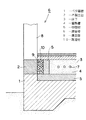
従来、図3に示したように、コンクリート製のベタ基礎1の上に木製土台2を設置し、また、床下3に蓄熱コンクリートなどの蓄熱層4を形成し、その蓄熱層4と前記木製土台2の間に断熱性の中間材5を介在させるようにした建築物6がある。そして、蓄熱層4に通した熱交換パイプ7に対し加熱した液体又は気体を循環させ、もって蓄熱層4に蓄熱して床下3から室内を暖めるようにしている。
【0003】
【発明が解決しようとする課題】
前記中間材5は断熱性を有するが、それでも蓄熱層4から熱が伝わるため木製土台2との接触面に結露が生じやすい。そして結露した水分は木製土台2に吸収されるから、木製土台2の含水率が増大し、白蟻などの害虫やカビなどの被害を受ける危険性が高まる。
【0004】
本発明は上記に鑑みなされたもので、その目的は床又は床下に蓄熱層を有する建築物において、木製土台が結露の害を受けないようにすることにある。
【0005】
【課題を解決するための手段】
上記の目的を達成するため本発明は、布基礎又はベタ基礎の上に木製土台を設置すると共に床又は床下に蓄熱層を形成し、さらに蓄熱層と前記木製土台の間に中間材を介在させてなる建築物において、前記木製土台と中間材の間に溝空間を形成し、その溝空間に調湿材を充填するようにした建築物を提供する。
【0006】
中間材と木製土台の間に調湿材が介在するため、仮に中間材の外表面に結露が生じたとしても調湿材が吸収して木製土台への染み込みを防止する。また、逆に木製土台が乾燥しすぎた場合には調湿材が保有水分を放出するため木製土台の乾きすぎを防止する。
【0007】
また、請求項2のように調湿材を炭又は活性炭にするとよい。炭又は活性炭には殺菌作用や防虫作用があるため、木製土台に対する防蟻効果や防カビ効果を高めることができる。
【0008】
また、請求項3のように調湿材を粒状又は棒状にするとよい。そうすることにより充填状態で調湿材同士の間に自然な隙間ができて通気性が高まり尚且つ吸放湿のための面積が増大するため、前記各効果がより一層向上する。
【0009】
【発明の実施の形態】
以下に本発明の実施の形態を図面を参照しつつ説明する。なお、図1は建築物の基礎部分を示す断面図、図2は図1を立体的に示した斜視図である。
【0010】
図示した建築物6は、コンクリート製のベタ基礎1の上に木製土台2を設置し、床下3に蓄熱コンクリートなどの蓄熱層4を形成してなる。木製土台2は建築物6の本体とベタ基礎1を連結するためのものであり、従って木製土台2には柱8などが取り付けられる。
【0011】
蓄熱層4には熱交換パイプ7が埋設されており、その熱交換パイプ7に太陽熱やボイラー或いは電熱器で加熱した液体又は気体を循環させて蓄熱層4に蓄熱する。また、蓄熱層4を土間形式にして蓄熱層4自体が床を構成する場合もあり、そうした場合には蓄熱層4自体に日光を当てて加熱・蓄熱する。
【0012】
蓄熱層4の底面とベタ基礎1の上面の間及び蓄熱層4の外周面には断熱性のある例えば押出法ポリスチレンフォーム製の中間材5が設けられていて、蓄熱層4を保温する。
【0013】
しかして、本発明は木製土台2と中間材5の間に溝空間9を形成し、その溝空間9に調湿材10を充填するようにしたことを特徴とする。調湿材10は適度な大きさに砕いた粒状の炭を使用し、それを溝空間9に敷き詰める。この状態では調湿材10の粒同士の間に自然な隙間ができて通気性が高まり尚且つ水分の吸放出面が増大するため、調湿作用にとって好ましい結果をもたらす。なお、炭の粒の大きさや形状(定形、不定形のいずれも可)は特に限定されるものではなく、実際には短い棒状の炭を使用してもよい。そのような棒状の形態でも必要な調湿作用は確保できる。
【0014】
次に本発明の建築物6の作用について説明する。先ず、蓄熱層4の熱交換パイプ7に加熱した液体又は気体を循環させると蓄熱層4の温度が上昇する。これに伴い中間材5の温度もある程度上昇するが、調湿材10が溝空間9の内部を乾燥状態にしているため、中間材5の外表面に結露が生じにくい。また、仮に中間材5の外表面に結露が生じたとしても、直ぐに調湿材10が吸収するため、木製土台2の含水率の上昇が抑制できる。一方、乾燥状態が続いて木製土台2の含水率が低下した場合は、調湿材10の内部にある水分が少しずつ放出されるため、木製土台2の含水率が適正に保たれる。
【0015】
さらにまた、炭や活性炭には殺菌作用や防虫作用があって木製土台2に対する防蟻効果や防カビ効果が高まるため、アレルギーを引き起こすような化学物質を使用する必要がなくなる。
【0016】
以上本発明を実施の形態について説明したが、もちろん本発明は上記実施形態に限定されるものではない。例えば実施形態では調湿材10として炭を使用したが、それ以外にも活性炭の他、活性アルミナなどのセラミックス、珪藻土、天然の多孔質材、素焼の陶磁器などを使用してもよい。また、実施形態では調湿材10を粒状や棒状にしたが、例えば調湿材10を溝空間9に合致する形状のブロック形態とし、それを溝空間9に並べるようにしてもよい。
【0017】
また、実施形態では木製土台2として建築物6の周囲を形成するいわゆる「側土台」について示したが、建築物6の部屋を間仕切る「間仕切土台」についても同様に適用できる。なお、間仕切土台において隣り合う部屋同士の夫々に蓄熱層4,4がある場合には、木製土台2の両側に溝空間9を設ければよい。また、実施形態ではベタ基礎1について説明したが、布基礎でも同様である。
【0018】
【発明の効果】
本発明の建築物は、中間材と木製土台の間に調湿材を介在させるようにしたため、仮に中間材の外表面に結露が生じたとしても調湿材が水分を吸収して木製土台への染み込みを防止する。また、逆に木製土台が乾燥した場合には調湿材が保有水分を放出するため木製土台の乾きすぎをも防止する。従って木製土台が常に良好な状態に保たれるから、害虫やカビの被害を受けにくく、結果的に建築物の耐久性向上に優れた効果を発揮する。
【0019】
また、請求項2のように調湿材を炭又は活性炭にすれば、炭又は活性炭に備わっている殺菌作用や防虫作用により、木製土台に対する防蟻効果や防カビ効果が高まるため、有害な化学物質を使用する必要がなくなり、建築物の安全性向上にも優れた効果を発揮する。
【0020】
また、請求項3のように調湿材を粒状又は棒状にすれば、調湿材同士の間に隙間ができて通気性が高まると共に吸放湿面が増大するため、前記各効果がより一層向上する。
【図面の簡単な説明】
【図1】 建築物の基礎部分を示す断面図である。
【図2】 図1を立体的に示した斜視図である。
【図3】 従来の建築物の基礎部分を示す断面図である。
【符号の説明】
1 …ベタ基礎(又は布基礎)
2 …木製土台
3 …床下
4 …蓄熱層
5 …中間材
6 …建築物
9 …溝空間
10…調湿材[0001]
BACKGROUND OF THE INVENTION
The present invention relates to a building having a feature in the structure of a foundation portion.
[0002]
[Prior art]
Conventionally, as shown in FIG. 3, a
[0003]
[Problems to be solved by the invention]
The
[0004]
The present invention has been made in view of the above, and an object thereof is to prevent a wooden base from being affected by condensation in a building having a heat storage layer on the floor or under the floor.
[0005]
[Means for Solving the Problems]
In order to achieve the above object, the present invention provides a wooden base on a cloth foundation or a solid foundation, forms a heat storage layer on the floor or under the floor, and further interposes an intermediate material between the heat storage layer and the wooden base. In such a building, there is provided a building in which a groove space is formed between the wooden base and the intermediate material, and the groove space is filled with a humidity control material.
[0006]
Since the humidity control material is interposed between the intermediate material and the wooden base, even if condensation occurs on the outer surface of the intermediate material, the humidity control material absorbs and prevents the penetration into the wooden base. Conversely, when the wooden base is too dry, the humidity control material releases the retained moisture, thereby preventing the wooden base from being dried too much.
[0007]
Moreover, it is good to make charcoal or activated carbon into a humidity control material like
[0008]
Moreover, it is good to make a humidity-control material granular or stick-like like
[0009]
DETAILED DESCRIPTION OF THE INVENTION
Embodiments of the present invention will be described below with reference to the drawings. 1 is a cross-sectional view showing a basic portion of a building, and FIG. 2 is a perspective view showing FIG. 1 in three dimensions.
[0010]
The illustrated
[0011]
A
[0012]
Between the bottom surface of the
[0013]
Therefore, the present invention is characterized in that a
[0014]
Next, the effect | action of the
[0015]
Furthermore, since charcoal and activated carbon have a bactericidal action and an insecticidal action, and the ant-proofing effect and the mold-proofing effect on the
[0016]
The embodiments of the present invention have been described above, but the present invention is of course not limited to the above embodiments. For example, in the embodiment, charcoal is used as the
[0017]
In the embodiment, the so-called “side base” that forms the periphery of the
[0018]
【The invention's effect】
In the building of the present invention, since the humidity control material is interposed between the intermediate material and the wooden base, even if condensation occurs on the outer surface of the intermediate material, the humidity control material absorbs moisture into the wooden base. Prevent soaking in. On the contrary, when the wooden base is dried, the humidity control material releases the retained water, thereby preventing the wooden base from being dried too much. Therefore, the wooden base is always kept in a good state, so that it is not easily damaged by insects and fungi, and as a result, it has an excellent effect on improving the durability of the building.
[0019]
Further, if the humidity control material is charcoal or activated carbon as in
[0020]
Further, if the humidity control material is made granular or rod-like as in
[Brief description of the drawings]
FIG. 1 is a cross-sectional view showing a foundation portion of a building.
FIG. 2 is a perspective view showing FIG. 1 in three dimensions.
FIG. 3 is a cross-sectional view showing a basic portion of a conventional building.
[Explanation of symbols]
1 ... Solid foundation (or cloth foundation)
2 ...
Claims (3)
前記木製土台と中間材の間に溝空間を形成し、その溝空間に調湿材を充填するようにしたことを特徴とする建築物。In a building in which a wooden base is installed on a cloth foundation or a solid foundation, a heat storage layer is formed on the floor or under the floor, and an intermediate material is interposed between the heat storage layer and the wooden base.
A building characterized in that a groove space is formed between the wooden base and the intermediate material, and the groove space is filled with a humidity control material.
Priority Applications (1)
| Application Number | Priority Date | Filing Date | Title |
|---|---|---|---|
| JP2000155131A JP3696773B2 (en) | 2000-05-25 | 2000-05-25 | Building |
Applications Claiming Priority (1)
| Application Number | Priority Date | Filing Date | Title |
|---|---|---|---|
| JP2000155131A JP3696773B2 (en) | 2000-05-25 | 2000-05-25 | Building |
Publications (2)
| Publication Number | Publication Date |
|---|---|
| JP2001336225A JP2001336225A (en) | 2001-12-07 |
| JP3696773B2 true JP3696773B2 (en) | 2005-09-21 |
Family
ID=18660119
Family Applications (1)
| Application Number | Title | Priority Date | Filing Date |
|---|---|---|---|
| JP2000155131A Expired - Fee Related JP3696773B2 (en) | 2000-05-25 | 2000-05-25 | Building |
Country Status (1)
| Country | Link |
|---|---|
| JP (1) | JP3696773B2 (en) |
Families Citing this family (1)
| Publication number | Priority date | Publication date | Assignee | Title |
|---|---|---|---|---|
| JP3984182B2 (en) * | 2003-03-17 | 2007-10-03 | 株式会社ユニバーサルホーム | Floor foundation construction method |
Family Cites Families (6)
| Publication number | Priority date | Publication date | Assignee | Title |
|---|---|---|---|---|
| JPS6099415U (en) * | 1983-12-12 | 1985-07-06 | ミサワホ−ム株式会社 | Piping structure for floor heating with earthen floor |
| JPS61120812U (en) * | 1985-01-14 | 1986-07-30 | ||
| JP3027105U (en) * | 1996-01-22 | 1996-07-30 | 隆 古野 | Humidity control / deodorant / heat retention mat for buildings containing fine activated carbon |
| JPH09324939A (en) * | 1996-06-06 | 1997-12-16 | Sekisui House Ltd | Dehumidifying-ventilating device for cooling/heating of heat storage type |
| JPH11200646A (en) * | 1998-01-06 | 1999-07-27 | Sado Takao | Energy saving healthy residence |
| JPH11222947A (en) * | 1998-02-06 | 1999-08-17 | Etsuo Kobayashi | Porous filler, building member, panel member, and manufacture thereof |
-
2000
- 2000-05-25 JP JP2000155131A patent/JP3696773B2/en not_active Expired - Fee Related
Also Published As
| Publication number | Publication date |
|---|---|
| JP2001336225A (en) | 2001-12-07 |
Similar Documents
| Publication | Publication Date | Title |
|---|---|---|
| JP2018524540A (en) | Harvesting energy from humidity fluctuations | |
| JP3696773B2 (en) | Building | |
| JP6058569B2 (en) | Building materials | |
| JPH01224595A (en) | Improvement in heat-insulating material | |
| JP2001311232A (en) | Temperature and humidity adjustment function attached house | |
| JP2002021211A (en) | Dew condensation preventive wall structure | |
| JP3183289U (en) | Furniture with composite functional paulownia wood | |
| JP2008038579A (en) | Humidity control member | |
| JPH02229343A (en) | Structure of wall and floor | |
| KR200379098Y1 (en) | Heat insulating board for building | |
| JP2502067Y2 (en) | Interior plate and wall interior structure | |
| JP3980905B2 (en) | Humidity control method | |
| JPS6011208Y2 (en) | Condensation drainage sheet for insulation walls | |
| JPH0718831Y2 (en) | Mat with activated carbon | |
| JP3187597U (en) | Underfloor sealing structure of building and building having the underfloor sealing structure | |
| JP3972969B2 (en) | Wall structure | |
| JP2008045325A (en) | Antisweat wall structure | |
| JP2594276Y2 (en) | Humidity control outer wall structure | |
| JP2003082779A (en) | House | |
| JPH0442644Y2 (en) | ||
| JPH0649916A (en) | Inner wall material | |
| JP3103509B2 (en) | Insulation and humidity control sheet for construction | |
| JPS5846973B2 (en) | Methods for controlling indoor humidity in buildings and preventing condensation on walls | |
| JPS639720Y2 (en) | ||
| JPS6234894B2 (en) |
Legal Events
| Date | Code | Title | Description |
|---|---|---|---|
| A131 | Notification of reasons for refusal |
Free format text: JAPANESE INTERMEDIATE CODE: A131 Effective date: 20040316 |
|
| A131 | Notification of reasons for refusal |
Free format text: JAPANESE INTERMEDIATE CODE: A131 Effective date: 20041228 |
|
| TRDD | Decision of grant or rejection written | ||
| A01 | Written decision to grant a patent or to grant a registration (utility model) |
Free format text: JAPANESE INTERMEDIATE CODE: A01 Effective date: 20050628 |
|
| A61 | First payment of annual fees (during grant procedure) |
Free format text: JAPANESE INTERMEDIATE CODE: A61 Effective date: 20050630 |
|
| R150 | Certificate of patent or registration of utility model |
Free format text: JAPANESE INTERMEDIATE CODE: R150 |
|
| FPAY | Renewal fee payment (event date is renewal date of database) |
Free format text: PAYMENT UNTIL: 20100708 Year of fee payment: 5 |
|
| FPAY | Renewal fee payment (event date is renewal date of database) |
Free format text: PAYMENT UNTIL: 20120708 Year of fee payment: 7 |
|
| FPAY | Renewal fee payment (event date is renewal date of database) |
Free format text: PAYMENT UNTIL: 20140708 Year of fee payment: 9 |
|
| R250 | Receipt of annual fees |
Free format text: JAPANESE INTERMEDIATE CODE: R250 |
|
| R250 | Receipt of annual fees |
Free format text: JAPANESE INTERMEDIATE CODE: R250 |
|
| R250 | Receipt of annual fees |
Free format text: JAPANESE INTERMEDIATE CODE: R250 |
|
| LAPS | Cancellation because of no payment of annual fees |