JP3689331B2 - Heating method for cylindrical metal coil - Google Patents
Heating method for cylindrical metal coil Download PDFInfo
- Publication number
- JP3689331B2 JP3689331B2 JP2000394611A JP2000394611A JP3689331B2 JP 3689331 B2 JP3689331 B2 JP 3689331B2 JP 2000394611 A JP2000394611 A JP 2000394611A JP 2000394611 A JP2000394611 A JP 2000394611A JP 3689331 B2 JP3689331 B2 JP 3689331B2
- Authority
- JP
- Japan
- Prior art keywords
- coil
- heating
- cylindrical metal
- metal coil
- iron core
- Prior art date
- Legal status (The legal status is an assumption and is not a legal conclusion. Google has not performed a legal analysis and makes no representation as to the accuracy of the status listed.)
- Expired - Fee Related
Links
Images
Classifications
-
- Y—GENERAL TAGGING OF NEW TECHNOLOGICAL DEVELOPMENTS; GENERAL TAGGING OF CROSS-SECTIONAL TECHNOLOGIES SPANNING OVER SEVERAL SECTIONS OF THE IPC; TECHNICAL SUBJECTS COVERED BY FORMER USPC CROSS-REFERENCE ART COLLECTIONS [XRACs] AND DIGESTS
- Y02—TECHNOLOGIES OR APPLICATIONS FOR MITIGATION OR ADAPTATION AGAINST CLIMATE CHANGE
- Y02P—CLIMATE CHANGE MITIGATION TECHNOLOGIES IN THE PRODUCTION OR PROCESSING OF GOODS
- Y02P10/00—Technologies related to metal processing
- Y02P10/25—Process efficiency
Landscapes
- General Induction Heating (AREA)
- Heat Treatment Of Strip Materials And Filament Materials (AREA)
Description
【0001】
【発明の属する技術分野】
本発明は、鋼板やアルミ板等コイル状に巻いた円筒状金属コイルを加熱する際、局部的な加熱から均一加熱までを効果的に行うことのできる加熱方法に関する。
【0002】
【従来の技術】
従来より、円筒状金属コイルの加熱は、バッチ炉に入れガス加熱やパネルヒーターにより加熱する方法がほとんどである。バッチ加熱は、雰囲気が制御でき、高温で焼鈍できることなどから、連続焼鈍装置では加熱できない特殊な材質のものや、品質が厳しいものなどに適用されている。しかし、円筒状金属コイルのバッチ焼鈍は、基本的には金属の塊を外部から加熱することになるため、加熱時間が非常に長くなるとともに、温度偏差が大きくつきやすいため長時間にわたって均熱化する必要があるほか、加熱効率が極めて低い等の問題があり、コイル内の温度分布を制御することが極めて難しい状態であった。
【0003】
この問題を解決するため通電加熱を採用する事が提唱されている。たとえば、特開平6−10067号公報にはコイルの両端から通電することが、また特開平5−171259号公報には拡縮機構を有する内外電極により直接通電することが記載されている。また、電気を使って加熱する方法としては、特開昭61−19097号公報にコイル内に鉄心を通し、誘導加熱する方法が提唱されている。
【0004】
【発明が解決しようとする課題】
しかし、通電加熱する方法では、特開平6−10067号公報の場合、コイルと電極の接触面が均一に当たりにくいため局部的に発熱し、コイルに損傷を与えるという問題がある。また、特開平6−10067号公報及び特開平5−171259号公報では、両者とも大きな断面積を有する物体であるため抵抗が小さく、極めて大きな電流を流さないと発熱できなく、時間をかけないと加熱しにくいという問題、大電流通電に関わる設備上の問題がある。また、特開昭61−19097号公報では、誘導加熱が効果的に行われるのは、周波数に応じた浸透深さまでの部分のみで、それ以外の部分は、伝熱により熱が伝わるため温度分布を制御することが難しいという問題や、押し付け部以外のストリップ層間を流れる電流により層間でスパークが発生するという問題がある。
【0005】
そこで、本発明は、効果的にコイル厚み方向の温度分布を制御するとともに、効率がよくストリップ層間のスパーク発生もない高品位の加熱を短時間で安定してできる円筒状金属コイルの加熱方法を提供することを目的とする。
【0006】
【課題を解決するための手段】
本発明の要旨は下記の通りである。
(1)金属帯板の板間を絶縁して巻き円筒状にしたコイルの内側を貫通する鉄心と、該鉄心と該円筒状金属コイルの外で連結する鉄心とで磁気回路を形成し、該円筒状金属コイルの内側を貫通する鉄心に一次コイルを巻くとともに、該円筒状金属コイルの最外周部の金属帯板と最内周部の金属帯板とを導電部材で短絡し二次回路とすることによりトランスを構成し、該一次コイルに50〜10000Hzの範囲で、円筒状金属コイル内側に渦電流を発生させる高周波とそれよりも低い周波数の、異なる少なくとも2つの周波数の電流を通電することにより円筒状金属コイルを加熱することを特徴とする円筒状金属コイルの加熱方法。
(2)上記(1)に記載の加熱方法において、鉄心に独立した複数の一次コイルを巻き、各々に50〜10000Hzの範囲で、円筒状金属コイル内側に渦電流を発生させる高周波とそれよりも低い周波数の、異なる2つ以上の周波数の電流を同時に通電し、該円筒状金属コイルを加熱することを特徴とする円筒状金属コイルの加熱方法。
である。
【0007】
【発明の実施の形態】
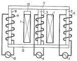
以下、本発明の実施の形態を図面を用いて説明する。なお、説明では特に加熱雰囲気を特定していないが、酸化雰囲気でもまた非酸化雰囲気でも構わない。 図1は、本発明による円筒状金属コイルの熱処理装置を説明する模式断面図である。図示の説明では、3脚のトランスの例を示すが、2脚でも多脚でも構わない。
【0008】
帯状の金属を絶縁するように巻いた円筒状金属コイル1の内側の空間部分には、良磁性体、たとえば電磁鋼板等でつくられた鉄心2が貫通し、鉄心2と鉄心11,5,12,8とで磁気回路を形成する。円筒状金属コイル1の中に鉄心2を貫通させるため、例えば鉄心11は、鉄心2から分離できるように形成し、円筒状金属コイル1を先に鉄心2に装入したあと鉄心11を連結する方法や、あるいは鉄心11と鉄心2をT字に製作し、これをコの字にした鉄心5,12,8の中に置いた円筒状金属コイル1に降ろして接続する方法等を取ることができる。
【0009】
また、本加熱の場合、円筒状金属コイル1を形成する帯状金属の層間には絶縁を施す。その理由は、本加熱方法では巻いた帯状金属の1巻き1巻きをコイルの二次巻き線として使うこと、また、層間が絶縁されていないとコイルに電流が流れた場合、層間短絡によりスパークが発生し、帯状金属の表面がキズついたり、ひどい場合には溶着したりすることを回避するため、電気的な絶縁が必要となる。絶縁の方法は、例えば熱延したコイルであれば表面に生成したスケールを使うことができるし、電磁鋼の焼鈍などでは表面に絶縁材を塗布するためこれを利用したり、あるいは積極的に絶縁性のシートや紐をコイル層間に挟んで巻いたりするなどの方法をとればよい。
【0010】
この様にして巻くと円筒状金属コイル1は、トランスの二次巻き線として使うことができる。一方、一次側のコイルは、鉄心2に巻いたコイル3、鉄心5に巻いたコイル6、鉄心8に巻いたコイル9を使う。これらのコイルは、最低限1つは用いる必要があるが、複数使う場合には磁束が干渉しない様に磁束の流れを考えて用いれば良い。
【0011】
この様にすると、一次コイルに一次電源4,7,10より電圧を加えると二次側の円筒状金属コイル1に二次電圧が誘起される。一次電源4,7,10は、この場合独立でも同一でも構わない。円筒状金属コイル1に発生した二次電圧は、円筒状金属コイル1の内側と外側を短絡線13で短絡することにより二次回路が形成され発生した二次電流により円筒状金属コイル1が加熱される。この時、一次コイルに加える電流の周波数が低い商用周波数などの場合には、円筒状金属コイル1を形成する帯状の金属の板厚が余程厚くなければ、板厚断面に渦電流が発生することはなく、円筒状金属コイル1の断面を二次電流ほぼ均一に流れ、円筒状金属コイル1断面内はほぼ均一に加熱される。
【0012】
しかし、周波数が高くなり板厚断面方向で渦電流が発生する状況の時には、異なる現象が発生する。すなわち、周波数が高くなると、リアクタンスを小さくしようとするため、発生する渦電流は円筒状金属コイル1の内側に集中しようとする。
【0013】
円筒状金属コイル1がパイプの様に周方向で連続する場合には、発生する渦電流は、円筒状金属コイル1の内側を回る電流パスが容易にできるが、通常帯板を巻いて作った円筒状金属コイル1は、内側にコイル巻きはじめの端面が存在するために局部的な加熱が生じる。そのため特開昭61−19097号公報では、コイル端面を押し付ける機構を設け、強制的に内側の電流パスを作るようにしている。しかし、この方法では、押し付けた所だけが圧力が高くなり、接触し合う金属同士の面圧は高くなり通電の安定性は確保できるが、他の部分は接触の安定性が確保できないため、発生した渦電流により層間でスパークが発生しやすい。また、高周波加熱のため、コイル内側しか加熱できない。
【0014】
本発明は、前者のスパーク発生を層間の絶縁を確実にした円筒状金属コイル1を用いることで解決するとともに、電流パスを円筒状金属コイル1の内側と外側を短絡線13で短絡することにより確保する。この方法をとると、次の様な加熱特性が得られる。
【0015】
商用周波数以下の加熱周波数が低い場合には、円筒状金属コイル1全体に均一な電流が流れるため均一な加熱となるが、周波数を上げるにしたがい円筒状金属コイル1内側に渦電流が発生し高周波加熱されるが、あわせてトランスの効果により鉄心の磁束と鎖交することにより円筒状金属コイル1内にも電流が発生し、円筒状金属コイル1全体の加熱もできるようになる。したがって、円筒状金属コイル1の内側を特に高い温度分布にしながら円筒状金属コイル1全体も加熱が可能となる。
【0016】
この様にすると、例えば熱延して巻き取りしたコイルは、コイル内側が特に温度が低い状態になっているが、本加熱方法を用いれば、巻き取り後に自己顕熱で焼鈍をする場合など、特に温度低下しているコイル内面を集中して加熱しながら、焼鈍に必要な温度まで全体を加熱することが可能になる。その後、コイル内外の温度差が小さくなったなら、加熱周波数を下げ円筒状金属コイル1全体を加熱する様にするなどの加熱方法をとることができる。この場合、先に低周波数側で加熱を行って後高周波加熱を行ってもその順番は問わないが、少なくとも2つの周波数の電流を用いることにより、円筒状金属コイル1の局部加熱、全体加熱の制御が可能になる。
【0017】
本加熱方法では、高周波加熱を効果的に行うため、円筒状金属コイル1の内側に一次コイル3を設けるとよい。すなわち、円筒状金属コイル1内側に一次コイルを設けると、インダクタンスを小さくしようとするため電流が円筒状金属コイル1の内側に集中して流れようとするためである。
【0018】
また、本加熱方法では、異なる周波数を同時に鉄心に通すことにより、全体加熱もまた、部分加熱も同時に行うことが可能とする。すなわち、鉄心に巻いた各一次コイル毎に異なる周波数の電流を流すことで部分加熱と全体加熱を同時に独立して制御する事ができる。その方法は、電源4と電源7,電源10の周波数を異なるものにすればよく、例えば電源4を高周波数にし、電源7と10を商用周波数にして通電すれば、円筒状金属コイル1内には両方の周波数が重畳された形で二次電流が発生し、高周波による局部加熱と低周波による全体加熱を同時にすることが可能になる。また、各々の周波数の電流投入量を制御することにより、局部加熱の加熱速度と全体加熱の加熱速度を独立して制御できることから、円筒状金属コイル1内の温度分布を比較的自由に制御することが可能になる。
【0019】
本発明では、投入する一次電流の周波数を10KHz 以下とした。その理由は、通常の誘導加熱の場合には、鉄心がなくても加熱が可能であり、周波数は効率などから決められることが多いが、本加熱方式の場合には原理上鉄心を使わなければならない。そのため、高周波電流を一次コイルに流すとコイル内側にある鉄心が加熱される懸念がある。
【0020】
上記のことから、本発明では、鉄心が加熱されない周波数として、10KHz を選定した。10KHz は、浸透深さから0.18mmの電磁鋼板が加熱の影響を受けない値として選定した。この周波数以下で通電することにより、本加熱方法は、トランス鉄心の異常発熱や効率の低下のない安定した加熱を実現する。
【0021】
本説明では特に触れていないが、トランスであることから、負荷に応じて一次コイルの巻き数をタップ切り替え等で対処するなどの方法をとれば、より効果的な加熱が可能になる。
【0022】
【実施例】
本熱処理方式の有効性を確認するため、実験で確認を行った。実験には、一辺が100mmの正方形断面の電磁鋼積層鉄心を用いた。この鉄心は、コの字型とI型からできており、コの字の開口部を上方に向けた形で設置し、垂直に立った両方の鉄心に水冷銅パイプを20Tずつを巻いた。一方、二次側となる円筒状金属コイルは、内径を500mmとし、100mm幅、厚み3mmの鋼板を層間に絶縁性のアルミナペーパーを装入しながら20回巻いたものを用いた。
【0023】
コイルを巻くとき、途中に熱電対を幅方向に溶着し、板幅方向温度分布並びにコイル厚み方向温度分布が測定できる様にした。このコイルの内側と外側の鋼板端部は、長さ80mm、厚み10mm、幅50mmの銅製の電極2枚で挟み、φ10mmの水冷銅パイプで短絡し二次回路を形成した。一次電源は、周波数 max20KHz の可変周波数インバーター電源を用いた。実験では、円筒状コイルの内面、外面、底面に100mmのセラミックスファイバー(熱伝導率1W/mK)を巻き断熱した。
【0024】
実験は、比較例として試験コイルの内側と外側を短絡し、試験コイルの内側にある一次コイルと反対側に巻いた一次コイルを並列にし加熱周波数を50Hzで通電した実験A、3KHzで通電した実験B、10KHz通電した実験Cと、試験コイルの内側にある一次コイルだけを使い、同じく加熱周波数を50Hzで通電した実験D、3KHzで通電した実験E、10KHz 通電した実験F、試験コイルの内側にある一次コイルと反対側に巻いた一次コイルを加熱周波数を50Hzで通電した実験G、3KHzで通電した実験H、10KHzで通電した実験I、実施例として、試験コイルの内側の一次コイルに3000Hz、反対側に巻いた一次コイルに50Hzで通電した実験Jと、比較例として実験A、B、Cと同じ条件で試験コイルの内側と外側の短絡を開放し、加熱周波数を50Hzで通電した実験K、3000Hzで通電した実験L、10000Hzで通電した実験Mを行った。投入電力は2kW、10分間で、試験コイルの内側にある一次コイルと反対側に巻いた一次コイルを使う場合には、同じ周波数の場合(実験A,B,C,K,L,M)には並列で投入し、異なる周波数の場合(実験J)には1kWづつを投入した。
【0025】
結果を表1に示す。周波数が低い50Hzの場合(実験A)には、試験コイル全体が等温で加熱され、周波数が上がるに従い(実験B、C)試験コイル内側の昇温が大きくなった。この場合実験B、Cでは、周波数が上がっても最外周も昇温することがわかる。それに対する、比較例K、L、Mは、低い周波数Kでは、全く加熱が起こらず、また、周波数を上げた実験L、Mでも試験コイル内側は加熱を受けるものの、最外周は全く加熱されなかった。
【0026】
また、コイル位置の影響を見るために行った実験D、E、Fと実験G、H、Iでは、周波数の低い50Hzの場合には影響がなかったが、周波数が高い場合には試験コイル内側にある一次コイルに通電した方が効率良く昇温することが確認できた。また、鉄心の加熱については、一次コイルが試験コイルの内側にある場合には加熱されにくいが、10000Hzでは多少加熱を受け始めるため、この周波数までが安定的に使える周波数と判断できた。
【0027】
【表1】

【発明の効果】
本発明の加熱方法を用いれば、円筒状金属コイルのバッチ加熱の本質的な問題である外表面からの輻射加熱によって生じる加熱温度分布の発生や、加熱時間がかかりすぎて生産性が著しく落ちる、加熱効率が極めて低いという問題を解決する。すなわち、電流により円筒状金属コイルの内部から加熱を行うため、加熱時間を自在に制御でき、しかも温度分布、加熱効率が極めて良いため、加熱品質が良く歩留まり落ちを少なくでき、省エネにも大きく寄与する。特に、一次コイルを取り替えることなく、同じコイルで、周波数を変えることにより、部分加熱から全体加熱までを自在に制御できることから、初期温度分布がコイル内側と中央部にある場合などでも、効率よくコイル全体を加熱することが可能である。
【図面の簡単な説明】
【図1】本発明による、円筒状金属コイルの加熱方法を説明する断面模式図である。
【符号の説明】
1 円筒状金属コイル
2、5、8、11、12 鉄心
3、6、9 一次コイル
4、7、10 電源
13 短絡線[0001]
BACKGROUND OF THE INVENTION
The present invention relates to a heating method capable of effectively performing from local heating to uniform heating when a cylindrical metal coil wound in a coil shape such as a steel plate or an aluminum plate is heated.
[0002]
[Prior art]
Conventionally, most cylindrical metal coils are heated in a batch furnace by gas heating or panel heater. Batch heating is applied to special materials that cannot be heated by a continuous annealing apparatus or those that have strict quality because the atmosphere can be controlled and annealing can be performed at a high temperature. However, batch annealing of cylindrical metal coils basically heats the metal lump from the outside, so the heating time becomes very long and the temperature deviation tends to be large, so the temperature is uniform over a long period of time. In addition, there are problems such as extremely low heating efficiency, and it is extremely difficult to control the temperature distribution in the coil.
[0003]
In order to solve this problem, it has been proposed to employ energization heating. For example, Japanese Patent Application Laid-Open No. 6-10067 describes energization from both ends of a coil, and Japanese Patent Application Laid-Open No. 5-171259 describes direct energization by an inner and outer electrode having an expansion / contraction mechanism. As a method of heating using electricity, Japanese Patent Application Laid-Open No. 61-19097 proposes a method of induction heating by passing an iron core through a coil.
[0004]
[Problems to be solved by the invention]
However, in the method of energization heating, in the case of Japanese Patent Laid-Open No. 6-10067, there is a problem in that the contact surface between the coil and the electrode is difficult to hit uniformly, so that heat is generated locally and the coil is damaged. In JP-A-6-10067 and JP-A-5-171259, both are objects having a large cross-sectional area, so the resistance is small, and heat cannot be generated unless a very large current is passed, and it takes time. There is a problem that it is difficult to heat, and a facility problem related to energizing a large current. Further, in Japanese Patent Laid-Open No. 61-19097, induction heating is effectively performed only in a portion up to the penetration depth according to the frequency, and in other portions, heat is transferred by heat transfer, so that temperature distribution is achieved. There is a problem that it is difficult to control, and a problem that a spark is generated between layers due to a current flowing between strip layers other than the pressing portion.
[0005]
Accordingly, the present invention provides a heating method for a cylindrical metal coil that can effectively control the temperature distribution in the coil thickness direction and can stably perform high-quality heating in a short time without any spark between the strip layers. The purpose is to provide.
[0006]
[Means for Solving the Problems]
The gist of the present invention is as follows.
(1) A magnetic circuit is formed by an iron core penetrating the inside of a coil that is insulated and wound between metal strips and formed into a cylindrical shape, and an iron core that is connected outside the cylindrical metal coil, A primary coil is wound around an iron core that penetrates the inside of the cylindrical metal coil, and the outermost metal strip and the innermost metal strip of the cylindrical metal coil are short-circuited with a conductive member to form a secondary circuit. By constructing a transformer, the primary coil is energized with currents of at least two different frequencies, a high frequency that generates eddy current inside the cylindrical metal coil and a frequency lower than that in the range of 50 to 10,000 Hz. A method for heating a cylindrical metal coil, wherein the cylindrical metal coil is heated by the method.
(2) In the heating method described in (1) above, a plurality of independent primary coils are wound around the iron core, and each has a high frequency that generates eddy current inside the cylindrical metal coil in a range of 50 to 10000 Hz and higher than that. A method for heating a cylindrical metal coil, wherein currents of two or more different frequencies having a low frequency are simultaneously applied to heat the cylindrical metal coil.
It is.
[0007]
DETAILED DESCRIPTION OF THE INVENTION
Hereinafter, embodiments of the present invention will be described with reference to the drawings. Although the heating atmosphere is not specified in the description, an oxidizing atmosphere or a non-oxidizing atmosphere may be used. FIG. 1 is a schematic sectional view for explaining a cylindrical metal coil heat treatment apparatus according to the present invention. In the illustrated explanation, an example of a three-leg transformer is shown, but two or more legs may be used.
[0008]
An iron core 2 made of a good magnetic material, for example, a magnetic steel sheet, penetrates the space inside the cylindrical metal coil 1 wound so as to insulate the band-like metal, and the iron core 2 and the
[0009]
Further, in the case of the main heating, insulation is applied between the strip metal layers forming the cylindrical metal coil 1. The reason for this is that in this heating method, one turn and one turn of the wound metal strip is used as the secondary winding of the coil, and if current is passed through the coil if the interlayer is not insulated, sparks are caused by an interlayer short circuit. In order to avoid the occurrence of scratches on the surface of the band-like metal or welding in a severe case, electrical insulation is required. For the insulation method, for example, a hot-rolled coil can use a scale generated on the surface, and in the annealing of electromagnetic steel, this can be used to apply an insulating material to the surface, or actively insulated. A method such as winding a sheet or a cord between the coil layers may be used.
[0010]
When wound in this manner, the cylindrical metal coil 1 can be used as a secondary winding of a transformer. On the other hand, as the primary coil, a coil 3 wound around the iron core 2, a coil 6 wound around the
[0011]
In this way, when a voltage is applied to the primary coil from the
[0012]
However, a different phenomenon occurs when the frequency increases and eddy currents are generated in the direction of the plate thickness. That is, when the frequency is increased, the reactance is reduced, so that the generated eddy current tends to concentrate inside the cylindrical metal coil 1.
[0013]
When the cylindrical metal coil 1 is continuous in the circumferential direction like a pipe, the generated eddy current can be easily formed as a current path around the inside of the cylindrical metal coil 1, but is usually made by winding a strip. Since the cylindrical metal coil 1 has an end face at the beginning of coil winding on the inner side, local heating occurs. Therefore, in Japanese Patent Laid-Open No. 61-19097, a mechanism for pressing the coil end face is provided to forcibly create an inner current path. However, with this method, the pressure increases only at the point where it is pressed, and the contact pressure between the metals in contact with each other increases, ensuring the stability of energization, but the stability of contact cannot be ensured in other parts. Sparks are easily generated between the layers due to the eddy current. Also, because of high frequency heating, only the inside of the coil can be heated.
[0014]
The present invention solves the former occurrence of spark by using the cylindrical metal coil 1 in which insulation between layers is ensured, and short-circuits the current path with the short-
[0015]
When the heating frequency below the commercial frequency is low, uniform current flows through the entire cylindrical metal coil 1, so that uniform heating occurs. However, as the frequency is increased, eddy currents are generated inside the cylindrical metal coil 1 and high frequency is generated. At the same time, a current is generated in the cylindrical metal coil 1 by interlinking with the magnetic flux of the iron core due to the effect of the transformer, so that the entire cylindrical metal coil 1 can be heated. Therefore, the entire cylindrical metal coil 1 can be heated while the inside of the cylindrical metal coil 1 has a particularly high temperature distribution.
[0016]
In this way, for example, the coil that has been rolled up by hot rolling has a particularly low temperature inside the coil, but if this heating method is used, when it is annealed by self-sensible heat after winding, In particular, the entire surface can be heated to a temperature necessary for annealing while concentrating and heating the inner surface of the coil whose temperature is decreasing. Thereafter, when the temperature difference between the inside and outside of the coil becomes small, a heating method such as lowering the heating frequency and heating the entire cylindrical metal coil 1 can be taken. In this case, the order is not limited even if the low frequency side is heated first and then the high frequency heating is performed. However, by using currents of at least two frequencies, local heating and overall heating of the cylindrical metal coil 1 can be performed. Control becomes possible.
[0017]
In this heating method, the primary coil 3 is preferably provided inside the cylindrical metal coil 1 in order to effectively perform high-frequency heating. That is, when the primary coil is provided inside the cylindrical metal coil 1, the current tends to flow concentratedly inside the cylindrical metal coil 1 in order to reduce the inductance.
[0018]
Further, in this heating method, it is possible to perform the whole heating and the partial heating simultaneously by passing different frequencies through the iron core at the same time. That is, the partial heating and the whole heating can be controlled independently and independently by supplying currents having different frequencies for each primary coil wound around the iron core. In this method, the power supply 4, the power supply 7, and the
[0019]
In the present invention, the frequency of the primary current to be input is set to 10 KHz or less. The reason is that in the case of normal induction heating, heating is possible without an iron core, and the frequency is often determined from the efficiency, etc. In the case of this heating method, in principle, an iron core must be used. Don't be. Therefore, there is a concern that when a high-frequency current is passed through the primary coil, the iron core inside the coil is heated.
[0020]
From the above, in the present invention, 10 KHz is selected as the frequency at which the iron core is not heated. 10 KHz was selected as a value at which a 0.18 mm electrical steel sheet was not affected by heating from the penetration depth. By energizing below this frequency, the present heating method realizes stable heating without abnormal heat generation of the transformer core or reduction in efficiency.
[0021]
Although not particularly mentioned in this description, since it is a transformer, more effective heating can be achieved by taking a method such as coping with the number of turns of the primary coil by tap switching or the like according to the load.
[0022]
【Example】
In order to confirm the effectiveness of this heat treatment method, it was confirmed by experiments. In the experiment, an electromagnetic steel laminated core having a square cross section with a side of 100 mm was used. This iron core was made up of a U-shape and an I-shape, and the U-shaped opening was installed facing upward, and water-cooled copper pipes were wound around both iron cores standing vertically by 20T. On the other hand, the cylindrical metal coil used as the secondary side was formed by winding a steel plate having an inner diameter of 500 mm, a width of 100 mm, and a thickness of 3 mm for 20 turns while inserting insulating alumina paper between layers.
[0023]
When winding the coil, a thermocouple was welded in the width direction in the middle so that the plate width direction temperature distribution and the coil thickness direction temperature distribution could be measured. The inner and outer steel plate ends of the coil were sandwiched between two copper electrodes having a length of 80 mm, a thickness of 10 mm, and a width of 50 mm, and short-circuited with a φ10 mm water-cooled copper pipe to form a secondary circuit. As the primary power source, a variable frequency inverter power source having a frequency of max 20 KHz was used. In the experiment, 100 mm ceramic fiber (thermal conductivity 1 W / mK) was wound around the inner, outer and bottom surfaces of the cylindrical coil to insulate them.
[0024]
In the experiment, as a comparative example , the inside and outside of the test coil are short-circuited, the primary coil wound inside the test coil and the primary coil wound on the opposite side are arranged in parallel, and the heating frequency is 50 Hz. B: Experiment C energized at 10 KHz, Experiment D energized at 50 kHz, using only the primary coil inside the test coil, Experiment E energized at 3 KHz, Experiment F energized at 10 KHz, Experiment F energized inside the test coil experiments G to the heating frequency of the primary coil wound on the opposite side to be the primary coil was energized with 50 Hz, the experimental H was energized at 3 KHz, experiment I was energized at 10 KHz, as an example, 3000 Hz to the inside of the primary coil of the test coil, Experiment J, in which the primary coil wound on the opposite side was energized at 50 Hz, and, as a comparative example, the same conditions as Experiments A, B, and C were used. An experiment K in which the inner and outer short circuits were opened and the heating frequency was supplied at 50 Hz, an experiment L in which current was supplied at 3000 Hz, and an experiment M in which current was supplied at 10000 Hz were performed. The input power is 2 kW for 10 minutes. When using a primary coil wound on the opposite side of the primary coil inside the test coil, the same frequency (experiment A, B, C, K, L, M) is used. Were charged in parallel, and in the case of different frequencies (Experiment J), 1 kW was charged.
[0025]
The results are shown in Table 1. When the frequency was 50 Hz (experiment A), the entire test coil was heated isothermally, and as the frequency increased (experiment B, C), the temperature rise inside the test coil increased. In this case, in Experiments B and C, it is understood that the outermost periphery also rises in temperature even when the frequency is increased. On the other hand, in Comparative Examples K, L, and M, no heating occurs at a low frequency K, and even in the experiments L and M where the frequency is increased, the inside of the test coil is heated, but the outermost periphery is not heated at all. It was.
[0026]
Also, in Experiments D, E, and F and Experiments G, H, and I conducted to see the effect of the coil position, there was no effect when the frequency was 50 Hz, but when the frequency was high, the inside of the test coil It was confirmed that the temperature was increased more efficiently when the primary coil in the circuit was energized. In addition, regarding the heating of the iron core, it is difficult to heat when the primary coil is inside the test coil, but since it begins to be somewhat heated at 10000 Hz, it can be determined that this frequency can be stably used.
[0027]
[Table 1]
【The invention's effect】
If the heating method of the present invention is used, the generation of heating temperature distribution caused by radiant heating from the outer surface, which is an essential problem of batch heating of cylindrical metal coils, and the heating time takes too much, the productivity is significantly reduced. Solves the problem of extremely low heating efficiency. In other words, since heating is performed from the inside of the cylindrical metal coil by current, the heating time can be freely controlled, and the temperature distribution and heating efficiency are extremely good, so the heating quality is good and the yield drop is reduced, contributing greatly to energy saving. To do. In particular, it is possible to freely control from partial heating to overall heating by changing the frequency with the same coil without replacing the primary coil, so even when the initial temperature distribution is inside and in the center of the coil, the coil can be efficiently It is possible to heat the whole.
[Brief description of the drawings]
FIG. 1 is a schematic cross-sectional view illustrating a method for heating a cylindrical metal coil according to the present invention.
[Explanation of symbols]
DESCRIPTION OF SYMBOLS 1
Claims (2)
Priority Applications (1)
| Application Number | Priority Date | Filing Date | Title |
|---|---|---|---|
| JP2000394611A JP3689331B2 (en) | 2000-12-26 | 2000-12-26 | Heating method for cylindrical metal coil |
Applications Claiming Priority (1)
| Application Number | Priority Date | Filing Date | Title |
|---|---|---|---|
| JP2000394611A JP3689331B2 (en) | 2000-12-26 | 2000-12-26 | Heating method for cylindrical metal coil |
Publications (2)
| Publication Number | Publication Date |
|---|---|
| JP2002194447A JP2002194447A (en) | 2002-07-10 |
| JP3689331B2 true JP3689331B2 (en) | 2005-08-31 |
Family
ID=18860212
Family Applications (1)
| Application Number | Title | Priority Date | Filing Date |
|---|---|---|---|
| JP2000394611A Expired - Fee Related JP3689331B2 (en) | 2000-12-26 | 2000-12-26 | Heating method for cylindrical metal coil |
Country Status (1)
| Country | Link |
|---|---|
| JP (1) | JP3689331B2 (en) |
Families Citing this family (5)
| Publication number | Priority date | Publication date | Assignee | Title |
|---|---|---|---|---|
| CN103167657B (en) | 2011-12-09 | 2016-03-30 | 特电株式会社 | Cyclic metal piece induction heating equipment and cup-shaped metalwork induction heating equipment |
| JP5912478B2 (en) * | 2011-12-09 | 2016-04-27 | トクデン株式会社 | Annular metal body induction heating device |
| JP2019071250A (en) * | 2017-10-11 | 2019-05-09 | トヨタ自動車株式会社 | Rotor core heating device |
| JP7381885B2 (en) * | 2020-03-06 | 2023-11-16 | 日本製鉄株式会社 | Electrode device and cylindrical metal coil heating device |
| JP2022145489A (en) * | 2021-03-17 | 2022-10-04 | 日本製鉄株式会社 | Induction heating device for cylindrical metal coil |
-
2000
- 2000-12-26 JP JP2000394611A patent/JP3689331B2/en not_active Expired - Fee Related
Also Published As
| Publication number | Publication date |
|---|---|
| JP2002194447A (en) | 2002-07-10 |
Similar Documents
| Publication | Publication Date | Title |
|---|---|---|
| CN101707908A (en) | Induction heating device and induction heating method for metal plate | |
| WO2006088068A1 (en) | Induction heating device for a metal plate | |
| WO2008099974A1 (en) | Induction heating device | |
| JP4153895B2 (en) | Induction heating apparatus and induction heating method for metal strip | |
| JP3689331B2 (en) | Heating method for cylindrical metal coil | |
| JP4786365B2 (en) | Induction heating apparatus and induction heating method for metal plate | |
| JP3668015B2 (en) | Heat treatment apparatus and heat treatment method for cylindrical metal coil | |
| JP3668036B2 (en) | Cylindrical metal coil heating device | |
| JP2002194429A (en) | Heating device for metal wound in a ring or cylinder | |
| JPH0552652B2 (en) | ||
| JP6528712B2 (en) | Iron core for induction heating coil, induction heating coil, and heating apparatus | |
| JP3639712B2 (en) | Coil heating device | |
| JP4101967B2 (en) | Coiled bar wire heating device | |
| JP2001192728A (en) | Apparatus and method for heating cylindrical metal coil | |
| JP4303416B2 (en) | Cylindrical metal coil heating apparatus and heating method | |
| JP4074423B2 (en) | Cylindrical or ring-shaped metal coil heating apparatus and heating method | |
| JPS6137925A (en) | Heat treatment of iron core | |
| JP2002129243A (en) | Heating method of cylindrical metal coil | |
| JP2001164315A (en) | High frequency induction heating method and high- frequency induction heating apparatus | |
| JP2001200312A (en) | Heating method of cylindrical metal coil | |
| JP4890278B2 (en) | Metal plate induction heating device | |
| JP4369332B2 (en) | Transverse induction heating apparatus and transverse induction heating system | |
| JP2007324009A (en) | Metal strip heating device with excellent temperature uniformity in the plate width direction | |
| JPH11269559A (en) | Batch annealing method of coil | |
| RU2193293C2 (en) | Inductor heating flat surfaces |
Legal Events
| Date | Code | Title | Description |
|---|---|---|---|
| A131 | Notification of reasons for refusal |
Free format text: JAPANESE INTERMEDIATE CODE: A131 Effective date: 20040420 |
|
| A521 | Written amendment |
Free format text: JAPANESE INTERMEDIATE CODE: A523 Effective date: 20040621 |
|
| A02 | Decision of refusal |
Free format text: JAPANESE INTERMEDIATE CODE: A02 Effective date: 20040817 |
|
| A521 | Written amendment |
Free format text: JAPANESE INTERMEDIATE CODE: A523 Effective date: 20041018 |
|
| A911 | Transfer of reconsideration by examiner before appeal (zenchi) |
Free format text: JAPANESE INTERMEDIATE CODE: A911 Effective date: 20041209 |
|
| A131 | Notification of reasons for refusal |
Free format text: JAPANESE INTERMEDIATE CODE: A131 Effective date: 20050201 |
|
| A521 | Written amendment |
Free format text: JAPANESE INTERMEDIATE CODE: A523 Effective date: 20050330 |
|
| A131 | Notification of reasons for refusal |
Free format text: JAPANESE INTERMEDIATE CODE: A131 Effective date: 20050506 |
|
| A521 | Written amendment |
Free format text: JAPANESE INTERMEDIATE CODE: A523 Effective date: 20050516 |
|
| TRDD | Decision of grant or rejection written | ||
| A01 | Written decision to grant a patent or to grant a registration (utility model) |
Free format text: JAPANESE INTERMEDIATE CODE: A01 Effective date: 20050607 |
|
| A61 | First payment of annual fees (during grant procedure) |
Free format text: JAPANESE INTERMEDIATE CODE: A61 Effective date: 20050610 |
|
| R151 | Written notification of patent or utility model registration |
Ref document number: 3689331 Country of ref document: JP Free format text: JAPANESE INTERMEDIATE CODE: R151 |
|
| FPAY | Renewal fee payment (event date is renewal date of database) |
Free format text: PAYMENT UNTIL: 20080617 Year of fee payment: 3 |
|
| FPAY | Renewal fee payment (event date is renewal date of database) |
Free format text: PAYMENT UNTIL: 20090617 Year of fee payment: 4 |
|
| FPAY | Renewal fee payment (event date is renewal date of database) |
Free format text: PAYMENT UNTIL: 20090617 Year of fee payment: 4 |
|
| FPAY | Renewal fee payment (event date is renewal date of database) |
Free format text: PAYMENT UNTIL: 20100617 Year of fee payment: 5 |
|
| FPAY | Renewal fee payment (event date is renewal date of database) |
Free format text: PAYMENT UNTIL: 20100617 Year of fee payment: 5 |
|
| FPAY | Renewal fee payment (event date is renewal date of database) |
Free format text: PAYMENT UNTIL: 20110617 Year of fee payment: 6 |
|
| FPAY | Renewal fee payment (event date is renewal date of database) |
Free format text: PAYMENT UNTIL: 20110617 Year of fee payment: 6 |
|
| FPAY | Renewal fee payment (event date is renewal date of database) |
Free format text: PAYMENT UNTIL: 20120617 Year of fee payment: 7 |
|
| FPAY | Renewal fee payment (event date is renewal date of database) |
Free format text: PAYMENT UNTIL: 20130617 Year of fee payment: 8 |
|
| FPAY | Renewal fee payment (event date is renewal date of database) |
Free format text: PAYMENT UNTIL: 20130617 Year of fee payment: 8 |
|
| S531 | Written request for registration of change of domicile |
Free format text: JAPANESE INTERMEDIATE CODE: R313531 |
|
| FPAY | Renewal fee payment (event date is renewal date of database) |
Free format text: PAYMENT UNTIL: 20130617 Year of fee payment: 8 |
|
| R350 | Written notification of registration of transfer |
Free format text: JAPANESE INTERMEDIATE CODE: R350 |
|
| FPAY | Renewal fee payment (event date is renewal date of database) |
Free format text: PAYMENT UNTIL: 20130617 Year of fee payment: 8 |
|
| S533 | Written request for registration of change of name |
Free format text: JAPANESE INTERMEDIATE CODE: R313533 |
|
| FPAY | Renewal fee payment (event date is renewal date of database) |
Free format text: PAYMENT UNTIL: 20130617 Year of fee payment: 8 |
|
| R350 | Written notification of registration of transfer |
Free format text: JAPANESE INTERMEDIATE CODE: R350 |
|
| S533 | Written request for registration of change of name |
Free format text: JAPANESE INTERMEDIATE CODE: R313533 |
|
| R350 | Written notification of registration of transfer |
Free format text: JAPANESE INTERMEDIATE CODE: R350 |
|
| LAPS | Cancellation because of no payment of annual fees |