JP3689286B2 - Insulation box assembly structure - Google Patents
Insulation box assembly structure Download PDFInfo
- Publication number
- JP3689286B2 JP3689286B2 JP29452899A JP29452899A JP3689286B2 JP 3689286 B2 JP3689286 B2 JP 3689286B2 JP 29452899 A JP29452899 A JP 29452899A JP 29452899 A JP29452899 A JP 29452899A JP 3689286 B2 JP3689286 B2 JP 3689286B2
- Authority
- JP
- Japan
- Prior art keywords
- plate
- box
- side plate
- heat insulating
- back plate
- Prior art date
- Legal status (The legal status is an assumption and is not a legal conclusion. Google has not performed a legal analysis and makes no representation as to the accuracy of the status listed.)
- Expired - Fee Related
Links
- 238000009413 insulation Methods 0.000 title claims description 28
- 239000011810 insulating material Substances 0.000 claims description 25
- 238000005452 bending Methods 0.000 claims description 5
- 239000012774 insulation material Substances 0.000 claims 1
- 238000007789 sealing Methods 0.000 claims 1
- 238000005187 foaming Methods 0.000 description 21
- 239000003566 sealing material Substances 0.000 description 13
- 239000006260 foam Substances 0.000 description 10
- 239000007788 liquid Substances 0.000 description 4
- 239000000463 material Substances 0.000 description 4
- 230000006866 deterioration Effects 0.000 description 2
- 230000000694 effects Effects 0.000 description 2
- JOYRKODLDBILNP-UHFFFAOYSA-N Ethyl urethane Chemical compound CCOC(N)=O JOYRKODLDBILNP-UHFFFAOYSA-N 0.000 description 1
Images


Landscapes
- Refrigerator Housings (AREA)
Description
【0001】
【発明の属する技術分野】
この発明は、断熱箱体の組付け構造に関し、更に詳しくは、外箱と内箱との間の空間に断熱材を充填した断熱箱体において、外箱を構成する例えば背面板と側面板との組付け部の外観を向上させ得るようにした断熱箱体の組付け構造に関するものである。
【0002】
【従来の技術】
業務用の大型冷蔵庫や店頭に設置される冷凍ショーケース等の貯蔵庫の本体は、外側ケーシングとしての外箱と庫内を画成する内箱との間の空間に、断熱材を充填発泡等の手段で介在させることにより断熱箱体として構成されている。前記外箱は、一対の側面板、背面板、天面板および底面板を相互に組付けることで構成されるものであり、側面板と背面板との組付けに関しては、例えば特開昭54−90654号公報に開示の構造が知られている。この組付け構造に関し、図7を参照して説明すれば、外箱10を構成する各側面板12の後端部には、逆U字状に折曲げられたU字部14が形成されると共に、内側(断熱材が充填発泡される空間側)に臨む板片14aの端部が、側面板12から離間する内側に向けて略直角に折曲げられてフランジ16が形成される。これに対し、外箱10を構成する背面板18は、その幅方向の左右両端部に、内側に向けて略直角に折曲げられた折曲部20が夫々形成される。
【0003】
そして、前記側面板12におけるU字部14の板片14aと背面板18の折曲部20とを平行に対向させると共に、該折曲部20の端部を側面板12のフランジ16に後側から当接することで、側面板12と背面板18とを組付ける。更に板片14aと折曲部20との間に所要厚みのシール材22を介挿した状態で、外箱10と内箱24との間の空間26に断熱材28を充填発泡することにより、断熱箱体30が構成される。
【0004】
【発明が解決しようとする課題】
前述した側面板12と背面板18との組付け部では、前記U字部14の後端と、背面板18の後面とが略同一位置となるよう位置決めされている。このため、断熱材28の充填時の発泡または2次発泡による発泡圧で、背面板18が後方に膨れるとU字部14より後方に膨出してしまい、断熱箱体30を側方から見た場合に外観上の見栄えが劣る難点を招く。
【0005】
また前記シール材22を、側面板12のU字部14と背面板18の折曲部20との間に介挿しているため、U字部14と折曲部20との間には、該シール材22を介挿する大きさの隙間を生ずる。すなわち、断熱箱体30を後方から見た場合に、側面板12と背面板18との組付け部に大きな隙間が存在すると共に、該隙間からシール材22が露出して外観上の見栄えが劣る欠点が指摘される。
【0006】
更に、前記側面板12のU字部14には、断熱材28の充填時に発泡液が入り込み易く、該U字部14で発泡液が発泡することで側面板12が歪んでしまい、発泡洩れが発生したり、断熱箱体30の寸法精度が劣化する問題がある。また、側面板12の歪みや断熱箱体30の寸法精度の劣化に伴い、該断熱箱体30全体の外観上の見栄えが低下する問題も招く。
【0007】
【発明の目的】
この発明は、前述した従来の技術に内在している前記課題に鑑み、これを好適に解決するべく提案されたものであって、外箱を構成する各板材の組付け部の外観上の見栄えを向上し得ると共に、発泡洩れや寸法精度の劣化を防止し得る断熱箱体の組付け構造を提供することを目的とする。
【0008】
【課題を解決するための手段】
前述した課題を克服し、所期の目的を好適に達成するため、本発明に係る断熱箱体の組付け構造は、
外箱と、この外箱の内部に所要の空間を介して設けられた内箱と、両箱間の空間に充填した断熱材とからなる断熱箱体において、
前記外箱を構成する側面板の端部に、該側面板の端部を前記空間を指向する内側に折返した折返し部が側面板の内面に所定長さに亘って当接状態で重なるハゼ折り部が形成されると共に、前記折返し部の端部を側面板から離間する方向に折曲げることで支持部が形成され、
また前記外箱を構成する背面板の端部に、前記ハゼ折り部の折返し部と平行となるよう内側に向けて折曲げられた折曲部が形成されると共に、該折曲部の端部をハゼ折り部から離間する方向に折曲げることで支持部が形成され、
前記側面板の折返し部に対し背面板 (40) の折曲部が必要最小限の隙間を存して対向すると共に、側面板の支持部に対し背面板の支持部を対向し、両支持部の間に亘ってシール材が介挿された状態で、前記空間に断熱材が充填されていることを特徴とする。
【0009】
【発明の実施の形態】
次に、本発明に係る断熱箱体の組付け構造につき、好適な実施例を挙げて、添付図面を参照しながら説明する。なお、図7を参照して説明した従来の技術に既出の同一部材には、同じ符号を付して示すこととする。
【0010】
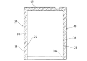
図1および図2に示す如く、実施例に係る貯蔵庫32(図3参照)の本体は、外箱10、内箱24および両箱10,24の間に画成される空間26に充填した発泡ウレタン等の断熱材28からなる断熱箱体30として構成され、該箱体30には前方に開放する矩形状の開口部30aが設けられている。断熱箱体30には、その幅方向の一側(実施例では右側)の上下に一対のヒンジ部材34(上方のみ図4に図示)が配設され、両ヒンジ部材34に回動可能に枢支した開閉扉36により、前記開口部30aを開閉するよう構成される。
【0011】
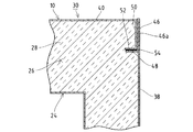
前記外箱10は、一対の側面板(板材)38,38、背面板(別の板材)40、天面板42および底面板44を相互に組付けることにより、前方に開放する箱状に構成される。この外箱10を構成する各側面板38の後端部(端部)には、図1に示す如く、その端部(端縁部)を内側(空間26側)に折返した折返し部46aが側面板38の内面に所定長さに亘って当接状態で重なるハゼ折り部46が形成されると共に、内側に臨む前記折返し部46aの端部を、側面板38から離間する内側に向けて略直角に折曲げることで所定長さの支持部48が形成されている。
【0012】
前記外箱10を構成する背面板40の幅方向両端部には、図1に示す如く、内側に向けて略直角に折曲げられた折曲部50が形成されると共に、該折曲部50の端部に、該端部をハゼ折り部46から離間する方向に略直角に折曲げることで所定長さの支持部52が形成されている。そしてこの背面板40は、前記側面板38のハゼ折り部46における折返し部46aに対し折曲部50が内側で平行に対向すると共に、側面板38の支持部48に対して支持部52が後側で平行に対向する状態で、側面板38に対して組付けられるよう構成される。また両支持部48,52の間にシール材54が介挿され、後述する断熱材28の空間26への充填発泡に際して発泡洩れが発生するのを防止するよう構成されている。なお、背面板40における折曲部50の長さ寸法は、前記側面板38におけるハゼ折り部46の長さ寸法より短かく設定され、両支持部48,52の間にシール材54を介挿した状態で、ハゼ折り部46の後端(折返し部46aが折返された端部)が所定長さだけ背面板40の後面より後方(外方)に延出するよう設定される。
【0013】
前記外箱10を構成する各側面板38の上端縁および前端縁には、他方の側面板38に向けて略直角に折曲げられた第1上フランジ38aおよび前フランジ38bが形成されると共に、該前フランジ38bの上端縁に背面板40に向けて略直角に折曲げられた第2上フランジ38cが形成されている。また両側面板38,38の間には、図4に示す如く、その上端部間に前面板56が架設されており、該前面板56の上端縁には、側面板38の第2上フランジ38cと平行なフランジ56aが同一レベルで折曲形成されている。そして、前記天面板42は、左右の側面板38,38の各第1および第2上フランジ38a,38cおよび前面板56のフランジ56a上に載置された状態で組付けられるようになっている。なお、図示しないが、背面板40の上端縁にも、天面板42が載置されるフランジが形成される。
【0014】
前記外箱10の正面右側の内側には、前記ヒンジ部材34をネジ止め固定するためのネジ板58が配設されている。このネジ板58は、図5および図6に示す如く、前記天面板42の内面(下面)に当接可能な水平部58aと、該水平部58aの前端部において下方に略直角に折曲げられて垂下する垂直部58bとから構成される。そしてネジ板58は、水平部58aを天面板42の内面に当接し、垂直部58bを側面板38における前フランジ38bの内面に当接し、更に水平部58aの側面板38と対向する側端部を該側面板38の内面に当接することで、外箱10に対して位置決めされるようになっている。またネジ板58は、側面板38の第1上フランジ38aおよび天面板42にリベット60を介して固定され、該ネジ板58を固定するためのリベットやネジ等の固定部材が、外箱10の前面側に露出しないよう構成される。
【0015】
前記ネジ板58の水平部58aには、複数(実施例では4つ)のネジ孔58cが形成されると共に、前記天面板42の対応位置に通孔42aが夫々形成されている。また前記ヒンジ部材34は、図5に示す如く、前記開閉扉36を回動可能に支持するヒンジピン62と、該ピン62が配設される支持板64とから構成され、該支持板64には、ネジ板58の各ネジ孔58cと対応する位置に通孔64aが夫々形成される。そして図5に示す如く、ヒンジ部材34の支持板64を天面板42の外面(上面)に当接載置した状態で、各通孔64a,42aを介して上方から挿通したネジ66を対応のネジ孔58cに螺挿することで、該ヒンジ部材34は外箱10(断熱箱体30)に位置決め固定されるよう構成してある。
【0016】
前記ネジ板58の水平部58aには、図6に示す如く、側面板38の前フランジ38bの上縁端に形成されている第2上フランジ38cを介して天面板42の内面に当接する位置に空気抜き孔58dが形成されている。また、ネジ板58の空気抜き孔58dと対応する位置の第2上フランジ38cおよび天面板42に空気抜き孔38d,42bが形成されており、外箱10と内箱24とで画成される前記空間26に断熱材28を充填発泡する際に、該ネジ板58の取付け部において確実に空気抜きを行なって、断熱材28の円滑かつ均一な充填発泡を確保し得るよう構成されている。
【0017】
なお、前記外箱10の正面左側の内側にも、前述したネジ板58と対称構造のネジ板58が、同一の構造によって配設固定されており、前記ヒンジ部材34をネジ止め固定するネジ板58を変更することで、前記開閉扉36の開放向きを選択し得るよう構成されている。また左側のネジ板58の取付け部においても、空気抜き孔が形成されて、断熱材28の充填発泡の際の空気抜きを確実に行ない得るようになっていることは同様である。
【0018】
【実施例の作用】
次に、実施例に係る断熱箱体の組付け構造の作用につき、以下説明する。前記外箱10の組立てに際し、前記各側面板38と背面板40とでは、図1に示す如く、側面板38のハゼ折り部46(折返し部46a)の内側に、背面板40の折曲部50を平行に対向するよう臨ませると共に、側面板38の支持部48と背面板40の支持部52とを前後に対向して組付ける。また両支持部48,52の間に、シール材54を介挿する。この場合に、シール材54は、予め何れか一方の支持部48,52の対向面側に貼付けておけばよい。なお、側面板38のハゼ折り部46と背面板40の折曲部50とは、必要最小限の隙間を存して対向すると共に、ハゼ折り部46の後端は、所定長さだけ背面板40の後面から後方に延出している。
【0019】
前記前面板56に左右の側面板38,38を組付けた後、両側面板38,38に前述したようにして背面板40を組付けると共に底面板44を組付け、最後に天面板42を組付ける。また前記左右の各ネジ板58を、その水平部58aを天面板42の内面に当接し、垂直部58bを側面板38における前フランジ38bの内面に当接し、更に水平部58aの側端部を側面板38の内面に当接することで、外箱10に対して位置決めした後、リベット60を介して天面板42に固定する。この場合に、ネジ板58を固定するためのリベットやネジ等の固定部材は、外箱10の前面側にはないので、外観上の見栄えが劣ることはない。また、ネジ板58と外箱10とを1本のリベット60で固定したので、組立て工数やコストを低廉に抑えることができる。
【0020】
前述したように構成した外箱10の内部に所要の空間26を存して内箱24を収納した状態で、該空間26に断熱材28を充填発泡させることで、断熱箱体30が構成される。この場合に、前記側面板38と背面板40との組付け部では、断熱材28を充填発泡する前の状態で、背面板40の後面より側面板38のハゼ折り部46の後端を所定長さだけ後方に延出してあるから、断熱材28の発泡時または2次発泡による発泡圧により背面板40が後方に膨らんだとしても、該背面板40がハゼ折り部46より後方に膨出することはなく、断熱箱体30を側方から見た外観上の良好な見栄えを保ち得る。なお、背面板40における折曲部50の角部は、側面板38のハゼ折り部46より前側に引込んでいるので、各種作業に際して外箱10を安全に取扱い得る。
【0021】
また前記シール材54は、図1に示す如く、空間26内において前後に対向する側面板38の支持部48と背面板40の支持部52との間に介挿してあるから、該シール材54は断熱箱体30の後側から見えることはなく、外観上の見栄えは良好となる。しかも、前記ハゼ折り部46と折曲部50との間にシール材を介挿するものではないので、両者46,50の隙間を必要最小限に設定することができ、該隙間が外観上の見栄えを損ねることはない。更に、側面板38と背面板40との組付け部において、側面板38の後端部を板片を当接状態で重ねたハゼ折り形状としてあるから、断熱材28の充填発泡時にハゼ折り部46に発泡液が入り込むことはなく、側面板38に歪みが生じたり発泡洩れが発生するのを好適に防止し得る。すなわち、側面板38の歪みや発泡洩れに起因して断熱箱体30の寸法精度が低下することはなく、完成後の断熱箱体30の全体の見栄えも良好となる。
【0022】
なお、前記断熱材28の空間26への充填発泡は、断熱材28を充填する前の断熱箱体30の開口部30aを上向きとした姿勢で、外箱10の底面側から行なわれる。すなわち、前記外箱10の天井前側に配設される各ネジ板58の取付け部は、断熱材28の充填側から離間する最上位置となる。この場合に、前記外箱10に対するネジ板58の取付け部では、該ネジ板58に空気抜き孔58dが形成されているから、内部空気の確実な空気抜きがなされ、発泡液の回りが良くなって発泡密度を均一とし得る。従って、完成後の断熱箱体30の断熱性能が向上すると共に、該断熱箱体30の寸法精度も向上して、外観上の見栄えが良好となる。
【0024】
【発明の効果】
以上に述べた如く、本発明に係る断熱箱体の組付け構造によれば、外箱と内箱との間の空間内において、断熱箱体の外側から見えない位置で対向する側面板の支持部と背面板の支持部との間にシール材を介挿したので、外観上の見栄えを良好とし得る。また、断熱箱体の外面に露出するハゼ折り部と折曲部との間にシール材を介挿するものではないので、両者の隙間を必要最小限に設定することができ、該隙間が外観上の見栄えを損ねることはない。更に、側面板と背面板との組付け部において、断熱材の充填発泡時にハゼ折り部に発泡液が入り込むことはなく、ハゼ折り部が形成される側面板に歪みが生じたり発泡洩れが発生するのを好適に防止し得る。すなわち、側面板および背面板の歪みや発泡洩れに起因して断熱箱体の寸法精度が低下することはなく、完成後の断熱箱体の全体の見栄えを良好とし得る。
【0025】
前記外箱を構成する側面板および背面板の組付け部において、断熱材を充填発泡する前の状態で、側面板に形成されたハゼ折り部の端部を背面板より所定長さだけ外方に延出するよう設定したので、断熱材の発泡時または2次発泡による発泡圧により背面板が外方に膨らんだとしても、該背面板がハゼ折り部より外方に膨出することはなく、断熱箱体の外観上の良好な見栄えを保ち得る。
【図面の簡単な説明】
【図1】 本発明の実施例に係る組付け構造を採用した断熱箱体の要部横断平面図である。
【図2】 実施例に係る断熱箱体の横断平面図である。
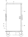
【図3】 実施例に係る断熱箱体を採用した貯蔵庫を示す側面図である。
【図4】 実施例に係る断熱箱体の要部正面図である。
【図5】 実施例に係る断熱箱体の要部縦断側面図である。
【図6】 実施例に係る断熱箱体の要部平面図である。
【図7】 従来の技術に係る断熱箱体の横断平面図である。
【符号の説明】
10 外箱,24 内箱,26 空間,28 断熱材,38 側面板(板材)
40 背面板(別の板材),46 ハゼ折り部,46a 折返し部,48 支持部
50 折曲部,52 支持部,54 シール材[0001]
BACKGROUND OF THE INVENTION
The present invention relates to an assembly structure of a heat insulating box, and more specifically, in a heat insulating box filled with a heat insulating material in a space between an outer box and an inner box, for example, a back plate and a side plate constituting the outer box It is related with the assembly | attachment structure of the heat insulation box which made it possible to improve the external appearance of this assembly part.
[0002]
[Prior art]
The main body of storage such as large commercial refrigerators and refrigerated showcases installed in stores is filled with heat insulating material in the space between the outer box as the outer casing and the inner box that defines the interior. It is comprised as a heat insulation box by interposing with a means. The outer box is constructed by assembling a pair of side plates, a back plate, a top plate and a bottom plate to each other. The structure disclosed in Japanese Patent No. 90654 is known. If this assembly structure is described with reference to FIG. 7, a
[0003]
And the
[0004]
[Problems to be solved by the invention]
In the assembly portion of the
[0005]
Further, since the sealing
[0006]
Further, the foamed liquid easily enters the
[0007]
OBJECT OF THE INVENTION
In view of the above-mentioned problems inherent in the prior art described above, the present invention has been proposed to suitably solve this problem, and the appearance of the assembling portion of each plate material constituting the outer box is visually appealing. It is an object of the present invention to provide a heat insulating box assembly structure that can improve foaming and prevent foam leakage and deterioration of dimensional accuracy.
[0008]
[Means for Solving the Problems]
In order to overcome the above-described problems and achieve the intended purpose suitably, the assembly structure of the heat insulation box according to the present invention is as follows.
In the heat insulation box composed of the outer box, the inner box provided through the required space inside the outer box, and the heat insulating material filled in the space between the two boxes,
The end portion of the side plates constituting the outer box, folding goby overlap folded portion folded ends of the side plates inwardly directed the space over a predetermined length on the inner surface of the side plate in a contact state A support portion is formed by bending the end portion of the folded portion in a direction away from the side plate .
In addition, a bent portion that is bent inward so as to be parallel to the folded portion of the goby folded portion is formed at an end portion of the back plate constituting the outer box, and an end portion of the bent portion Is formed in a direction away from the goby fold, forming a support part,
With bent portions are opposed to exist a gap minimum back plate (40) with respect to the folded portion of the side plate, facing the support portion of the back plate relative to the support portions of the side plates, two support portions The space is filled with a heat insulating material in a state where a sealing material is interposed between the two.
[0009]
DETAILED DESCRIPTION OF THE INVENTION
Next, the assembly structure of the heat insulating box according to the present invention will be described with reference to the accompanying drawings by giving a preferred embodiment. In addition, the same code | symbol shall be attached | subjected and shown to the same member which has already appeared in the prior art demonstrated with reference to FIG.
[0010]
As shown in FIGS. 1 and 2, the main body of the storage 32 (see FIG. 3) according to the embodiment is a foam filled in a
[0011]
The
[0012]
At both ends in the width direction of the
[0013]
A first
[0014]
A
[0015]
A plurality (four in the embodiment) of
[0016]
The
[0017]
A
[0018]
[Effect of the embodiment]
Next, the operation of the heat insulating box assembly structure according to the embodiment will be described below. When the
[0019]
After the left and
[0020]
The
[0021]
Further, as shown in FIG. 1, the
[0022]
The filling and foaming of the
[0024]
【The invention's effect】
As described above, according to the assembly structure of the heat insulation box according to the present invention, the side plates that are opposed to each other at a position that cannot be seen from the outside of the heat insulation box in the space between the outer box and the inner box are supported. Since the sealing material is interposed between the portion and the support portion of the back plate , the appearance can be improved. In addition, since the sealing material is not inserted between the goby folded part and the bent part exposed at the outer surface of the heat insulation box, the gap between the two can be set to the minimum necessary, and the gap is the appearance. There is no loss of the above appearance. Furthermore, at the assembly part of the side plate and the back plate , the foaming liquid does not enter the goby fold when filling and foaming the heat insulating material, and the side plate where the goby fold is formed is distorted or foam leakage occurs. This can be suitably prevented. That is, the dimensional accuracy of the heat insulation box does not decrease due to distortion of the side plate and the back plate or foam leakage, and the overall appearance of the heat insulation box after completion can be improved.
[0025]
In the assembled portion of the side plate and the back plate constituting the outer box, the end of the goby fold formed on the side plate is outward from the back plate by a predetermined length before filling and foaming the heat insulating material. since was set to extend, even as a back plate outwardly bulged by foaming pressure due to foaming during or secondary foam insulation, never the back plate bulges outward from portion folding goby The appearance of the heat insulation box can be kept good.
[Brief description of the drawings]
FIG. 1 is a cross-sectional plan view of an essential part of a heat insulating box that employs an assembly structure according to an embodiment of the present invention.
FIG. 2 is a cross-sectional plan view of a heat insulating box according to an embodiment.
FIG. 3 is a side view showing a storage that employs the heat insulating box according to the embodiment.
FIG. 4 is a front view of a main part of a heat insulation box according to an embodiment.
FIG. 5 is a longitudinal sectional side view of a main part of a heat insulating box according to an embodiment.
FIG. 6 is a plan view of a principal part of a heat insulating box according to an embodiment.
FIG. 7 is a cross-sectional plan view of a heat insulation box according to the prior art.
[Explanation of symbols]
10 outer box, 24 inner box, 26 space, 28 heat insulating material, 38 side plate (plate material)
40 Back plate (another plate material), 46 goby fold, 46a folded portion, 48 support portion 50 bent portion, 52 support portion, 54 sealing material
Claims (2)
前記外箱(10)を構成する側面板(38)の端部に、該側面板(38)の端部を前記空間(26)を指向する内側に折返した折返し部(46a)が側面板(38)の内面に所定長さに亘って当接状態で重なるハゼ折り部(46)が形成されると共に、前記折返し部(46a)の端部を側面板(38)から離間する方向に折曲げることで支持部(48)が形成され、
また前記外箱(10)を構成する背面板(40)の端部に、前記ハゼ折り部(46)の折返し部 (46a)と平行となるよう内側に向けて折曲げられた折曲部(50)が形成されると共に、該折曲部(50)の端部をハゼ折り部(46)から離間する方向に折曲げることで支持部(52)が形成され、
前記側面板(38)の折返し部(46a)に対し背面板 (40) の折曲部 (50) が必要最小限の隙間を存して対向すると共に、側面板 (38) の支持部 (48) に対し背面板 (40) の支持部(52)を対向し、両支持部(48,52)の間に亘ってシール材(54)が介挿された状態で、前記空間(26)に断熱材(28)が充填されている
ことを特徴とする断熱箱体の組付け構造。Fill the outer box (10), the inner box (24) provided inside the outer box (10) via the required space (26), and the space (26) between both boxes (10, 24) In the heat insulation box made of the heat insulation material (28),
The end portion of the side plate (38) constituting said outer box (10), folded portions of the end portions folded inwardly directed to said space (26) of said side plates (38) (46a) is a side plate ( A goby fold (46) is formed that overlaps the inner surface of 38) in a contact state over a predetermined length, and the end of the folded portion (46a) is bent away from the side plate (38). The support part (48) is formed,
Further, at the end portion of the back plate (40) constituting the outer box (10), a bent portion (inwardly folded ) so as to be parallel to the folded portion (46a) of the goby folded portion (46) ( 50) is formed, and the support portion (52) is formed by bending the end of the bent portion (50) in a direction away from the goby fold (46),
The bent portion (50) of the back plate (40) faces the folded portion (46a) of the side plate (38) with a necessary minimum gap, and the support portion (48 of the side plate (38)). ) faces the supporting unit (52) of the back plate (40) to, in a state where the sealing member (54) is interposed over between the two support portions (48, 52), said space (26) A heat insulating box assembly structure, characterized by being filled with a heat insulating material (28).
Priority Applications (1)
| Application Number | Priority Date | Filing Date | Title |
|---|---|---|---|
| JP29452899A JP3689286B2 (en) | 1999-10-15 | 1999-10-15 | Insulation box assembly structure |
Applications Claiming Priority (1)
| Application Number | Priority Date | Filing Date | Title |
|---|---|---|---|
| JP29452899A JP3689286B2 (en) | 1999-10-15 | 1999-10-15 | Insulation box assembly structure |
Publications (2)
| Publication Number | Publication Date |
|---|---|
| JP2001116440A JP2001116440A (en) | 2001-04-27 |
| JP3689286B2 true JP3689286B2 (en) | 2005-08-31 |
Family
ID=17808958
Family Applications (1)
| Application Number | Title | Priority Date | Filing Date |
|---|---|---|---|
| JP29452899A Expired - Fee Related JP3689286B2 (en) | 1999-10-15 | 1999-10-15 | Insulation box assembly structure |
Country Status (1)
| Country | Link |
|---|---|
| JP (1) | JP3689286B2 (en) |
Families Citing this family (2)
| Publication number | Priority date | Publication date | Assignee | Title |
|---|---|---|---|---|
| JP4242358B2 (en) | 2005-03-14 | 2009-03-25 | ホシザキ電機株式会社 | Insulated box and method for manufacturing the same |
| CN104019608A (en) * | 2013-02-28 | 2014-09-03 | 严斌 | Connecting piece of liner and shell of refrigerator and wine cabinet |
-
1999
- 1999-10-15 JP JP29452899A patent/JP3689286B2/en not_active Expired - Fee Related
Also Published As
| Publication number | Publication date |
|---|---|
| JP2001116440A (en) | 2001-04-27 |
Similar Documents
| Publication | Publication Date | Title |
|---|---|---|
| EP3008405B1 (en) | Refrigerator | |
| US11142223B2 (en) | Side wall component of railway vehicle, and railway vehicle | |
| CN100541083C (en) | Heat insulation box and its manufacturing method | |
| CN102119312B (en) | Door for a household appliance | |
| JP6544377B2 (en) | Speaker arrangement structure of vehicle | |
| JP2021113678A (en) | refrigerator | |
| JP2001116440A (en) | Fixing structure of heat insulating box | |
| JP2000318446A (en) | Rear door of vehicle | |
| JP4006901B2 (en) | refrigerator | |
| JP4225441B2 (en) | Automatic ice machine door structure | |
| JP2581795Y2 (en) | Paper box with partition | |
| TWI911679B (en) | Refrigerator | |
| JP3591388B2 (en) | Outdoor unit of air conditioner | |
| JP3689253B2 (en) | Assembly structure of heat insulation box | |
| JP7851135B2 (en) | Refrigerator door and refrigerator | |
| JPH018938Y2 (en) | ||
| JP2003214761A (en) | Assembling structure of heat insulation box | |
| JPH04155172A (en) | Storage cabinet | |
| JP7484647B2 (en) | Packaging box | |
| CN110345683A (en) | Door and refrigerator for refrigerator | |
| KR100354398B1 (en) | Microwave oven | |
| JPH09286463A (en) | Shock-absorbing material for packing | |
| JP3364561B2 (en) | Refrigerator door | |
| JPS5913588Y2 (en) | box body | |
| JP2013083373A (en) | Refrigerator |
Legal Events
| Date | Code | Title | Description |
|---|---|---|---|
| A977 | Report on retrieval |
Free format text: JAPANESE INTERMEDIATE CODE: A971007 Effective date: 20050304 |
|
| A131 | Notification of reasons for refusal |
Free format text: JAPANESE INTERMEDIATE CODE: A131 Effective date: 20050315 |
|
| A521 | Written amendment |
Free format text: JAPANESE INTERMEDIATE CODE: A523 Effective date: 20050513 |
|
| TRDD | Decision of grant or rejection written | ||
| A01 | Written decision to grant a patent or to grant a registration (utility model) |
Free format text: JAPANESE INTERMEDIATE CODE: A01 Effective date: 20050531 |
|
| A61 | First payment of annual fees (during grant procedure) |
Free format text: JAPANESE INTERMEDIATE CODE: A61 Effective date: 20050610 |
|
| R150 | Certificate of patent or registration of utility model |
Free format text: JAPANESE INTERMEDIATE CODE: R150 |
|
| FPAY | Renewal fee payment (event date is renewal date of database) |
Free format text: PAYMENT UNTIL: 20090617 Year of fee payment: 4 |
|
| FPAY | Renewal fee payment (event date is renewal date of database) |
Free format text: PAYMENT UNTIL: 20090617 Year of fee payment: 4 |
|
| FPAY | Renewal fee payment (event date is renewal date of database) |
Free format text: PAYMENT UNTIL: 20100617 Year of fee payment: 5 |
|
| FPAY | Renewal fee payment (event date is renewal date of database) |
Free format text: PAYMENT UNTIL: 20110617 Year of fee payment: 6 |
|
| LAPS | Cancellation because of no payment of annual fees |